Z17785.18 8.06.02-241/15 European Technical Assessment ETA-11/0311 of 20 April 2018 English translation prepared by DIBt - Original version in German language General Part Technical Assessment Body issuing the European Technical Assessment: Deutsches Institut für Bautechnik Trade name of the construction product HALFEN Tension Rod System DETAN-E Product family to which the construction product belongs Prefabricated Tension Rod System Manufacturer HALFEN GmbH Liebigstraße 14 40764 Langenfeld DEUTSCHLAND Manufacturing plant HALFEN GmbH Otto-Brünner-Straße 3 06556 Artern DEUTSCHLAND This European Technical Assessment contains 18 pages including 13 annexes which form an integral part of this assessment This European Technical Assessment is issued in accordance with Regulation (EU) No 305/2011, on the basis of EAD 200032-00-0602 This version replaces ETA-11/0311 issued on 19 April 2013 electronic copy of the eta by dibt: eta-11/0311
Transcript
Z17785.18 8.06.02-241/15
European Technical
Assessment
ETA-11/0311
of 20 April 2018 English translation prepared by DIBt - Original version in German language General Part
Technical Assessment Body issuing the European Technical Assessment:
Deutsches Institut für Bautechnik
Trade name of the construction product HALFEN Tension Rod System DETAN-E
Product family to which the construction product belongs
Prefabricated Tension Rod System
Manufacturer HALFEN GmbH Liebigstraße 14 40764 Langenfeld DEUTSCHLAND
Manufacturing plant HALFEN GmbH Otto-Brünner-Straße 3 06556 Artern DEUTSCHLAND
This European Technical Assessment contains
18 pages including 13 annexes which form an integral part of this assessment
This European Technical Assessment is issued in accordance with Regulation (EU) No 305/2011, on the basis of
EAD 200032-00-0602
This version replaces ETA-11/0311 issued on 19 April 2013
elec
troni
c co
py o
f the
eta
by
dibt
: et
a-11
/031
1
European Technical Assessment
ETA-11/0311
English translation prepared by DIBt
Page 2 of 18 | 20 April 2018
Z17785.18 8.06.02-241/15
The European Technical Assessment is issued by the Technical Assessment Body in its official language. Translations of this European Technical Assessment in other languages shall fully correspond to the original issued document and shall be identified as such.
Communication of this European Technical Assessment, including transmission by electronic means, shall be in full. However, partial reproduction may only be made with the written consent of the issuing Technical Assessment Body. Any partial reproduction shall be identified as such.
This European Technical Assessment may be withdrawn by the issuing Technical Assessment Body, in particular pursuant to information by the Commission in accordance with Article 25(3) of Regulation (EU) No 305/2011.
elec
troni
c co
py o
f the
eta
by
dibt
: et
a-11
/031
1
European Technical Assessment
ETA-11/0311
English translation prepared by DIBt
Page 3 of 18 | 20 April 2018
Z17785.18 8.06.02-241/15
Specific part
1 Technical description of the product
The construction product is a prefabricated tension rod system of different system sizes used as a kit. The tension rod system consists of stainless steel bars (tension rods) with external threads which are connected to each other and to the corresponding structure by special connecting devices. The tension rods are connected to the corresponding structure by stainless steel cast or drop-forged fork end connectors with two eye loops and internal thread. The fork end connectors are connected by double shear pin connections to corresponding gusset plates or anchor discs. The tension rods are connected to each other by stainless threaded steel sleeves (couplers, couplers with additional gusset plate, hexagon couplers and cross couplers).
The tension rod system comprises tension rods, fork end connectors, gusset plate, anchor discs, pins and threaded sleeves with metric ISO threads M 6 to M 48.
Drawings of the tension rod system and the components as well as the essential dimensions of the components are given in the Annexes to this ETA.
The dimensions, tolerances and materials of the components of the tension rod system not indicated in Annexes shall correspond to the respective values and information laid down in the technical documentation1 to this European Technical Assessment.
2 Specification of the intended use in accordance with the applicable European Assessment Document
The tension rod system is intended for the use in structures with static or quasi-static loads in accordance with EN 1990:2002, where no verification of fatigue relating to EN 1993-1-9:2005 is necessary.
The intended use comprises for instance the suspension of roof structures or vertical glazing as well as bracing and truss structures.
The tension rod system is not subjected to systematic bending.
The fork end connectors may also be connected to compression rods. The compression rods themselves are not part of the ETA.
The performances given in Section 3 are only valid if the tension rod system is used in compliance with the specifications and conditions given in Annex A and Annexes B1 to B9.
The verifications and assessment methods on which this European Technical Assessment is based lead to the assumption of a working life of the tension rod system of at least 25 years. The indications given on the working life cannot be interpreted as a guarantee given by the producer, but are to be regarded only as a means for choosing the right products in relation to the expected economically reasonable working life of the works.
1 The technical documentation to this European Technical Assessment is deposited with Deutsches Institut für
Bautechnik and, as far as relevant for the tasks of the approved bodies involved in the attestation of conformity procedure is handed over to the approved bodies.
elec
troni
c co
py o
f the
eta
by
dibt
: et
a-11
/031
1
European Technical Assessment
ETA-11/0311
English translation prepared by DIBt
Page 4 of 18 | 20 April 2018
Z17785.18 8.06.02-241/15
3 Performance of the product and references to the methods used for its assessment
Reaction to fire Class A1 in accordance with EN 13501-1:2007+A1:2009
The components of the tension rod system satisfy the requirements for performance class A1 of the characteristic reaction to fire, in accordance with the provisions of EC decision 96/603/EC (as amended).
3.3 Safety and accessibility in use (BWR 4)
Same as BWR 1.
elec
troni
c co
py o
f the
eta
by
dibt
: et
a-11
/031
1
European Technical Assessment
ETA-11/0311
English translation prepared by DIBt
Page 5 of 18 | 20 April 2018
Z17785.18 8.06.02-241/15
4 Assessment and verification of constancy of performance (AVCP) system applied, with reference to its legal base
In accordance with European Assessment Document EAD No. 200032-00-0602, the applicable European legal act is: 98/214/EC.
The system to be applied is: 2+
5 Technical details necessary for the implementation of the AVCP system, as provided for in the applicable EAD
Technical details necessary for the implementation of the AVCP system are laid down in the control plan deposited with Deutsches Institut für Bautechnik.
Issued in Berlin on 20 April 2018 by Deutsches Institut für Bautechnik
BD Dipl.-Ing. Andreas Kummerow beglaubigt:
Head of Department Bertram
elec
troni
c co
py o
f the
eta
by
dibt
: et
a-11
/031
1
Page 6 of European Technical Assessment
ETA-11/0311 of 20 April 2018
Z26745.18 8.06.02-241/15
Annex A
A.1 Assumptions concerning design
The design of the tension rod system is carried out under the following conditions:
The loading is static or quasi-static in accordance with EN 1990:2002 without need of verification of fatigue relating to EN 1993-1-9:2005.
The tension rod systems are not used, when constructions are susceptible to vibrations under wind loads or wind-induced cross vibrations of the entire construction appear.1
Dimensions, material properties and screw-in lengths given in Annex B are observed.
The tension rod system is not subjected to systematic bending.
The verification concept stated in EN 1990:2002 as well as the design values of resistance stated below are used for design.
The rules given in EN 1090-2:2008, EN ISO 12944:1998 and EN 1993-1-4:2006 are taken into account.
Design is carried out by the designer of the structure experienced in the field of steel structures.
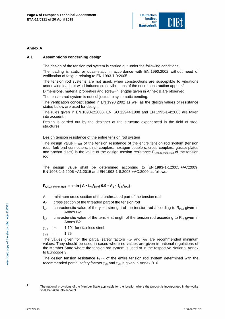
Design tension resistance of the entire tension rod system
The design value Ft,RD of the tension resistance of the entire tension rod system (tension rods, fork end connectors, pins, couplers, hexagon couplers, cross couplers, gusset plates and anchor discs) is the value of the design tension resistance Ft,Rd,Tension Rod of the tension rod.
The design value shall be determined according to EN 1993-1-1:2005 +AC:2009, EN 1993-1-4:2006 +A1:2015 and EN 1993-1-8:2005 +AC:2009 as follows:
Ft,RD,Tension Rod = min A fy,k/M0; 0.9 AS fu,k/M2
A minimum cross section of the unthreaded part of the tension rod
AS cross section of the threaded part of the tension rod
fy,k characteristic value of the yield strength of the tension rod according to Rp0,2 given in Annex B2
fu,k characteristic value of the tensile strength of the tension rod according to Rm given in Annex B2
M0 = 1.10 for stainless steel
M2 = 1.25
The values given for the partial safety factors M0 and M2 are recommended minimum values. They should be used in cases where no values are given in national regulations of the Member State where the tension rod system is used or in the respective National Annex to Eurocode 3.
The design tension resistance Ft,RD of the entire tension rod system determined with the
recommended partial safety factors M0 and M2 is given in Annex B10.
1 The national provisions of the Member State applicable for the location where the product is incorporated in the works
shall be taken into account.
elec
troni
c co
py o
f the
eta
by
dibt
: et
a-11
/031
1
Page 7 of European Technical Assessment
ETA-11/0311 of 20 April 2018
Z26745.18 8.06.02-241/15
Design values of the compression force of tension rods and compression rods
The design value of the compression force Fc,RD of tension rods or compression rods in combination with fork end connectors in accordance with Annex B3 is the minimum value of
the design value of the compression force of struts in the cross-section of the thread and
the design value of the compression force of struts calculated in accordance with EN 1993-1-1:2005 and EN 1993-1-4:2006.
The design value of the compression force of struts in the cross-section of the thread Fc,RD
should be determined as follows:
𝐹𝑐,𝑅𝐷 = [𝛾𝑀2
𝐴𝑆 ∙ 𝑓𝑢,𝑐
+ (
𝑤 − 𝑏2
+ 𝑛𝑅𝑉50
) ∙ 𝛾𝑀0
𝑊𝑝𝑙,𝑠 ∙ 𝑓𝑦,𝑐
]
−1
AS tensile stress area of the thread
Wpl,S
plastic section modulus of the core cross section
fy,c
characteristic value of the yield strength of the strut, where fy,c = ReH
characteristic value of the yield strength of the strut in accordance with product standard
fu,c
characteristic value of the tension resistance of the strut, where fu,c = Rm
characteristic value of the tensile strength of the strut in accordance with product standard
The dimensions of w, b, nRV are stated in Annex B3.
Recommended values for the partial safety factors M0 and M2 are:
M0 = 1.10 for stainless steel
M2 = 1.25
The design value of the compression force of struts has to be determined in accordance with EN 1993-1-1:2005 and EN 1993-1-4:2006 considering the additional bending strength in consequence of one-sided contact of the gusset plates.
In addition EN 1993-1-1:2005 and EN 1993-1-4:2006 applies for verification against buckling.
elec
troni
c co
py o
f the
eta
by
dibt
: et
a-11
/031
1
Page 8 of European Technical Assessment
ETA-11/0311 of 20 April 2018
Z26745.18 8.06.02-241/15
A.2 Assumptions concerning Installation
The installation of the tension rod system is carried out under the following conditions:
The installation is only carried out in accordance with the manufacturer's instructions. The manufacturer hands over the assembly instructions to the assembler. From the assembly instructions it is followed that, prior to installation, all components of the tension rod system shall be checked for their perfect condition and that damaged components shall not be used.
The fork end connectors are not subjected to sudden or impact loads (for instance pins shall not be adjusted by hammer blows).
The minimum screw-in lengths are marked in an appropriate way. The compliance of the minimum screw-in lengths, given in Annex B, is checked by the assembler in accordance with the assembly instructions. The compliance of the screw-in lengths shall be attested with a written confirmation by a person responsible for the construction site.
The pins of the tension rod system are secured in their position with circlips.
The conformity of the installed tension rod system with the provisions of the ETA is attested by the executing assembler.
A.3 Indications to the manufacturer
The manufacturer shall ensure that the information on the specific conditions is given to those who are concerned. This information may be given by reproduction of the European Technical Assessment. In addition all essential installation data (e.g. minimum screw-in length in accordance with Annex B) shall be shown clearly on the package and/or on an enclosed instruction sheet, preferably using illustration(s).
The prefabricated tension rod system shall be packaged and delivered as a complete unit only (tension rods, fork end connectors incl. pins, threaded sleeves).
Longer systems may be separated at the couplers for easier transportation.
elec
troni
c co
py o
f the
eta
by
dibt
: et
a-11
/031
1
Page 9 of European Technical Assessment ETA-11/0311 of 20 April 2018
English translation prepared by DIBt
Z18958.18 8.06.02-241/15
HALFEN Tension Rod System DETAN-E
Anlagenbeschreibung
Annex X
HALFEN Tension Rod System DETAN-E
Components
Annex B1
elec
troni
c co
py o
f the
eta
by
dibt
: et
a-11
/031
1
Page 10 of European Technical Assessment ETA-11/0311 of 20 April 2018
English translation prepared by DIBt
Z18958.18 8.06.02-241/15
HALFEN Tension Rod System DETAN-E
Material properties of the components
Annex B2
elec
troni
c co
py o
f the
eta
by
dibt
: et
a-11
/031
1
Page 11 of European Technical Assessment ETA-11/0311 of 20 April 2018
English translation prepared by DIBt
Z18958.18 8.06.02-241/15
HALFEN Tension Rod System DETAN-E
Dimensions of the fork end connectors and minimum dimensions of the gusset plates
Annex B3
elec
troni
c co
py o
f the
eta
by
dibt
: et
a-11
/031
1
Page 12 of European Technical Assessment ETA-11/0311 of 20 April 2018
English translation prepared by DIBt
Z18958.18 8.06.02-241/15
HALFEN Tension Rod System DETAN-E
Dimensions of the tensions rods
Annex B4
elec
troni
c co
py o
f the
eta
by
dibt
: et
a-11
/031
1
Page 13 of European Technical Assessment ETA-11/0311 of 20 April 2018
English translation prepared by DIBt
Z18958.18 8.06.02-241/15
HALFEN Tension Rod System DETAN-E
Dimensions of the couplers
Annex B5
elec
troni
c co
py o
f the
eta
by
dibt
: et
a-11
/031
1
Page 14 of European Technical Assessment ETA-11/0311 of 20 April 2018
English translation prepared by DIBt
Z18958.18 8.06.02-241/15
HALFEN Tension Rod System DETAN-E
Dimensions of the couplers with additional gusset plate
Annex B6
elec
troni
c co
py o
f the
eta
by
dibt
: et
a-11
/031
1
Page 15 of European Technical Assessment ETA-11/0311 of 20 April 2018
English translation prepared by DIBt
Z18958.18 8.06.02-241/15
HALFEN Tension Rod System DETAN-E
Dimensions of the hexagon couplers
Annex B7
elec
troni
c co
py o
f the
eta
by
dibt
: et
a-11
/031
1
Page 16 of European Technical Assessment ETA-11/0311 of 20 April 2018
English translation prepared by DIBt
Z18958.18 8.06.02-241/15
HALFEN Tension Rod System DETAN-E
Dimensions of the cross couplers
Annex B8
elec
troni
c co
py o
f the
eta
by
dibt
: et
a-11
/031
1
Page 17 of European Technical Assessment ETA-11/0311 of 20 April 2018
English translation prepared by DIBt
Z18958.18 8.06.02-241/15
HALFEN Tension Rod System DETAN-E
Dimensions of the ancor discs K40, K60, K80
Annex B9
elec
troni
c co
py o
f the
eta
by
dibt
: et
a-11
/031
1
Page 18 of European Technical Assessment ETA-11/0311 of 20 April 2018
English translation prepared by DIBt
Z18958.18 8.06.02-241/15
HALFEN Tension Rod System DETAN-E
design tension resistance of the entire tension rod system