Centre Scientifique et Technique du Bâtiment 84 avenue Jean Jaurès CHAMPS-SUR-MARNE F-77447 Marne-la-Vallée Cedex 2 Tél. : (33) 01 64 68 82 82 Fax : (33) 01 60 05 70 37 Member of www.eota.eu European Technical Assessment ETA-14/0001 of 12/02/2014 English translation prepared by CSTB - Original version in French language General Part Nom commercial Trade name Hilti HIT-HY100 Famille de produit Product family Scellement d’armatures rapportées, diamètres 8 à 25mm, avec Système d’injection Hilti HIT-HY 100 Post installed rebar connections diameter 8 to 25 mm made with Hilti HIT-HY 100 injection mortar Titulaire Manufacturer Hilti Corporation Feldkircherstrasse 100 FL-9494 Schaan Principality of Liechtenstein Usine de fabrication Manufacturing plants Plant 6 Cette evaluation contient: This Assessment contains 17 pages incluant 14 annexes qui font partie intégrante de cette évaluation 17 pages including 14 annexes which form an integral part of this assessment Base de l‘ETE Basis of ETA ETAG 001 Partie 5, Version April 2013, utilisée en tant que EAD ETAG 001 Part 5, Edition April 2013 used as EAD Cette evaluation remplace: This Assessment replaces - Translations of this European Technical Assessment in other languages shall fully correspond to the original issued document and should be identified as such. Communication of this European Technical Assessment, including transmission by electronic means, shall be in full. However, partial reproduction may be made, with the written consent of the issuing Technical Assessment Body. Any partial reproduction has to be identified as such.
English translation prepared by CSTB - Original version in French language
General Part
Nom commercial Trade name
Hilti HIT-HY100
Famille de produit Product family
Scellement d’armatures rapportées, diamètres 8 à 25mm, avec Système d’injection Hilti HIT-HY 100
Post installed rebar connections diameter 8 to 25 mm made with Hilti HIT-HY 100 injection mortar
Titulaire Manufacturer
Hilti Corporation Feldkircherstrasse 100 FL-9494 Schaan Principality of Liechtenstein
Usine de fabrication Manufacturing plants
Plant 6
Cette evaluation contient: This Assessment contains
17 pages incluant 14 annexes qui font partie intégrante de cette évaluation 17 pages including 14 annexes which form an integral part of this assessment
Base de l‘ETE Basis of ETA
ETAG 001 Partie 5, Version April 2013, utilisée en tant que EAD
ETAG 001 Part 5, Edition April 2013 used as EAD
Cette evaluation remplace: This Assessment replaces
-
Translations of this European Technical Assessment in other languages shall fully correspond to the original issued document and should be identified as such. Communication of this European Technical Assessment, including transmission by electronic means, shall be in full. However, partial reproduction may be made, with the written consent of the issuing Technical Assessment Body. Any partial reproduction has to be identified as such.
European technical assessment ETA-14/0001
English translation prepared by CSTB
Page 2 of 17 | 12/02/2014
Specific part
1 Technical description of the product
The Hilti HIT-HY 100 is used for the connection, by anchoring or overlap joint, of reinforcing bars (rebars) in existing structures made of ordinary non-carbonated concrete C12/15 to C50/60. The design of the post-installed rebar connections is done in accordance with EN 1992-1-1 October 2005 (Eurocode 2).
Covered are rebar anchoring systems consisting of Hilti HIT-HY 100 bonding material and an embedded straight deformed reinforcing bar diameter, d, from 8 to 25 mm with properties according to Annex C of EN 1992-1-1 and EN 10080. The classes B and C of the rebar are recommended.
An illustration of the product is provided in Annex A.
2 Specification of the intended use
The performances given in Section 3 are only valid if the anchor is used in compliance with the specifications and conditions given in Annexes B.
The provisions made in this European Technical Assessment are based on an assumed working life of the anchor of 50 years. The indications given on the working life cannot be interpreted as a guarantee given by the producer, but are to be regarded only as a means for choosing the right products in relation to the expected economically reasonable working life of the works.
3 Performance of the product
3.1 Mechanical resistance and stability (BWR 1)
Essential characteristic Performance
Ultimate bond resistance fbd See Annex C 1
3.2 Safety in case of fire (BWR 2)
Essential characteristic Performance
Reaction to fire Anchorages satisfy requirements for Class A1
Resistance to fire No performance determined (NPD)
3.3 Hygiene, health and the environment (BWR 3)
Regarding dangerous substances contained in this European Technical Assessment, there may be requirements applicable to the products falling within its scope (e.g. transposed European legislation and national laws, regulations and administrative provisions). In order to meet the provisions of the Construction Products Directive, these requirements need also to be complied with, when and where they apply.
3.4 Safety in use (BWR 4)
For Basic requirement Safety in use the same criteria are valid as for Basic Requirement Mechanical resistance and stability.
3.5 Protection against noise (BWR 5)
Not relevant.
3.6 Energy economy and heat retention (BWR 6)
Not relevant.
3.7 Sustainable use of natural resources ( BWR 7)
For the sustainable use of natural resources no performance was determined for this product.
3.8 General aspects relating to fitness for use
Durability and Serviceability are only ensured if the specifications of intended use according to Annex B 1 are kept.
European technical assessment ETA-14/0001
English translation prepared by CSTB
Page 4 of 17 | 12/02/2014
Injection system Hilti HIT-HY 100 for rebar connection
Product description
Installed condition and examples of use for rebars
Annex A1
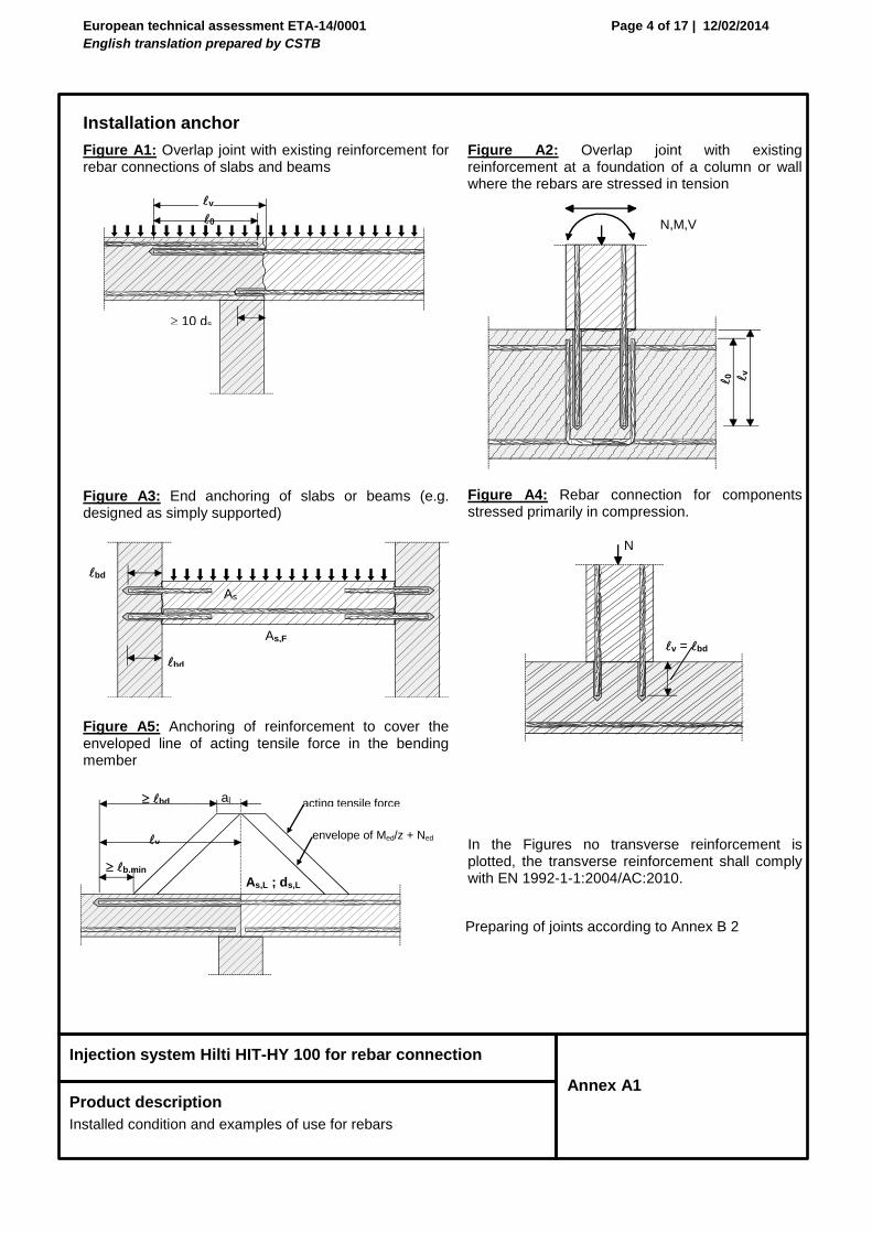
Installation anchor
Figure A1: Overlap joint with existing reinforcement for rebar connections of slabs and beams
Figure A3: End anchoring of slabs or beams (e.g. designed as simply supported)
Figure A5: Anchoring of reinforcement to cover the enveloped line of acting tensile force in the bending member
Figure A2: Overlap joint with existing reinforcement at a foundation of a column or wall where the rebars are stressed in tension
Figure A4: Rebar connection for components stressed primarily in compression.
Note to Figure A1 to A5:
In the Figures no transverse reinforcement is plotted, the transverse reinforcement shall comply with EN 1992-1-1:2004/AC:2010.
Preparing of joints according to Annex B 2
v = bd
N
acting tensile force bd
b,min As,L ; ds,L
v
al
envelope of Med/z + Ned
N,M,V
0
v
bd
bd
As
As,F
0
v
10 ds
European technical assessment ETA-14/0001
English translation prepared by CSTB
Page 5 of 17 | 12/02/2014
Injection system Hilti HIT-HY 100 for rebar connection
Product descripion
Injection mortar / Static mixer / Rebar
Annex A2
Injection mortar Hilti HIT-HY 100: hybrid system with aggregate
Minimum value of related rip area fR,min according to EN 1992-1-1:2004/AC:2010 The maximum outer rebar diameter over the rips shall be:
Nominal diameter of the bar d + 2 x h (h ≤ 0,07 x d) (d: Nominal diameter of the bar; h: Rip height of the bar)
Table A1 Materials
Part Designation Rebar
1 Rebar EN 1992-1-1:2004/AC:2010, Annex C
Bars and de-coiled rods Class B or C with fyk acc. EN 1992-1-1/NA:2013 fuk = ftk = kfyk
Marking
HILTI HIT
Production date
Production time and line
Expiry date mm/yyyy
Product name: “Hilti HIT-HY 100”
European technical assessment ETA-14/0001
English translation prepared by CSTB
Page 6 of 17 | 12/02/2014
Injection system Hilti HIT-HY 100 for rebar connection
Intended Use
Specifications
Annex B1
Specifications of intended use
Anchorages subject to:
Static and quasi-static loads.
Base materials:
Reinforced or unreinforced normal weight concrete according to EN 206-1:2000-12. Strength classes C12/15 to C50/60 according to EN 206-1:2000-12. Maximum chloride concrete of 0,40% (CL 0.40) related to the cement content according to
EN 206-1:2000-12. Non-carbonated concrete.
Note: In case of a carbonated surface of the existing concrete structure the carbonated layer shall be removed in the area of the post-installed rebar connection with a diameter of ds + 60 mm prior to the installation of the new rebar.
The depth of concrete to be removed shall correspond to at least the minimum concrete cover in accordance with EN 1992-1-1:2004 AC:2010.
The foregoing may be neglected if building components are new and not carbonated and if building components are in dry conditions.
Temperature Range:
- 40°C to +80°C (max. short term temperature +80°C and max long term temperature +50°C).
Design:
Anchorages are designed under the responsibility of an engineer experienced in anchorages and concrete work.
Verifiable calculation notes and drawings are prepared taking account of the forces to be transmitted. Design according to EN 1992-1-1:2004/AC:2010 and Annex B 2. The actual position of the reinforcement in the existing structure shall be determined on the basis of
the construction documentation and taken into account when designing.
Installation:
Dry or wet concrete. It must not be installed in flooded holes. Hole drilling by hammer drill or compressed air drill mode. The installation of post-installed rebar shall be done only by suitable trained installer and under
supervision on site; the conditions under which an installer may be considered as suitable trained and the conditions for supervision on site are up to the Member States in which the installation is done.
Check the position of the existing rebars (if the position of existing rebars is not known, it shall be determined using a rebar detector suitable for this purpose as well as on the basis of the construction documentation and then marked on the building component for the overlap joint).
.
European technical assessment ETA-14/0001
English translation prepared by CSTB
Page 7 of 17 | 12/02/2014
Injection system Hilti HIT-HY 100 for rebar connection
Intended Use
General construction rules for post-installed rebars
Annex B2
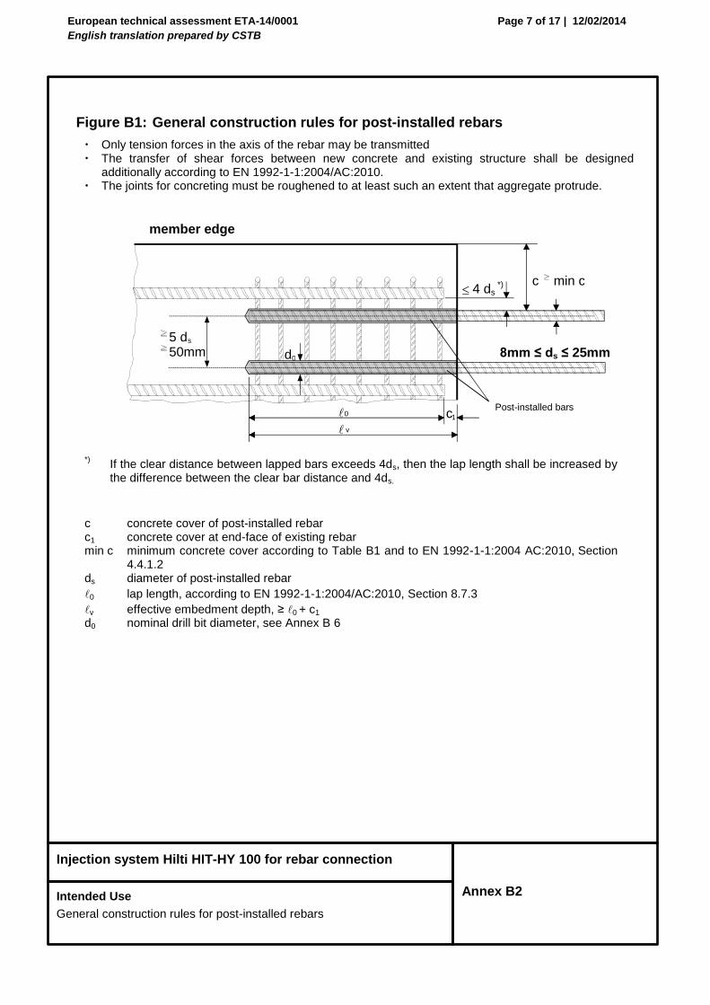
Figure B1: General construction rules for post-installed rebars
Only tension forces in the axis of the rebar may be transmitted The transfer of shear forces between new concrete and existing structure shall be designed
additionally according to EN 1992-1-1:2004/AC:2010. The joints for concreting must be roughened to at least such an extent that aggregate protrude.
*) If the clear distance between lapped bars exceeds 4ds, then the lap length shall be increased by
the difference between the clear bar distance and 4ds.
c concrete cover of post-installed rebar c1 concrete cover at end-face of existing rebar min c minimum concrete cover according to Table B1 and to EN 1992-1-1:2004 AC:2010, Section
4.4.1.2 ds diameter of post-installed rebar
0 lap length, according to EN 1992-1-1:2004/AC:2010, Section 8.7.3
v effective embedment depth, ≥ 0 + c1
d0 nominal drill bit diameter, see Annex B 6
Post-installed bars
c
min c
5 d s
d 0
50mm
0 c 1 v
4 ds *)
8mm ≤ ds ≤ 25mm
member edge
European technical assessment ETA-14/0001
English translation prepared by CSTB
Page 8 of 17 | 12/02/2014
Injection system Hilti HIT-HY 100 for rebar connection
Intended Use
Minimum concrete cover
Annex B3
Table B1: Minimum concrete cover min c 1) of the bonded-in rebar depending on drilling method and drilling tolerance
Drilling method Bar diameter ds Without drilling aid With drilling aid
Hammer drilling (HD)
< 25 mm
30mm + 0,06 v 2 ds 30mm + 0,02 v 2 ds
25 mm 40mm + 0,06 v 2 ds 40mm + 0,02 v 2 ds
Compressed air drilling (CA)
< 25 mm 50mm + 0,08 v 50mm + 0,02 v
25 mm 60mm + 0,08 v 60mm + 0,02 v 1)
see Annexes B2, Figures B1 Comments: The minimum concrete cover acc. EN 1992-1-1:2004/AC:2010 must be observed
Drilling aid
European technical assessment ETA-14/0001
English translation prepared by CSTB
Page 9 of 17 | 12/02/2014
Injection system Hilti HIT-HY 100 for rebar connection
Intended Use
Maximum embedment depth per dispenser/ working time and curing times
Annex B4
Table B2: Maximum permissible embedment depth lmax [mm] corresponding to
dispenser
Rebar Dispenser
Ø ds [mm]
HDM 330, HDM 500, HIT-MD 2000, HIT-MD 2500
HDE 500 HIT-ED 3500, HIT-P300F, HIT-P3500F
8
700
10
12
14
16
18
500
20
22
24
25
Remark: Injection of mortar at low temperatures is easier and faster when the mortar is heated up slowly to 20°C
Table B3: Working time twork and minimum curing time tcure
Temperature in the anchorage base [°C]
Maximum working time twork
Minimum curing time tcure
-10 to -6 180 min 12 h
-5 to -1 40 min 4 h
+0 to +4 20 min 2 h
+5 to +9 8 min 1 h
+10 to +14 7 min 50 min
+15 to +19 6 min 40 min
+20 to +24 5 min 30 min
+25 to +29 3 min 30 min
+30 to +40 2 min 30 min
European technical assessment ETA-14/0001
English translation prepared by CSTB
Page 10 of 17 | 12/02/2014
Injection system Hilti HIT-HY 100 for rebar connection
Intended Use
Installation tools for drilling with hammer drill (HD) or compressed air drill (CA)
Annex B5
Table B4: Installation tools for drilling with hammer drill (HD) or compressed air drill (CA)
Elements Drill and clean Installation
Rebar
-Ø
Hammer drilling (HD)
Compressed air drill (CA)
Steel brush Air Nozzle Extension for air nozzle
Piston plug
Extension for piston plug
Maximum embedment
depth
dnom
[mm]
d0
[mm]
d0
[mm] HIT-RB HIT-DL
HIT-SZ
lv or le,ges
[mm]
8 10 - 10 10
HIT-DL 10/0,8
or
HIT-DL V10/1
- HIT-VL 9/1,0
250
12 - 12 12 12 700
10 12 - 12 12 12 250
14 - 14 14 14
HIT-VL 11/1,0
700
12
14 - 14 14 14 250
16 - 16 16 16
700
- 17 18 16 18
14 18 17 18 18 18
16 20 - 20 20 HIT-DL
16/0,8
or
HIT-DL B
and/or
HIT-VL 16/0,7
and/or
HIT-VL 16
20
HIT-VL 16/0,7
and/or
HIT-VL 16
- 20 22 20 22
18 22 22 22 22 22
500
20 25 - 25 25 25
- 26 28 25 28
22 28 28 28 28 28
24 32 32 32 32
32
25 32 32 32 32
Assemble extension HIT-VL 16/0.7 with coupler HIT-DL K for deeper anchor holes.
European technical assessment ETA-14/0001
English translation prepared by CSTB
Page 11 of 17 | 12/02/2014
Injection system Hilti HIT-HY 100 for rebar connection
Intended Use
Installation instruction I
Annex B6
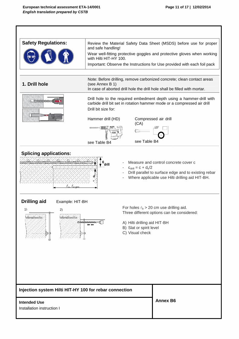
Safety Regulations:
Review the Material Safety Data Sheet (MSDS) before use for proper and safe handling!
Wear well-fitting protective goggles and protective gloves when working with Hilti HIT-HY 100.
Important: Observe the Instructions for Use provided with each foil pack
1. Drill hole Note: Before drilling, remove carbonized concrete; clean contact areas
(see Annex B 1)
In case of aborted drill hole the drill hole shall be filled with mortar.
Drill hole to the required embedment depth using a hammer-drill with carbide drill bit set in rotation hammer mode or a compressed air drill
Drill bit size for:
Hammer drill (HD)
see Table B4
Compressed air drill (CA)
see Table B4
Splicing applications:
- Measure and control concrete cover c
- cdrill = c + ds/2
- Drill parallel to surface edge and to existing rebar
- Where applicable use Hilti drilling aid HIT-BH.
Drilling aid Example: HIT-BH
For holes b > 20 cm use drilling aid.
Three different options can be considered:
A) Hilti drilling aid HIT-BH
B) Slat or spirit level
C) Visual check
drill
v, e,ges.
1) 2)
d
s
European technical assessment ETA-14/0001
English translation prepared by CSTB
Page 12 of 17 | 12/02/2014
Injection system Hilti HIT-HY 100 for rebar connection
Intended Use
Installation instruction II
Annex B7
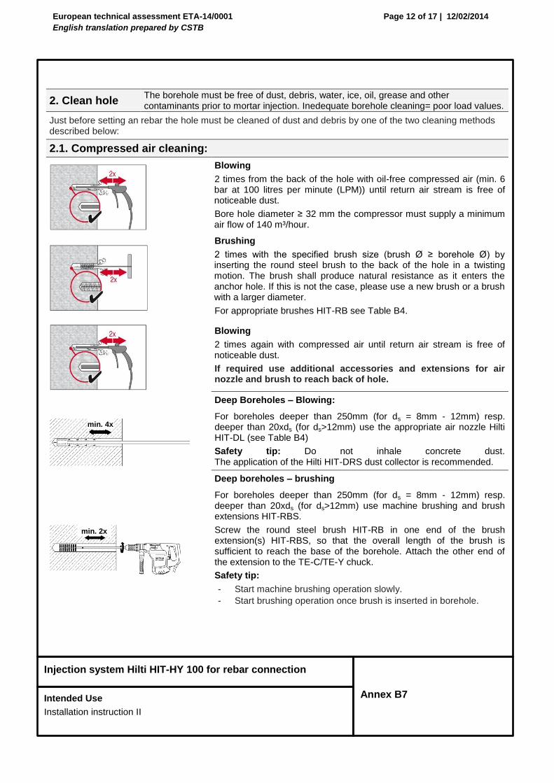
2. Clean hole The borehole must be free of dust, debris, water, ice, oil, grease and other contaminants prior to mortar injection. Inedequate borehole cleaning= poor load values.
Just before setting an rebar the hole must be cleaned of dust and debris by one of the two cleaning methods described below:
2.1. Compressed air cleaning:
Blowing
2 times from the back of the hole with oil-free compressed air (min. 6 bar at 100 litres per minute (LPM)) until return air stream is free of noticeable dust.
Bore hole diameter ≥ 32 mm the compressor must supply a minimum air flow of 140 m³/hour.
Brushing
2 times with the specified brush size (brush Ø ≥ borehole Ø) by inserting the round steel brush to the back of the hole in a twisting motion. The brush shall produce natural resistance as it enters the anchor hole. If this is not the case, please use a new brush or a brush with a larger diameter.
For appropriate brushes HIT-RB see Table B4.
Blowing
2 times again with compressed air until return air stream is free of noticeable dust.
If required use additional accessories and extensions for air nozzle and brush to reach back of hole.
Deep Boreholes – Blowing:
For boreholes deeper than 250mm (for ds = 8mm - 12mm) resp. deeper than 20xds (for ds>12mm) use the appropriate air nozzle Hilti HIT-DL (see Table B4)
Safety tip: Do not inhale concrete dust. The application of the Hilti HIT-DRS dust collector is recommended.
Deep boreholes – brushing
For boreholes deeper than 250mm (for ds = 8mm - 12mm) resp. deeper than 20xds (for ds>12mm) use machine brushing and brush extensions HIT-RBS.
Screw the round steel brush HIT-RB in one end of the brush extension(s) HIT-RBS, so that the overall length of the brush is sufficient to reach the base of the borehole. Attach the other end of the extension to the TE-C/TE-Y chuck.
Safety tip:
- Start machine brushing operation slowly.
- Start brushing operation once brush is inserted in borehole.
min. 4x
min. 2x
European technical assessment ETA-14/0001
English translation prepared by CSTB
Page 13 of 17 | 12/02/2014
Injection system Hilti HIT-HY 100 for rebar connection
Intended Use
Installation instruction III
Annex B8
2.2. Manual cleaning: Manual cleaning is permitted for hammer drilled boreholes up to hole
diameters d0 ≤ 18mm and depths v resp. e,ges. ≤ 160 mm.
Blowing 4 strokes with Hilti blow-out pump from the back of the hole until return air stream is free of noticeable dust.
Brushing 4 times with the specified brush size (brush diameter ≥ borehole diameter d0) by inserting the round steel wire brush to the back of the hole with a twisting motion. The brush shall produce natural resistance as it enters the anchor hole. If this is not the case, please use a new brush or a brush with a larger diameter.
For appropriate Brushes HIT-RB see Table B4.
Blowing 4 strokes with Hilti blow-out pump from the back of the hole until return air stream is free of noticeable dust
Manual Cleaning (MC): Hilti hand pump recommended for blowing out bore holes with diameters d0 ≤ 18 mm and bore hole depth h0 ≤ 160 mm.
European technical assessment ETA-14/0001
English translation prepared by CSTB
Page 14 of 17 | 12/02/2014
Injection system Hilti HIT-HY 100 for rebar connection
Intended Use
Installation instruction IV
Annex B9
3. Rebar preparation and foil pack preparation
Before use, make sure the rebar is dry and free of oil or other residue.
Mark the embedment depth on the rebar
(e.g. with tape ) v
Insert Rebar in borehole, to verify hole and setting depth v resp.
e,ges
Injection system preparation.
- Observe the Instruction for Use of the dispenser.
- Insert foil pack into foil pack holder and swing holder into the dispenser.
Discard initial adhesive. The foil pack opens automatically as dispensing is initiated. Depending on the size of the foil pack an initial amount of adhesive has to be discarded.
Discard quantities are:
2 strokes for 330 ml foil pack,
3 strokes for 500 ml foil pack,
4 strokes <5°C for 330/500 ml foil pack,
4. Inject mortar into borehole Forming air pockets shall be avoided.
Injection method for borehole depth ≤ 250 mm:
Inject the mortar from the back of the hole towards the front and slowly withdraw the mixing nozzle step by step after each trigger pull.
Fill holes approximately 2/3 full, or as required to ensure that the annular gap between the rebar and the concrete is completely filled with adhesive over the embedment length.
After injecting, depressurize the dispenser by pressing the release trigger. This will prevent further mortar discharge from the mixing nozzle.
Embedment mark
European technical assessment ETA-14/0001
English translation prepared by CSTB
Page 15 of 17 | 12/02/2014
Injection system Hilti HIT-HY 100 for rebar connection
Intended Use
Installation instruction V
Annex B10
4. Inject mortar into borehole Forming air pockets shall be avoided.
Injection method for borehole depth > 250 mm or overhead applications:
Assemble mixing nozzle, extension(s) and piston plug HIT-SZ (see Table B4)
For combinations of several injection extensions use coupler HIT-VL K. A substitution of the injection extension for a plastic hose or a combination of both is permitted.
The combination of HIT-SZ piston plug with HIT-VL 16 pipe and then HIT-VL 16 tube support proper injection.
Mark the required mortar level m and embedment depth b
resp. e,ges with tape or marker on the injection extension.
A) Estimation: m = 1/3 ∙v resp. m = 1/3 ∙ e,ges B) Precise formula for optimum mortar volume:
[mm]0,2)-d
d(1,2
2
0
2
s
×resp.= e,gesvm
When using a piston plug HIT-SZ continue injection until the
mortar level mark m becomes visible.
Insert piston plug to back of the hole. Begin injection allowing the pressure of the injected adhesive mortar to push the piston plug towards the front of the hole.
Fill holes approximately 2/3 full, or as required to ensure that the annular gap between the rebar and the concrete is completely filled with adhesive over the embedment length.
After injecting, depressurize the dispenser by pressing the release trigger. This will prevent further mortar discharge from the mixing nozzle.
Maximum embedment depth see B4.
Piston plug HIT-SZ
Injection extension HIT-VL
Mortar level mark
v., e,ges
European technical assessment ETA-14/0001
English translation prepared by CSTB
Page 16 of 17 | 12/02/2014
Injection system Hilti HIT-HY 100 for rebar connection
Intended Use
Installation instruction VI
Annex B11
5. Insert rebar
For ease installation insert the rebar slowly twisted into the borehole until the embedment mark is at the concrete surface level.
Overhead application: During insertion of the rebar mortar might flow out of the bore hole. For collection of the flowing mortar HIT-OHC may be used. Support the rebar and secure it from falling till mortar started to harden, e.g. using HIT-OHW
After installing the rebar the annular gap must be completely filled with mortar. Proper installation
• Desired anchoring embedment is reached lv:
Embedment mark at concrete surface.
• Excess mortar flows out of the borehole after the rebar has been fully inserted until the embedment mark.
• Overhead application: Support the rebar and secure it from falling till mortar started to harden.
Observe the working time “twork”, which varies according to temperature of base material. Minor adjustments to the rebar position may be performed during the working time “twork” see Table B3.
Full load may be applied only after the curing time “tcure“ has elapsed (see Table B3)
Excess mortar
v
Embedment mark
Embedment mark
European technical assessment ETA-14/0001
English translation prepared by CSTB
Page 17 of 17 | 12/02/2014
Injection system Hilti HIT-HY 100 for rebar connection
Performances
Design values of ultimate bond resistance fbd
Annex C1
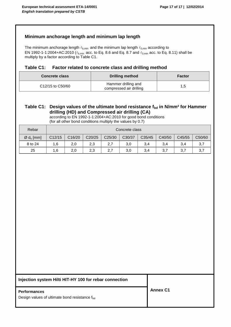
Minimum anchorage length and minimum lap length The minimum anchorage length b,min and the minimum lap length 0,min according to
EN 1992-1-1:2004+AC:2010 (b,min acc. to Eq. 8.6 and Eq. 8.7 and 0,min acc. to Eq. 8.11) shall be multiply by a factor according to Table C1.
Table C1: Factor related to concrete class and drilling method
Concrete class Drilling method Factor
C12/15 to C50/60 Hammer drilling and
compressed air drilling 1,5
Table C1: Design values of the ultimate bond resistance fbd in N/mm² for Hammer drilling (HD) and Compressed air drilling (CA) according to EN 1992-1-1:2004+AC:2010 for good bond conditions (for all other bond conditions multiply the values by 0.7)