ED Decision 2012/009/R 28/06/2012 Annex II ETSO- C55a Date: 05.07.2012 Page 1 of 83 European Aviation Safety Agency European Technical Standard Order Subject: Fuel and Oil Quantity Instruments 1 - Applicability This ETSO gives the requirements which Fuel and Oil Quantity Instruments that are manufactured on or after the date of this ETSO must meet in order to be identified with the applicable ETSO marking. 2 - Procedures 2.1 - General Applicable procedures are detailed in CS-ETSO Subpart A. 2.2 - Specific None. 3 - Technical Conditions 3.1 - Basic 3.1.1 - Minimum Performance Standard Standards set forth in the SAE AS 405BC, Fuel and oil quantity Instruments, dated July 2001, as amended and supplemented by this ETSO: (i) Conformance with the following paragraphs of AS 405BC is not required: 3.1; 3.1.1, 3.1.2, 3.2 and 4.2.1. (ii) Substitute the following for paragraph 7: „Performance tests: The following tests, in addition to any others deemed necessary by the manufacturer, shall be the basis for determining compliance with the performance requirements of this standard“. 3.1.2 - Environmental Standard See CS-ETSO Subpart A paragraph 2.1. As specified in the SAE Aerospace Standard AS 405 C. 3.1.3 – Computer Software See CS-ETSO Subpart A paragraph 2.2. 3.1.4 - Electronic Hardware Qualification See CS-ETSO Subpart A paragraph 2.3.
Transcript
ED Decision 2012/009/R
28/06/2012
Annex II
ETSO- C55a
Date: 05.07.2012
Page 1 of 83
European
Aviation Safety Agency
European Technical Standard Order
Subject: Fuel and Oil Quantity Instruments
1 - Applicability This ETSO gives the requirements which Fuel and Oil Quantity Instruments that are
manufactured on or after the date of this ETSO must meet in order to be identified with the applicable ETSO marking.
2 - Procedures
2.1 - General
Applicable procedures are detailed in CS-ETSO Subpart A.
2.2 - Specific
None.
3 - Technical Conditions
3.1 - Basic
3.1.1 - Minimum Performance Standard
Standards set forth in the SAE AS 405BC, Fuel and oil quantity Instruments, dated July 2001, as amended and supplemented by this ETSO:
(i) Conformance with the following paragraphs of AS 405BC is not required: 3.1; 3.1.1, 3.1.2, 3.2 and 4.2.1.
(ii) Substitute the following for paragraph 7: „Performance tests: The following tests, in addition to any others deemed necessary by the manufacturer, shall be the basis for determining compliance with the performance requirements of this standard“.
3.1.2 - Environmental Standard
See CS-ETSO Subpart A paragraph 2.1.
As specified in the SAE Aerospace Standard AS 405 C.
3.1.3 – Computer Software
See CS-ETSO Subpart A paragraph 2.2.
3.1.4 - Electronic Hardware Qualification
See CS-ETSO Subpart A paragraph 2.3.
ED Decision 2012/009/R
28/06/2012
Annex II
ETSO- C55a
Date: 05.07.2012
Page 2 of 83
3.2 - Specific
3.2.1 Failure Condition Classification See CS-ETSO Subpart A paragraph 2.4.
The failure condition classification will depend on the system on which the fuel and oil quantity instrument is installed. The classification must be determined by the safety assessment conducted as part of the installation approval. Develop each fuel and oil quantity instrument to at least the design assurance level assigned to the system on which the fuel and oil quantity instrument is installed.
4 - Marking
4.1 - General
Marking as detailed in CS-ETSO Subpart A paragraph 1.2.
4.2 - Specific
a. Mark at least one major component permanently and legibly with all the information
in SAE AS405C, Section 3.2 (except paragraph 3.2.b). Also, mark the component with
the following information:
(1) The basic type and accuracy classification, and
(2) The fluids for which the instrument is substantiated
b. If the fuel and oil quantity instrument includes a digital computer, then the part
number must include hardware and software identification. Or, you can use a
separate part number for hardware and software. Either way, you must include a
means to show the modification status.
NOTE: Similar software versions, approved for different software levels, must be
differentiated by part number.
5 - Availability of Referenced Document See CS-ETSO Subpart A paragraph 3.
ED Decision 2012/009/R
28/06/2012
Annex II
ETSO-C62e
Date: 05.07.2012
Page 3 of 83
European Aviation
Safety Agency
European Technical Standard Order
Subject: Aircraft Tyres
1 - Applicability This ETSO gives the requirements which tyres excluding tailwheel tyres that are
manufactured on or after the date of this ETSO must meet in order to be identified with the applicable ETSO marking.
2 - Procedures
2.1 - General
Applicable procedures are detailed in CS-ETSO Subpart A.
2.2 - Specific
None.
3 - Technical Conditions
3.1 - Basic
3.1.1 - Minimum Performance Standard
Standards set forth in the attached Appendix 1, “Federal Aviation Administration Standard for Aircraft Tyres”, dated 29/09/2006.
3.1.2 - Environmental Standard
As stated in the Federal Aviation Administration Standard.
3.1.3 – Computer Software
None
3.1.4 - Electronic Hardware Qualification
None
3.2 - Specific None
3.2.1 Failure Condition Classification
N/A
ED Decision 2012/009/R
28/06/2012
Annex II
ETSO-C62e
Date: 05.07.2012
Page 4 of 83
4 - Marking
4.1 - General
Marking as detailed in CS-ETSO Subpart A paragraph 1.2.
4.2 - Specific
1. Balance marker, consisting of a red dot, on the sidewall of the tire immediately above
the bead to indicate the lightweight point of the tire.
2. Production date code (may be included in the established serial number).
3. Ply rating must be established. Submit these ratings to the Tire and Rim Association,
Inc. (TRA) or European Tyre and Rim Technical Organization (ETRTO). If the ply rating
is marked on the tire, the load rating marked on the tire must be consistent with the
ply rating established.
A.1.1.1.1.1.1.1.1 NOTE: for a new programme aircraft, define new tire
dimensions and submit them to ETRTO for publication in the ETRTO Data Book.
You do not have to wait until your submitted dimensions are incorporated into
the Data Book before applying for the ETSO.
4. Serial number: the plant code and production date code may be included.
5. Size and load ratings, established and identified in a timely manner in the TRA Aircraft
Year Book, latest edition or in the ETRTO Aircraft Tyre and Rim Data Book, latest
revision. See the NOTE at paragraph g.
6. Skid depth, marked in inches to the nearest one-hundredth as defined in appendix 1.
7. Speed rating, in MPH and as identified in appendix 1, paragraph 4.b that is equal to or
less than the speed at which the tire has been qualified.
8. Tire type. Mark tires requiring a tube with the words “Tube type.”
9. Non-re-treadable tires must be marked accordingly.
5 - Availability of Referenced Document See CS-ETSO Subpart A paragraph 3.
ED Decision 2012/009/R
28/06/2012
Annex II
ETSO-C62e
Appendix 1
Date: 05.07.2012
Page 5 of 83
APPENDIX 1. FAA STANDARD FOR AIRCRAFT TIRES
1. PURPOSE. Minimum performance standards for new and re-qualified radial and bias tires,
excluding tailwheel tires, to be identified as meeting the standards of ETSO-C62e.
2. SCOPE. Minimum performance standards apply to aircraft tires having speed and load
ratings based on the speeds and loads to which the tires have been tested.
3. DEFINITIONS.
Bias tire: a pneumatic tire whose ply cords extend to the beads and are laid at alternate
angles substantially less than 90º to the centerline of the tread. May also have a bias belted
tire with a circumferential belt.
Radial tire: a pneumatic tire whose ply cords extend to the beads and are laid approximately
at 90º to the centerline of the tread, the carcass being stabilised by an essentially inextensible
circumferential belt.
Load rating: maximum permissible static load at a specific inflation pressure. Use the rated
load combined with the rated inflation pressure when selecting tires for application to an
aircraft, and for testing to the performance requirements of this ETSO.
Rated inflation pressure: specified unloaded inflation pressure which will result in the tire
deflecting to the specified static loaded radius when loaded to its rated load against a flat
surface.
Static loaded radius (SLR): perpendicular distance between the axle centerline and a flat
surface for a tire initially inflated to the unloaded rated inflation pressure and then loaded to its
rated load.
Ply rating: an index of tire strength from which a rated inflation pressure and its
corresponding maximum load rating are determined for a specific tire size.
Speed rating: maximum ground speed at which the tire has been tested in accordance with
this ETSO.
Skid depth: distance between the tread surface and the bottom of the deepest groove as
measured in the mold.
4. DESIGN AND CONSTRUCTION .
a. General Standards. Tires selected for use on a specific aircraft must demonstrate suitability
through appropriate laboratory simulations described in paragraphs 5.a or 5.b of this appendix,
as appropriate. Determine material suitability by:
(1) Temperature: show by tests or analysis that the physical properties of the tire materials
are not degraded by exposure to temperature extremes of -40°C (-40ºF) and +71,1°C
(+160ºF) for a period of not less than 24 hours at each extreme.
ED Decision 2012/009/R
28/06/2012
Annex II
ETSO-C62e
Appendix 1
Date: 05.07.2012
Page 6 of 83
(2) Wheel rim heat: substantiate by the applicable tests or show by analysis that the physical
properties of the tire materials have not been degraded by exposure of the tire to a wheel-
bead seat temperature of not lower that 148,9°C (300°F) for at least 1 hour, except that low-
speed tires or nose-wheel tires may be tested or analysed at the highest wheel-bead seat
temperatures expected to be encountered during normal operations.
b. Speed Rating. See Table 1 below for applicable dynamometer test speeds for corresponding
maximum takeoff ground speeds. For takeoff speeds over 245 mph, the tire must be tested to
the maximum applicable load-speed-time requirements and identified with the proper speed
rating.
TABLE 1. Applicable Dynamometer Test Speeds
Max Takeoff Speed
Mph at liftoff over:
But not over: Max takeoff Speed
Of Aircraft Max Tire
mph:
Min Dynamometer
Speed (Figures 1, 2
or 3) Min Tire mph:
0 120 120 120
120 160 160 160
160 190 190 190
190 210 210 210
210 225 225 225
225 235 235 235
235 245 245 245
c. Overpressure. The tire must successfully withstand a hydrostatic pressure of at least four
times its rated inflation pressure for 3 seconds without bursting.
d. Helicopter tires. You may use aircraft tires qualified according to this ETSO on helicopters.
In such cases for standard tires, you may increase the maximum static load rating by a factor
of 1.5 with a corresponding increase in rated inflation pressure without additional qualification
testing (round loads to the nearest 10 lbs and inflation pressures to the nearest whole psi.). If
significant taxi distance is expected, these guidelines may not apply. Consult tire and rim
manufacturers for appropriate tire size selection. Maximum permissible inflation for aircraft
tires used on helicopters is 1.8 times the rated inflation pressure.
e. Dimensions. Maintain the tire size (outside diameter, shoulder diameter, section and
shoulder width), within specified tolerances.
NOTE: for a new programme aircraft, define new tire dimensions and submit them to TRA for
publication in the TRA Data Book. You do not have to wait until your submitted dimensions are
incorporated into the Data Book before applying for the ETSO.
ED Decision 2012/009/R
28/06/2012
Annex II
ETSO-C62e
Appendix 1
Date: 05.07.2012
Page 7 of 83
(1) Outside diameter, shoulder diameter, section width and shoulder width: For the bias ply
tire, outside diameter and section width are specified to a maximum and minimum value after
a 12 hour growth period at rated inflation pressure. Shoulder diameter and width dimensions
are specified to a maximum value after a 12-hour growth period at rated inflation pressure.
Radial tire dimensions are limited by the grown tire envelope according to the static loaded
radius (SLR) requirements in paragraph 4.e.(3) below.
(2) Due to the increased inflation pressures permitted when using an aircraft tire in a
helicopter application, we permit tire dimensions to be 4% larger.
(3) Static loaded radius (SLR):
(a) Bias tires: provide the nominal SLR. The actual SLR is determined on a new tire stretched
for a minimum of 12 hours at rated inflation pressure.
(b) Radial tires: provide the nominal SLR. The actual SLR of a radial tire is determined at rated
inflation pressure after running 50 takeoffs, following paragraph 5.a.(2) requirements.
(4) Helicopter tires: maximum dimensions for new tires used on helicopters are 4% larger
than maximum aircraft tire dimensions. (In calculating maximum overall and shoulder
diameters, rim diameter should be deducted before applying 4%.)
f. Inflation retention. After an initial 12-hour minimum stabilisation period at rated inflation
pressure, the tire must retain the inflation pressure with a loss of pressure not exceeding 5%
of the initial pressure for 24 hours. Measure the ambient temperature at the start and finish of
the test to ensure that any pressure change was not caused by an ambient temperature
change.
g. Balance. Test all tires for static unbalance. A balance marker, consisting of a red dot, must
be affixed on the sidewall of the tire immediately above the bead to indicate the lightweight
point of the tire. The dot must remain for any period of storage plus the original tread life of
the tire.
(1) Auxiliary tires (not main or tailwheel tires): the moment of static unbalance (M) for
auxiliary tires shall not be greater than the value determined using this equation:
M = 0.025D2
Round the computed equation values to the next lower whole number where M is in inch-
ounces and D is the standardised maximum new tire inflated outside diameter in inches. Your
design must include requirements to measure the level of unbalance on each tire, and
approved procedures to correct the unbalance within the above limits if necessary.
(2) All main tires and all tires with 46-inch and larger outside diameter: the moment of static
unbalance (M) for main tires shall not be greater than the value determined using this
equation:
M = 0.035D2
ED Decision 2012/009/R
28/06/2012
Annex II
ETSO-C62e
Appendix 1
Date: 05.07.2012
Page 8 of 83
Round the computed equation values to the next lower whole number where M is in inch-
ounces and D is the standardised maximum new tire inflated outside diameter in inches. Your
design must include requirements to measure the level of unbalance on each tire, and
approved procedures to correct the unbalance within the above limits if necessary.
5. TIRE TEST REQUIREMENTS.
a. Use a single test specimen for a qualification test. The tire must withstand the following
dynamometer cycles without detectable signs of deterioration, other than normal expected
tread surface abrasion, except when the overload takeoff condition is run last (see paragraph
5.a.(8) below).
(1) Dynamometer cycle requirements: all aircraft tires must satisfactorily withstand 58
dynamometer cycles as a demonstration of overall performance, plus 3 overload dynamometer
cycles as a demonstration of the casing’s capability under overload. The 58 dynamometer
cycles consists of 50 takeoff cycles, per 5.a.(2), and 8 taxi cycles, per 5.a.(7). The overload
cycles consist of 2 taxi cycles, per 5.a.(7) at 1.2 times rated load and 1 overload takeoff cycle
per 5.a.(8) starting at 1.5 times rated load. Run the dynamometer cycles in any order.
However, if the overload takeoff cycle is not run last, the tire must not show detectable signs
of deterioration after the cycle completion, other than normal expected tread surface abrasion.
(2) Takeoff cycles: the 50 takeoff cycles shall realistically simulate tire performance during
runway operations for the most critical combination of takeoff weight and speed, and aircraft
center-of-gravity position. When determining the most critical combination of the above, be
sure to account for increased speeds resulting from high field elevation operations and high
ambient temperatures, if applicable. Specify the appropriate load-speed-time data or
parameters that correspond to the test envelope in which the tire is to be tested. Figures 1, 2,
and 3 are graphic representations of the test. Starting at zero speed, load the tire against the
dynamometer flywheel. The test cycles must simulate one of the curves illustrated in Figure 1
or 2 (as applicable to speed rating), or Figure 3.
Figure 1 defines a test cycle that applies to any aircraft tire with a speed rating of 120
mph or 160 mph.
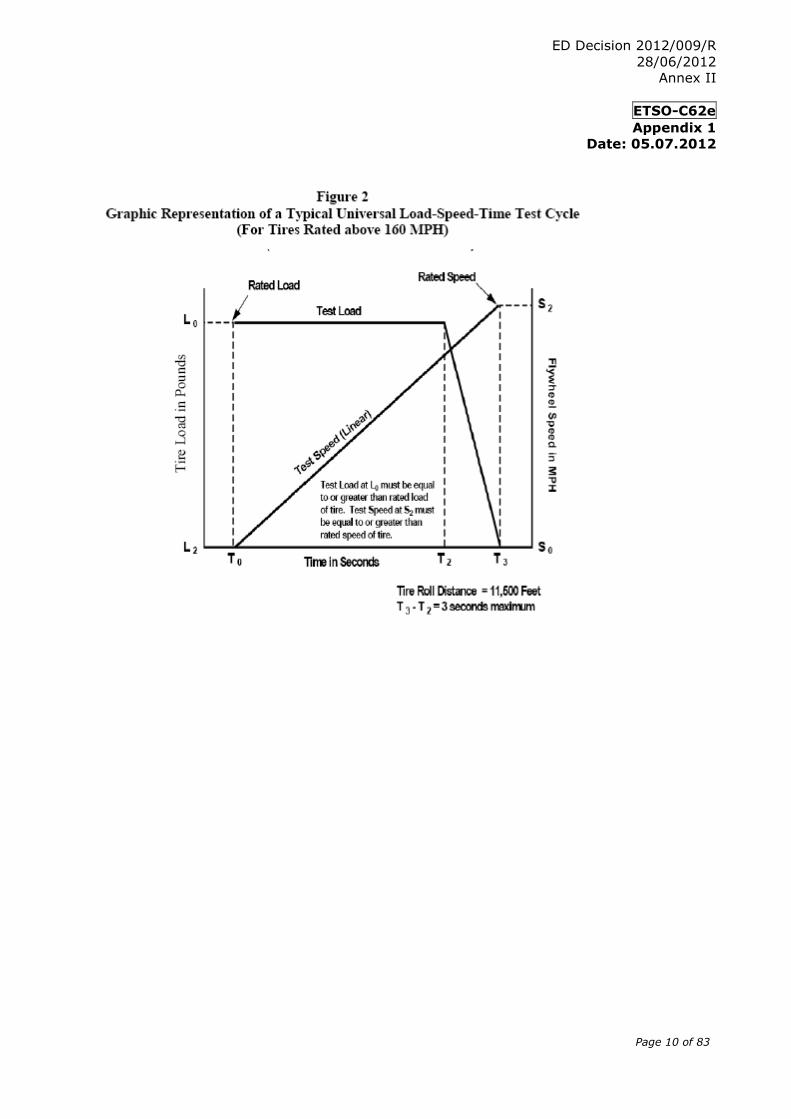
Figure 2 defines a test cycle that applies to any aircraft tire with a speed rating greater
than 160 mph.
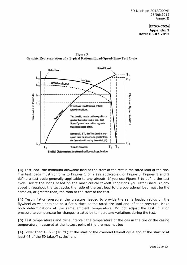
Figure 3 defines a test cycle that applies for any speed rating, is based on the most
critical takeoff loads, speeds, and distances, and is aircraft specific.
ED Decision 2012/009/R
28/06/2012
Annex II
ETSO-C62e
Appendix 1
Date: 05.07.2012
Page 9 of 83
Symbol Definitions (Figures 1, 2, and 3)
L0 Tire load (lbs) at start of takeoff (not less than the load rating), Figures 1, 2, and 3.
L01 Tire load (lbs) at start of takeoff for the operational load curve, Figure 3.
L1 Tire load (lbs) at rotation, Figures 1 and 3.
L11 Tire load (lbs), Figure 3.
L2 Tire load at liftoff, 0 lbs, Figures 1, 2, and 3.
S0 Zero (0) mph, Figures 1, 2, and 3.
S1 Speed at rotation in mph, Figure 3.
S2 Tire speed at liftoff in mph (not less than the speed rating), Figures 1, 2, and 3.
T0 Time at start of takeoff, 0 s, Figures 1, 2, and 3.
T1 20 seconds, Figure 1.
T2 Time to rotation in seconds, Figures 1, 2, and 3.
T3 Time to liftoff in seconds, Figures 1, 2, and 3.
ED Decision 2012/009/R
28/06/2012
Annex II
ETSO-C62e
Appendix 1
Date: 05.07.2012
Page 10 of 83
ED Decision 2012/009/R
28/06/2012
Annex II
ETSO-C62e
Appendix 1
Date: 05.07.2012
Page 11 of 83
(3) Test load: the minimum allowable load at the start of the test is the rated load of the tire.
The test loads must conform to Figures 1 or 2 (as applicable), or Figure 3. Figures 1 and 2
define a test cycle generally applicable to any aircraft. If you use Figure 3 to define the test
cycle, select the loads based on the most critical takeoff conditions you established. At any
speed throughout the test cycle, the ratio of the test load to the operational load must be the
same as, or greater than, the ratio at the start of the test.
(4) Test inflation pressure: the pressure needed to provide the same loaded radius on the
flywheel as was obtained on a flat surface at the rated tire load and inflation pressure. Make
both determinations at the same ambient temperature. Do not adjust the test inflation
pressure to compensate for changes created by temperature variations during the test.
(5) Test temperatures and cycle interval: the temperature of the gas in the tire or the casing
temperature measured at the hottest point of the tire may not be:
(a) Lower than 40,6°C (105ºF) at the start of the overload takeoff cycle and at the start of at
least 45 of the 50 takeoff cycles, and
ED Decision 2012/009/R
28/06/2012
Annex II
ETSO-C62e
Appendix 1
Date: 05.07.2012
Page 12 of 83
(b) Lower than 48,9°C (120ºF) at the start of at least 9 of the 10 taxi cycles.
For the remaining cycles, the contained gas or casing temperature may not be lower than
26,7°C (80ºF) at the start of each cycle. Rolling the tire on the dynamometer flywheel is an
acceptable method for obtaining the minimum starting temperature.
(6) Dynamometer takeoff cycle speeds: see Table 1 for the dynamometer test speeds for the
corresponding maximum aircraft takeoff speeds.
(7) Taxi cycles: tire must withstand 10 taxi cycles on a dynamometer under the test
conditions in Table 2 below.
TABLE 2. Test Conditions
Number of
Taxi Runs
Min Tire Load
(lbs)
Min Speed
(mph)
Tire speed rating
120/160 mph
Min Rolling
Distance (ft)
Tire speed rating
Over 160 mph
Min Rolling
Distance (ft)
8 Rated 40 25,000 35,000
2 1.2 x Rated 40 25,000 35,000
(8) Overload takeoff cycle: the overload takeoff cycle shall duplicate the test described in
paragraph 5.a.(2) with the test load increased by a factor of 1.5 throughout. Good condition
of the tire tread is not required after completion of this test cycle, if you run this test last. If
the overload takeoff cycle is not run last, the tire must withstand the cycle without detectable
signs of deterioration, other than normal expected tread surface abrasion.
(9) Diffusion test: after completing the 61 test cycles, the tire must retain the inflation
pressure to within 10% of the initial test pressure for a period of 24 hours. Measure the
ambient temperature at the start and finish of this test to ensure that any pressure change
was not caused by an ambient temperature change.
(10) Tire/wheel slippage: tires should not slip on the wheel rim during the first five
dynamometer cycles. Any slippage that subsequently occurs must not damage the tube valve
of tube type tires, or the gas seal of the tire bead of tubeless tires.
b. Alternate qualification procedures: 120 mph rated tires. For 120 mph speed rating tires, you
may use the following variable mass flywheel procedure:
(1) Test load: load must meet or exceed the tire rated load throughout the entire test roll
distance.
(2) Test inflation pressure: pressure needed to provide the same loaded radius on the flywheel
as was obtained on a flat surface at the rated tire load and inflation pressure. Make both
ED Decision 2012/009/R
28/06/2012
Annex II
ETSO-C62e
Appendix 1
Date: 05.07.2012
Page 13 of 83
determinations at the same ambient temperature. Do not adjust the test inflation pressure to
compensate for changes created by temperature variations during the test.
(3) Temperature and cycle interval: the temperature of the gas in the tire, or the casing
temperature measured at the hottest point of the tire, may not be lower than 40,6°C (105ºF)
at the start of at least 180 of the 200 landing cycles. For the remaining cycles, the contained
gas or casing temperature may not be lower than 26,7°C (80ºF) at the start of each cycle.
Rolling the tire on the dynamometer is an acceptable method for obtaining the minimum
starting temperature.
(4) Kinetic energy: calculate the kinetic energy of the flywheel to be absorbed by the tire
using this equation:
KE = CW(V 2) = Kinetic energy (ft-lbs)
where
C = 0.0113
W = Load rating of the tire (lbs)
V = 120 mph
(5) Dynamometer cycle requirements: tire must satisfactorily withstand 200 landing cycles on
a variable mass dynamometer flywheel. If you cannot use the exact number of flywheel plates
to obtain the calculated kinetic energy value, select a greater number of plates and adjust the
dynamometer speed to obtain the required kinetic energy. Divide the total number of
dynamometer landings into two equal parts having the speed ranges provided in paragraphs
5.b.(5)(a) and 5.b.(5)(b).
(a) Low speed landings: in the first series of 100 landings, the maximum landing speed is
90 mph and the minimum unlanding speed is 0 mph. Adjust the landing speed so the tire will
absorb 56% of the kinetic energy calculated using the equation in paragraph 5.b.(4) above. If
the adjusted landing speed is calculated to be less than 80 mph, then determine the landing
speed by adding 28% of the calculated kinetic energy (see paragraph 5.b.(4) above) to the
flywheel kinetic energy at 64 mph, and determine the unlanding speed by subtracting 28% of
the calculated kinetic energy from the flywheel kinetic energy at 64 mph.
(b) High speed landings: in the second series of 100 landings, the minimum landing speed is
120 mph and the nominal unlanding speed is 90 mph. Adjust the unlanding speed as needed
to ensure that the tire will absorb 44% of the calculated kinetic energy (see paragraph 5.b.(4)
above).
6. REQUALIFICATION TESTS.
a. Re-qualify altered tires, with changes in materials, design and/or manufacturing processes
that could adversely affect the performance and reliability, to the dynamometer tests
described under paragraph 5. Some examples include (1) or (2) below, or both:
(1) Changes in casing construction, such as the number of plies and/or bead bundles, ply cord
makeup (material, denier, number of strands) and configuration (radial and bias).
ED Decision 2012/009/R
28/06/2012
Annex II
ETSO-C62e
Appendix 1
Date: 05.07.2012
Page 14 of 83
(2) Changes in tread construction, such as number or composition of tread reinforcing and/or
protector plies, tread compound formulations, number and location of tread grooves, and an
increase in skid depth.
b. Re-qualification by similarity (based on load rating). Re-qualifying a given load rated tire
due to a change in material or tread design, automatically qualifies the same changes in a
lesser load tire of the same size, speed rating, and skid depth, if:
(1) The lesser load rated tire was qualified to the applicable requirements specified in this
ETSO, and
(2) The ratio of qualification test load to rated load for the lesser load rated tire does not
exceed the same ratio to the higher load rated tire at any given test condition.
c. Re-qualification by similarity (blanket change). You can gain re-qualification of any change
that affects all sizes by similarity, if:
(1) Five representative sizes, including tires of the highest load rating, speed rating and
angular velocity, were qualified to the minimum performance standard with the change, and
(2) You submit data supporting the change in the listed sizes to EASA.
ED Decision 2012/009/R
28/06/2012
Annex II
ETSO-C90d
Date: 05.07.2012
Page 15 of 83
European Aviation Safety Agency
European Technical Standard Order
Subject: Cargo Pallets, Nets and Containers (Unit Load Devices)
1 - Applicability This ETSO gives the requirements which Cargo Unit Load Devices that are
manufactured on or after the date of this ETSO must meet in order to be identified with the applicable ETSO marking.
2 - Procedures
2.1 - General
Applicable procedures are detailed in CS-ETSO Subpart A.
2.2 - Specific
None.
3 - Technical Conditions
3.1 - Basic
3.1.1 - Minimum Performance Standard
For new models of Type I ULDs standards set forth in standard of Aerospace Industries
Association of America, Inc. (AIA), National Aerospace Standard, NAS 3610, “Cargo
Unit Load Devices.- Specification for,” Revision 10, dated November 1, 1990.
When using NAS 3610 Revision 10, the following errors must be corrected:
- in lieu of Figure 31, sheet 87, substitute Figure 31, sheet 88;
- in lieu of Figure 31, sheet 88, substitute Figure 32, sheet 87 of NAS 3610 Revision 8
dated April 1987
For new models of Type II ULDs standards set forth in the Society of Automotive Engineers, Inc. (SAE) Aerospace Standard (AS) 36100, “Air Cargo Unit Load Devices - Performance Requirements and Test Parameters”, Revision A, dated April 2006.
For Type I and II ULDs, the standards set forth in SAE AS 36102, Air Cargo Unit Load Devices - Testing Methods, dated March 2005 are applicable.
3.1.2 - Environmental Standard
ED Decision 2012/009/R
28/06/2012
Annex II
ETSO-C90d
Date: 05.07.2012
Page 16 of 83
See CS-ETSO Subpart A paragraph 2.1.
3.1.3 – Computer Software
None
3.1.4 - Electronic Hardware Qualification
None
3.2 - Specific
Environmental degradation due to ageing, ultra-violet (UV)-exposure, weathering, etc.
for any non-metallic materials used in the construction of pallets, nets and containers
must be considered.
In lieu of NAS 3610 Rev. 10, paragraph 3.7 and SAE AS 36100 Rev. A, paragraph
4.7 use the following paragraph which provides the fire protection requirements for
ULDs:
The materials used in the construction of pallets, nets and containers must meet the
appropriate provisions in CS-25, Appendix F, Part I, paragraph (a)(2)(iv).
Textile Performance: See SAE Aerospace Information Report (AIR) 1490B,
Environmental Degradation of Textiles, dated December 2007, for available data for
textile performance when exposed to environmental factors. These data shall be taken
into account for consideration of the effects of environmental degradation on nets
commensurate with the expected storage and service life to satisfy SAE AS 36100
Rev. A, paragraph 4.11.
NOTE: Environmental degradation data other than that documented in AIR1490B may
be used if substantiated by the applicant and approved by EASA.
None
3.2.1 Failure Condition Classification N/A
4 - Marking
4.1 - General
Marking is detailed in CS-ETSO Subpart A paragraph 1.2.
4.2 - Specific
In addition, the following information shall be legibly and permanently marked on the ULD:
1. The identification of the article in the code system explained in
a. NAS 3610, Revision 10, paragraph 1.2.1, for Type I ULDs.
b. SAE AS 36100, Rev. A, paragraph 3.5 for Type II ULDs.
2. The nominal weight of the article in kilogram and pound in the format: Weight: …kg (…lb)
3. If the article is not omni-directional, the words “FORWARD”, “AFT”, and “SIDE” must be conspicuously and appropriately placed.
4. The manufacturer’s serial number of the article, with the option to add the date of manufacture.
5. The burning rate determined for the article under paragraph 3.2 of this ETSO.
6. If applicable, the expiration date in the format “ EXP YYYY-MM” must be marked on the ULD.
5 - Availability of Referenced Document See CS-ETSO Subpart A paragraph 3.
ED Decision 2012/009/R
28/06/2012
Annex II
ETSO-C95a
Date: 05.07.2012
Page 17 of 83
European
Aviation Safety Agency
European Technical Standard Order
Subject: Mach Meters
1 - Applicability This ETSO gives the requirements which Mach Meters that are manufactured on or
after the date of this ETSO must meet in order to be identified with the applicable ETSO marking.
2 - Procedures
2.1 - General
Applicable procedures are detailed in CS-ETSO Subpart A.
2.2 - Specific
None.
3 - Technical Conditions
3.1 - Basic
3.1.1 - Minimum Performance Standard
Standards set forth in the SAE AS 8018A, Mach Meters, dated 01/09/1996.
3.1.2 - Environmental Standard
See CS-ETSO Subpart A paragraph 2.1.
3.1.3 – Computer Software
See CS-ETSO Subpart A paragraph 2.2.
3.1.4 - Electronic Hardware Qualification
See CS-ETSO Subpart A paragraph 2.3.
3.2 - Specific None
3.2.1 Failure Condition Classification See CS-ETSO Subpart A paragraph 2.4.
Failure of the function defined in paragraph 3.1.1 of this ETSO has been determined
to be a major failure condition.
4 – Marking
4.1 - General
ED Decision 2012/009/R
28/06/2012
Annex II
ETSO-C95a
Date: 05.07.2012
Page 18 of 83
Marking as detailed in CS-ETSO Subpart A paragraph 1.2.
4.2 - Specific
None, marking in accordance with AS 8018A addendum 1 section 2 is optional.
5 - Availability of Referenced Document See CS-ETSO Subpart A paragraph 3.
ED Decision 2012/009/R
28/06/2012
Annex II
ETSO-C126a
Date: 05.07.2012
Page 19 of 83
European
Aviation Safety Agency
European Technical Standard Order
Subject: 406MHz Emergency Locator Transmitter
1 - Applicability This ETSO gives the requirements which 406MHz Emergency Locator Transmitter that
are manufactured on or after the date of this ETSO must meet in order to be identified with the applicable ETSO marking.
2 - Procedures
2.1 - General
Applicable procedures are detailed in CS-ETSO Subpart A.
2.2 - Specific
None.
3 - Technical Conditions
3.1 - Basic
3.1.1 - Minimum Performance Standard
Standards set forth in the EUROCAE ED-62A, Minimum Operational Performance Specification for Aircraft Emergency Locator Transmitters 406 MHz and 121.5 MHz (Optional 243 MHz), dated February 2009.
3.1.2 - Environmental Standard
See CS-ETSO Subpart A paragraph 2.1.
3.1.3 – Computer Software
See CS-ETSO Subpart A paragraph 2.2.
3.1.4 - Electronic Hardware Qualification
See CS-ETSO Subpart A paragraph 2.3.
3.2 - Specific
3.2.1 Failure Condition Classification
See CS-ETSO Subpart A paragraph 2.4. Failure of the function defined in paragraph 3.1.1 of this ETSO has been determined to be a minor failure condition.
ED Decision 2012/009/R
28/06/2012
Annex II
ETSO-C126a
Date: 05.07.2012
Page 20 of 83
4 - Marking
4.1 - General
Marking as detailed in CS-ETSO Subpart A paragraph 1.2.
4.2 - Specific
See EUROCAE ED-62A paragraph 2.7.3.None
5 - Availability of Referenced Document See CS-ETSO Subpart A paragraph 3.
ED Decision 2012/009/R
28/06/2012
Annex II
ETSO-C154c
Date: 05.07.2012
Page 21 of 83
European Aviation
Safety Agency
European Technical Standard Order
Subject: Universal Access Transceiver (UAT) Automatic Dependent Surveillance - Broadcast (ADS-B) Equipment Operating on the Frequency of 978 MHz
1 - Applicability
This ETSO gives the requirements which Universal Access Transceiver (UAT) Automatic Dependent Surveillance - Broadcast (ADS-B) Equipment Operating on the Frequency of 978 MHz that are manufactured on or after the date of this ETSO must meet in order to be identified with the applicable ETSO marking.
2 - Procedures
2.1 - General
Applicable procedures are detailed in CS-ETSO Subpart A.
2.2 - Specific
None.
3 - Technical Conditions
3.1 - Basic
3.1.1 - Minimum Performance Standard
Standards set forth in the Radio Technical Commission for Aeronautics (RTCA) Document DO-282B, Minimum Operational Performance Standards for Universal Access Transceiver (UAT) Automatic Dependent Surveillance Broadcast (ADS-B), dated 02/12/2009.
3.1.2 - Environmental Standard
See CS-ETSO Subpart A paragraph 2.1.
3.1.3 – Computer Software
See CS-ETSO Subpart A paragraph 2.2.
3.1.4 - Electronic Hardware Qualification
See CS-ETSO Subpart A paragraph 2.3.
3.2 - Specific
3.2.1 Failure Condition Classification
See CS-ETSO Subpart A paragraph 2.4.
Failure of the function defined in paragraph 3.1.1 of this ETSO has been determined to be a major failure condition.
ED Decision 2012/009/R
28/06/2012
Annex II
ETSO-C154c
Date: 05.07.2012
Page 22 of 83
4 - Marking
4.1 - General
Marking as detailed in CS-ETSO Subpart A paragraph 1.2.
4.2 - Specific
Transmitting and receiving components must be permanently and legibly marked. The
following table explains how to mark components. Find the equipment class in
RTCA/DO-282B, Section 2.1.11.
If component can: Mark it with: Sample marking pattern:
Transmit and receive Equipment class it supports Class A1H or Class A3
Transmit, but not receive Equipment class it supports Class B1 or
Class A3 - Transmit Only
Receive, but not transmit Equipment class it supports Class A2 - Receive Only
Perform the optional
frequency diplexer function
developed under this ETSO
The words “UAT Diplexer,”
Maximum amplitude
attenuation between the
antenna port (A) and UAT port
(U) of the diplexer, and
Maximum amplitude
attenuation between the
antenna port (A) and
transponder port (T) of the
diplexer
UAT Diplexer
A/U -0.x dB
A/T -0.x dB
5 - Availability of Referenced Document See CS-ETSO Subpart A paragraph 3.
ED Decision 2012/009/R
28/06/2012
Annex II
ETSO-C157a
Date: 05.07.2012
Page 23 of 83
European
Aviation Safety Agency
European Technical Standard Order
Subject: Aircraft Flight Information Services-Broadcast (FIS-B) Data Link Systems and Equipment
1 - Applicability
This ETSO gives the requirements which Aircraft Flight Information Services-Broadcast (FIS-B) Data Link Systems and Equipment that are manufactured on or after the date of this ETSO must meet in order to be identified with the applicable ETSO marking.
2 - Procedures
2.1 - General
Applicable procedures are detailed in CS-ETSO Subpart A.
2.2 - Specific
None.
3 - Technical Conditions
3.1 - Basic
3.1.1 - Minimum Performance Standard
This standard apply to equipment intended to display weather and other non-control flight advisory information to pilots in a manner that will enhance their awareness of the flight conditions.
Standards set forth in the Radio Technical Commission for Aeronautics (RTCA) Document DO-267A, Minimum Aviation System Performance Standards (MASPS) for Flight Information Services-Broadcast (FIS-B) Data Link, Rev. A dated 29 April 2004. The standard applies to the equipment classes as defined in the following table 1. Demonstrate the required functional performance under the test conditions specified in RTCA/DO-267A Section 4.
ED Decision 2012/009/R
28/06/2012
Annex II
ETSO-C157a
Date: 05.07.2012
Page 24 of 83
Equipment Class Equipment Name Functionality
1 FIS-B Equipment using Universal Access Transceiver (UAT) and Interoperable with the Surveillance and Broadcast Services (SBS) Provider
RTCA/DO-267A Sections 2 and 3, with amendments per Appendix 1 of this ETSO.
2 FIS-B Equipment not Interoperable with the SBS Provider
RTCA/DO-267A Section 2 (except 2.1.4; 2.2.12; and 2.2.13) and Section 3.8.
Table 1. Equipment Classes for FIS-B
3.1.2 - Environmental Standard
See CS-ETSO Subpart A paragraph 2.1.
3.1.3 – Computer Software
See CS-ETSO Subpart A paragraph 2.2.
3.1.4 - Electronic Hardware Qualification
See CS-ETSO Subpart A paragraph 2.3.
3.2 - Specific
3.2.1 - Failure Condition Classification See CS-ETSO Subpart A paragraph 2.4.
Loss or malfunction of the function defined in paragraph 3.1.1 of this ETSO has been determined to be a minor failure condition.
4 - Marking
4.1 - General
Marking as detailed in CS-ETSO Subpart A paragraph 1.2.
4.2 - Specific
None
5 - Availability of Referenced Document See CS-ETSO Subpart A paragraph 3.
ED Decision 2012/009/R
28/06/2012
Annex II
ETSO-C157a
Appendix 1
Date: 05.07.2012
Page 25 of 83
APPENDIX 1. AMENDMENTS TO THE MINIMUM PERFORMANCE STANDARD FOR EQUIPMENT
PROVIDING FIS-B VIA THE UNIVERSAL ACCESS TRANCEIVER
This Appendix prescribes addendums to the MPS for aircraft FIS-B systems and equipment
when using the Surveillance Broadcast Services system.
1.1 RTCA/DO-267A. The applicable standard is RTCA/DO-267A Sections 2 and 3. We
modified it as follows:
1.1.1 Page 19, 3.6.2.3, Reassembly of Linked Application Protocol Data Units (APDU) to
Form an FIS-B Product File, Paragraph 3, Sentence 1, reads as follows:
Change from:
…Separate APDU sequences are maintained for each Product and ground station
combination for which linked APDUs are transmitted.
To:
… Separate APDU sequences are maintained for each Product and each Product File ID
or ground station combination for which linked APDUs are transmitted.
“Note: A given APDU shall not have Time Flag #1 and Time Flag #2 set to one (1)
within the same APDU Header.”
1.1.13 Appendix K, Page K-1, the last entry in Table K-1, reads as follows:
Change from:
The last entry in Table K-1 shows the encoding of the CC (Change Cipher) character as
“011111.”
To:
The last entry in Table K-1 shows the encoding of the ”|” character as “011111.”
1.1.14 Appendix K, Page K-1, new note at the bottom of the table, reads as follows:
“| = The change cipher character is not used by FIS-B (per MASPS), so there is no
expected impact on legacy users.”
ED Decision 2012/009/R
28/06/2012
Annex II
ETSO-C158
Date: 05.07.2012
Page 30 of 83
European
Aviation Safety Agency
European Technical Standard Order
Subject: Aeronautical Mobile High Frequency Data Link (HFDL) Equipment
1 - Applicability
This ETSO gives the requirements which Aeronautical Mobile High Frequency Data Link (HFDL) Equipment that are manufactured on or after the date of this ETSO must meet in order to be identified with the applicable ETSO marking.
2 - Procedures
2.1 - General
Applicable procedures are detailed in CS-ETSO Subpart A.
2.2 - Specific
None.
3 - Technical Conditions
3.1 - Basic
3.1.1 - Minimum Performance Standard
Standards set forth in the Radio Technical Commission for Aeronautics (RTCA) Document DO-265, Minimum Operational Performance Standards for Aeronautical Mobile High Frequency Data Link (HFDL)”, dated 14/12/2000.
3.1.2 - Environmental Standard
See CS-ETSO Subpart A paragraph 2.1.
3.1.3 – Computer Software
See CS-ETSO Subpart A paragraph 2.2.
3.1.4 - Electronic Hardware Qualification
See CS-ETSO Subpart A paragraph 2.3.
3.2 - Specific
3.2.1 Failure Condition Classification See CS-ETSO Subpart A paragraph 2.4.
ED Decision 2012/009/R
28/06/2012
Annex II
ETSO-C158
Date: 05.07.2012
Page 31 of 83
Failure of the function defined in paragraph 3.1.1 of this ETSO has been determined to be a minor failure condition.
4 - Marking
4.1 - General
Marking as detailed in CS-ETSO Subpart A paragraph 1.2.
4.2 - Specific
None.
5 - Availability of Referenced Document See CS-ETSO Subpart A paragraph 3.
ED Decision 2012/009/R
28/06/2012
Annex II
ETSO-C159a
Date: 05.07.2012
Page 32 of 83
European Aviation
Safety Agency
European Technical Standard Order
Subject: Avionics Supporting Next Generation Satellite Systems (NGSS) = Airborne Iridium Satellite Transceiver for Voice or Data
1 - Applicability This ETSO gives the requirements which Avionics Supporting Next Generation Satellite
Systems (NGSS) = Airborne Iridium Satellite Transceiver for Voice or Data that are manufactured on or after the date of this ETSO must meet in order to be identified with the applicable ETSO marking.
The ETSO Authorisation does not include the verification of aspects (e.g. quality and continuity of electric power) which shall be assessed at aircraft level , but it includes verification of the system behaviour in presence of such failure conditions.
2 - Procedures
2.1 - General
Applicable procedures are detailed in CS-ETSO Subpart A.
2.2 - Specific
None.
3 - Technical Conditions
3.1 - Basic
3.1.1 - Minimum Performance Standard
Standards set forth in the Radio Technical Commission for Aeronautics (RTCA) Document DO-262A, Minimum Operational Performance Standards for Avionics Supporting Next Generation Satellite Systems (NGSS), dated 16/12/2008.
3.1.2 - Environmental Standard
See CS-ETSO Subpart A paragraph 2.1.
3.1.3 – Computer Software
See CS-ETSO Subpart A paragraph 2.2.
3.1.4 - Electronic Hardware Qualification
See CS-ETSO Subpart A paragraph 2.3.
3.2 - Specific
3.2.1 Failure Condition Classification
ED Decision 2012/009/R
28/06/2012
Annex II
ETSO-C159a
Date: 05.07.2012
Page 33 of 83
See CS-ETSO Subpart A paragraph 2.4.
Failure of the function defined in paragraph 3.1.1 of this ETSO has been determined to be a minor failure condition.
4 - Marking
4.1 - General
Marking as detailed in CS-ETSO Subpart A paragraph 1.2.
4.2 - Specific
None.
5 - Availability of Referenced Document See CS-ETSO Subpart A paragraph 3.
ED Decision 2012/009/R
28/06/2012
Annex II
ETSO-C161a
Date: 05.07.2012
Page 34 of 83
European Aviation
Safety Agency
European Technical Standard Order
Subject: Ground Based Augmentation System Positioning and Navigation Equipment
1 - Applicability This ETSO gives the requirements which that are manufactured on or after the date of
this ETSO must meet in order to be identified with the applicable ETSO marking.
2 - Procedures
2.1 - General
Applicable procedures are detailed in CS-ETSO Subpart A.
2.2 - Specific
None.
3 - Technical Conditions
3.1 - Basic
3.1.1 - Minimum Performance Standard
Standards set forth in the Radio Technical Commission for Aeronautics (RTCA) Document DO-253C, Minimum Operational Performance Standards for GPS Local Area Augmentation System Airborne Equipment, dated 16/12/2008, section 2 as modified by appendices 1 and 2 of this ETSO for airborne equipment class (AEC) C to support Category I precision approach. These standards also apply to equipment that implements the optional GBAS positioning service. This ETSO does not apply to AEC D equipment as the additional requirements to support the GBAS Approach Service Type D and Category III precision approaches have not been validated. A new ETSO or a revision to this ETSO for AEC D equipment will be issued once these additional requirements are validated.
This TSO’s standards apply to equipment intended to output deviations relative to a precision approach path using GBAS, and to provide position information to an ETSO-C161a navigation management unit that outputs deviation commands referenced to a desired flight path. These standards do not address integration issues with other avionics except for automatic dependent surveillance. The positioning and navigation functions are defined in section 2.3 of RTCA/DO-253C. In accordance with section 2.1 of RTCA/DO-253C, equipment obtaining this ETSOA must also comply with the position, velocity and time (PVT) output requirements of either, ETSO-C145c, ETSO-C146c or ETSO-C196a.
ED Decision 2012/009/R
28/06/2012
Annex II
ETSO-C161a
Date: 05.07.2012
Page 35 of 83
Note: ETSO-C196a, which is based on RTCA/DO-316, Minimum Operational Performance Standards for Global Positioning System/Aircraft Based Augmentation System Airborne Equipment, is not referenced in RTCA DO-253C. RTCA/DO-316 was published after the publication of DO-253C. ETSO-C129a is not applicable to this ETSO.
3.1.2 - Environmental Standard
See CS-ETSO Subpart A paragraph 2.1. The required performance is defined in RTCA/DO253C section 2.4.
3.1.3 – Computer Software
See CS-ETSO Subpart A paragraph 2.2.
3.1.4 - Electronic Hardware Qualification
See CS-ETSO Subpart A paragraph 2.3.
3.2 - Specific
3.2.1 Failure Condition Classification
See CS-ETSO Subpart A paragraph 2.4.
Failure of the function defined in paragraph 3.1.1 of this ETSO has been determined to be a major failure condition for the malfunction of position data and a hazardous failure condition for the malfunction of precision approach navigation data.
Failure of the function defined in paragraph 3.1.1 of this ETSO has been determined to be a minor failure condition for the loss of position data and a minor failure condition for the loss of precision approach navigation data.
4 - Marking
4.1 - General
Marking as detailed in CS-ETSO Subpart A paragraph 1.2.
4.2 - Specific
None
5 - Availability of Referenced Document See CS-ETSO Subpart A paragraph 3.
ED Decision 2012/009/R
28/06/2012
Annex II
30 Apr 2012
ETSO-C161a
Appendix 1
Date: 05.07.2012
Page 36 of 83
APPENDIX 1. MINIMUM PERFORMANCE STANDARD FOR GROUND BASED
AUGMENTATION SYSTEM POSITIONING AND NAVIGATION EQUIPMENT
This Appendix prescribes the minimum performance standards (MPS) for GBAS equipment for
airborne equipment class (AEC) C and equipment using the GBAS Positioning Service. The
applicable standard is RTCA/DO-253C, Minimum Operational Performance Standards for GPS
Local Area Augmentation System Airborne Equipment, dated 16/12/2008, section 2. The
applicable standard is modified as follows:
1. Except as modified by appendix 2 of this ETSO, for all RTCA/DO-253C references to
RTCA/DO 246(), use RTCA/DO-246B, GNSS-Based Precision Approach Local Area
Augmentation System (LAAS) Signal-In-Space Interface Control Document (ICD), dated
28/11/2001.
2. Page 35, section 2.3.6.4.1, modify Table 2-7 and the note under the table as highlighted
below (rest of section unchanged):
Table 2-7 GPS Tracking Constraints for DD DLL Discriminators
Region
(see
Figure
2-3)
3 dB Pre-correlation bandwidth, BW Average
Correlator
Spacing
(d1 and 2d1)
[C/A chips]
Instantaneous
Correlator
Spacing (d1
and 2d1)
[C/A chips]
Differential
Group
Delay
Applicable
AEC
1
(-50*x)+12<BW≤7 MHz 0.1-0.2 0.09-0.22 ≤ 600 ns –
DA – DC C
2<BW≤7 MHz 0.2-0.6 0.18-0.65
2
(-50*x)+12<BW≤(133.33*x)+2.667
MHz
0.07-0.085 0.063-0.094
≤ 150 ns –
DA – DC C & D
(-50*x)+12<BW≤14 MHz 0.085-0.1 0.077-0.11
7<BW≤14 MHz 0.1-0.24 0.09-0.26
3
14<BW≤16 MHz 0.1-0.24 0.09-0.26 ≤ 150 ns –
DA – DC
C & D
(133.33*x)+2.667<BW≤16 MHz 0.085-0.1 0.077-0.11
Note (1): DA is the differential group delay contribution of the antenna through the output of
the pre-amp. DC is the differential group delay contribution of the installation specific
connection between the antenna and the PAN equipment.
ED Decision 2012/009/R
28/06/2012
Annex II
30 Apr 2012
ETSO-C161a
Appendix 1
Date: 05.07.2012
Page 37 of 83
Note (2): x denotes the average correlator spacing for d1 in C/A chips.
3. Page 49, section 2.3.8.1.3, add a new paragraph g. to the list of conditions as follows:
g) The distance (slant range) between the aircraft and the GBAS reference point is less
than the maximum GBAS usable distance, if the maximum GBAS usable distance (Dmax)
is provided in the Type 2 message being used [LAAS-281].
5. Page A-6, replace the Maximum Use Distance (Dmax) definition as follows:
Maximum Use Distance (Dmax) – the maximum distance from the GBAS reference
point for which the integrity is assured.
6. If a manufacturer elects to provide the authentication capability in its equipment as
specified in section 2.3.7.3 of RTCA/DO-253C, the equipment shall also perform the differential
correction magnitude check in section 2.3.9.5.
NOTE: There are additional sections of RTCA DO-246D that are applicable when VDB
authentication is implemented. These are specified in appendix 2.
7. Summary of ETSO changes relative to DO-253C.
LAAS Requirement Designator [LAAS-xxx] Change Status from DO-253C
093 Changed
123 Changed
281 Added
351 and 352 New application (see item 6 above)
ED Decision 2012/009/R
28/06/2012
Annex II
30 Apr 2012
ETSO-C161a
Appendix 2
Date: 05.07.2012
Page 38 of 83
APPENDIX 2. MINIMUM PERFORMANCE STANDARD FOR GNSS-BASED PRECISION
APPROACH LOCAL AREA AUGMENTATION SYSTEM (LAAS) SIGNAL-IN-SPACE
INTERFACE CONTROL DOCUMENT (ICD)
This Appendix prescribes the interface control document for GBAS as it applies to AEC C for
this ETSO. The applicable standard is RTCA/DO-246B, GNSS-Based Precision Approach Local
Area Augmentation System (LAAS) Signal-in-Space Interface Control Document, dated
28 November 2001. The applicable standard is modified as follows:
1. Page 22, replace the ephemeris CRC bit order of transmission in section 2.4.3.2. Message
Type 1 parameters, with the updated definition in the latest revision, RTCA/DO-246D, dated
December 16, 2008, section 2.4.3.2.
NOTE: This change reorders the bits of the ephemeris CRC from their previous
transmission order of r1, r2, r3, r4 … r16, where r1 is the least significant bit and bit r16
is the most significant bit, to r9, r10, r11 … r16, followed by r1, r2, … r8, where r9 and r1
are the first bits of each bite into the bit scrambler. This change is not backwards
compatible with the existing standard. The change was adopted for compatibility with a
significant number of current implementations of ground equipment and avionics. This
change affects [LAAS-107], [LAAS-117], [LAAS-118], and [LAAS-214]. Other changes to
RTCA/DO-246B, reflected in RTCA/DO-246D, to support the newly incorporated GBAS
Approach Service Type D are not relevant for this ETSO and should not be implemented.
2. Appendix A, replace appendix A, Cyclic Redundancy Checks (CRCs), with RTCA/DO-246D,
Appendix A.
3. Page B-2, replace Table B-1 Example of Type 1 Message, with RTCA/DO-246D, Table B-1.
4. Page B-4, replace Table B-2 Example of Type 1 and Type 2 Messages in One Burst with
RTCA/DO-246D, Table B-2.
5. Page B-7, replace Table B-3 Example of Type 4 Message with RTCA/DO-246D, Table B-4
as modified below for the runway number valid range.
The valid range for runway number is 1-36.
6. Page B-10, replace Table B-4 Example of Type 5 Message with RTCA/DO-246D,
appendix B, Table B-6, Example of Type 5 Message.
7. If a manufacturer elects to provide the authentication capability in its equipment as
specified in section 2.3.7.3 of RTCA/DO-253C, the following paragraphs from RTCA/DO-246D,
dated 16/12/2008 are applicable:
a. Message Type 2, Additional Data Block 4, VDB Authentication Parameters description
and Table 2-16 in DO-246D, section 2.4.4.1, pages 33 and 35.
b. Message Type 3 – Null Message and Table 2-17 Format of Message Type 3 in
DO-246D, section 2.4.5, page 37.
ED Decision 2012/009/R
28/06/2012
Annex II
30 Apr 2012
ETSO-C161a
Appendix 2
Date: 05.07.2012
Page 39 of 83
c. Reference Path Identifier in DO-246D, section 2.4.6.4, page 53.
8. Summary of RTCA/DO-253C requirements affected by these modifications to DO-246B.
Appendix 2 Item number LAAS Requirement Designator [LAAS-xxx]
1 107, 117, 118, 214
2 Editorial
3 Editorial
4 Editorial
5 Editorial
6 Editorial
7 328, 329, 330 and 331
ED Decision 2012/009/R
28/06/2012
Annex II
30 Apr 2012
ETSO-C162a
Date: 05.07.2012
Page 40 of 83
European Aviation
Safety Agency
European Technical Standard Order
Subject: Ground Based Augmentation System Very High Frequency Data Broadcast Equipment
1 - Applicability This ETSO gives the requirements which Ground Based Augmentation System Very
High Frequency Data Broadcast Equipment that are manufactured on or after the date of this ETSO must meet in order to be identified with the applicable ETSO marking.
2 - Procedures
2.1 - General
Applicable procedures are detailed in CS-ETSO Subpart A.
2.2 - Specific
None.
3 - Technical Conditions
3.1 - Basic
3.1.1 - Minimum Performance Standard
Standards set forth in the Radio Technical Commission for Aeronautics (RTCA) Document DO-253C, Minimum Operational Performance Standards for GPS Local Area Augmentation System Airborne Equipment, dated 16/12/2008.
NOTE: All RTCA/DO-253C references to RTCA/DO 246() apply to RTCA/DO-246B, GNSS-Based Precision Approach Local Area Augmentation System (LAAS) Signal-In-Space Interface Control Document (ICD), dated November 28, 2001. Modifications to these references are noted in appendix 2 of ETSO-C161a.
3.1.2 - Environmental Standard
See CS-ETSO Subpart A paragraph 2.1.
3.1.3 – Computer Software
See CS-ETSO Subpart A paragraph 2.2.
3.1.4 - Electronic Hardware Qualification
See CS-ETSO Subpart A paragraph 2.3.
3.2 - Specific
ED Decision 2012/009/R
28/06/2012
Annex II
30 Apr 2012
ETSO-C162a
Date: 05.07.2012
Page 41 of 83
3.2.1 Failure Condition Classification
See CS-ETSO Subpart A paragraph 2.4.
Failure or loss of the function defined in paragraph 3.1.1 of this ETSO has been determined to be a minor failure condition.
4 - Marking
4.1 - General
Marking as detailed in CS-ETSO Subpart A paragraph 1.2.
4.2 - Specific
None.
5 - Availability of Referenced Document
See CS-ETSO Subpart A paragraph 3.
ED Decision 2012/009/R
28/06/2012
Annex II
30 Apr 2012
ETSO-C166b
Date: 05.07.2012
Page 42 of 83
European Aviation Safety
Agency
European Technical Standard Order
Subject: Extended Squitter Automatic Dependent Surveillance - Broadcast (ADS-B) and Traffic Information Services (TIS-B) Equipment Operating on the Radio Frequency of 1090 Megahertz (MHz)
1 - Applicability This ETSO gives the requirements which Extended Squitter Automatic Dependent
Surveillance - Broadcast (ADS-B) and Traffic Information Services - Broadcast (TIS-B) Equipment Operating on the Radio Frequency of 1090 Megahertz (MHz) that are manufactured on or after the date of this ETSO must meet in order to be identified with the applicable ETSO marking.
2 - Procedures
2.1 - General
Applicable procedures are detailed in CS-ETSO Subpart A.
2.2 - Specific
None.
3 - Technical Conditions
3.1 - Basic
3.1.1 - Minimum Performance Standard
Standards set forth in the RTCA DO-260B, Minimum Operational Performance Standards for 1090 MHz Extended Squitter Automatic Dependent Surveillance - Broadcast (ADS-B) and Traffic Information Services - Broadcast (TIS-B), dated 02/12/2009, section 2.
This ETSO supports two major classes of 1090 MHz ADS-B and TIS-B equipment:
(a) Class A equipment, consisting of transmit and receive subsystems; and
(b) Class B equipment, containing a transmit subsystem only
(a) Class A equipment includes Classes A0, A1, A1S, A2 and A3. This standard
requires 1090 MHz airborne Class A equipment to include the capability of receiving
both ADS-B and TISB messages and delivering both ADS-B and TIS-B reports, as well
as transmitting ADS-B messages. A Receive-only Class of equipment is allowed.
ED Decision 2012/009/R
28/06/2012
Annex II
30 Apr 2012
ETSO-C166b
Date: 05.07.2012
Page 43 of 83
(b) Class B equipment includes Classes B0, B1, and B1S. Classes B0, B1, and B1S are
the same as A0, A1, and A1S, except they do not have receive subsystems. Note that Classes B2 and B3 are not for aircraft use.
3.1.2 - Environmental Standard
See CS-ETSO Subpart A paragraph 2.1. The required performance under test conditions is defined in RTCA/DO-260B section 2.4
3.1.3 – Computer Software
See CS-ETSO Subpart A paragraph 2.2.
3.1.4 - Electronic Hardware Qualification
See CS-ETSO Subpart A paragraph 2.3.
3.2 - Specific None
3.2.1 Failure Condition Classification See CS-ETSO Subpart A paragraph 2.4.
Failure of the function defined in paragraph 3.1.1 of this ETSO has been determined to be a major failure condition. NOTE: The major failure condition for transmission of incorrect ADS-B messages is based on use of the data by other aircraft or Air Traffic Control for separation services.
4 - Marking
4.1 - General
Marking as detailed in CS-ETSO Subpart A paragraph 1.2.
4.2 - Specific
Transmitting and receiving components must be permanently and legibly marked.
The following table explains how to mark components.
RTCA/DO-260AB provides the equipment class in Section 2.1.11, and the receiving equipment type in Section 2.2.6.
If component can: Mark it with: Sample marking pattern:
Transmit and receive Equipment class it supports,
and
Receiving equipment type
Class A0/Type 1
Transmit, but not receive Equipment class it supports Class B1, or
Class A3-Transmitting Only
Receive, but not transmit Equipment class it supports,
and
Receiving equipment type
Class A2/Type 2-Receiving
Only
ED Decision 2012/009/R
28/06/2012
Annex II
30 Apr 2012
ETSO-C166b
Date: 05.07.2012
Page 44 of 83
5 - Availability of Referenced Document See CS-ETSO Subpart A paragraph 3.
ED Decision 2012/009/R
28/06/2012
Annex II
ETSO-C170
Date: 05.07.2012
Page 45 of 83
European Aviation Safety Agency
European Technical Standard Order
Subject: High Frequency (HF) Radio Communications Transceiver Equipment Operating Within the Radio Frequency 1.5 to 30 Megahertz
1 - Applicability This ETSO gives the requirements which High Frequency (HF) Radio Communications
Transceiver Equipment Operating Within the Radio Frequency 1.5 to 30 Megahertz that are manufactured on or after the date of this ETSO must meet in order to be identified with the applicable ETSO marking.
This ETSO cancels ETSO-C31d “High Frequency (HF) Radio Communications Transmitting
Equipment Operating within the Radio Frequency Range 1.5-30 Megahertz” and ETSO-C32d
“High Frequency (HF) Radio Communications Receiving Equipment Operating within the
Radio Frequency Range 1.5-30 Megahertz”.
2 - Procedures
2.1 - General
Applicable procedures are detailed in CS-ETSO Subpart A.
2.2 - Specific
None.
3 - Technical Conditions
3.1 - Basic
3.1.1 - Minimum Performance Standard
Standards set forth in the Radio Technical Commission for Aeronautics (RTCA) Document DO-163, Minimum Operational Performance Standards - Airborne HF Radio Communications Transmitting and Receiving Equipment Operating within the Radio-Frequency Range of 1.5 to 30 MHz, dated 09/03/1976.
3.1.2 - Environmental Standard
See CS-ETSO Subpart A paragraph 2.1.
3.1.3 – Computer Software
See CS-ETSO Subpart A paragraph 2.2.
3.1.4 - Electronic Hardware Qualification
ED Decision 2012/009/R
28/06/2012
Annex II
ETSO-C170
Date: 05.07.2012
Page 46 of 83
See CS-ETSO Subpart A paragraph 2.3.
3.2 - Specific
3.2.1 Failure Condition Classification See CS-ETSO Subpart A paragraph 2.4.
Failure of the function defined in paragraph 3.1.1 of this ETSO has been determined to be a minor failure condition.
4 - Marking
4.1 - General
Marking as detailed in CS-ETSO Subpart A paragraph 1.2.
4.2 - Specific
None
5 - Availability of Referenced Document See CS-ETSO Subpart A paragraph 3.
ED Decision 2012/009/R
28/06/2012
Annex II
ETSO-C172
Date: 05.07.2012
Page 47 of 83
European Aviation Safety Agency
European Technical Standard Order
Subject: Cargo Restraint Strap Assemblies
1 - Applicability
This ETSO gives the requirements which Cargo Restraint Strap Assemblies that are manufactured on or after the date of this ETSO must meet in order to be identified with the applicable ETSO marking.
2 - Procedures
2.1 - General
Applicable procedures are detailed in CS-ETSO Subpart A.
2.2 - Specific
None.
3 - Technical Conditions
3.1 - Basic
3.1.1 - Minimum Performance Standard
Standards set forth in the SAE AS 5385C, Cargo Restraint Straps - Design Criteria and Testing Methods, dated January 2007, as amended by Appendix 1 of this ETSO.
3.1.2 - Environmental Standard
See Section 4 of SAE AS 5385C.
3.1.3 – Computer Software
None.
3.1.4 - Electronic Hardware Qualification
None.
3.2 - Specific
3.2.1 Failure Condition Classification N/A
4 - Marking
4.1 - General
Marking as detailed in CS-ETSO Subpart A paragraph 1.2. In addition, each Cargo Restraint Strap Assemblies shall be legibly and permanently marked in accordance
ED Decision 2012/009/R
28/06/2012
Annex II
ETSO-C172
Date: 05.07.2012
Page 48 of 83
with SAE AS 5385C, section 7.3 with the following: (i) dates of manufacture and expiration per SAE AS 5385C, section 4.5.2. Format
the dates per SAE AS 5385C, section 7.2. (ii) the rated ultimate load in daN and lbf. (iii) a unique identifier if required by SAE AS 5385C, section 4.5.2(b).
Also mark permanently and legibly, with at least the manufacturer’s name, subassembly part number, and the ETSO number: (1) each component that is easily removable (without hand tool), and (2) each subassembly of the article that may be interchangeable. NOTE 1: any extra information listed in SAE AS 5385C, section 7, not specifically
required in this paragraph, may be marked.
NOTE 2: Compliance with this ETSO does not necessarily indicate compliance with SAE AS 5385C. To make the cargo strap assembly as complying with SAE AS 5385C, the cargo strap assembly must be shown to meet the requirements of SAE AS 5385C in conformance with SAE AS 5385C, Para 7.1 and Note 8.
4.2 - Specific
None.
5 - Availability of Referenced Document See CS-ETSO Subpart A paragraph 3.
ED Decision 2012/009/R
28/06/2012
Annex II
ETSO-C172
Appendix 1
Date: 05.07.2012
Page 49 of 83
APPENDIX 1. MINIMUM PERFORMANCE STANDARD FOR CARGO RESTRAINT STRAP
ASSEMBLIES
This Appendix prescribes the MPS for cargo restraint strap assemblies. The applicable standard
is SAE AS 5385C “Cargo Restraint Straps – Design Criteria and Testing Methods”, dated
January 2007 modified as follows:
AS5385C Section Action
1 Disregard
2 Modify Paragraph 2. “REFERENCES” by disregarding the last sentence.
3 Disregard 3.14
4 Disregard 4.5.4 and 4.9.1
Modify 4.5.1 by adding the following note:
“NOTE: Environmental degradation data other than that documented
in AIR490B may be used if substantiated by the Applicant and
approved by the Agency.”
5 Disregard 5.9, 5.10 and 5.11
Modify 5.1 by adding the following note:
“NOTE: Equivalent alternate methods must be approved by the
Agency”.
6 Disregard
7 Apply per Paragraph 4 of this ETSO
8 Disregard
9 Disregard
10 Disregard
ED Decision 2012/009/R
28/06/2012
Annex II
ETSO-C179a
Date: 05.07.2012
Page 50 of 83
European Aviation Safety
Agency
European Technical Standard Order
Subject: Permanently Installed Rechargeable Lithium Cells, Batteries, and Battery Systems
1 - Applicability This ETSO gives the requirements which permanetly installed rechargeable lithium
cells, batteries, and battery systems that are manufactured on or after the date of this ETSO must meet in order to be identified with the applicable ETSO marking.
2 - Procedures
2.1 - General
Applicable procedures are detailed in CS-ETSO Subpart A.
2.2 - Specific
None.
3 - Technical Conditions
3.1 - Basic
3.1.1 - Minimum Performance Standard
For permanently installed rechargeable lithium cells, batteries and lithium battery systems intended to provide power for aircraft equipment Standards set forth in Sections 2 and 3 of Radio Technical Commission for Aeronautics (RTCA) Document DO-311, Minimum Operational Performance Standards for Rechargeable Lithium Battery Systems, dated March 13, 2008. Refer to Table 4-1 of DO-311 for test schedule information.
3.1.2 - Environmental Standard
Test the equipment according to Section 3 of RTCA/DO-311 , Minimum Operational Performance Standards for Rechargeable Lithium Battery Systems document dated March 13, 2008.
3.1.3 – Computer Software
See CS-ETSO Subpart A paragraph 2.2.
3.1.4 - Electronic Hardware Qualification
See CS-ETSO Subpart A paragraph 2.3.
3.2 - Specific
3.2.1 Failure Condition Classification
ED Decision 2012/009/R
28/06/2012
Annex II
ETSO-C179a
Date: 05.07.2012
Page 51 of 83
See CS-ETSO Subpart A paragraph 2.4.
Failure of the function defined in paragraph 3.1.1 of this ETSO has been determined to be a major failure condition.
4 - Marking
4.1 - General
Marking as detailed in CS-ETSO Subpart A paragraph 1.2.
4.2 - Specific
Specific marking requirements are detailed in Section 1.9.7 of RTCA/DO-311, Minimum Operational Performance Standards for Rechargeable Lithium Battery Systems document, dated March 13, 2008.
This ETSO gives the requirements which Airplane Galley Insert Equipment, Electrical/Pressurised that is manufactured on or after the date of this ETSO must meet in order to be identified with the applicable ETSO marking.
2 - Procedures
2.1 - General
Applicable procedures are detailed in CS-ETSO Subpart A.
2.2 - Specific
None.
3 - Technical Conditions
3.1 - Basic
3.1.1 - Minimum Performance Standard
Standards set forth in the Society of Automotive Engineers (SAE) Aerospace Standard (AS) 8057, Minimum Design and Performance of Airplane Galley Insert Equipment, Electrical/Pressurized, issued July, 2008 as modified by Appendix 1 of this document.
3.1.2 - Environmental Standard
See AS 8057, paragraph 3.17 as modified by appendix 1 of this document.
3.1.3 – Computer Software
See CS-ETSO Subpart A paragraph 2.2.
3.1.4 - Electronic Hardware Qualification
See CS-ETSO Subpart A paragraph 2.3.
3.2 - Specific
3.2.1 - Failure Condition Classification See CS-ETSO Subpart A paragraph 2.4.
Failure of the function defined in paragraph 3.1.1 of this ETSO has been determined to be a minor failure condition.
4 - Marking
ED Decision 2012/009/R
28/06/2012
Annex II
ETSO-C184
Date: 05.07.2012
Page 53 of 83
4.1 - General
Marking as detailed in CS-ETSO Subpart A paragraph 1.2.
4.2 - Specific
None.
5 - Availability of Referenced Document See CS-ETSO Subpart A paragraph 3.
ED Decision 2012/009/R
28/06/2012
Annex II
ETSO-C184
Appendix 1
Date: 05.07.2012
Page 54 of 83
APPENDIX 1. MINIMUM PERFORMANCE STANDARD FOR AIRPLANE GALLEY INSERT
EQUIPMENT, ELECTRICAL/PRESSURIZED
This Appendix prescribes the minimum performance standards (MPS) for airplane galley insert
equipment. The applicable standard is SAE AS 8057, Minimum Design and Performance of
Airplane Galley Insert Equipment, Electrical/Pressurized, issued July, 2008. EASA did revise it
as follows:
1 . Page 5, replace paragraph 1.3.b. with:
“The word “should” indicates a criterion for which an alternative, including non-
“(5) For equipment with a stowage compartment, maximum door deflections shall meet
3.3.5.n.
63 . Page 34, replace paragraph 4.2.4.a. with:
“Proof Pressure Test: The qualification unit shall have its pressurized components tested
to the required proof pressure; this pressure shall be held for five minutes. The
equipment shall not be damaged nor leak as a result of the test.”
64 . Page 35, replace paragraph 4.2.6.2.b. with:
“The top, sides and front surfaces of equipment shall be tested per CS-25, Appendix F,
Parts IV and V.”
65 . Page 35, correct 4.2.7. to read:
“Trash compactors used to receive combustible material shall comply with the fire
containment requirements of 3.10, when substantiated per AS 8056, 4.6.”
66 . Page 35, disregard section 4.2.9.
67 . Page 37, replace paragraph 4.2.15. with:
“Conduct and prepare the FMEA in accordance with ARP 4761 at the equipment level
independent from the aircraft.”
68 . Page 38, disregard section 4.3.
ED Decision 2012/009/R
28/06/2012
Annex II
ETSO-C184
Appendix 1
Date: 05.07.2012
Page 61 of 83
69 . Page 39, replace paragraph 5.1.b.12 with:
“Maximum amount of discharge air emitted by equipment, if applicable.”
70 . Page 40, disregard section 5.2.
71 . Page 41, disregard section 6.
ED Decision 2012/009/R
28/06/2012
Annex II
30 Apr 2012
ETSO-C194
Date: 05.07.2012
Page 62 of 83
European
Aviation Safety Agency
European Technical Standard Order
Subject: Helicopter Terrain Awareness and Warning System (HTAWS)
1 - Applicability This ETSO gives the requirements which Helicopter Terrain Awareness and Warning
System (HTAWS) that are manufactured on or after the date of this ETSO must meet in order to be identified with the applicable ETSO marking.
2 - Procedures
2.1 - General
Applicable procedures are detailed in CS-ETSO Subpart A.
2.2 - Specific
None.
3 - Technical Conditions
3.1 - Basic
3.1.1 - Minimum Performance Standard
Standards set forth in the Radio Technical Commission for Aeronautics (RTCA) Document DO-309, Minimum Operational Performance Standards (MOPS) for Helicopter Terrain Awareness and Warning System (HTAWS) Airborne Equipment, dated 13/03/2008.
3.1.2 - Environmental Standard
See CS-ETSO Subpart A paragraph 2.1.
3.1.3 – Computer Software
See CS-ETSO Subpart A paragraph 2.2.
3.1.4 - Electronic Hardware Qualification
See CS-ETSO Subpart A paragraph 2.3.
3.2 - Specific
3.2.1 Failure Condition Classification See CS-ETSO Subpart A paragraph 2.4.
Failure of the function defined in paragraph 3.1.1 of this ETSO has been determined to be a major failure condition.
ED Decision 2012/009/R
28/06/2012
Annex II
30 Apr 2012
ETSO-C194
Date: 05.07.2012
Page 63 of 83
4 - Marking
4.1 - General
Marking as detailed in CS-ETSO Subpart A paragraph 1.2.
4.2 - Specific
None.
5 - Availability of Referenced Document See CS-ETSO Subpart A paragraph 3.
1 - Applicability This ETSO gives the requirements which Avionics Supporting Automatic Dependent
Surveillance - Broadcast (ADS-B) Aircraft Surveillance Applications (ASA) that are manufactured on or after the date of this ETSO must meet in order to be identified with the applicable ETSO marking.
2 - Procedures
2.1 - General
Applicable procedures are detailed in CS-ETSO Subpart A.
2.2 - Specific
None.
3 - Technical Conditions
3.1 - Basic
3.1.1 - Minimum Performance Standard
Standards set forth in Section 2 of EUROCAE ED-194, dated January 2012/ Radio Technical Commission for Aeronautics (RTCA) DO-317A, dated December 13, 2011, Minimum Operational Performance Standards for Aircraft Surveillance Applications System.
Functional equipment classes for this ETSO are defined by the avionics equipment functionality they provide for one or more of the applications listed in Table 1. The three equipment functionalities are Cockpit Display of Traffic Information (CDTI) (Surface Only), CDTI, and Airborne Surveillance and Separation Assurance Processing (ASSAP). Applicable performance standards for these classes are identified per equipment class in Appendix L of ED-194/DO-317A and are based on Section 2 of ED-194/ED-317A. The functional equipment classes are shown in the following table.
ED Decision 2012/009/R
28/06/2012
Annex II
30 Apr 2012
ETSO-C195a
Date: 05.07.2012
Page 65 of 83
Equipment Classes
Application Criticality Level
CDTI
(Surface Only)
(A)
CDTI
(B)
ASSAP
(C)
1 Enhanced Visual
Acquisition (EVAcq) Major Not Permitted B1 C1
2 Basic Surface
(Runways)
Major (> 80 Knots)
Minor (< 80 Knots) A2 B2 C2
3 Basic Surface
(Runways +
Taxiways)
Major (> 80 Knots)
Minor (< 80 Knots) A3 B3 C3
4 Visual Separation on
Approach (VSA) Major Not Permitted B4 C4
5 Basic Airborne (AIRB) Major Not Permitted B5 C5
6 In-Trail Procedures
(ITP) Major Not Permitted B6 C6
Table 1 – ASA Functional Equipment Classes
Class A and B equipment authorized under this ETSO must comply with ETSO-C165() when implementing Surface Applications. This ETSO shall take precedence where it differs from ETSO-C165(). Databases used to support moving maps integrated with the SURF application must meet at least 5 meter accuracy and 1 meter resolution. Databases used to support moving maps integrated with the SURF application must meet EUROCAE ED-76/RTCA DO-200A Data Process Assurance Level 2 for state-provided data with Essential Integrity as defined in RTCA DO-272B.
Equipment authorized under this TSO may include or interface with airborne multipurpose electronic display equipment complying with ETSO-C113().
Equipment authorized under this ETSO must contain or support an interface to position sources that meet one of the following ETSOs: ETSO-C129(), ETSO-C145(), ETSO-C146(), ETSO-C196() or equivalent.
3.1.2 - Environmental Standard
See CS-ETSO Subpart A paragraph 2.1. The system performance to be demonstrated during the environmental testing is defined in EUROCAE ED-194/RTCADO-317A section 2.4.
Explosion testing in accordance with EUROCAE ED-14( )/RTCA DO-160( ) section 9 is considered optional.
Electrostatic Discharge testing in accordance with EUROCAE ED-14( )/RTCA DO-160( ) section 25 is required for all equipment having control elements and are expected to be touched during operation.
3.1.3 – Computer Software
See CS-ETSO Subpart A paragraph 2.2.
3.1.4 - Electronic Hardware Qualification
See CS-ETSO Subpart A paragraph 2.3.
3.2 - Specific
3.2.1 Failure Condition Classification See CS-ETSO Subpart A paragraph 2.4.
ED Decision 2012/009/R
28/06/2012
Annex II
30 Apr 2012
ETSO-C195a
Date: 05.07.2012
Page 66 of 83
Failure of the function defined in paragraph 3.1.1 of this ETSO has been determined to be a major failure condition for malfunctions causing the display of hazardously misleading information in airborne aircraft and aircraft on the ground greater than 80 knots. Failure of the function defined in paragraph 3.1.1 of this ETSO has been determined to be a minor failure condition for malfunctions causing the display of hazardously misleading information in aircraft on the ground less than 80 knots groundspeed. Loss of function has been determined to be a minor failure condition.
4 - Marking
4.1 - General
Marking as detailed in CS-ETSO Subpart A paragraph 1.2.
4.2 - Specific
None.
5 - Availability of Referenced Document See CS-ETSO Subpart A paragraph 3.
ED Decision 2012/009/R
28/06/2012
Annex II
ETSO-C196a
Date: 05.07.2012
Page 67 of 83
European
Aviation Safety Agency
European Technical Standard Order
Subject: Airborne Supplemental Navigation Sensors for Global Positioning System Equipment Using Aircraft-Based Augmentation
1 - Applicability This ETSO gives the requirements which Airborne Supplemental Navigation Sensors for
Global Positioning System Equipment Using Aircraft-Based Augmentation that are manufactured on or after the date of this ETSO must meet in order to be identified with the applicable ETSO marking.
This ETSO cancels ETSO-C129a Airborne Supplemental Navigation Equipment Using
Global Positioning System (GPS)
2 - Procedures
2.1 - General
Applicable procedures are detailed in CS-ETSO Subpart A.
2.2 - Specific
None.
3 - Technical Conditions
3.1 - Basic
3.1.1 - Minimum Performance Standard
Standards set forth in the Radio Technical Commission for Aeronautics (RTCA) document DO-316, Minimum Operational Performance Standards (MOPS) for Global Positioning System/Aircraft Based Augmentation System Airborne Equipment, dated 14/04/2009, Section 2.
3.1.2 - Environmental Standard
See CS-ETSO Subpart A paragraph 2.1.
Test to EUROCAE ED-14( ) section9 and 26 are considered optional. Test to section 10, 11, 12, 13, and 14 are required only, when the component is installed on the outside of the aircraft, like the antenna.
3.1.3 – Computer Software
ED Decision 2012/009/R
28/06/2012
Annex II
ETSO-C196a
Date: 05.07.2012
Page 68 of 83
See CS-ETSO Subpart A paragraph 2.2.
3.1.4 - Electronic Hardware Qualification
See CS-ETSO Subpart A paragraph 2.3.
3.2 - Specific
3.2.1 - Failure Condition Classification See CS-ETSO Subpart A paragraph 2.4. Failure of the function defined in paragraph 3.1.1 of this ETSO has been determined to be a major failure condition for malfunction of oceanic/remote, en route and terminal navigation and lateral navigation (LNAV) approaches. Failure of the function defined in paragraph 3.1.1 of this ETSO has been determined to be a minor failure condition for loss of navigation of oceanic/remote, en route and terminal navigation and lateral navigation (LNAV) approaches.
3.2.2
Barometric-aided Fault Detection and Exclusion (FDE). If the equipment uses barometric-aiding to enhance FDE availability, then the equipment must meet the requirements in RTCA/DO-316, Appendix G.
4 - Marking
4.1 - General
Marking as detailed in CS-ETSO Subpart A paragraph 1.2.
4.2 - Specific
None.
5 - Availability of Referenced Document See CS-ETSO Subpart A paragraph 3.
ED Decision 2012/009/R
28/06/2012
Annex II
ETSO-2C70b
Date: 05.07.2012
Page 69 of 83
European
Aviation Safety Agency
European Technical Standard Order
Subject: LIFERAFTS (REVERSIBLE AND NONREVERSIBLE)
1 - Applicability
This ETSO gives the requirements which liferafts that are manufactured on or after
the date of this ETSO, must meet in order to be identified with the applicable
ETSO marking.
2 - Procedures
2.1 - General Applicable procedures are detailed in CS-ETSO Subpart A.
2.2- Specific None.
3 - Technical Conditions
3.1 - Basic
3.1.1 - Minimum Performance Standard
Standards set forth in the appendix 1 to this ETSO.
Additions: (i) Retro-reflective materials shall be fitted around the canopy of the liferaft. The
material shall be sufficiently wide and long to give a minimum area of 0.15m2 (250in2) and be spaced at suitable intervals (approximately 0.8m (30in) from centre to centre) at a suitable height above the waterline, doorways included, if suitable. Retro-reflective materials shall also be fitted to the underside of the floor, cross-shaped in the centre. The dimension of the cross shall be half the diameter of the liferaft and a similar cross shall be applied to the top of the canopy. The retro-reflective materials shall comply with the Technical Specification for Retro-Reflective Material for use on Life-Saving Appliances (IMO Resolution 658(16) Annex 2), or equivalent.
3.1.2 - Environmental Standard
None.
3.2 - Specific
None.
ED Decision 2012/009/R
28/06/2012
Annex II
ETSO-2C70b
Date: 05.07.2012
Page 70 of 83
4 - Marking
4.1 - General
Marking is detailed in CS-ETSO Subpart A paragraph 1.2.
4.2 - Specific
In addition, weight and rated and overload capacities of the liferaft must be shown
also. The weight of the liferaft includes any accessories required in this ETSO.
5 - Availability of Referenced Document
See CS-ETSO Subpart A paragraph 3.
Federal Test Method Standard No. 191A may be obtained (or purchased) from the
General Services Administration, Business Service Center, Region 3, 7th and D
Streets, S.W., Washington, D.C. 20407.
The Specification 3AA (49 CFR 178.37) or Specification 3HT (49 CFR 178.44) can
be obtained from the USA Department of Transportation. (www.dot.gov)
Technical Specification for Retro Reflective Material in accordance with IMO
Resolutions can be obtained from the US Coast Guard. (www.uscg.mil)
4.1.1 Capacity, Alternate Rating Methods. In lieu of the rated capacity as determined
by paragraph 4.1 of this standard, one of the following methods may be used:
4.1.1.1 The rated capacity of a Type I or Type II liferaft may be determined by
the number of occupant seating spaces which can be accommodated
within the occupiable area exclusive of the perimeter structure (such as
buoyancy tubes) without overlapping of the occupant seating spaces and
with the occupant seating spaces located to provide each occupant with
a back support of not less than 200mm (8 inches) high. The occupant
seating spaces may not be less than the following size:
1000mm (39.4 inches)
BACK SUPPORT
ALONG 373 mm 183 mm
THIS (14.7 inches) (7.2 inches)
SIDE.
4.1.1.2 The rated capacity of a Type I or Type II liferaft may be determined on
the basis of a controlled pool or fresh water demonstration which
ED Decision 2012/009/R
28/06/2012
Annex II
ETSO-2C70b
Appendix 1
Date: 05.07.2012
Page 74 of 83
includes conditions prescribed under paragraph 6.2.3 of this standard
and the following:
4.1.1.2.1 The sitting area on the liferaft deck may not be less than 0.28
m2 (3 square feet) per person.
4.1.1.2.2 The liferaft must have a back support for each occupant of not
less than 373mm (14.7 inches) wide and 200 mm (8 inches)
high.
4.1.1.2.3 At least 30 percent but no more than 50 percent of the
participants must be female.
4.1.1.2.4 Except as provided below, all participants must select their
sitting space without outside placement assistance.
Instructions, either identified on the raft or announced prior to
the demonstration, may be used informing that each
participant should have a back support. A raft commander,
acting in the capacity of a crewmember, may direct occupant
seating to the extent necessary to achieve reasonable weight
distribution within the raft.
4.1.1.2.5 All participants must not have practiced, rehearsed, or have
had the demonstration procedures described to them within
the past 6 months.
4.2 Buoyancy. An average occupant weight of not less than 77 kg (170 pounds) must be used
in all applicable calculations and tests specified herein. In tests, ballast in the form of
sand bags or equivalent may be used to achieve the 77 kg (170 pound) average, provided
the appropriate weight distribution within the raft is maintained.
4.2.1 Type I Liferaft. Buoyancy must be provided by two independent buoyancy tubes each
of which, including the raft floor, must be capable of supporting the rated and overload
capacities in fresh water if the other tube is deflated. The liferaft loaded to its rated
capacity must have a freeboard of at least 300 mm (12 inches) with both buoyancy tubes
at minimum operating pressure. The liferaft loaded to its rated capacity with the critical
tube deflated and the remaining tube at minimum operating pressure must have a
freeboard of at least 150 mm (6 inches). The liferaft loaded to its overload capacity with
the critical tube deflated must have a measurable freeboard.
4.2.2 Type II Liferaft. When single tube construction is used to provide the buoyancy,
internal bulkheads must divide the flotation tube into at least two separate chambers such
that the liferaft will be capable of supporting the rated number of occupants out of fresh
water in the event that one chamber is deflated. The complete liferaft loaded to its rated
capacity must have a freeboard of at least 150 mm (6 inches).
ED Decision 2012/009/R
28/06/2012
Annex II
ETSO-2C70b
Appendix 1
Date: 05.07.2012
Page 75 of 83
4.3 Inflation. The inflation system must be arranged so that failure of one inflatable chamber
or manifold will not result in loss of gas from the other chambers. The inflation equipment
must be located so as not to interfere with boarding operation. Components of the
inflation system must meet the USA Department of Transportation Specification 3AA (49
CFR 178.37) or Specification 3HT (49 CFR 178.44) in effect May 30, 1976, as applicable,
or an equivalent approved by the Agency. The inflation system must be constructed to
minimize leakage due to back pressure after inflation. If an air aspirator system is used,
the system must be constructed either to prevent the ingestion of foreign objects or to
prevent failure or malfunction as a result of ingestion of small foreign objects. For Type I
liferafts, there must be an independent inflation source for each primary flotation tube,
except that there may be a single inflation source for all flotation tubes if data
substantiating the reliability of the single inflation source is approved by the Agency.
4.4 Liferaft Canopy. A canopy must be packed with or attached to the raft. The erected
canopy must be capable of withstanding 65 km/h (35-knot winds) and 96 km/h (52-knot)
gusts in open water. The canopy must provide adequate headroom and must have
provision for openings 180 degrees apart. Means must be provided to make the openings
weathertight. If the canopy is not integral with the raft, it must be capable of being
erected by occupants following conspicuously posted, simple instructions. It must be
capable of being erected by one occupant of an otherwise empty raft and by occupants of
a raft filled to rated capacity. For a reversible raft, attachment provisions must be
installed to permit the canopy to be installed on either side of the raft.
4.5 Capsize Resistance. There must be water pockets or other means to provide capsize
resistance for an empty or lightly loaded raft.
4.6 Boarding Aids. For Type I liferafts, boarding aids must be provided at two opposing
positions on the raft. One boarding aid is sufficient for a Type II liferaft. Boarding aids
must permit unassisted entry from the water into the unoccupied raft and must not at any
time impair either the rigidity or the inflation characteristics of the raft. Puncturing of
inflatable boarding aids must not affect the buoyancy of the raft buoyancy chambers.
Boarding handles and/or stirrups used in conjunction with the boarding aids must
withstand a pull of 2200 N (500 pounds).
4.7 Righting Aids. Means must be provided to right a nonreversible liferaft if it inflates in an
inverted position. The means provided for righting must be such that they may be used
by one person in the water.
4.8 Lifeline. A nonrotting lifeline of contrasting color and at least 9.5 mm (3/8-inch) diameter
or 19mm (3/4-inch) width must encircle the liferaft on the outside periphery so that it can
be easily grasped by persons in the water. The lifeline and its attachments must be
capable of withstanding a minimum load of 2200 N (500 pounds) and must not interfere
with the liferaft inflation.
4.9 Grasp Line. A grasp line, meeting the size and strength requirements for the lifeline, must
be provided with sufficient slack for use by liferaft occupants to steady themselves when
seated on the liferaft deck with their backs to the main flotation tube(s).
ED Decision 2012/009/R
28/06/2012
Annex II
ETSO-2C70b
Appendix 1
Date: 05.07.2012
Page 76 of 83
4.10 Color. The color of the liferaft’s surfaces, including the canopy surface, visible from the
air must be an International Orange-Yellow or an equivalent high visibility color.
4.11 Placards. Suitable placarding must be provided in contrasting colors in waterproof paint
which is not detrimental to the fabric, that denotes use and location of the inflation
systems, raft equipment, boarding aids, and righting aids. For reversible rafts, placement
of the placarding must take into account usage of either side of the raft. The letters used
for such placarding must be at least 50 mm (2 inches) high except that details and
miscellaneous instructions may be of smaller lettering. Applicable placarding must take
into account persons boarding or righting the raft from the water.
4.12 Lights. One or more survivor locator lights must be provided that are approved under
ETSO-C85a. The lights must be automatically activated upon raft inflation in the water,
and visible from any direction by persons in the water.
4.13 Raft Sea Performance. The raft must meet the seaworthiness requirements in 6.2.3.2
and must be capable with its equipment of withstanding a saltwater marine environment
for a period of at least 15 days.
5. Liferaft Equipment. All lines must be suitably stowed and secured to prevent entanglement
during launching/inflation of a liferaft.
5.1 Mooring Line. A nonrotting mooring line at least 6m (20 feet) in length must be attached
at one end to the raft, with the remainder of the line held flaked to the carrying case (See
5.2). The mooring line must be capable of keeping the raft, loaded to maximum rated
capacity, attached to a floating aircraft, and not endanger the raft or cause the raft to spill
occupants if the aircraft sinks. The line may be equipped with a mechanical release
linkage. The breaking strength of the line must be at least 2200 N (500 pounds), or 40
times the rated capacity of the raft, whichever is greater, but need not exceed 4450 N
(1,000 pounds).
5.2 Liferaft Launching Equipment. A parachute ripcord grip and retaining pocket must form
the primary inflation control. The ripcord grip or the attached static mooring line must be
provided with means for attachment to the aircraft. If the ripcord grip is designed to
attach to the aircraft, its strength may not be less than that of the static mooring line.
The position of the ripcord grip must be standardized. When facing the release end of the
carrying case, the center line of the ripcord grip retaining pocket must lie at 45 degrees in
the right upper quadrant of the end section. The outermost extremity of the ripcord grip
may not extend beyond the outer margin of the carrying case. The line attached to the
ripcord grip must serve both to retain the liferaft and to actuate the gas release(s). The
tension required to withdraw the static mooring line and to actuate the gas release
mechanism(s) must be between 90 N and 135 N (20 and 30 pounds). The strength of the
gas release mechanism(s), its fittings, and its attachments may not be less than 445 N
(100 pounds).
5.3 Sea Anchor. A sea anchor, or anchors, or other equivalent means must be provided to
maintain the raft, with rated capacity and canopy installed, on a substantially constant
ED Decision 2012/009/R
28/06/2012
Annex II
ETSO-2C70b
Appendix 1
Date: 05.07.2012
Page 77 of 83
heading relative to the wind and have the ability to reduce the drift to 4 km/h (2 knots) in
31 to 50 km/h (17 to 27-knot) winds. Unless analysis and/or test data substantiating the
adequacy of a lower breaking strength is approved by the Agency, the line securing a sea
anchor to the raft must have a breaking strength of 2200 N (500 pounds) or 40 pounds
time the rated capacity of the raft, whichever is greater. The attachment of the line to the
raft must be capable of withstanding a load of 1.5 times the line-rated strength without
damaging the raft. The line must be at least 7.6 m (25 feet) in length and must be
protected to prevent it from being cut inadvertently by raft occupants.
5.4 Heaving-Trailing Line. At least one floating heaving-trailing line not less than 23 m (75
feet) in length for Type I rafts and not less than 10.6 m (35 feet) in length for Type II
rafts, and at least 1100 N (250 pounds) strength, must be located on the main flotation
tube near the sea anchor attachment. The attach point of the line must withstand a pull of
not less than 1.5 times the line rated strength without damage to the raft. A heaving-
trailing line must be accessible in any inflated position of a reversible liferaft.
5.5 Emergency Inflation. Means readily accessible to occupants of the raft, and having a
displacement of at least 0.5 litres (32 cubic inches) per full stroke, must be provided to
manually inflate and maintain chambers at minimum operating pressure. Manual inflation
valves, with a nonreturn opening adequate for the size and capacity of the inflation means,
must be located to permit inflation of all chambers. The location must take into
consideration occupancy of each side of reversible raft. The inflation means and valves
must have provisions to prevent inadvertent removal and loss when either stowed or in
use.
5.6 Accessory Case Tiedowns. Provisions must be made for tiedowns to hold any accessory
case. Each accessory case tiedown must withstand a pull of 1100 N (250 pounds).
5.7 Carrying Case. A carrying case which meets the flammability requirement of this standard
and which properly fits the packed liferaft must be provided. Carrying case materials must
be of a highly visible color, be fungus proof, and be resistant to aircraft fuels and other
fluids. The carrying case must provide chafe protection to the liferaft. The carrying case
must be provided with easily distinguishable handles so that it may be carried by one
person, carried by two persons in tandem, or dragged by either end; none of these
carrying operations must tend to pull the carrying case open. Each handle must be easily
grasped and its strength must be at least four time the total weight of the liferaft and
case. Conventional zippers may not be employed for closure. Location of and instructions
for use of the inflation handle must be clearly identified and marked on the carrying case
surface.
5.8 Knife. A hook type knife secured by a retaining line must be sheathed and attached to the
raft adjacent to the point of mooring line attachment.
6 Tests.
ED Decision 2012/009/R
28/06/2012
Annex II
ETSO-2C70b
Appendix 1
Date: 05.07.2012
Page 78 of 83
6.1 Material Tests. The material tests required in paragraph 3.0 of this standard must be
determined in accordance with the following test method or other approved equivalent
methods:
Test Method
Tests Required
Federal Test Method Standard No. l91A
dated July 20, 1978
Notes
Accelerated Age Method 5850 Per Note (1)
Tensile Strength (Grab Test) Method 5100
Tear Strength(Trapezoid
Test)
Method 5136 (4)
Tear Strength (Tongue Test) Method 5134
(Alternate to Trapezoid Test See
3.1.4.1)
Ply Adhesion Method 5960
Coat Adhesion Method 5970
Permeability Method 5460 (4)
Seam Shear Strength Per Note (2)
Seam Peel Strength Method 5960 Per Note (3)
NOTES:
(1) Samples for the accelerated aging tests must be exposed to a temperature of 70 ± 3°C
(158 ± 5 degrees Fahrenheit) for not less than 168 hours. After exposure, the samples
must be allowed to cool to 21 ± 1°C (70 ± 2 degrees Fahrenheit) for neither less than 16
hours nor more than 96 hours before determining their physical properties in accordance
with 3.1 of this standard.
(2) Each sample shall consist of two strips 50 mm (2 inches) maximum width by 127 mm (5
inches) maximum length bonded together with an overlap 19 mm (3/4 inches)
maximum. The free ends must be placed in the testing machine described in Method
5100 and separated at a rate of 305 ± 13 mm/min (12 ± 0.5 inches per minute). The
average value of two samples must be reported. Samples may be multilayered as
required to provide adequate strength to ensure against premature material failure.
(3) Separation rate must be 50 to 65 mm/minute (2.0 to 2.5 inches per minute).
ED Decision 2012/009/R
28/06/2012
Annex II
ETSO-2C70b
Appendix 1
Date: 05.07.2012
Page 79 of 83
(4) Federal Test Method Standard No. 191 in effect December 31, 1968.
6.2 Liferaft Tests.
6.2.1 Pressure Retention. Under static conditions and when inflated and stabilized at the
nominal operating pressure, the pressure in each inflatable chamber must not fall below
the minimum operating pressure in less than 24 hours. The minimum operating pressure
is the pressure required to meet the minimum design buoyancy requirements of paragraph
4.2 of this standard.
6.2.2 Overpressure Tests.
6.2.2.1 The device must be shown by test to withstand a pressure at least 1.5
times the maximum operating pressure for at least 5 minutes without
sustaining damage.
6.2.2.2 At least one specimen of the inflatable device model must be shown by
test to withstand a pressure at least 2 times the maximum operating
pressure without failure. Devices so tested must be clearly identified.
6.2.3 Functional Tests. Each liferaft model must pass the following tests:
6.2.3.1 Water Tests. In either a controlled pool or fresh water, the liferaft capacity and
buoyancy must be demonstrated as follows:
6.2.3.1.1 Both rated and overload capacities established in accordance
with the requirements of paragraph 4.1 of this standard must
be demonstrated with inflation tubes at minimum operating
pressure and with the critical buoyancy chamber deflated. The
resultant freeboard in each case must meet the requirements
of paragraph 4.2 of this standard.
6.2.3.1.2 Persons used in the demonstration must have an average
weight of not less than 77 kg (170 pounds). Ballast in the
form of sand bags or equivalent may be used to achieve
proper loading provided the appropriate weight distribution
within the raft is maintained.
6.2.3.1.3 Persons used in the demonstration must wear life preservers
with at least one chamber inflated.
6.2.3.1.4 The required liferaft equipment, including one emergency
locator transmitter or a weight simulating a transmitter, must
be aboard the liferaft.
6.2.3.1.5 It must be demonstrated that the raft is self-righting, or can
be righted by one person in water, or while inverted can be
boarded and provide flotation for the normal rated capacity.
ED Decision 2012/009/R
28/06/2012
Annex II
ETSO-2C70b
Appendix 1
Date: 05.07.2012
Page 80 of 83
6.2.3.1.6 It must be demonstrated that the boarding aids are adequate
for the purpose intended and that it is possible for an adult
wearing an inflated life preserver to board the raft unassisted.
6.2.3.2 Sea Trials. The liferaft must be demonstrated by tests or analysis, or a
combination of both, to be seaworthy in an open sea condition of 31 to 50 km/h (17 to
27-knot) winds and waves of 1.8 m to 3 m (6 to 10 feet). In tests, ballast in the form of
sand bags or equivalent may be used to achieve proper loading provided the appropriate
weight distribution within the raft is maintained. If analysis is used, the analysis must be
approved by the Agency. For this seaworthiness demonstration, the following apply:
6.2.3.2.1 The liferaft must be deployed to simulate deployment from an
aircraft under the most adverse wind direction and wave
condition. If the liferaft is an aspirated inflated type, it must
be demonstrated that water ingested during inflation will not
cause the raft to fail to meet the requirement for buoyancy
under rated capacity in 4.2.
6.2.3.2.2 All required equipment must be aboard and the proper
functioning of each item of equipment must be demonstrated.
6.2.3.2.3 The canopy must be erected for a sufficient time to assess its
resistance to tearing and the protection it affords. The method
of erection must be shown to be accomplished by one
occupant of an otherwise empty raft, and by occupants of a
raft filled to rated capacity.
6.2.3.2.4 The stability of the raft must be demonstrated when occupied
at normal rated capacity and at 50 percent rated capacity.
6.2.3.3 Liferaft Drop Test. A complete liferaft package must be dropped or thrown from
a height of 1.5 m (5 feet) onto a hard surface floor after which it must be inflated and
meet the pressure retention requirements of paragraph 6.2.1 of this standard.
6.2.3.4 Portability Test. If the liferaft is to be manually deployed, it must be
demonstrated that the complete liferaft package can be moved from a typical stowage
installation by no more that two persons and then deployed at another suitable exit.
6.2.3.5 Carrying Case. It must be demonstrated at least 10 times that the carrying case
will open satisfactorily and cause no delay in the deployment and inflation of the liferaft.
6.2.3.6 Gas Cylinder Releases. It must be demonstrated that pulling the ripcord grip
from any position will actuate the primary gas release(s).
6.2.5 Temperature Exposure and Inflation. The manufacturer shall determine the
minimum temperature at which the complete liferaft assembly with its inflation
bottles, will be “rounded out” (i.e., attain its design shape and approximate
dimension) so that the liferaft will be able to receive and to support the first
ED Decision 2012/009/R
28/06/2012
Annex II
ETSO-2C70b
Appendix 1
Date: 05.07.2012
Page 81 of 83
occupant within one minute after the start of inflation. Thereafter, the rate of
inflation must progress in such a manner and rate as to ensure a serviceable and
rigid liferaft for boarding by the remainder of the occupants. Similarly, a
maximum environmental temperature to which the liferaft assembly may be
exposed and still remain in a seaworthy condition upon inflation must be
determined. The temperature limitations must be submitted to the Agency and
liferaft purchaser in accordance with the data requirements of this ETSO.
6.2.5.1 Test Procedure. The packed liferaft assembly with its inflation bottles installed
must be exposed to each of the above temperatures for not less than 24 hours and must
be inflated within 5 minutes after removal from such temperatures. The liferaft must be
allowed to return to a temperature of approximately 21 ± 3°C (70 ± 5 degrees
Fahrenheit) before being deflated, repacked, and subjected to a second exposure. After
the above tests have been completed, the liferaft must be able to pass tests required by
paragraphs 6.2.1 and 6.2.2 of this standard.
ED Decision 2012/009/R
28/06/2012
Annex II
ETSO-2C197
Date: 05.07.2012
Page 82 of 83
European Aviation Safety
Agency
European Technical Standard Order
Subject: Information Collection and Monitoring Systems
1 - Applicability
This ETSO gives the requirements which Information Collection and Monitoring Systems
that record cockpit audio, aircraft data, airborne images, or data link communications
and that are manufactured on or after the date of this ETSO must meet in order to be
identified with the applicable ETSO marking.
2 - Procedures
2.1 - General
Applicable procedures are detailed in CS-ETSO Subpart A.
2.2 - Specific
None.
3 - Technical Conditions
3.1 - Basic
3.1.1 - Minimum Performance Standard
Standards set forth in the EUROCAE ED-155, Minimum Operational Performance
Specification for Lightweight Flight Recording Systems, dated July 2009.
All ICMS must meet the requirements in ED-155 Chapters 2-1, 2-2, 2-3 and 2-4 of
Section 2. All deployable ICMS must also meet the requirements in ED-155 Chapters 3-
1, 3-2, 3-3 and 3-4 of Section 3. Additionally, each Type of ICMS must meet the
requirements of ED-155 listed in the table below.
ICMS
Type
Your design must also meet the following
requirements in ED-155
Your design does not need to meet
the following requirements in ED-155
I Part I, Cockpit Audio Recording System I-2.1.7 and I-6
II Part II, Aircraft Data Recording System II-2.1.7, II-2.1.9, II-2.1.12, and II-6
ED Decision 2012/009/R
28/06/2012
Annex II
ETSO-2C197
Date: 05.07.2012
Page 83 of 83
III Part III, Airborne Image Recording System III-2.2 and III-6
IV Part IV, Data-link Recording System IV-2.1.6, IV-2.1.11, and IV-6
3.1.2 - Environmental Standard
See CS-ETSO Subpart A paragraph 2.1.
3.1.3 – Computer Software
See CS-ETSO Subpart A paragraph 2.2.
3.1.4 - Electronic Hardware Qualification
See CS-ETSO Subpart A paragraph 2.3.
3.2 - Specific
3.2.1 - The height (a), width (b), and depth (c) of the crash enclosure must each be 4 cm (1.5 inches) or greater.
3.2.2 - Failure Condition Classification See CS-ETSO Subpart A paragraph 2.4
Failure of the function defined in paragraph 3.1.1 of this ETSO has been determined to be a minor failure condition. Loss of the function defined in paragraph 3.1.1 of this ETSO has been determined to be a minor failure condition.
Note: The failure classification is driven by the accident investigation need.
4 - Marking
4.1 - General
Marking as detailed in CS-ETSO Subpart A paragraph 1.2.
4.2 - Specific
None.
5 - Availability of Referenced Document See CS-ETSO Subpart A paragraph 3.