This Notice of Proposed Amendment (NPA) proposes to introduce new or updated standards for parts, taking into account the principles of efficiency and harmonisation.
In particular, this NPA proposes to:
— improve the existing wording in Subpart A and introduce a new reference to performing a design assurance level
assessment of certain equipment;
— modify a number of ETSOs in order to harmonise them with the corresponding FAA TSOs;
— introduce some new ETSOs (Index 1) which are, to the extent possible, technically similar to the corresponding
FAA TSOs; and
— introduce some new ETSOs (Index 2), which do not exist in the FAA TSO series.
The proposed amendments are expected to offer more possibilities for EU applicants to obtain ETSO authorisations and to align CS-ETSO with the state of the art and with European operational requirements.
These amendments will ensure a level playing field for European manufacturers and will increase the cost-effectiveness of compliance demonstrations.
Action area: Regular updates
Related rules: Certification Specifications for European Technical Standard Orders (CS-ETSO)
Affected stakeholders: Manufacturers of parts
Driver: Efficiency/proportionality; level playing field Rulemaking group: No
Impact assessment: No Rulemaking Procedure: Standard
AIRBORNE COLLISION AVOIDANCE SYSTEM II (ACAS II) VERSION 7.1 WITH HYBRID SURVEILLANCE ........................................................................................................................ 40
Appendix 1 to ETSO-C119de –— Traffic Alert and Collision Avoidance System II (TCAS II) Version 7.1 Amendment to the EUROCAE ED-143 Change 2 Requirements ..................... 42
Appendix 2 to ETSO-C119de –— Traffic Alert and Collision Avoidance System II (TCAS II) Version 7.1 Hybrid Surveillance Amendment to the EUROCAE ED-221 Requirements ..... 43
ROTORCRAFT, TRANSPORT AEROPLANE, AND SMALL AEROPLANE SEATING SYSTEMS ........ 47
Appendix 1 to ETSO-C127bc –— MPS For Rotorcraft, Transport Aeroplane, and Small Aeroplane Seating Systems................................................................................................. 52
Appendix 2 to ETSO-C127bc – Elective MPS For Rotorcraft, Transport Aeroplane, and Small Aeroplane Seating Systems ....................................................................................... 89
AUDIO SYSTEMS AND EQUIPMENT ........................................................................................ 93
Appendix 1 to ETSO-C139a A1 — Correction to RTCA DO-214A, ‘Audio Systems Characteristics and Minimum Performance Standards for Aircraft Audio Systems and Equipment’ .......................................................................................................................... 95
GROUND-BASED AUGMENTATION SYSTEM POSITIONING AND NAVIGATION EQUIPMENT .............................................................................................................................................. 101
GROUND-BASED AUGMENTATION SYSTEM VERY HIGH FREQUENCY DATA BROADCAST EQUIPMENT .......................................................................................................................... 103
Appendix 1 to ETSO-C161a – Minimum Performance Specification for Ground Based Augmentation System Positioning and Navigation Equipment ........................................ 105
Appendix 2 to ETSO-C161a – Minimum Performance Specification for GNSS-Based Precision Approach Local Area Augmentation System (LAAS) Signal-in-Space Interface Control Document (ICD).................................................................................................... 107
HELICOPTER TERRAIN AWARENESS AND WARNING SYSTEM (HTAWS) ADVANCED FEATURES ............................................................................................................................. 117
The European Union Aviation Safety Agency (EASA) developed this NPA in line with Regulation
(EU) 2018/11391 (the ‘Basic Regulation’) and the Rulemaking Procedure2. This rulemaking activity is
included in the European Plan for Aviation Safety (EPAS) for 2021–20253 under Rulemaking Task
RMT.0457. The text of this NPA has been developed by EASA. It is hereby submitted to all interested
parties for consultation4.
This NPA is structured as follows:
— Section 1 contains the procedural information related to this task.
— Section 2 (Explanatory Note) explains the core technical contents.
— Section 3 contains the proposed amendments to CS-ETSO.
1.2. How to comment on this NPA
Please submit your comments using the automated Comment-Response Tool (CRT) available at
http://hub.easa.europa.eu/crt/5.
The deadline for the submission of comments is 30 June 2021.
1.3. The next steps
Following the closing of the public commenting period, EASA will review all the comments received.
Based on the comments received, EASA will issue a decision to update the Certification Specifications
for European Technical Standard Orders (CS-ETSO).
The comments received on this NPA and the EASA responses to them will be reflected in a
comment-response document (CRD). The CRD will be published on the EASA website6.
1 Regulation (EU) 2018/1139 of the European Parliament and of the Council of 4 July 2018 on common rules in the field of
civil aviation and establishing a European Union Aviation Safety Agency, and amending Regulations (EC) No 2111/2005, (EC) No 1008/2008, (EU) No 996/2010, (EU) No 376/2014 and Directives 2014/30/EU and 2014/53/EU of the European Parliament and of the Council, and repealing Regulations (EC) No 552/2004 and (EC) No 216/2008 of the European Parliament and of the Council and Council Regulation (EEC) No 3922/91 (OJ L 212, 22.8.2018, p. 1) (https://eur-lex.europa.eu/legal-content/EN/TXT/?qid=1535612134845&uri=CELEX:32018R1139).
2 EASA is bound to follow a structured rulemaking process as required by Article 115(1) of Regulation (EU) 2018/1139. Such a process has been adopted by the EASA Management Board (MB) and is referred to as the ‘Rulemaking Procedure’. See MB Decision No 18-2015 of 15 December 2015 replacing Decision 01/2012 concerning the procedure to be applied by EASA for the issuing of opinions, certification specifications and guidance material (http://www.easa.europa.eu/the-agency/management-board/decisions/easa-mb-decision-18-2015-rulemaking-procedure).
3 https://www.easa.europa.eu/document-library/general-publications/european-plan-aviation-safety-2021-2025 4 In accordance with Article 115 of Regulation (EU) 2018/1139, and Articles 6(3), 7 and 8 of the Rulemaking Procedure. 5 In case of technical problems, please send an email to [email protected] with a short description. 6 https://www.easa.europa.eu/document-library/comment-response-documents
2.1. Why we need to amend the rules — issue/rationale
Worldwide aircraft experience, as well as scientific and technical progress, needs to be reflected in
existing or new ETSOs.
ETSOs are defined in Article 1(2)(g) of Regulation (EU) No 748/20127 as detailed airworthiness
specifications issued by EASA to ensure compliance with the requirements of that Regulation as a
minimum performance standard for specified articles (i.e. parts as defined by Article 3(4) and
‘non-installed equipment’ as defined in Article 3(29) of the Basic Regulation; see Article 1(2)(f) of
Regulation (EU) No 748/2012).
2.2. What we want to achieve — objectives
The overall objectives of the EASA system are defined in Article 1 of the Basic Regulation. This proposal
will contribute to the achievement of these objectives by addressing the issues outlined in Section 2.1.
The specific objective of this proposal is to update some existing ETSOs and to propose some new
ones, taking into account worldwide aircraft experience, as well as scientific and technical progress.
To achieve the above objectives, this NPA proposes to:
— modify a number of ETSOs in order to harmonise them with the corresponding FAA TSOs;
— introduce some new ETSOs (Index 1) which are, to the extent possible, technically similar to the
corresponding FAA TSOs8; and
— introduce some new ETSOs (Index 2), which do not yet exist in the FAA TSO series.
2.3. How we want to achieve it — overview of the proposals
The basis for the introduction and/or revision of each ETSO and the main differences from the current
ETSOs are specified below. Table 2 and Table 3 at the end of this section summarise the proposed
amendments.
The amendments introduced by this NPA are listed below.
CS-ETSO SUBPART A — GENERAL
Section 2
Some rewording is proposed to better separate the requirements for the issue of ETSOs from
the related guidance material, as well as the correction of some typos.
Additionally, it is proposed to include ASTM Document F3061M-17, dated 2017, as acceptable
guidance to assign design assurance levels (DALs) to ETSO articles, hardware and software
components. The applicability of this new standard is, however, limited to equipment intended
for installation in CS-23 aircraft.
7 Commission Regulation (EU) No 748/2012 of 3 August 2012 laying down implementing rules for the airworthiness and
environmental certification of aircraft and related products, parts and appliances, as well as for the certification of design and production organisations (OJ L 224, 21.8.2012, p. 1) (https://eur-lex.europa.eu/legal-content/EN/TXT/?uri=CELEX%3A32012R0748&qid=1616514854550).
8 FAA TSOs are available at http://www.airweb.faa.gov.
used as guidance to ensure that a proper development, validation and verification
process is followed for the ETSO article and its functional requirements.
[…]
3. ADDITIONAL INFORMATION
3.1 In some ETSOs, reference is made to an associated FAA standard. In these cases, the corresponding FAA technical standard order (TSO) can be consulted on http://rgl.faa.gov/Regulatory_and_Guidance_Library/rgTSO.nsf/Frameset?OpenPage.
3.2 The Sstandards documents referred to in this CS-ETSO may be purchased or obtained from the following organisations:
[…]
— RTCM documents: Radio Technical Commission for Maritime Services 1621 N. Kent St., Suite 705 Arlington, Virginia 22209 USA
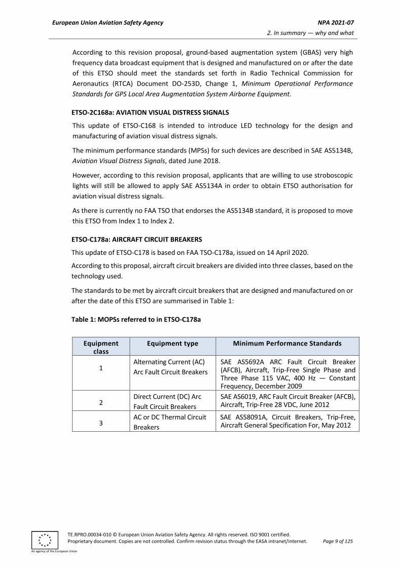
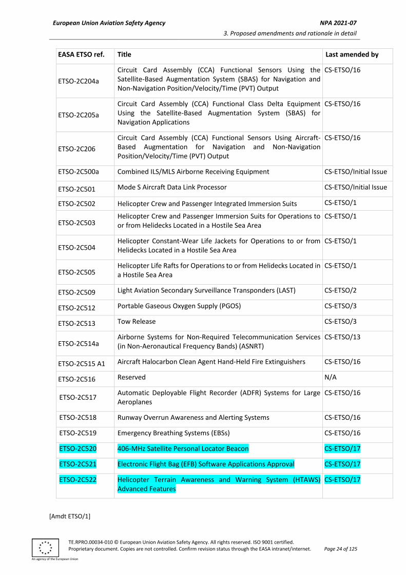
ETS0-C161ab Ground-Based Augmentation System Positioning and Navigation Equipment
CS-ETSO/717
ETSO-C162 ab Ground-Based Augmentation System Very High Frequency Data Broadcast Equipment
CS-ETSO/717
ETSO-C165b Electronic Map Systems for Graphical Depiction of Aircraft Position CS-ETSO/16
ETS0-C166b A3
Extended Squitter Automatic Dependent Surveillance-Broadcast (ADS-B) and Traffic Information Service-Broadcast (TIS-B) Equipment Operating on the Radio Frequency of 1090 Megahertz (MHz)
CS-ETSO/13
ETSO-C170 High-Frequency (HF) Radio Communication Transceiver Equipment Operating Within the Radio Frequency 1.5 to 30 Megahertz
Circuit Card Assembly (CCA) Functional Sensors Using the Satellite-Based Augmentation System (SBAS) for Navigation and Non-Navigation Position/Velocity/Time (PVT) Output
CS-ETSO/16
ETSO-2C205a
Circuit Card Assembly (CCA) Functional Class Delta Equipment Using the Satellite-Based Augmentation System (SBAS) for Navigation Applications
CS-ETSO/16
ETSO-2C206
Circuit Card Assembly (CCA) Functional Sensors Using Aircraft-Based Augmentation for Navigation and Non-Navigation Position/Velocity/Time (PVT) Output
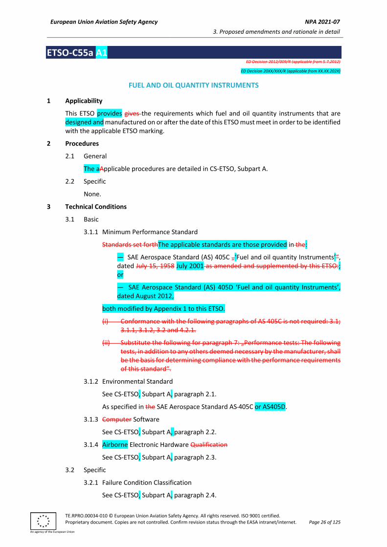
ETSO-C55a A1 ED Decision 2012/009/R (applicable from 5.7.2012)
ED Decision 20XX/XXX/R (applicable from XX.XX.202X)
FUEL AND OIL QUANTITY INSTRUMENTS
1 Applicability
This ETSO provides gives the requirements which fuel and oil quantity instruments that are designed and manufactured on or after the date of this ETSO must meet in order to be identified with the applicable ETSO marking.
2 Procedures
2.1 General
The aApplicable procedures are detailed in CS-ETSO, Subpart A.
2.2 Specific
None.
3 Technical Conditions
3.1 Basic
3.1.1 Minimum Performance Standard
Standards set forthThe applicable standards are those provided in the:
— SAE Aerospace Standard (AS) 405C „‘Fuel and oil quantity Instruments’“, dated July 15, 1958 July 2001 as amended and supplemented by this ETSO:; or
— SAE Aerospace Standard (AS) 405D ‘Fuel and oil quantity Instruments’, dated August 2012,
both modified by Appendix 1 to this ETSO.
(i) Conformance with the following paragraphs of AS 405C is not required: 3.1; 3.1.1, 3.1.2, 3.2 and 4.2.1.
(ii) Substitute the following for paragraph 7: „Performance tests: The following tests, in addition to any others deemed necessary by the manufacturer, shall be the basis for determining compliance with the performance requirements of this standard“.
3.1.2 Environmental Standard
See CS-ETSO, Subpart A, paragraph 2.1.
As specified in the SAE Aerospace Standard AS 405C or AS405D.
The failure condition classification will depend on the system on which the fuel and oil quantity instrument is installed. The classification must be determined by the safety assessment conducted as part of the installation approval. Develop eachEach fuel and oil quantity instrument shall be developed to at least the design assurance level assumed to be assigned to the system on which the fuel and oil quantity instrument is will be installed.
4 Marking
4.1 General
Marking is detailed inSee CS-ETSO, Subpart A, paragraph 1.2.
4.2 Specific
a. Mark at At least one major component must be permanently and legibly marked with all the information in SAE AS405C or AS405D, Section 3.2 (except paragraph 3.2.b). Also, mark the component must be marked with the following information:
(1) The basic type and accuracy classification, and
(2) The fluids for which the instrument is substantiated.
b. If the fuel and oil quantity instrument includes a digital computer, then the part number must include hardware and software identification. Or, you can use a separate part number for hardware and software. Either way, you must include a means to show the modification status.
NOTE: Similar software versions, approved for different software levels, must be differentiated by part number.
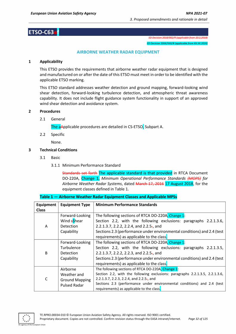
ETSO-C63ef ED Decision 2018/002/R (applicable from 20.2.2018)
ED Decision 20XX/XXX/R (applicable from XX.XX.202X)
AIRBORNE WEATHER RADAR EQUIPMENT
1 Applicability
This ETSO provides the requirements that airborne weather radar equipment that is designed and manufactured on or after the date of this ETSO must meet in order to be identified with the applicable ETSO marking.
This ETSO standard addresses weather detection and ground mapping, forward-looking wind shear detection, forward-looking turbulence detection, and atmospheric threat awareness capability. It does not include flight guidance system functionality in support of an approved wind shear detection and avoidance system.
2 Procedures
2.1 General
The aApplicable procedures are detailed in CS-ETSO, Subpart A.
2.2 Specific
None.
3 Technical Conditions
3.1 Basic
3.1.1 Minimum Performance Standard
Standards set forth The applicable standard is that provided in RTCA Document DO-220A, Change 1, Minimum Operational Performance Standards (MOPS) for Airborne Weather Radar Systems, dated March 17, 2016 17 August 2018, for the equipment classes defined in Table 1.
The following sections of RTCA DO-220A, Change 1: Section 2.2, with the following exclusions: paragraphs 2.2.1.3.6, 2.2.1.3.7, 2.2.2, 2.2.4, and 2.2.5., and Sections 2.3 (performance under environmental conditions) and 2.4 (test requirements) as applicable to the class.
B
Forward-Looking Turbulence Detection Capability
The following sections of RTCA DO-220A, Change 1: Section 2.2, with the following exclusions: paragraphs 2.2.1.3.5, 2.2.1.3.7, 2.2.2, 2.2.3, and 2.2.5., and Sections 2.3 (performance under environmental conditions) and 2.4 (test requirements) as applicable to the class.
C
Airborne Weather and Ground Mapping Pulsed Radar
The following sections of RTCA DO-220A, Change 1: Section 2.2, with the following exclusions: paragraphs 2.2.1.3.5, 2.2.1.3.6, 2.2.1.3.7, 2.2.3, 2.2.4, and 2.2.5., and Sections 2.3 (performance under environmental conditions) and 2.4 (test
The following sections of RTCA DO-220A, Change 1: Section 2.2, with the following exclusions: paragraphs 2.2.1.3.5, 2.2.1.3.6, 2.2.2, 2.2.3, and 2.2.4. Sections 2.3 (performance under environmental conditions) and 2.4 (test
Any of these classes may be implemented individually or in combination. Therefore, a piece of equipment may be eligible for one or more classes.
Functionality
This ETSO standard applies to equipment intended to:
(1) Provide airborne wind shear detection (equipment Class A). Equipment Class A provides forward-looking wind shear detection functionality. However, this ETSO does not include flight guidance system functionality in support of an approved wind shear detection and avoidance system;
(2) Provide advanced and advisory indication of potentially hazardous turbulence conditions detectable by weather radar, together with other flight information, to assist pilots with turbulence avoidance decisions (Equipment Class B);
(3) Detect and display echoes from precipitation to assist in flight crew analysis of weather. Maintain contact with geographic features such as international shoreline boundaries as a supplement to navigational orientation (Equipment Class C); and
(4) Provide timely and advisory information to pilots to enhance their situational awareness of atmospheric activity and assist with atmospheric threat avoidance decisions (Equipment Class D).
3.1.2 Environmental Standard
See CS-ETSO, Subpart A, paragraph 2.1.
3.1.3 Software
See CS-ETSO, Subpart A, paragraph 2.2.
3.1.4 Airborne Electronic Hardware
See CS-ETSO, Subpart A, paragraph 2.3.
3.2 Specific
3.2.1 Failure Condition Classification
See CS-ETSO, Subpart A, paragraph 2.4.
Failure of the function defined in paragraphs 3.1.1(2) or 3.1.1(4) resulting in unannunciated malfunction of the function is a minor failure condition.
Failure of the function defined in paragraph 3.1.1(1) or 3.1.1(3) resulting in unannunciated malfunction of the function or missed detection is a major failure condition.
Loss of the functions defined in paragraph 3.1.1 is a minor failure condition.
The applicant should provide a manual(s) containing the following items:
(1) Operating instructions and equipment limitations sufficient to describe the equipment’s operational capability;
(2) For Equipment Class B, identify the installation instructions for the identified aircraft class selected from RTCA/DO-220A, Change 1, paragraph 2.2.4.1, Table 2-4;
(3) The Eexpected radome performance for the electromagnetic signals passing through it (paragraph 2.2 of RTCA DO-213A, Minimum Operational Performance Standards for Nose-Mounted Radomes, dated 17 March 17, 2016);
(4) The Wweather performance index (range) in accordance with the requirements of RTCA DO-220A, Change 1; and
(5) The Wwind shear detection range in accordance with the requirements of RTCA DO-220A, Change 1.
4 Marking
4.1 General
Marking is detailed inSee CS-ETSO, Subpart A, paragraph 1.2.
4.2 Specific
The markings must also include the equipment class, as defined in Table 1.
ETSO-C96bc ED Decision 2018/002/R (applicable from 20.2.2018)
ED Decision 20XX/XXX/R (applicable from XX.XX.202X)
ANTICOLLISION LIGHT SYSTEMS
1 Applicability
This ETSO provides the requirements which anticollision light systems that are designed and manufactured on or after the date of this ETSO must meet in order to be identified with the applicable ETSO marking.
2 Procedures
2.1 General
The Pprocedures are detailed in CS-ETSO, Subpart A.
2.2 Specific
None.
3 Technical Conditions
3.1 Basic
3.1.1 Minimum Performance Standard
Standards set forthThe applicable standard is that provided in the Society of Automotive Engineers, Inc., (SAE) Aerospace Standard AS8017CD '‘Minimum Performance Standard for Anticollision Light Systems’', dated June 2011 August 2017, as modified by Appendix 1 to this ETSO.
3.1.2 Environmental Standard
See CS-ETSO, Subpart A, paragraph 2.1.
3.1.3 Software
See CS-ETSO, Subpart A, paragraph 2.2.
3.1.4 Airborne Electronic Hardware
See CS-ETSO, Subpart A, paragraph 2.3.
3.2 Specific
3.2.1 Failure Condition Classification
See CS-ETSO, Subpart A, paragraph 2.4.
3.2.2 Others
Note: AS8017D does not reflect the impact of updates to Certification
Specifications published after 15 August 2017, such as CS-23 Amendment 5.
4 Marking
4.1 General
Marking is detailed in See CS-ETSO, Subpart A, paragraph 1.2.
ETSO-C106a A1 ED Decision 2013/012/R (applicable from 15.7.2013)
ED Decision 20XX/XXX/R (applicable from XX.XX.202X)
AIR DATA COMPUTER
1 Applicability
This ETSO gives provides the requirements which air data computers that are designed and manufactured on or after the date of this ETSO must meet in order to be identified with the applicable ETSO marking.
2 Procedures
2.1 General
The Aapplicable procedures are detailed in CS-ETSO, Subpart A.
2.2 Specific
None.
3 Technical conditions
3.1 Basic
3.1.1 Minimum Performance Standard
The applicable standard is that provided Minimum performance standards set forth in the SAE Aerospace Standard (AS) AS8002B „‘Air Data Computer’“, dated 28 April 2020.April 1, 1985, as amended by this ETSO:
— Paragraph 4.2 of document AS 8002 shall be deleted and replaced by the following:
Static source error correction (if applicable)
Unless otherwise noted. outputs may be corrected for static source errors of the specific aircraft model in which the computer is intended to be used.
The tolerance of correction value produced from the correction profile (correction curve) residing in the computer shall be the sum of the following:
A ±15% of theoretical value of correction or equivalent of ±8.44 Pa (.0025 inch Hg) static pressure, whichever is greater.
B Value of correction curve slope times the tolerance of independent variable programming the correction curve.
When testing corrected parameters (altitude, airspeed or Mach) the nominal value of the parameter at each test point indicated in Tables 1, 3 or 4 shall be adjusted to include the correction value with tolerance limits set per A and B above.
— Exception TABLE 3, CALIBRATED AIRSPEED: A looser tolerance of ± 6.5 km/h (3.5 knots) may be used at the 148 km/h (80 knots) reference point.
ETSO-C119de ED Decision 2016/013/R (applicable from 5.8.2016)
ED Decision 20XX/XXX/R (applicable from XX.XX.202X)
AIRBORNE COLLISION AVOIDANCE SYSTEM II (ACAS II) VERSION 7.1 WITH HYBRID SURVEILLANCE
1 Applicability
This ETSO provides the requirements which Airborne Collision Avoidance System II (ACAS II) Version 7.1 equipment that are is designed and manufactured on or after the date of this ETSO must meet in order to be identified with the applicable ETSO marking.
2 Procedures
2.1 General
The Aapplicable procedures are detailed in CS-ETSO, Subpart A.
2.2 Specific
None.
3 Technical Conditions
3.1 Basic
3.1.1 Minimum Performance Standard
Standards set forth The applicable standards are those provided in EUROCAE Document ED-143, ‘Minimum Operational Performance Standards for Traffic Alert and Collision Avoidance System II (TCAS II)’, dated September 2008, Section 2 as modified by Change 1 dated April 2009, Change 2 (Version 7.1) dated April 2013, and by Appendix 1 to this ETSO and EUROCAE Document ED-221A, ‘Minimum Operational Performance Standards (MOPS) for Traffic Alert and Collision Avoidance System II (TCAS II) Hybrid Surveillance’, dated April 2013 December 2015, SSections 2 and 3, as modified by Appendix 2 to this ETSO.
3.1.2 Environmental Standard
See CS-ETSO, Subpart A, paragraph 2.1.
3.1.3 Computer Software
See CS-ETSO, Subpart A, paragraph 2.2.
3.1.4 Airborne Electronic Hardware Qualification
See CS-ETSO, Subpart A, paragraph 2.3.
3.2 Specific resulting in misleading information
None.
3.2.1 Failure Condition Classification
See CS-ETSO, Subpart A, paragraph 2.4.
Failure of the function defined in paragraph 3.1.1 of this ETSO resulting in misleading information is a hazardous failure condition.
Failure of the function defined in paragraph 3.1.1 of this ETSO resulting in a loss of function is a minor failure condition.
Appendix 1 to ETSO-C119de –— Traffic Alert and Collision Avoidance System II (TCAS II) Version 7.1 Amendment to the
EUROCAE ED-143 Change 2 Requirements
ED Decision 2016/013/R
ED Decision 20XX/XXX/R (applicable from XX.XX.202X)
This Appendix lists the EASA modifications to the MPS for Traffic Alert Aand Collision Avoidance
System (TCAS) Airborne Equipment, TCAS II Change 2, dated April 2013.
When the own ship is on the ground, clarification is required to allow the system to limit the output
of TCAS intruders to the display to those within 3 000 feet of the own altitude. In lieu of Section ‘2.2.2
System Performance’ of EUROCAE ED-143 Change 2, substitute the following:
‘2.2.2 System Performance
Note: When operating within the maximum aircraft transponder population and electromagnetic interference levels defined in subparagraph 2.2.1.2, TCAS II will provide a level of performance for active surveillance of targets-of-interest that will support the requirements for generation of collision advisory information.
Specifically, TCAS II will generate a surveillance track in range and altitude on a target-of-interest at the range and with the track probability and range accuracy specified below. This is to ensure that a correct resolution advisory can be issued in time for the pilot to maintain adequate vertical separation at closest-point-of-approach.
TCAS II will also generate, whenever possible, a surveillance track in range and altitude on a target-of-interest at the range and with the track probability and range accuracy specified below such that a correct traffic advisory can be issued as a precursor to the resolution advisory.
In addition to the surveillance requirements to support the generation of resolution and traffic advisories, TCAS II will display the range and, if available, the altitude and bearing position information on targets that generate advisories. The bearing position information will be generated according to the accuracy requirement specified below.
TCAS II will also generate for display, whenever possible, surveillance range, altitude and bearing position information on Mode C and Mode S aircraft that are within the range specified below and within ± 10 000 ft altitude relative to TCAS II when airborne, and within ± 3 000 ft altitude relative to TCAS II when on the ground.
It is acceptable to limit the output of TCAS intruders to the display to those within 3 000 ftfeet of the own altitude when the own aircraft is on the ground. This is permitted (but not required) so that the altitude surveillance volume for TCAS Mode C intruders can be consistent with the Mode S surveillance altitude limits modified in EUROCAE ED-143 Change 2 (Section 2.2.4.6.2.2.1). This allowance to limit the display to ± 3 000 ft does not modify the surveillance altitude volumes which are defined in EUROCAE ED-143, Section 2.2.4.6.
The system shall use the definition of on-ground as defined in EUROCAE ED-143, Volume II, Section 2.1.14. Alternatively, the system may use the definition of ‘operating on Ssurface’ in EUROCAE ED-221, Section 2.2.8, for on-ground.’
Appendix 2 to ETSO-C119de –— Traffic Alert and Collision Avoidance System II (TCAS II) Version 7.1 Hybrid Surveillance
Amendment to the EUROCAE ED-221 Requirements
ED Decision 2016/013/R
ED Decision 20XX/XXX/R (applicable from XX.XX.202X)
This Appendix lists the EASA modifications to MPS EUROCAE ED-221A for Traffic Alert and Collision Avoidance System II (TCAS II) Hybrid Surveillance, dated April 2013 December 2015. To facilitate the monitoring by maintenance personnel of the hybrid surveillance functionality, add
the following requirement as the fifth paragraph (including the Note) in Section 2.2.10, Monitoring
Requirements:
‘TCAS II units shall provide a means for presenting logged hybrid surveillance faults to maintenance
personnel to enable on-wing monitoring of hybrid surveillance functionality at periodic intervals.
Note: This requirement enables the implementation of a scheduled maintenance task to ensure that
hybrid surveillance is functional on aircraft without a centralised warning system and/or an on-board
maintenance computer.’
Text from EUROCAE ED-221 is provided here as needed to provide context. Text to be added is underlined. Text to be removed is lined through. 1 To ensure proper revalidation when own aircraft is operating on the surface, in the first
paragraph of EUROCAE ED-221, section 2.2.7.5 ‘Revalidation’, insert the following new underlined text:
An established track that is under hybrid surveillance (per §2.2.7.1) shall be subject to revalidation. If a track under hybrid surveillance does not satisfy the first (altitude) condition of §2.2.6.1.4, it shall be subject to revalidation every 60th surveillance update interval; if it satisfies the first and second (altitude and range) conditions of §2.2.6.1.4 but not the third (airborne) condition, it shall be subject to revalidation every 10th surveillance update interval; if it satisfies the first condition of §2.2.6.1.4 but not the second (range) condition, it shall be subject to revalidation at intervals calculated according to the following procedure. The revalidation interval t shall be calculated at the time of the initial successful validation and at the time of each successful revalidation. It shall be used as the number of surveillance update intervals until the next revalidation attempt.
1.2 Because there is a requirement specifying creation of information which is never used, in EUROCAE ED-221, section 2.2.11 ‘Interface to the CAS Logic’, delete existing lined through text from the first paragraph as follows:
Position data for tracks under passive surveillance may be provided to the CAS logic via the interface specified in Ref. A, §2.2.4.8.1. If this is done, information shall be provided in addition to that required in Ref. A, §2.2.4.8.l(a) to distinguish a position report that resulted from a passive reception of an Airborne Position Message from one that resulted from an active interrogation.
1.3 Tests 2, 3a and 3b specified in EUROCAE ED-221, section 2.4.2.5 ‘Verification of Acquisition and Maintenance of Established Tracks Using Active Surveillance’ (§2.2.6), do not need to be performed as their expected results are incorrect. Test coverage of the
input conditions associated with those tests is provided, in aggregate, by other existing tests in EUROCAE ED-221.
1.4 A new Test 11a is required in addition to the existing Test 11 specified in EUROCAE ED-221, section 2.4.2.6 ‘Verification of Maintenance of Established Tracks using Passive Surveillance’ (§2.2.7). This new test is to verify the revalidation rate when own aircraft is operating on the surface. Perform this new test in addition to the existing Test 11; the new test does not replace Test 11. Insert the following new underlined text after existing Test 11:
Test 11a (Intruder Revalidation Rate when own aircraft is operating on the surface §2.2.7.5)
This test verifies the revalidation rate when own aircraft is operating on the surface based on the altitude and range criteria for active tracking (§2.2.7.5).
(The following tests may be performed using ADS-B reports or directly decoded ADS-B messages. TIS-B and ADS-R data is not permitted.)
Scenario Description
• Intruder 1 shows that when own aircraft is operating on the airport surface and an intruder is within the altitude and range criteria for active surveillance it will be tracked using hybrid surveillance with a 10-second revalidation rate (§2.2.7.5).
• Intruder 2 shows that when own aircraft is operating on the airport surface and an intruder is within the altitude but not the range criteria for active surveillance it will be tracked using hybrid surveillance with a variable revalidation rate according to the requirements in (§2.2.7.5).
TCAS Aircraft
Altitude = 0 ft (Ground Level)
Altitude Rate = 0 FPM
Position = Sydney
Radio altitude input = 0 ft
Ground Speed is valid and at 0 knots and TCAS Air/Ground (OOGROUN) indicates on-ground.
For the tests in this section, the revalidation rate for each applicable success criteria was identified using the table in §2.2.7.5. If the implementation uses the equation method, then the revalidation interval can be longer by 10 to 20 seconds. Care should be taken to verify that the success criteria matches the value expected based on the implementation.
For each intruder:
The surveillance reports to the CAS logic are present for the duration of the track. Verify that the track is under passive surveillance.
Intruder 1
Verify that revalidation interrogations are transmitted every 10 seconds.
Intruder 2
Verify that revalidation interrogations are transmitted every 30 seconds.
The revalidation rate for each applicable success criteria was identified using the table in §2.2.7.5. If the implementation uses the equation method, then the revalidation interval can be longer by up to 10 to 20 seconds. Care should be taken to verify that the success criteria matches the value expected based on the implementation.
1.5 EUROCAE ED-221 removes a provision which allowed for larger range calculation errors above ± 60 degrees latitude from RTCA/DO-300, Section 2.2.7.6 (from which ED-221 is derived), but the associated tests were not updated accordingly. To account for the removal of that provision, delete the following lined through text from EUROCAE ED-221, sections 2.4.2.8 ‘Verification of Error Budget in Computing Slant Range from Passive Data’ and 2.4.2.10 ‘Verification of DF17 Decoding’, and insert as underlined below a clarifying note in Appendix A ‘Conversion of Reported Positions to Slant Range’, section A.1 ‘Overview’.
2.4.2.8 Verification of Error Budget in Computing Slant Range from Passive Data
(…)
If the test method is used to demonstrate compliance with the requirement, then this paragraph describes one potential scenario. Own aircraft and intruder aircraft are travelling towards each other at 600 kt at high latitude (near 60 degrees). If the error between the passive range estimate and active range measurement is less than 145 meters then the intent of the requirement is met. The error in range computation of tests at slower closure rates can be used to extrapolate or predict errors at the 1 200 kt closure rate.
For all of the Intruders with Latitudes within ±60 degrees, verify that the range for each intruder is within 145 m of the calculated range identified in Table 3.
For all of the Intruders with Latitudes within ±60 degrees, verify that the bearing for each intruder is within 3 degrees of the calculated bearing identified in Table 3.
Verify that the error in range from the calculated range does not use more of the error budget allowed for range based on the completion of Test §2.4.2.8 (Verification of Error Budget in Computing Slant Range from Passive Data) Test 1.
(…)
A.1 OVERVIEW
This Appendix provides useful guidance on computing range from own and reported position data. This Appendix does not recommend a particular implementation and should be used for reference only.
Firstly, the exact conversion equations from position to slant range are given. The computational requirements for the exact conversion equations are reasonable and could be used as is for modern processors and typical TCAS traffic loads.
Secondly, several approximate conversion equations from position to slant range are presented. For circumstances where hybrid surveillance is implemented as a software upgrade to existing processors, it may be desirable to use approximations to the conversion equations to reduce the computational requirements. The errors in the approximate equations are presented and compared to the computational accuracy requirements of §2.2.7.6, which requires a maximum 145 m processing error when calculating slant range.
Note: The equations in A.2 provide an example of conversion equations which meet the accuracy requirements. The approximation equations provided in the Appendix may not provide the required accuracy.
ETSO-C127bc ED Decision 2016/013/R (applicable from 5.8.2016)
ED Decision 20XX/XXX/R (applicable from XX.XX.202X)
ROTORCRAFT, TRANSPORT AEROPLANE, AND SMALL AEROPLANE SEATING SYSTEMS
1 Applicability
This ETSO provides the Minimum Performance Standards (MPSs) that rotorcraft, large (transport) aeroplane, and small aeroplane seating systems of the following designated types that are designed and manufactured on or after the date of this ETSO must meet in order to be identified with the applicable ETSO marking.
This ETSO’s standardsThe standards of this ETSO apply to equipment intended to be utilised as aircraft seating systems of the following classifications:
(1) Seat Type and applicable Aircraft Category:
(a) Type A AirplaneAeroplane. Aircraft Category: Transport
(b) Type B Rotorcraft. Aircraft Category: Large (Transport) or Small (Normal)
(c) Type C Small AirplaneAeroplane. Aircraft Category:
(CS-23 up to Amendment 4) Normal, Utility, Acrobatic, or Commuter;
(CS-23 Amendment 5 and subsequent amendments) Normal Level 1, Normal Level 2, Normal Level 3, Normal Level 4.
(2) Seat Subtype:
(a) Subtype 1 Passenger
(b) Subtype 2 Flight Attendant
(c) Subtype 3 Observer
(d) Subtype 4 Pilot/Co-pilot
(3) Seat Orientation:
(a) Forward-Facing
(b) Rearward-Facing
Note: Seats with installation limitations of angles more than 18 degrees from the aircraft centre line are not addressed by this standard. See Appendix 1 to this ETSO amending SAE AS8049B, subsection 5.3.3.5.i.
(a) Forward facing — Installation of forward-facing seating systems in the aircraft at up
to an angle of 18° relative to the aircraft longitudinal axis.
(b) Rearward facing — Installation of rearward-facing seating systems in the aircraft at
up to an angle of 18° relative to the aircraft longitudinal axis.
(c) Side facing — Installation of side-facing seating systems in the aircraft at between
80° and 100° relative to the aircraft longitudinal axis.
(d) Oblique facing — Installation of forward-facing seating systems in the aircraft, at
greater than 18° and no greater than 45° relative to the aircraft longitudinal axis.
The Aapplicable procedures are detailed in CS-ETSO, Subpart A.
2.2 Specific
None.
3 Technical Conditions
3.1 General Basic
The standards of this ETSO apply to equipment intended to be utilised as aircraft seating
systems.
3.1.1 Minimum Performance Standard
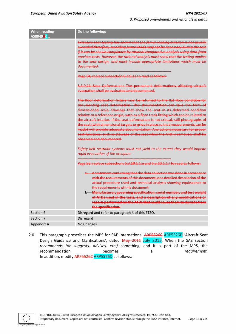
New models of rotorcraft, large (transport) aeroplane airplane, and small aeroplane airplane seating systems identified and manufactured on or after the effective date of this ETSO must meet the requirements in the following standards: SAE International’s Aerospace Standard (AS) 8049B, Performance Standard for Seats in Civil Rotorcraft, Transport Aircraft, and General Aviation Aircraft, dated January 2005, as modified by Appendix 1 to this ETSO; SAE Aerospace Recommended Practice (ARP) 5526C, Aircraft Seat Design Guidance and Clarifications, dated May 2011, as modified by Appendix 1 to this ETSO; and Appendix 2 to this ETSO (for specific elective requirements).
— SAE AS8049C, ‘Performance Standard for Seats in Civil Rotorcraft, Transport
Aircraft, and General Aviation Aircraft’, dated August 2015, as modified by
Appendix 1 to this ETSO;
— SAE AS8049/1B, ‘Performance Standards for Side-Facing Seats in Civil
Rotorcraft, Transport Aircraft, and General Aviation Aircraft’, dated
December 2016, as modified by Appendix 1 to this ETSO;
— SAE ARP5526D, ‘Aircraft Seat Design Guidance and Clarifications’, dated July
2015, as modified by Appendix 1 of this ETSO;
— SAE AS6316, ‘Performance Standards for Oblique Facing Passenger Seats in
Transport Aircraft’, dated June 2017, as modified by Appendix 1 to this ETSO;
— SAE ARP6337, ‘Design, Manufacturing, and Performance Standard for
Composite Materials Used on Aircraft Seat Structures’, dated November
2020, as modified by Appendix 1 of this ETSO, and by Appendix 2 to this ETSO
for specific elective requirements.
3.1.1.1 Functional Qualification
Demonstrate the required functional performance under the test conditions
specified in:
— SAE AS8049C, ‘Performance Standard for Seats in Civil Rotorcraft, Transport
Aircraft, and General Aviation Aircraft’, dated August 2015, as amended by
Appendix 1 of this ETSO for forward- and aft-facing seats;
— SAE AS8049/1B, ‘Performance Standards for Side-Facing Seats in Civil
Rotorcraft, Transport Aircraft, and General Aviation Aircraft’, dated
December 2016, as modified by Appendix 1 to this ETSO for side-facing seats;
— SAE AS6316, ‘Performance Standards for Oblique Facing Passenger Seats in
Transport Aircraft’, dated June 2017, as modified by Appendix 1 to this ETSO
for oblique-facing seats;
— SAE ARP5526D, ‘Aircraft Seat Design Guidance and Clarifications’, dated July
2015, as amended by Appendix 1 to this ETSO;
— SAE ARP6337, ‘Design, Manufacturing, and Performance Standard for
Composite Materials Used on Aircraft Seat Structures’, dated November
2020, as modified by Appendix 1 to this ETSO; and
— Appendix 2 of this ETSO for specific elective requirements.
3.1.2 Environmental Standard
None Not applicable.
3.1.3 Computer Software
None Not applicable.
3.1.4 Airborne Electronic Hardware
Not applicable.
3.2 Specific
None.
3.2.1 Failure Condition Classification
There is no standard minimum failure condition classification for this ETSO. The
failure condition classification appropriate for the article will depend on the
intended use of the article in a specific aircraft. The loss of function and the
malfunction failure condition classifications for which the equipment is designed
should be documented.
4 Marking
4.1 General
Marking is detailed in CS-ETSO, Subpart A, paragraph 1.2. In addition, each seating system shall be legibly and permanently marked with the following:
The permanent and legible marking of at least one major component is required, with all
the information as detailed in CS-ETSO, Subpart A, paragraph 1.2.
4.2 Specific
The markings must also include the serial number and the following:
(i) (1) The specific seat MPS complied with as abbreviated by paragraphs 4.2(1)(a)4.2.(1).(a) through to 4.2(1)(e)4.2.(1).(e) below. Separate each applicable identifier with a dash.
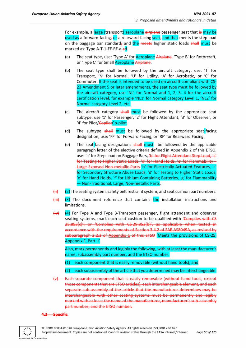
For example, a large (transport) aeroplane airplane passenger seat that is may be used as a forward-facing, or a rearward-facing seat, and that meets the step load on the baggage bar standard, and the meets higher static loads shall must be marked as: Type A-T-1-FF-RF-a-cd.
(a) The seat type, use: ‘Type A’ for Aeroplane Airplane, ‘Type B’ for Rotorcraft, or ‘Type C’ for Small Aeroplane Airplane.
(b) The seat type shall be followed by the aircraft category, use: ‘T’ for Transport, ‘N’ for Normal, ‘U’ for Utility, ‘A’ for Acrobatic, or ‘C’ for Commuter. If the seat is intended to be used on aircraft compliant with CS-23 Amendment 5 or later amendments, the seat type must be followed by the aircraft category, use ‘NL’ for Normal and 1, 2, 3, 4 for the aircraft certification level, for example ‘NL1’ for Normal category Level 1, ‘NL2’ for Normal category Level 2, etc.
(c) The aircraft category shall must be followed by the appropriate seat subtype: use ‘1’ for Passenger, ‘2’ for Flight Attendant, ‘3’ for Observer, or ‘4’ for Pilot/CopilotCo-pilot.
(d) The subtype shall must be followed by the appropriate seat-facing designation, use: ‘FF’ for Forward Facing, or ‘RF’ for Rearward Facing.
(e) The seat-facing designations shall must be followed by the applicable paragraph letter of the elective criteria defined in Appendix 2 of this ETSO, use: ‘a’ for Step Load on Baggage Bars, 'b’ for Flight Attendant Step Load, ‘c’ for Testing to Higher Static Loads, ‘d’ for Hand Holds, ‘e’ for Flammability –Large Exposed Non-metallic Parts ‘b’ for Electrically Actuated Features, ‘c’ for Secondary Structure Abuse Loads, ‘d’ for Testing to Higher Static Loads, ‘e’ for Hand Holds, ‘f’ for Lithium Containing Batteries, ‘g’ for Flammability — Non-Traditional, Large, Non-metallic Parts.
(ii) (2) The seating system, safety belt restraint system, and seat cushion part numbers.
(iii) (3) The document reference that contains the installation instructions and limitations.
(iv) (4) For Type A and Type B-Transport passenger, flight attendant and observer seating systems, mark each seat cushion to be qualified with ‘Complies with CS 25.853(c)’, or ‘Complies with CS 29.853(b)’, as applicable when tested in accordance with the requirements of Section 3.4.2 of SAE AS8049A, as revised by subparagraph 2.2.3 of Appendix 1 of this ETSO ‘Meets the provisions of CS-25, Appendix F, Part II’.
Also, mark permanently and legibly the following, with at least the manufacturer’s name, subassembly part number, and the ETSO number:
(1) each component that is easily removable (without hand tools); and
(2) each subassembly of the article that you determined may be interchangeable.
(v) Each separate component that is easily removable (without hand tools, except those components that are ETSO articles), each interchangeable element, and each separate sub-assembly of the article that the manufacturer determines may be interchangeable with other seating systems must be permanently and legibly marked with at least the name of the manufacturer, manufacturer’s sub-assembly part number, and the ETSO number.
Appendix 1 to ETSO-C127bc –— MPS For Rotorcraft, Transport Aeroplane, and Small Aeroplane Seating Systems
ED Decision 2016/013/R
ED Decision 20XX/XXX/R (applicable from XX.XX.202X)
1.0. Forward- and aft-facing seating systems must meet the requirements of Table 1 of this
Appendix. This Appendix prescribes the EASA modifications to the MPS for SAE International’s Aerospace Standard (AS) 8049B 8049C, ‘Performance Standard for Seats in Civil Rotorcraft, Transport Aircraft, and General Aviation Aircraft’, dated January 2005 August 2015. When the SAE section recommends (or suggests, advises, etc.) something, and it is part of the MPS, the recommendation becomes a requirement. In addition, modify AS8049B8049C as follows:
Table 1 — SAE AS8049B8049C
When reading AS8049BC…
Do the following:
Section 1 Disregard
Section 2 Disregard
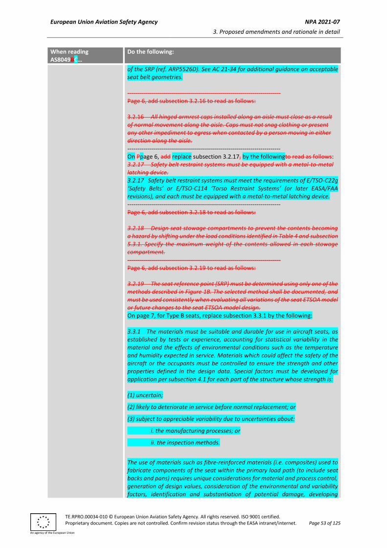
Section 3 Apply all suball the subsections unless disregarded or modified below as shown below: ----------------------------------------------------------------------------- Page 5, disregard subsection 3.1. ----------------------------------------------------------------------------- Page 6, replace subsection 3.2.7 to read as follows: 3.2.7 When an under-seat baggage restraint is incorporated in a passenger seat, it shall be designed to restrain at least 9.1 kg (20 lb) or its placarded weight of stowed items per passenger place under the dynamic and static (forward and sideward directions only) test conditions of this document in a manner that will not significantly impede rapid egress from the seat. ----------------------------------------------------------------------------- On Ppage 6, replace subsection 3.2.15 by the following to read as follows: 3.2.15 Except for rearward facing seats and seats equipped with multiple anchorage point pelvic restraints (e.g. Y-belts), the pelvic restraint system shall be designed such that the vertical angle between the pelvic restraint centerline and the seat reference point (SRP) waterline shall range from 35° to 55°. The SRP water line is a line/plane passing through the SRP parallel to the floor waterline. The pelvic restraint centerline is formed by a line from the pelvic restraint anchorage to a point located 250 mm (9.75 in) forward of the SRP and 180 mm (7.0 in) above the SRP water line. In addition, the pelvic restraint anchorage point(s) must be located no further than 2.0 inches forward of the SRP (ref Figure 1A). See the FAA AC 21-34 for additional guidance for acceptable seat belt geometry. 3.2.1 Except for rearward-facing seats and seats equipped with multiple anchorage point pelvic restraints (e.g. Y-belts), the pelvic restraint system must be designed such that the vertical angle between the pelvic restraint centre line and the seat reference point (SRP) waterline must range from 35° to 55°. The SRP waterline is a line/plane passing through the SRP parallel to the floor waterline. The pelvic restraint centre line is formed by a line from the pelvic restraint anchorage to a point located 9.75 inches (250 mm) forward of the SRP and 7.0 inches (180 mm) above the SRP waterline. In addition, the pelvic restraint anchorage point(s) must be located no further than 2.0 inches (51 mm) forward
of the SRP (ref. ARP5526D). See AC 21-34 for additional guidance on acceptable seat belt geometries. ----------------------------------------------------------------------------- Page 6, add subsection 3.2.16 to read as follows: 3.2.16 All hinged armrest caps installed along an aisle must close as a result of normal movement along the aisle. Caps must not snag clothing or present any other impediment to egress when contacted by a person moving in either direction along the aisle. ----------------------------------------------------------------------------- On Ppage 6, add replace subsection 3.2.17, by the followingto read as follows: 3.2.17 Safety belt restraint systems must be equipped with a metal-to-metal latching device. 3.2.17 Safety belt restraint systems must meet the requirements of E/TSO-C22g ‘Safety Belts’ or E/TSO-C114 ‘Torso Restraint Systems’ (or later EASA/FAA revisions), and each must be equipped with a metal-to-metal latching device. ----------------------------------------------------------------------------- Page 6, add subsection 3.2.18 to read as follows: 3.2.18 Design seat stowage compartments to prevent the contents becoming a hazard by shifting under the load conditions identified in Table 4 and subsection 5.3.1. Specify the maximum weight of the contents allowed in each stowage compartment. ----------------------------------------------------------------------------- Page 6, add subsection 3.2.19 to read as follows: 3.2.19 The seat reference point (SRP) must be determined using only one of the methods described in Figure 1B. The selected method shall be documented, and must be used consistently when evaluating all variations of the seat ETSOA model or future changes to the seat ETSOA model design. On page 7, for Type B seats, replace subsection 3.3.1 by the following: 3.3.1 The materials must be suitable and durable for use in aircraft seats, as established by tests or experience, accounting for statistical variability in the material and the effects of environmental conditions such as the temperature and humidity expected in service. Materials which could affect the safety of the aircraft or the occupants must be controlled to ensure the strength and other properties defined in the design data. Special factors must be developed for application per subsection 4.1 for each part of the structure whose strength is: (1) uncertain;
(2) likely to deteriorate in service before normal replacement; or
(3) subject to appreciable variability due to uncertainties about:
i. the manufacturing processes; or
ii. the inspection methods.
The use of materials such as fibre-reinforced materials (i.e. composites) used to fabricate components of the seat within the primary load path (to include seat backs and pans) requires unique considerations for material and process control, generation of design values, consideration of the environmental and variability factors, identification and substantiation of potential damage, developing
criteria to assess the post-impact structural integrity, and creating instructions for continued airworthiness (ICAs). Applicants may follow the relevant guidance in AC 20-107B when addressing these concerns. Test plans to develop design allowable data and special factors or alternative justification for the use of service history must be approved in advance by EASA. Note: An ETSO approval does not include installation approval in an aircraft, and special conditions may be required to gain installation approval if the design includes new and novel materials and processes (e.g. composite materials, bonded joints, or additive manufacturing) in the primary load path. Applicants for seat installations under CS-27 and CS-29 should ensure that all the composite seat components comply with the relevant regulatory requirements for material and process control, and that the manufacturing and service instructions are adequate to ensure that the seat complies with the crashworthiness requirements throughout its life.
On page 7, for Type A-T, Type C seats (all the aircraft categories detailed in 1(1)c of this ETSO), replace subsection 3.3.1 by Table 5 of Appendix 1 of this ETSO. Note: An ETSO approval does not include installation approval in an aircraft, and special conditions may be required to gain installation approval if the design includes new and novel materials and processes (e.g. composite materials, bonded joints, or additive manufacturing) in the primary load path. Applicants for seat installations under CS-23 and CS-25 should ensure that all the composite seat components comply with the relevant regulatory requirements for material and process control, and that the manufacturing and service instructions are adequate to ensure that the seat complies with the crashworthiness requirements throughout its life.
On page 7, replace subsection 3.3.2 by the following: 3.3.2 The methods and processes used for fabrication and assembly must produce consistently sound seats. If a fabrication process requires close control to reach this objective, the process must be performed in accordance with the design data (e.g. process specification).
On page 7, add subsection 3.3.4 as follows: 3.3.4 Each part of the seat structure must be protected against deterioration or loss of strength in service due to any cause (such as corrosion, wear, impact damage, environmental degradation, etc.) and have provisions for ventilation and drainage where necessary for protection.
3.4.1 All the materials used on seats must meet the requirements of subsection 3.4.1.1, 3.4.1.2, 3.4.1.3, or 3.4.1.4. The definition and use of parts that are considered small parts that would not contribute significantly to the propagation of a fire must be approved in advance by EASA. When inflatable materials are used (i.e. material used in the fabrication of inflatable restraints, airbags, etc.), the inflatable material must meet the flammability requirements of CS-25, Appendix F, Part I (a)(iv). Note: Inflatable materials used in devices to increase occupant safety are a novel or unusual design feature that may be subject to special conditions and additional certification requirements for installation approval. The fire protection properties of the material may be demonstrated by following FAA Policy Statement PS- ANM-25.853-01 R2, ‘Flammability Testing of Interior Materials’ (dated 3 July 2013) or tested in accordance with the applicable chapter of the Aircraft Materials Fire Test Handbook — DOT/FAA/AR-00/12. --------------------------------------------------------------------------------------------------------- Add subsections 3.4.1.1, 3.4.1.2, 3.4.1.3, and 3.4.1.4 as follows: 3.4.1.1 All the materials used on Type A-T and Type B-T seats must be tested in accordance with the procedures, and meet the fire protection requirements, of CS-25, Appendix F, Part I, except where the material properties, size and quantity would not create or propagate a cabin fire. The fire protection properties of the material may also be demonstrated by following FAA Policy Statement PS-ANM-25.853-01 R2, ‘Flammability Testing of Interior Materials’ (dated 3 July 2013) or tested in accordance with the Aircraft Materials Fire Test Handbook — DOT/FAA/AR-00/12, Chapter 1 or 3. 3.4.1.2 All the materials used on Type B-N, Type C-N, Type C-NL1, Type C-NL2, Type C-NL3, Type C-U, and Type C-A seats must have flame-resistant properties. The materials must be tested to and must meet the requirements of paragraph 8.b of FAA Advisory Circular (AC) 23-2A Change 1, ‘Flammability Tests’ (dated 15 February 2013). 3.4.1.3 All the materials used on Type C-C seats must be tested in accordance with the test procedures of CS-23, Appendix F, Part I (Amendment 5) or the Aircraft Materials Fire Test Handbook — DOT/FAA/AR-00/12, Chapter 1 or 3, and must meet the following flammability performance requirements: 3.4.1.3.1 The panels, walls, structural flooring, and materials used in the construction of stowage compartments (other than underseat stowage compartments and compartments for stowing small items such as magazines and maps) must be self-extinguishing. The average burn length may not exceed 6 inches and the average flame time after removal of the flame source may not exceed 15 seconds. Drippings from the test specimen may not continue to flame for more than an average of 3 seconds after falling. 3.4.1.3.2 Floor coverings, textiles (including draperies and upholstery), seat cushions, padding, decorative and non-decorative coated fabrics, leather, electrical conduits, transparencies, moulded and thermoformed parts, and trim strips (decorative and chafing) that are constructed of materials not covered in subsection 3.4.1.3.3 must be self-extinguishing. The average burn length may not exceed 8 inches and the average flame time after removal of the flame source
may not exceed 15 seconds. Drippings from the test specimen may not continue to flame for more than an average of 5 seconds after falling. 3.4.1.3.3 Acrylic windows and signs, parts constructed in whole or in part of elastomeric materials, seatbelts, and shoulder harnesses may not have an average burn rate greater than 2.5 inches per minute. 3.4.1.3.4 Except for electrical wire cable insulation, and for small parts where the material properties, size, and quantity would not create or propagate a cabin fire, the materials in items not specified in subsections 3.4.1.3.1 through 3.4.1.3.3 may not have a burn rate greater than 4.0 inches per minute. 3.4.1.4 All the materials used on Type C-NL4 seats must be self-extinguishing and tested in accordance with the test procedures of CS-23, Appendix F (Amendment 4), or the Aircraft Materials Fire Test Handbook — DOT/FAA/AR-00/12, Chapter 1.
On page 8, replace subsection 3.4.2 by the following: Cushion systems on Type A-T and Type B-T passenger, flight attendant and observer seats must meet the fire protection requirements of CS-25, Appendix F, Part II. The fire protection properties of the material may also be demonstrated by following FAA AC 25.853-1, ‘Flammability Requirements for Aircraft Seat Cushions’ (dated 17 September 1986), tested in accordance with the Aircraft Materials Fire Test Handbook — DOT/FAA/AR-00/12, Chapter 7 and, where applicable, FAA Policy Statement ANM-115-07-002, ‘Policy Statement on Certification for Flammability of Lightweight Seat Cushions’ (dated 16 April 2009).
On page 8, replace subsection 3.4.3 by the following: The insulation on electrical wires and cables on all Type A, Type B and Type C seats must meet the fire protection requirements of CS-25, Appendix F, Part I, (a)(3), or the Aircraft Materials Fire Test Handbook — DOT/FAA/AR-00/12, Chapter 4. Page 10, replace subsection 3.4.1 to read as follows: 3.4.1 Test the materials in Type A Transport and Type B Transport seating systems, ensuring they meet the fire protection properties specified in CS-25, Appendix F, Part I, paragraph (a)(1). The material’s fire protection properties may be demonstrated using the methods provided in the FAA policy statement, PS-ANM-25.853-01-R2, Flammability Testing of Interior Materials, which may permit substantiation based on previously tested materials. The definition and use of parts that are considered small parts that would not contribute significantly to the propagation of a fire must be approved in advance by EASA. When inflatable restraints are included, the airbag material shall meet the flammability requirements of CS-25, Appendix F, Part I(a)(iv). Note: Inflatable restraints are a new and novel technology that may be subject to significant additional special conditions and certification requirements for installation approval.
Materials in Normal, Utility and Acrobatic category Type C seating systems must have flame-resistant properties as defined in 14 CFR Part 1. Test the materials to meet the requirements of paragraph 8.b of the FAA Advisory Circular (AC) 23-2A, Change 1, Flammability Tests. Commuter category Type C seating systems shall meet the flammability performance requirements defined in CS 23.853(d)(3), and tested as prescribed in CS-23, Appendix F, Part I. Materials in Type B Normal Rotorcraft seating systems must have flame-resistant properties as defined in 14 CFR Part 1. Test the materials to meet the requirements of paragraph 8.b of the FAA Advisory Circular 23-2A ‘Flammability Test’, dated May 11, 2007. The material’s fire protection properties may also be demonstrated by analysis (similarity) to provide equivalent protection. Type A — Transport airplane insulation on electrical wire and electrical cable, and materials used to provide additional protection for the wire and cable, must be self-extinguishing when tested in accordance with the applicable portions of Appendix F, Part I of CS-25. Type B — Rotorcraft insulation on electrical wire and cable must be self-extinguishing when tested in accordance with Appendix F, Part I(a)(3), to CS-25. Type C seats with insulation on electrical wire and electrical cable must be self-extinguishing when tested at an angle of 60 degrees in accordance with the applicable portions of Appendix F to CS-23. The average burn length must not exceed 3 inches (76 mm) and the average flame time after removal of the flame source must not exceed 30 seconds. Drippings from the test specimen must not continue to flame for more than an average of 3 seconds after falling. ----------------------------------------------------------------------------- Page 10, replace subsection 3.4.2 to read as follows: Type A Transport and Type B Transport — passenger, flight attendant, and observer seat cushion systems shall be tested to and shall meet the fire protection provisions of CS-25 Appendix F, Part II. The material’s fire protection may also be demonstrated by following the FAA AC 25.853-1 ‘Flammability Requirements for Aircraft Seat Cushions’ and, where applicable, the FAA Policy Statement ANM-115-07-002 on certification for flammability of lightweight seat cushions. ----------------------------------------------------------------------------- Page 12, replace subsection 3.5.7 to read as follows: 3.5.7 Deployable Items: Certain items on the seat, such as food trays, leg rests, arm caps over in-arm tray tables, etc., are used by passengers in flight and are required to be stowed for taxi, takeoff and landing. Deployment of such items should be treated as ‘permanent deformation’ if the item deploys into an area that must be used by multiple passengers (in addition to the occupant of the seat) for egress. The location of the measuring point used for determining the deformation of the deployed item shall be either at the point of full deployment or at the point of the actual deployment if a partially deployed item resists further deployment upon application of a static load of 45 N (10 lb) along the direction of the inertial load path. Such deployments can be considered acceptable, even if they exceed the provisions of 3.5 and its subparagraphs, if they are readily pushed out of the way by normal passenger movement, and remain in a position that does not affect egress (i.e., when pushed out of the way
it remains in that position). Normal passenger movement is the act of the seated occupant getting up out of the seat and moving to egress the airplane (i.e., unbuckling their restraint, standing, turning towards the aisle and moving into the aisle). It does not include additional movements to lift or stow items, or latching an item in place. Any items that remain in a position that would affect egress shall be reported as permanent deformation. If the food tray table deploys as a result of being struck by the ATD head during a row-to-row HIC test and the food tray table is easily pushed out of the way, the deployment is acceptable and does not need to be considered as permanent deformation (except for seats installed where deployment may affect egress through a required exit path — see below). It is not required for the food tray table to remain in a position that does not affect egress. ‘Easily pushed out of the way’ is not required to be by normal passenger movement. Determination of the food tray deploying as a result of being struck by the ATD head during the test shall be made by evaluation of the high-speed film/video. If the food tray table deploys as a result of being struck by the ATD head during the test and the food tray table is not easily pushed out of the way, the deployment shall be treated as permanent deformation. Any food tray deployment on a seat that will be installed where deployment may affect egress through a required exit path, regardless of being struck by the ATD head, shall be treated as permanent deformation.
Section 4 Apply all sub all the subsections unless disregarded or modified as shown below: --------------------------------------------------------------------------------------------------------- On page 14, revise column 5 in Table 4A as follows:
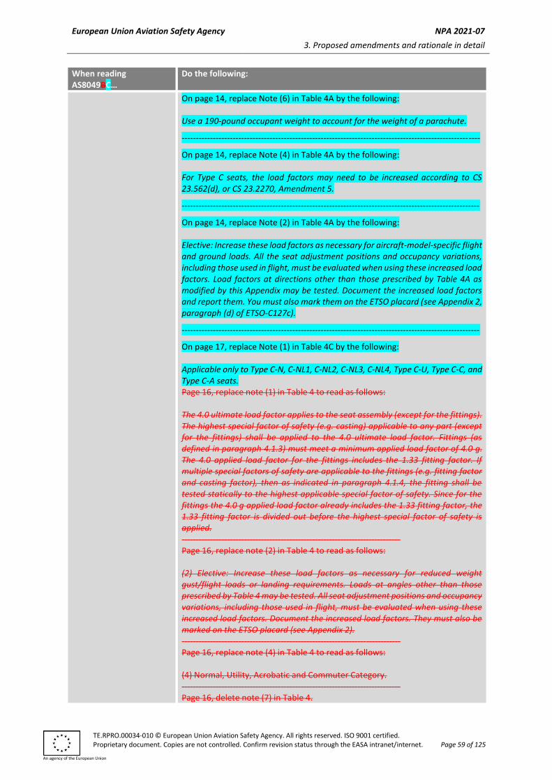
On page 14, replace Note (4) in Table 4A by the following: For Type C seats, the load factors may need to be increased according to CS 23.562(d), or CS 23.2270, Amendment 5.
On page 14, replace Note (2) in Table 4A by the following: Elective: Increase these load factors as necessary for aircraft-model-specific flight and ground loads. All the seat adjustment positions and occupancy variations, including those used in flight, must be evaluated when using these increased load factors. Load factors at directions other than those prescribed by Table 4A as modified by this Appendix may be tested. Document the increased load factors and report them. You must also mark them on the ETSO placard (see Appendix 2, paragraph (d) of ETSO-C127c).
On page 17, replace Note (1) in Table 4C by the following: Applicable only to Type C-N, C-NL1, C-NL2, C-NL3, C-NL4, Type C-U, Type C-C, and Type C-A seats. Page 16, replace note (1) in Table 4 to read as follows: The 4.0 ultimate load factor applies to the seat assembly (except for the fittings). The highest special factor of safety (e.g. casting) applicable to any part (except for the fittings) shall be applied to the 4.0 ultimate load factor. Fittings (as defined in paragraph 4.1.3) must meet a minimum applied load factor of 4.0 g. The 4.0 applied load factor for the fittings includes the 1.33 fitting factor. If multiple special factors of safety are applicable to the fittings (e.g. fitting factor and casting factor), then as indicated in paragraph 4.1.4, the fitting shall be tested statically to the highest applicable special factor of safety. Since for the fittings the 4.0 g applied load factor already includes the 1.33 fitting factor, the 1.33 fitting factor is divided out before the highest special factor of safety is applied. ----------------------------------------------------------------------------- Page 16, replace note (2) in Table 4 to read as follows: (2) Elective: Increase these load factors as necessary for reduced weight gust/flight loads or landing requirements. Loads at angles other than those prescribed by Table 4 may be tested. All seat adjustment positions and occupancy variations, including those used in flight, must be evaluated when using these increased load factors. Document the increased load factors. They must also be marked on the ETSO placard (see Appendix 2). ----------------------------------------------------------------------------- Page 16, replace note (4) in Table 4 to read as follows: (4) Normal, Utility, Acrobatic and Commuter Category. ----------------------------------------------------------------------------- Page 16, delete note (7) in Table 4.
Explanation: The seating system’s manufacturer doesn’t control the CS-23 requirements applying to the seat installation. The manufacturer may test to load factors higher than required in Table 4 under the provisions of Appendix 2, paragraph c, to this ETSO. ----------------------------------------------------------------------------- Page 16, add a reference of note (8) to be applicable to the Upward load direction for Type C Seat in Table 4. Add note (8) to Table 4 to read as follows: (8) Use a factor of 4.5 for Acrobatic Category seats.
Section 5 Apply all sub all the subsections unless disregarded or modified as shown below: --------------------------------------------------------------------------------------------------------- On page 18, replace Section 5.0 by the following: The initial qualification of a seat shall be performed by static and dynamic tests. Computer modelling analytical techniques may be used as established by AC 20-146, Revision A, paragraph 2.5. The use of computer modelling analytical techniques must be established by the applicant and accepted by EASA.
On page 22, replace subsection 5.1.9 by the following: The load due to any item of mass, including the seat that is not restrained by the occupant restraint system, must be applied in a representative manner at the CG of the mass, or with a corrective factor applied in a conservative manner relative to the CG of the item of mass. Note: If the retention of an item of mass attached to the seat is demonstrated by the dynamic qualification tests of subsection 5.3, no further demonstration of retention for the forward and downward static conditions is required; however, a demonstration of retention of items of mass for the side, up, and aft static conditions is still required.
On page 24, replace subsection 5.3 by the following: 5.3 Dynamic Qualification Tests
This section specifies the dynamic tests to satisfy the requirements of this document.
For Type A seats: You may demonstrate compliance with the dynamic test procedures and documentation of subsection 5.3.1 ‘Dynamic Impact Test Parameters’ to subsection 5.3.9.2 ‘Impact Pulse Shape’ of SAE AS8049C by the equivalent procedures of FAA AC 25.562-1B, Change 1. The equivalent method must be included in the document that contains the installation instructions and limitations, and must be used consistently when evaluating all the variations of the seat and any subsequent changes to the seat design.
For Type A seats: You can also use the simplified procedures for head injury criteria (HIC) outlined in AC 25.562-1B, Change 1, instead of the test conditions in AS8049C subsection 5.3.6.2.
Except for Hybrid III ATDs (49 CFR Part 572, Subpart E) modified in accordance with SAE Technical Paper 1999-01-1609, the use of an equivalent ATD must be established by the applicant and accepted by EASA.
Add subsection 5.3.1.5 as follows: 5.3.1.5 Sensor-driven restraint systems If a sensor-driven restraint system (e.g. an airbag, inflatable restraint, seatbelt pre-tensioner, deployable panel) is used as part of the seating system, additional threshold testing must be conducted to ensure that the structural and occupant injury criteria continue to be met when the sensor-driven restraint system does not activate. The threshold test must test the seating system at an inertial load no less than the maximum dynamic impact acceleration allowed by the sensor-driven restraint system without activating. For seats with sensor-driven restraint systems, it must be shown that the system will activate and provide protection under emergency landing conditions where it is necessary to prevent serious injury to the occupants. The system must provide a consistent approach to injury protection throughout the range of occupants (2-year-old child to 95th percentile male) whether it is designed to manage injury parameters (e.g. HIC, Nij, neck rotation, etc.) or occupant motion. The system must be included in each test. If sensor-driven restraint systems influence the test results, they must be active during the test. Seats that require a sensor-driven restraint system to meet the requirements of this ETSO must include the detailed design definition of the system and any other information required for installation as part of the document that contains the installation instructions and limitations. Sensor-driven restraint systems may be used to control occupant motion. The intended function of the system must be demonstrated during each applicable test.
On page 39, replace subsection 5.3.4.1(a) by the following: (a) Sled or drop tower vehicle acceleration data measurements must be in accordance with the Channel Class 60 requirements.
On page 42, replace subsection 5.3.6.3 by the following: 5.3.6.3 If a non-symmetrical upper torso restraint system (such as a single diagonal shoulder belt) is used in a system, it must be installed in the test fixture in a position representative of that in the aircraft.
For a forward-facing seat equipped with a single diagonal shoulder belt, the Test 2 yaw direction must be selected to address the direction which would increase the likelihood of the occupant not being restrained (typically over the trailing shoulder) and assessment of the maximum upper torso restraint load, which requires testing in the critical structural direction. In some cases, this may require testing in both directions of yaw.
For a Type A seat, testing per AC-25.562-1B, Change 1, paragraph 3.b(3), may be used.
On page 44, replace subsection 5.3.8.3(a) by the following: (a) Prior to seating the ATD, all the seat adjustments and controls must be set as indicated in 5.3.6.4. To the extent that they influence the injury criteria, all the seat adjustments and controls should be in the design position intended for a 50th percentile male occupant. If seat restraint systems are being tested that are to be used in applications where special requirements dictate their position for landing or take-off, those positions should be used in the tests.
On page 47, replace subsection 5.3.9.4 by the following: 5.3.9.4 Head Injury Criteria (HIC)
Head Injury Criterion (HIC) data for determining the HIC needs to be collected during the tests discussed in this document only if the ATD's head is exposed to impact on aircraft interior features (not including the floor or the ATD’s own leg) during the test. The HIC is calculated according to the following equation:
where t1 and t2 are any two points in time (in seconds) during the head impact, and a(t) is the resultant head acceleration (expressed in g) during the head impact.
The HIC is a method for defining an acceptable limit, i.e. the maximum value of the HIC must not exceed 1 000 for head impact against interior surfaces in a crash. The HIC is invariably calculated by computer-based data analysis systems, and the discussion that follows outlines the basic method for computation. The HIC is based on data obtained from three mutually perpendicular accelerometers installed in the head of the ATD in accordance with the ATD specification. Data from these accelerometers is obtained using a data system conforming to Channel Class 1000, as described in SAE J211. Only the data taken during head impact with the aircraft interior needs to be considered; this is usually indicated by a rapid change in the magnitude of the acceleration data. Film of the test may show head impacts that can be correlated with the acceleration data by using the time base common to both the electronic and photographic instrumentation. Simple contact switches that do not significantly alter the surface profile could also be used to define the initial contact time. In many cases, a full system sled test to evaluate specific occupant injury conditions may not be needed to evaluate a redesign of the seat system that affects only the HIC. In such cases, the photometric head path data can be gathered and used to ensure that no contact will occur, or to define the head angle and velocity at impact. This data can then be used in a component test of severity comparable to the whole-system sled test. Other factors, such as the inertial response of the impact target, must be accounted for in the component test conditions so that the impact condition is representative. The component testing methods used for HIC measurements must be demonstrably equivalent to whole-system sled test HIC measurements. Additionally, a seat may be designed for use in multiple locations where head contact against a range of unknown bulkhead targets is anticipated (e.g. front-row seats). For these seats, the HIC may be measured using a representative impact target mounted in front of the seat at the installation setback, or a range of setbacks. This target will represent typical fixtures such as galleys, partitions, lavatories, and closets, and its stiffness will be representative for those monuments. If contact occurs, the HIC must not exceed 1 000. When the seat is evaluated against unknown bulkhead targets using a representative impact target, the detailed design definition of the impact target, and any other information required for the installation (e.g. the stiffness), must be included as part of the document that contains the installation instructions and limitations. When considering multiple seat pitches or setbacks from interior components, or considering a range of occupant statures, the HIC evaluation should be made when a solid head strike occurs during the dynamic test. Regardless of whether the head contact is a solid strike or a glancing blow, the HIC value must be calculated and must not exceed 1 000. The ATD head should not sweep by the seat back/interior component with no apparent interruption in the head path movement, even though there may have been contact on the top of the head. The following evaluations of the test data can be used to determine whether a solid head strike has occurred:
a. A review of the dynamic test videos and evaluation of the ATD head path movement, head contact, and head reaction at contact should be made. There should be a noticeable change in the head movement at the time of contact.
b. A review of the post-test photographs and an evaluation of the ATD
head contact markings should be made. The contact marks (see subsection 5.3.8.4) should show that the area of the ATD head contact was not only across the top of the head.
c. A review and evaluation of the ATD head acceleration plots (x, y, z and
resultant) should be made. The resultant ATD head acceleration plot during the time period in which the critical HIC calculation was made should show an abrupt change in the head acceleration. In addition, the individual direction ATD head acceleration plots should be evaluated to determine which component direction contributes primarily to the resultant head acceleration. A primary contribution of the x-component indicates more of a solid head strike occurring. A primary contribution of the z-component indicates more of a top of the head contact and the top of the head moving forward into the seat/interior component as the head is sweeping by the seat/interior component.
On page 49, replace subsection 5.3.9.9 by the following: 5.3.9.9 Femur load (type A-T seats): Data for measuring femur loads can be collected in the tests discussed in this document if the ATD’s legs contact seats or other structures. The maximum compressive load in the femur can be obtained directly from a plot or listing of each femur load transducer output. If the value of peak acceleration measured in the test exceeds the level given in Figure 6, 7A, or 7B, the femur load measured in the test may be adjusted by no more than 10 % by multiplying the measured values by the ratio of the peak acceleration given in Figure 6, 7A, or 7B, divided by the measured peak acceleration, if necessary. Data need not be recorded in each individual test if a rational comparative analysis is available for showing compliance. For large clearance installations (distance from the seat reference point (SRP) to the strike target is greater than 40 inches (100 cm) nominally), no data is necessary to substantiate the femur loads; however, appropriate limitations must be included in the document that contains the installation instructions and limitations. Extensive seat testing has shown that the femur loading criterion is not usually exceeded; therefore, recording femur loads may not be necessary during the test if you can show compliance by rational comparative analysis using data from previous tests. However, the rational analysis must show that the testing applies to the seat design, and you must include appropriate limitations in the document that contains the installation instructions and limitations.
On page 49, replace subsection 5.3.9.12 by the following: 5.3.9.12 Seat Attachment Reactions The data of the maximum loads imposed on the tracks or fittings at all the seat attachment points must be collected and recorded (see subsection 5.3.3.2). This
On page 50, replace subsection 5.3.10.1.1(e) and (f) by the following: (e) A statement confirming that the data collection was performed in accordance with the requirements of this document, or a detailed description of the actual procedure used and a technical analysis showing equivalence to the requirements of this document. Note: Unless otherwise specified in the ETSO, you must obtain EASA approval for any deviations from the requirements of the AS8049C subsections identified as the MPS of this ETSO. (f) The manufacturer, governing specification, serial number, and test weights of the ATDs used in the tests, and a description of any modifications or repairs performed on the ATDs that could cause them to deviate from the specification. Note: Unless otherwise specified in the ETSO, you must obtain EASA approval for any deviations from the requirements of the AS8049C subsections identified as the MPS of this ETSO.
Add subsection 5.4.11 as follows: 5.4.11 If the ATD is exposed to impact with aircraft interior features during the test:
(a) if the test uses a Hybrid II ATD, then:
(1) the interaction must not rotate the head about its vertical axis, relative to the torso, by more than 105 degrees in either direction from forward facing, or introduce a feature or surface that produces concentrated loading on the neck, and
(2) the head centre of gravity must not stop sliding down the
seat back for more than 10 milliseconds while the torso is still moving downward; or
(b) if the test uses an FAA Hybrid III or equivalent, then:
(1) the interaction must not rotate the head about its vertical
axis, relative to the torso, by more than 105 degrees in either direction from forward facing, or introduce a feature or surface that produces concentrated loading on the neck, and
(2) the Nij (calculated in accordance with 49 CFR 571.208) must
be below 1.0, where Nij = (Fz/Fzc) + (Mocy/Myc), and the Nij critical values are:
(3) the peak upper neck Fz is less than 937 lbf in tension and 899
lbf in compression.
(c) If testing is first conducted with the Hybrid II ATD and the interaction could cause serious human injury as defined in paragraph (a)(2) (e.g. chin snagging on a horizontal seat back feature), then subsequent testing may be accomplished with the FAA Hybrid III or equivalent. To show acceptability using the FAA Hybrid III or equivalent:
(1) the ATD must be positioned so that the chin will strike above
the seat feature which caused the unacceptable interaction
in the initial Hybrid II ATD test,
(2) testing must demonstrate the same behaviour as shown with
the Hybrid II ATD in order for the safety demonstration to be
valid, and
(3) the loads in (b)(1) and (b)(2) must be reported.
(4) If the test demonstrates an acceptable interaction per
paragraph (a)(1), and the loads in (b)(1) and (b)(2) are below
the limits, no further substantiation is necessary.
(5) Due to differing chin shapes and neck stiffnesses, the chin of
the FAA Hybrid III ATD or equivalent may or may not hang up
on the seat feature. If the head stops, the stop time may
exceed 10 ms provided that the loads in (b)(1) and (b)(2) are
not exceeded.
Page 21, replace subsection 5.1.9 to read as follows: 5.1.9 The load due to any item of mass, including the seat that is not restrained by the occupant restraint system, must be applied in a representative manner at the c.g. of the mass, or with a corrective factor applied in a conservative manner relative to the c.g. of the item of mass. Note: If the retention of an item of mass attached to the seat is demonstrated (by the dynamic qualification tests of subsection 5.3), the static retention for the forward and down static conditions doesn’t need to further be demonstrated. However, the retention of items of mass for the side, up and aft static conditions must still be demonstrated. ----------------------------------------------------------------------------- Page 23, replace subsection 5.2.2 to read as follows: 5.2.2 The seat structure must be able to support ultimate loads without failure for at least 3 seconds. If it can be shown that failure of an armrest on a seat assembly does not reduce the degree of safety afforded the occupant(s) or become a hazard, such failure will not be cause for rejection.
Note: If the retention of an item of mass attached to the seat is demonstrated by the dynamic qualification tests of subsection 5.3, the static retention for the forward and down static conditions don’t need to further be demonstrated. However, the retention of items of mass for the side, up and aft static conditions must still be demonstrated. ----------------------------------------------------------------------------- Page 23, replace 5.3 to read as follows: 5.3 Dynamic Qualification Tests: This section specifies the dynamic tests to satisfy the requirements of this document. For Type A Seats: it may be demonstrated the compliance with the dynamic test procedures and documentation of subsections 5.3.1 ‘Dynamic Impact Test Parameters’ through subsection 5.3.9.2 ‘Impact Pulse Shape’ of SAE AS 8049B by the equivalent procedures of the FAA AC 25.562-1B. The equivalent method shall be documented in the document that contains installation instructions and limitations, and must be used consistently when evaluating all variations of the seat or future changes to the seat design. For Type A Seats: the simplified procedures for head injury criteria (HIC) outlined in the FAA AC 25.562-1B can also be used instead of the test conditions in AS8049B subsection 5.3.6.2. Except for Hybrid III ATDs (49 CFR Part 572, Subpart E) modified in accordance with SAE Technical Paper 1999-01-1609, use of an equivalent ATD must be established by the applicant and accepted by EASA. ----------------------------------------------------------------------------- Page 23, replace subsection 5.3.1.2 to read as follows: 5.3.1.2 Test 2 (Figures 6, 7A, and 7B), as a single row seat test, determines the performance of a system in a test condition where the predominant impact force component is along the aircraft longitudinal axis and is combined with a lateral impact force component. This test evaluates the structural adequacy of the seat, permanent deformation of the structure, the pelvic restraint and upper torso restraint (if applicable) behaviour and loads, and may yield data on ATD head displacement, velocity, and acceleration time histories and the seat leg loads imposed on the seat tracks or attachment fittings. For seats intended to be installed at an angle relative to the longitudinal axis of the aircraft that is greater than 2° (but less than 18°), the test yaw angle for the test that substantiates those seats shall be 10° plus or minus the intended installation angle (if more critical) depending on which yaw angle results in the most critical attachment fitting resultant loads. ----------------------------------------------------------------------------- Page 37, replace subsection 5.3.3.5.i to read as follows: Side-Facing Seats: Seats with installation limitations of angles more than 18° from aircraft centerline are not addressed by this standard. ----------------------------------------------------------------------------- Page 37, replace subsection 5.3.3.6 to read as follows:
5.3.3.6 Multiple Row Test Fixtures: In tests of passenger seats that are normally installed in repetitive rows in the aircraft, head and knee impact conditions are best evaluated through tests that use at least two rows of seats. These conditions are usually critical only in Test 2. This test allows direct measurements of the head and femur injury data.
a. The fixture shall be capable of setting the aircraft longitudinal axis at a yaw angle of – 10° and + 10°. The fixture should also allow adjustment of the seat pitch.
b. To allow direct measurement of head acceleration for head injury assessment for a seat installation where the head of the occupant is within striking distance of structure, a representative impact surface may be attached to the test fixture in front of the front row seat at the orientation and distance from the seat representing the aircraft installation.
c. Test 2 (Figures 6, 7A, & 7B) conducted solely to collect head/knee path data should be conducted with 0° yaw and without floor deformation. The test must be conducted on the seat with the greatest overhang among the seats selected for the applicable forward longitudinal dynamic structural test. It is acceptable to use the opposite-hand part for this seat. The occupancy used in the applicable forward longitudinal dynamic structural test must be used for this test. For consistency, a floor should be used for tests used to gather head path data. It is acceptable to collect ATD head path data in the applicable forward longitudinal dynamic structural test.
d. Seats designed for seat tracks that are not in-line and parallel (track-break seats) typically require special floor attachment fittings. The installation of the seat tracks on the test fixture for these seats is unique, and depends on the intended seat location in the airplane. The test setup must represent the seat track orientation on the airplane (that is, angles, offsets, forward/aft distance, and so forth) of seat tracks under the aft attachments vs. the forward attachments).
----------------------------------------------------------------------------- Page 43, replace subsection 5.3.5 to read as follows: 5.3.5 Selection of Test Articles: Many seat designs comprise a family of seats that have the same basic structural design but differ in detail. For example, a basic seat frame configuration can allow for several different seat leg locations to permit installation in different aircraft. If these differences are of a nature that their effect can be determined by rational analysis, then the analysis can determine the most critical configuration. As a minimum, the most critically stressed configuration shall be selected for the dynamic tests so that the other configurations could be accepted by comparison with that configuration. There are two factors that must be considered in selecting the critical structural test configurations. First, the seat to aircraft interface loads (undeformed seat) can be determined by rational analysis for the seat design and load configurations. The rational analysis can be based on static or dynamic seat/occupant analytical methods. The rational analysis can form the basis for selecting the most highly stressed critical configuration based on load. Additionally, the effects of seat deformation should be considered. As noted, a family of seats typically includes seat models with varied seat leg locations. The effects of floor deformation are more critical for narrowly spaced legs. Thus, a test or rational analysis of the seat model with the minimum seat leg spacing must be conducted to evaluate the most highly stressed critical configuration based on deformation.
----------------------------------------------------------------------------- Page 44, replace subsection 5.3.5.1 to read as follows: 5.3.5.1 In all cases, the test article must be representative of the final production article in all structural elements, and shall include the seat, seat cushions, restraints and armrests. It must also include a functioning position adjustment mechanism and correctly adjusted break over (if present). Weights simulating luggage carried by luggage restraint bars (9.1 kg (20 lb) per passenger place) need only be representative masses. Items 0.15 kg (0.33 lb) or greater that are part of the seat and affect the dynamic performance of the seat, including occupant injury and egress, must be representative of the production item and production means of attachment on the test article. Items 0.15 kg (0.33 lb) or greater that are part of the seat but do not affect the dynamic performance of the seat, including occupant injury and egress, may be representative masses, but the production means of attachment must be on the test article. Items less than 0.15 kg (0.33 lb) and their means of attachment are not required to be on the test article. However, the mass of the item must be included on the test article as ballast. Wiring harnesses, regardless of weight, may be represented on the test article by ballast weights. The production means of attachment need not be included in the test. Life vests must be installed on the test article, if provisions are provided, but are not required to be the production life vest. Any life vest of equivalent weight, or greater, may be included on the test article. The life vest may be ballasted to substantiate heavier life vests. The life vest must represent the size and configuration of the production life vest if its size or configuration could affect retention of the life vest. For Type A seats, if an item of mass that does not affect the dynamic performance of the seat fails during a test that is otherwise acceptable, then the design may be validated by a 24g static test. The failed test article must be redesigned unless the failure is attributable to test setup or non-representative test article. The certified gross weight of the test article must be adjusted to account for any separation of mass due to failure. Apply the load for the 24g test in the same direction as the load vector in the dynamic test where the failure occurred. Any preload, such as due to floor warpage, of the failed article must be represented in the static 24g test. In any case, the separation of an item of mass should not leave any sharp or injurious edges. Function of equipment or subsystems after the test is not required. Once it has been demonstrated that an item of mass can be retained in its critical loading case, subsequent tests may be conducted with the item secured for test purposes. ----------------------------------------------------------------------------- Page 45, replace subsection 5.3.6.3 to read as follows:
5.3.6.3 If a non-symmetrical upper torso restraint system (such as a single diagonal shoulder belt) is used in a system, it shall be installed on the test fixture in a position representative of that in the aircraft. For a forward-facing seat equipped with a single diagonal shoulder belt, the Test 2 yaw direction should be selected such that the belt passes over the leading shoulder. Note: For a Type A seat, additional tests may be required with the single diagonal shoulder belt passing over the trailing shoulder in order to evaluate retention of the harness on the occupant shoulder. As applicable, test per the FAA AC-25.562-1B, paragraph 3.b.(3). ----------------------------------------------------------------------------- Page 50, replace subsection 5.3.9.2 to read as follows: 5.3.9.2 Impact Pulse Shape: Data for evaluating the impact pulse shape are obtained from an accelerometer that measures the acceleration in the direction parallel to the inertial response shown in Figures 6, 7A, and 7B. The impact pulses intended for the tests discussed in this document have an isosceles triangle shape. These ideal pulses are considered minimum test conditions. Since the actual acquired test pulses will differ from the ideal, it is necessary to evaluate the acquired test pulses to ensure the minimum requirements are satisfied. The five properties of the ideal pulse that must be satisfied by the acquired test pulse are (referring to Figures 6, 7A, and 7B, and as discussed in Appendix A): Pulse shape: isosceles triangle Greq: peak deceleration required by test condition Treq: rise time required by test condition V: total velocity change required by test condition Vtr: velocity change required during Treq (Vtr = V/2) A graphical technique can be used to evaluate pulse shapes that are not precise isosceles triangles. Appendix A presents the graphical method of evaluating the acquired pulse (the recorded test sled acceleration versus time). For the acquired pulse to be acceptable, the requirements of Appendix A shall be met. ----------------------------------------------------------------------------- Page 54, replace subsection 5.3.9.9 to read as follows: 5.3.9.9 Femur Load (Type A Seats): Data for measuring femur loads can be collected in the tests discussed in this document if the ATD’s legs contact seats or other structure. The maximum compressive load in the femur can be obtained directly from a plot or listing of each femur load transducer output. If the value of peak acceleration measured in the test exceeds the level given in Figure 6, 7A, or 7B, the femur load measured in the test may be adjusted by no more than 10 % by multiplying the measured values by the ratio of the peak acceleration given in Figure 6, 7A, or 7B, divided by the measured peak acceleration, if necessary. Data need not be recorded in each individual test if rational comparative analysis is available for showing compliance. For large clearance installations (distance from seat SRP to strike target is greater than 100 cm (40 in.) nominally), no data is necessary to substantiate femur loads. However, appropriate limitations must be documented.
Extensive seat testing has shown that the femur loading criterion is not usually exceeded therefore, recording femur loads may not be necessary during the test if it can be shown compliance by rational comparative analysis using data from previous tests. However, the rational analysis must show that the testing applies to the seat design, and must include appropriate limitations which must be documented. ----------------------------------------------------------------------------- Page 54, replace subsection 5.3.9.11 to read as follows: 5.3.9.11 Seat Deformation: The permanent deformations affecting aircraft evacuation shall be evaluated and documented. The floor deformation fixture may be returned to the flat floor condition for documenting seat deformation. This documentation can take the form of dimensioned scale drawings that show the seat in its deformed condition relative to a reference origin, such as a floor track fitting which can be related to the aircraft interior. If the seat deformation is not critical, still photographs of the seat (with dimensional targets or grids in place so that measurements can be made) will provide adequate documentation. Any actions necessary for proper seat functions, such as stowage of the seat when the ATD is removed, shall be observed and documented. Safety belt restraint systems must not yield to the extent they would impede rapid evacuation of the occupant. ----------------------------------------------------------------------------- Page 56, replace subsections 5.3.10.1.1.e and 5.3.10.1.1.f to read as follows:
e. A statement confirming that the data collection was done in accordance with the requirements of this document, or a detailed description of the actual procedure used and technical analysis showing equivalence to the requirements of this document.
f. Manufacturer, governing specification, serial number, and test weight of ATDs used in the tests, and a description of any modifications or repairs performed on the ATDs that could cause them to deviate from the specification.
Section 6 Disregard and refer to paragraph 4 of this ETSO.
Section 7 Disregard
Appendix A No Changes
2.0 This paragraph prescribes the MPS for SAE International ARP5526C ARP5526D ‘Aircraft Seat
Design Guidance and Clarifications’, dated May 2011 July 2015. When the SAE section recommends (or suggests, advises, etc.) something, and it is part of the MPS, the recommendation becomes a requirement. In addition, modify ARP5526C ARP5526D as follows:
Disregard all the subsections in Section 3 not listed below. The following subsections apply as modified: On Ppage 57, replace subsection 3.2.2 by the followingto read as follows: 3.2.2 Recommended Practice Seatbelt misalignment is a condition where the seatbelt and/or shackle is positioned to give the impression that the belt has been properly tightened, when in fact there is slack in the system or the shackle is positioned so that it will not carry the force generated in an emergency landing or turbulence condition. Restraint system anchorages should provide self-aligning features. If self-aligning features are not provided, the static and dynamic tests in this document should be conducted with the restraints and anchorages positioned in the most adverse configuration allowed by the design. The anchorage system must minimise the possibility of incorrect installation or inadvertent disconnection of the restraints. The seat belt installation should not appear to the belted occupant to be properly adjusted (snug) while there is significant (2.54 cm (1 inch) or more) slack in the system, which may pay out in an emergency landing situation. For example, the belt installation should not be able to be caught between seat features such that the occupant would not know that there was slack in the belt, which could allow the occupant to slide forward during an emergency landing or turbulence. When the seat system is adjusted to and from all in-flight positions, it must not allow the occupant restraint to become trapped or damaged in the seat structure or mechanisms. To evaluate this requirement, translate the unoccupied seat through all the adjustable positions with the restraint system unfastened and the seat cushions installed. Evaluate the size and location of any gap created for the potential of the unfastened restraint to become trapped or damaged with subsequent seat motion. To test the installed seat belt for misalignment, the seat should be positioned in its taxi, take-off and landing conditions. Installations on seats having bottom cushions that can be removed or incorrectly repositioned without tools should be evaluated with the cushions installed, removed and incorrectly repositioned. The belt and shackle combination should be manipulated with one hand in an attempt to place the restraint in a non-design configuration where it could carry the seatbelt adjustment forces. Particular effort should be made to place the restraint in a position that the restraint forces would not be applied to the hook of the shackle in the same manner as they would be applied in a straight tension pull on the belt. Attempts should be made with the restraint in its normal shape, a single twist of the webbing and/or a single fold of the webbing. Typical areas around the restraint shackle that should be checked are the plastic shrouding around the armrest, the hydraulic seat recline device, the seat pan, anti-rotation brackets/stops, seat pan supports and exposed fasteners. If a condition of
potential misalignment is identified, the seatbelt and shackle, in that condition, should be loaded by a restorative force of 22.2 N (5 pounds) applied through the belt in the direction in which it would be loaded in the emergency landing or turbulence situation. If the load is carried in the misaligned condition, the design is unacceptable. The examples in subsection 3.2.3 illustrate various misalignment conditions that have been found to be unacceptable, as indicated. These examples are not intended to be all-inclusive. To test the belt for inadvertent disengagement, where disengagement is defined as the separation of the restraint’s attachment fitting from the seat structure, the belt should be tested in all orientations with the seat in the taxi, take-off and landing conditions with the seat cushions installed. Interactions with belts in adjacent seats, where the belts could be inadvertently crossed and used by occupants in those adjacent seats, must be evaluated for the possibility of disengagement.
On page 13, replace subsection 3.3.2 by the following: 3.3.2 Recommended Practice The terms ‘life preserver’, ‘life vest’ and ‘life jacket’ may be used interchangeably. When life preserver stowage provisions are included as part of the seat design, the stowage provisions must provide access to a life preserver for each seating position. The life preserver stowage must be designed and located such that the requirements of this section are met. The installation, operating and maintenance instructions must also reflect the requirements of this section. For example, the installation instructions must account for the allowable life preserver weight and size, and marking requirements, as well as the required unobstructed area to remove the life preserver from the container. Furthermore, the operating instructions must report the detailed content of the simulated preflight briefing and any special instructions for unique aspects of the operation of the design that should be considered for operational use and continued performance. a. The life preserver must be restrained under all applicable loading
conditions; i.e. the retention device must not allow the preserver to come free during emergency landing static and dynamic conditions, taxi, take-off, landing, turbulence, and during stowage and removal of underseat baggage.
b. Any life preserver locating placard installed on the seat must accurately state the location of the life preserver and be adequately marked per 3.8.2 of ARP5526D, as modified by this Appendix (e.g. ‘LIFE PRESERVER UNDER CENTRE ARMREST’). For life preserver locations other than under the seat or under a console between the seats, mark ‘LIFE PRESERVER’ or ‘LIFE PRESERVER INSIDE’ on the container or compartment, unless the location is identified with a pull strap. Pull straps must be red or labelled ‘PULL’ or ‘PULL FOR LIFE PRESERVER’ in a contrasting colour. A symbolic placard may be used in lieu of text provided it has been shown to be comprehensible to the flying public. For seats intended to be installed in sequential rows, a placard may be fixed on the seat back, stating the location of the life preserver for the occupant seated behind.
c. The retrieval path of the life preserver must be free of obstructions due to movement of the life preserver container, and/or seat or aircraft components (e.g. seat legs, cushions, baggage bars, shrouds, etc.) when the seat is in the configuration for taxi, take-off and landing.
d. The life preserver stowage must not present any sharp edges or points that could damage the life preserver or cause injury to the occupants.
e. For underseat pan storage on passenger seats (excluding centre console storage):
1) a pull strap must be connected to the life preserver, or a pull strap or latch must be on the compartment opening, such that when the strap or latch is pulled, the preserver is presented on the strap or the occupant can reach into the compartment to retrieve the life preserver;
2) the life preserver must be located no more than 3 inches (7.62 cm) aft of the front edge of the seat bottom (i.e. the seat frame or cushion), whichever is further forward;
3) unless limited by seat cushions or structures (e.g. the seat leg, floor, etc.), designs utilising a pull strap must permit retrieval of the life preserver when pulled from any angle between:
a) 45 degrees up and 50 degrees down from the horizontal plane,
b) 45 degrees left and 45 degrees right from the container centre line;
4) for designs utilising a pull strap, normal seat operation or underseat baggage storage activities must not sweep the pull strap into an unreachable location;
5) the life preserver container, or compartment, as installed on the seat must protect the life preserver from inadvertent damage from normal passenger movements such as the stowage and removal of underseat baggage.
f. Demonstrate that the life preserver is within easy reach of, and may be readily removed by a seated and belted occupant (shoulder strap(s) may be removed prior to demonstration), for all seat orientations and installations that are intended for use during taxi, take-off and landing. In lieu of an actual life preserver, a representative object (e.g. in size and weight) may be utilised for testing. The evaluation to quickly retrieve the preserver is to begin with the occupant in the seated position, hands in their lap. Timing begins with the movement of their hand(s) from their lap to reach for the preserver, and ends with the occupant having the preserver in their hand(s) and fully removed from the stowage container. It does not include the time for the occupant to return to the upright position, to remove a pull strap from the preserver (if used) or to open the preserver package provided by the preserver manufacturer. Test the critical configuration(s) (including the minimum approved seat pitch for passenger seats, and the most confined surrounding area for the flight attendant and cockpit seats) to demonstrate retrieval in less than 10 seconds by a minimum of 5 test subjects with a success rate of no less than 75 per cent. The test must evaluate three anticipated occupant test subject size categories: the 5th, 50th and 95th percentile. At least one
occupant from each size category must demonstrate successful retrieval within 10 seconds. The test subjects for either the 5th or 95th percentile occupant category must not exceed 40 % of the overall test subject population.
1) For passenger seats, the test subjects must be naïve. For the purpose of this test, naïve test subjects are defined as ones who must have had no experience within the prior 24 months in retrieving a life preserver. The subjects must receive no retrieval information other than a typical preflight briefing. The occupant size categories to be evaluated must be defined as follows:
a. a 5th percentile occupant is no taller than 60 inches (1.5
m),
b. a 50th percentile occupant is at least 63 inches (1.6 m) tall
but no taller than 70 inches (1.8 m),
c. a 95th percentile occupant weighs at least 244 lb (110.7
kg).
2) For flight attendant and observer seats, the test subjects do not need to be naïve. The occupant size categories to be evaluated must be defined as follows:
a. a 5th percentile occupant is no taller than 60 inches (1.5 m),
b. a 50th percentile occupant is at least 63 inches (1.6 m) tall but no taller than 70 inches (1.8 m),
c. a 95th percentile occupant weighs at least 244 lb (110.7 kg).
3) For pilot/co-pilot seats, the test subjects do not need to be naïve. The occupant size categories to be evaluated must be defined as follows:
a. a 5th percentile occupant is no taller than 62 inches (1.57 m),
b. a 50th percentile occupant is at least 63 inches (1.6 m) tall but no taller than 70 inches (1.8 m),
c. a 95th percentile occupant weighs at least 244 lb (110.7 kg).
On page 14, replace subsection 3.3.3 by the following: 3.3.3 Recommended Practice for Life Vests in Leg Rests
All the requirements under 3.3.2 are applicable to life vests in leg rests, with the following additions:
— Retrieval of life vest
The footrest must not impact on the accessibility of the pull strap or life vest, and must be evaluated in all its positions to ensure that it can be readily moved out of the way.
The life vest container must not be susceptible to inadvertent opening by a seated occupant’s foot or feet.
— Effect of static and dynamic deformations on life vest retrievability
The distance between the life vest container post deformation (plastic deformation only) and the aircraft floor should be such that the retrieval of the life vest will not be obstructed. Seat tracks and track covers should be considered.
On page 20, replace subsection 3.8.2 by the following: 3.8.2 Recommended Practice Safety placards on occupant seats should be permanently affixed, located such that they cannot be easily obscured, and of a type that cannot be easily erased. The height and colour contrast of the lettering should be sufficient to allow the placard to be read by the intended occupant (e.g. a placard located on the back of the seat should be designed to allow the occupant seated behind to easily read it at the anticipated installed pitch.)
On page 29, replace subsection 3.12.2 by the following: 3.12.2 Recommended Practice
Edges that could cut skin during normal use (including edges on electrical equipment) should be eliminated, and for maintenance, should be minimised. To be considered non-injurious, edges that are accessible (as defined in subsection 3.11.2.1) and could cut skin during normal use must meet either of the standards listed below:
1. NASA Standard 3000 Volume I (NASA–STD-3000 Vol I), Man-Systems Integration Standards, Revision B, July 1995, Section 6.3.3,
or
2. UL 1439, Standard for Tests for Sharpness of Edges on Equipment, Edition 4, 26 February 1998, with revisions up to 6/1/2004.
In addition, the seat should not have any features whose edges or corners are exposed when deployed and present an impediment to an occupant’s egress (e.g. a cocktail table, seat back and in-arm video, flip-out PCU, ashtray, etc.).
On page 30, replace subsection 3.13.2 by the following: 3.13.2 This section recommends a test method that demonstrates that items on seats located within the striking radius of the head are not injurious to the occupant of a seat or a nearby seat. The component tests are defined in FAA Policy Memo ANM-03-115-31, and in this context, the striking radius of the head is defined in AC 25-17A, Change 1, Section 25.785.88.b(8), see Figure 88-2. 3.14.2: apply as written.
3.15.2: apply as written.
3.17.2: apply as written for Type A-T passenger seats.
On page 46, replace subsection 3.19.2 by the following: 3.19.2 Recommended Practice
Flight crew seats (cockpit) and restraints should accommodate adult occupants ranging in stature (standing height) from 5 feet 2 inches (1.57 m) to 6 feet 3 inches (1.9 m).
Flight attendant seats and restraints should accommodate adult occupants ranging in stature (standing height) from a 5th percentile female to a 95th percentile male according to Table 7. If required, additional anthropometric measurements can be obtained from the CAESAR study (reference 2.1.2).
Table 7 — CAESAR anthropometric database sitting and standing heights
Crew restraint systems, while fastened, should neither significantly impede access to controls nor prevent the crew from performing their duties.
Where the seat being reclined could adversely affect emergency evacuation, the passenger seat recline and control mechanisms should have an override feature so that the reclined seat back may be moved to the upright position without releasing the recline control button.
3.32.2: apply as written. In addition, the selected seat reference point (SRP) method must be documented, and must be used consistently when evaluating all variations of the seat ETSOA model and subsequent changes to the seat ETSOA model design.
Add ‘3.41.2 Recommended Practice’ as follows: 3.41.2 Recommended Practice
The passenger should not have ready access to the internal contents or electrical connections of any electrical components on the seat. 3.2.2 Definition and Criteria: Seatbelt misalignment is a condition where the seatbelt and/or shackle is positioned to give the impression that the belt has been properly tightened, when in fact there is slack in the system or the shackle is positioned so that it will not carry the force generated in an emergency landing or turbulence condition. Restraint system anchorages should provide self-aligning features. If self-aligning features are not provided, the static and dynamic tests in this document should be conducted with the restraints and anchorages positioned in the most adverse configuration allowed by the design. The anchorage system shall minimise the possibility of incorrect installation or inadvertent disconnection of the restraints. The seat belt installation should not appear to the belted occupant to be properly adjusted (snug) while there is significant (2.54 cm (one inch) or more) slack in the system which may pay out in an emergency landing situation. For example, the belt installation should not be able to be caught between seat features such that the occupant would not know there was slack in the belt which may allow the occupant to slide forward during emergency landing or turbulence. To test the installed seat belt for misalignment, the seat should be positioned in its taxi, take-off and landing condition. Installations on seats having bottom cushions that can be removed or incorrectly repositioned without tools should be evaluated with the cushions installed, removed and incorrectly repositioned. The belt and shackle combination should be manipulated with one hand in an attempt to place the restraint in a non-design configuration where it could carry the seatbelt adjustment forces. Particular effort should be made to place the restraint in a position that the restraint forces would not be applied to the hook of the shackle in the same manner as they would be applied in a straight tension pull on the belt. Attempts should be made with the restraint in its normal shape, a single twist of the webbing and/or a single fold of the webbing. Typical areas around the restraint shackle that should be checked are the plastic shrouding around the armrest, the hydraulic seat recline device, the seat pan, anti-rotation brackets/stops, seat pan supports and exposed fasteners. If a condition of potential misalignment is identified, the
seatbelt and shackle, in that condition, should be loaded by a restorative force of 22.2 N (five pounds) applied through the belt in the direction that it would be loaded in the emergency landing or turbulence situation. If the load is carried in the misaligned condition, the design is unacceptable. The examples in Section 3.2.3 illustrate various misalignment conditions that have been found to be unacceptable, as indicated. These examples are not intended to be all-inclusive. To test the belt for inadvertent disengagement, where disengagement is defined as the separation of the restraint’s attachment fitting from the seat structure, the belt should be tested in all orientations with the seat in the taxi, take-off and landing conditions with the seat cushions installed. Interaction of belts in adjacent seats, where the belts could be inadvertently crossed and used by occupants in those adjacent seats, must be evaluated for the possibility of disengagement. ----------------------------------------------------------------------------- Page 9, replace subsection 3.3.2 to read as follows: 3.3.2 Definition and Criteria: The terms ‘life preserver’, ‘life vest’ and ‘life jacket’ may be used interchangeably. When life preserver stowage provisions are included as part of the seat design, the stowage provisions shall provide access to a life preserver for each seating position. The life preserver stowage shall be designed and located such that the requirements of this section are met. The installation, operating and maintenance instructions shall also reflect the requirements of this section. For example, installation instructions shall account for the allowable life preserver weight and size, marking requirements, as well as the required unobstructed area to remove the life preserver from the container. Furthermore, the operating instructions must report the detailed content of the simulated preflight briefing and any special instructions for unique aspects of the design operation that should be considered for operational use and continued performance.
a. The life preserver shall be restrained under all applicable loading conditions, i.e. the retention device shall not allow the life preserver to come free during emergency landing static and dynamic conditions, taxi, take-off, landing, turbulence, and during stowage and removal of underseat baggage.
b. Any life preserver locating placard installed on the seat shall accurately state the location of the life preserver and be adequately marked per 3.8.2 of this ARP5526 Revision C document (e.g. “Life preserver under center armrest”). For life preserver locations other than under the seat or under a console between the seats, mark “Life preserver” or “Life preserver inside” on the container or compartment, unless the location is identified with a pull strap. Pull straps shall be red or labelled "PULL" or "PULL FOR LIFE PRESERVER" in contrasting colour. A symbolic placard may be used in lieu of text. For seats intended to be installed in sequential rows, a placard may be on the seat back stating the location of the life preserver for the occupant seated behind.
c. The retrieval path of the life preserver shall be free of obstructions due to life preserver container movement and/or seat or aircraft components (e.g. seat legs, cushions, baggage bars, shrouds, etc.) when the seat is in the configuration for taxi, take-off and landing.
d. The life preserver stowage shall not present any sharp edges or points that could damage the life preserver or cause injury.
e. For underseat pan storage on passenger seats (excluding center console storage):
1) A pull strap shall be connected to the life preserver, or a pull strap or latch shall be on the compartment opening, such that when the strap or latch is pulled, the preserver is presented on the strap or the occupant can reach into the compartment to retrieve the preserver (i.e. one or two motions of the occupant result in retrieval of the life preserver).
2) The life preserver shall be located no more than 3 inches aft of the front edge of the seat bottom, i.e. the seat frame or cushion, whichever is further forward.
3) Unless limited by seat cushions or structure (e.g. seat leg, floor, etc.), designs utilising a pull strap shall permit life preserver retrieval when pulled from any angle between: a) 45 degrees up and 50 degrees down from the horizontal, b) 45 degrees left and 45 degrees right from the container centerline.
4) For designs utilising a pull strap, normal seat operation or underseat baggage storage activities shall not sweep the pull strap into an unreachable location.
5) The life preserver container, or compartment, as installed on the seat shall protect the life preserver from inadvertent damage from normal passenger movement such as the stowage and removal of underseat baggage.
f. Demonstrate that the life preserver shall be within easy reach of, and shall be readily removed by a seated and belted occupant (shoulder strap(s) may be removed prior to demonstration), for all seat orientations and installations that are intended for use during taxi, take-off and landing. In lieu of an actual life preserver, a representative object (e.g. size and weight) may be utilised for testing. The evaluation to quickly retrieve the preserver is to begin with the occupant moving their hand(s) from the seated position to reach for the preserver and to end with the occupant having the preserver in their hand(s) and fully removed from the stowage container. It does not include the time for the occupant to return to the upright position, to remove a pull strap from the preserver (if used) or to open the preserver package provided by the preserver manufacturer. Test the critical configuration(s) to demonstrate retrieval in less than 10 seconds by a minimum of 5 test subjects with a success rate of no less than 75 %. The test shall evaluate three anticipated occupant test subject size categories: 5th, 50th and 95th percentile. At least one occupant from each size category shall demonstrate successful retrieval within 10 seconds. Test subjects for either the 5th or 95th percentile occupant category shall not exceed 40 % of the overall test subject population. 1) For passenger seats, the test subjects shall be naïve. For the purpose of
this test, naïve test subjects shall be defined as: they shall have had no experience within the prior 24 months in retrieving a life preserver. Subjects must receive no retrieval information other than a typical preflight briefing. The occupant size categories to be evaluated shall be defined as:
a. A 5th percentile is no more than 60 in. (1.5 m) tall. b. A 50th percentile is at least 63 in. (1.6 m) tall but no more than 70 in.
(1.8 m) tall. c. A 95th percentile weighs at least 244 lb (110.7 kg). 2) For flight attendant and observer seats, the test subjects do not need
to be naïve. The occupant size categories to be evaluated shall be defined as:
a. A 5th percentile is no more than 60 in. (1.5 m) tall. b. A 50th percentile is at least 63 in. (1.6 m) tall but no more than 70 in.
c. A 95th percentile weighs at least 244 lb (110.7 kg). 3) For pilot/co-pilot seats, the test subjects do not need to be naïve. The
occupant size categories to be evaluated shall be defined as: a. A 5th percentile is no more than 62 in. (1.57 m) tall. b. A 50th percentile is at least 63 in. (1.6m) tall but no more than 70 in.
(1.8 m) tall. c. A 95th percentile weighs at least 244 lb (110.7 kg).
----------------------------------------------------------------------------- 3.6.2 For Type A seats, apply as written. 3.7.2 For Type A seats, apply as written. ----------------------------------------------------------------------------- Page 13, replace subsection 3.8.2 to read as follows: 3.8.2 Definition and Criteria: Safety placards on occupant seats should be permanently affixed, located such that they cannot be easily obscured and of a type that cannot be easily erased. The lettering height and colour contrast should be sufficient to allow the placard to be read by the intended occupant (e.g. placards located on the back of the seat should be designed to allow the occupant seated behind to easily read it at the anticipated installed pitch.) ----------------------------------------------------------------------------- 3.9.2 Apply as written. 3.10.2 Apply as written. 3.11.2 Apply as written. ----------------------------------------------------------------------------- Page 20, replace subsection 3.12.2 to read as follows: 3.12.2 Definition and Criteria: Edges that could cut skin during normal use (including in edges on electrical equipment) should be eliminated and for maintenance should be minimised. To be considered non-injurious, edges that are accessible (as defined in section 3.11.2.1) and could cut skin during normal use shall meet either of the standards listed below: 1. NASA Standard 3000 Volume I (NASA–STD-3000 Vol. I), Man-Systems Integration Standards, Revision B, July 1995, Section 6.3.3, or 2. UL 1439, Standard for Tests for Sharpness of Edges on Equipment, Edition 4, February 26, 1998, with revisions through 6/1/2004. In addition, the seat should not have any feature whose edges or corners are exposed when deployed, that presents an impediment to an occupant’s egress (e.g. cocktail table, seat back and in-arm video, flip-out PCU, ashtray, etc.). ----------------------------------------------------------------------------- 3.13.2 Apply as written. 3.14.2 Apply as written. 3.15.2 Apply as written. 3.17.2 For Type A passenger seats, apply as written. 3.20.2 Apply as written.
Appendix A Apply Appendix A as necessary to comply with the requirements of this ETSO.
Appendix B Disregard all subsections in Appendix B not listed below. The following subsections apply as modified: ----------------------------------------------------------------------------- B.1.1.14 Apply as written.
B.1.1.26 Apply as written. ----------------------------------------------------------------------------- Page 46, replace subsection B.1.1.28 to read as follows: B.1.1.28 Where seat recline could adversely affect emergency evacuation, passenger seat recline and control mechanisms should have an override feature so that the reclined seat back may be moved to the upright position without releasing the recline control button.
3.0. Side-facing seats must meet the requirements of Table 3 of the Appendix to this ETSO. It prescribes the MPS
for SAE International AS8049/1B, ‘Performance Standards for Side-Facing Seats in Civil Rotorcraft, Transport Aircraft, and General Aviation Aircraft’, dated December 2016. When the SAE section recommends (or suggests, advises, etc.) something, and it is part of the MPS, the recommendation becomes a requirement. For the purpose of meeting the side-facing seat requirements of Table 3 of the Appendix to this ETSO, all the references to ‘AS8049C’ must be replaced by ‘AS8049C as modified by Table 1 of the Appendix to this ETSO’. In addition, SAE AS8049/1B is modified as follows:
Table 3 — SAE AS8049/1B
When reading AS8049/1B…
Do the following:
Section 1 Apply all the subsections unless disregarded or modified as shown below:
On page 3, replace subsection 1.1 by the following:
1.1 Purpose
This SAE Aerospace Standard (AS) defines the Minimum Performance Standards (MPSs), qualification requirements, and minimum documentation requirements for side-facing seats in civil rotorcraft, transport aircraft, and general aviation aircraft. The goal is to achieve comfort, durability, and occupant protection under normal operational loads and to define test and evaluation criteria to demonstrate occupant protection when a side-facing seat/occupant/restraint system is subjected to statically applied ultimate loads and to dynamic test conditions.
On page 3, replace subsection 1.3 by the following: 1.3 Seat Types
This document covers all passenger and crew seats except pilot and co-pilot seats. Additionally, flight attendant seats are excluded for Type A-T seats.
Section 2 Apply all the subsections unless disregarded or modified as shown below:
On page 4, replace subsection 2.1 by the following:
2.1 Applicable Documents
This document is explicitly linked with and cannot be used without AS8049C. The requirements of each section of AS8049C apply to this document unless specifically modified by this document. Sections 3 to 7 of this document note only differences between the standards of this document and
the standards of AS8049C. Sections 8 and 9 are reserved for future use, and the content specific to side-facing seats is found in Section 10. Test pulse evaluations must use the method defined in AS8049C Appendix A.
Section 3 Apply as written.
Section 4 Apply as written
Section 5 Apply all the subsections unless disregarded or modified as shown below:
On page 8, subsection 5.3 is modified by adding subsection 5.3.1.5 as follows: 5.3.1.5 If smaller occupants are permitted to occupy the seat, the range of occupants must include a 2-year-old child up to a 95th percentile male (see 10.8 for further discussion on the range of occupants). This requirement applies whether the sensor-driven restraint system is designed to manage injury parameters (HIC, neck rotation, etc.) or occupant motion. Side-facing seating systems, including sensor-driven restraint systems, must be shown to meet the occupant injury criteria of subsection 10.7, as modified by this Appendix, throughout the entire range of yaw that encompasses installation angles ± 10 degrees relative to the aircraft longitudinal axis. If a shoulder belt incorporating an airbag is used, care must be taken when placing the webbing load cell to ensure that an accurate measurement is made and that the load cell does not affect the performance of the airbag.
Section 6 Apply all the subsections unless disregarded or modified as shown below:
On page 12, replace Section 6 by the following: 6. Markings The requirements prescribed in paragraph 4 of this ETSO are applicable to all side-facing seats, with the exception that side-facing seats must also be identified with the applicable occupant limitations prescribed by subsection 10.8.
Section 7 Disregard
Section 10 Apply all the subsections unless disregarded or modified as shown below:
On page 12, add subsection 10.1.2.1 as follows: 10.1.2.1 When a contactable item is not part of the seat design (e.g. interior furnishing, bulkhead) and is evaluated per subsection 10.1.2, then the detailed design definition of the contactable item evaluated per subsection 10.1.2 and any other information required for the installation (e.g. stiffness) must be included as part of the installation instructions and limitations document.
On page 13, add subsection 10.2.2.1 as follows: When a contactable item is not part of the seat design (e.g. interior furnishing, bulkhead) and is evaluated per subsection 10.2.2, then the detailed design definition of the contactable item
evaluated per subsection 10.2.2 and any other information required for the installation (e.g. stiffness) must be included as part of the installation instructions and limitations document.
On page 13, replace subsection 10.3.1 by the following: 10.3.1 Occupant Simulation Injury assessments must be evaluated for all the seat places of a multiple occupant seat structure. Injury assessments must be accomplished by performing one test with ES-2re ATD (49 CFR Part 572 Subpart U) at all seat places. Alternatively, these assessments must be accomplished by multiple tests that use an ES-2re in the seat place being evaluated, and a Hybrid II ATD (49 CFR Part 572, Subpart B) or its equivalent in all the seat places forward of the one being assessed, to evaluate the occupant interactions. In this case, the seat places aft of the one being assessed may be unoccupied.
On page 14, add subsection 10.3.2.1 as follows: 10.3.2.1 When a contactable item is not part of the seat design (e.g. interior furnishing, bulkhead) and is evaluated per subsection 10.3.2, then the detailed design definition of the contactable item evaluated per subsection 10.3.2 and any other information required for the installation (e.g. stiffness) must be included as part of the installation instructions and limitations document.
On page 14, add subsection 10.3.3.1 as follows: 10.3.3.1 When a contactable item is not part of the seat design (e.g. interior furnishing, bulkhead) and is evaluated per subsection 10.3.3, then the detailed design definition of the contactable item evaluated per subsection 10.3.3 and any other information required for the installation (e.g. stiffness) must be included as part of the installation instructions and limitations document.
On page 17, replace subsection 10.7, Item 5, by the following: 5. Leg: Axial rotation of the upper-leg (femur) is limited to 35 degrees in either direction from the nominal (pre-test) ATD seated position. This limit only applies to femur axial rotations caused by the lateral (relative to the ATD) swinging action of the lower legs, and not to any rotations caused by other leg articulations or rebound motion. For the purposes of this criteria, the rebound begins when the forward motion of the lower leg has stopped. The rotation can be measured by using video evidence or femur axial rotation sensors on the ATD. For threshold tests only, if the pulse used for the threshold test has a lower energy than the research pulse used to develop the criteria (see FAA Report DOT/FAA/AM-17/2, ‘Supplemental Injury Risk Considerations for Aircraft Side-Facing Seat Certification’, dated January 2017), it is not necessary to meet the leg axial rotation requirement of AS8049/1B, subsection 10.7, Item 5, as modified by this Appendix.
4.0. Oblique-facing seats must meet the requirements of Table 4 of the Appendix to this ETSO. It prescribes the MPS for SAE International SAE AS6316, ‘Performance Standards for Oblique Facing Passenger Seats in Transport Aircraft’, dated June 2017. When the SAE section recommends (or suggests, advises, etc.) something, and it is part of the MPS, the recommendation becomes a requirement. For the purpose of meeting the oblique-facing seat requirements of Table 4 of the Appendix to this ETSO, all the references to ‘AS8049C’ must be replaced by ‘AS8049C as modified by Table 1 of the Appendix to this ETSO’. In addition, we have also modified AS6316 as follows:
Table 4 — SAE AS6316
When reading SAE AS6316…
Do the following:
Section 1 Apply all the subsections unless disregarded or modified as shown below: On page 3, replace subsection 1.1 by the following: 1.1 Purpose This SAE Aerospace Standard (AS) defines the Minimum Performance Standards (MPSs), qualification requirements, and minimum documentation requirements for oblique-facing seats in transport aircraft. The goal is to achieve comfort, durability, and occupant protection under normal operational loads and to define test and evaluation criteria to demonstrate occupant protection when an oblique-facing seat/occupant/restraint system is subjected to statically applied ultimate loads and to dynamic test conditions. These criteria are limited to seats with an occupant facing direction greater than 18° and no greater than 45° relative to the aircraft longitudinal axis. Seats installed at angles greater than 30° relative to the aircraft longitudinal axis must have an energy-absorbing rest or shoulder harness and must satisfy the criteria listed in Table 2 as modified by this Appendix.
On page 3, replace subsection 2.1 by the following: 2.1 Applicable Documents This document is explicitly linked with and cannot be used without AS8049C. The requirements of each section of AS8049C apply to this document unless specifically modified by this document. Sections 3 through 7 of this document note only the differences between the standards of this document and the standards of AS8049C. Sections 8 and 9 are reserved for future use, and the content specific to oblique-facing seats is found in Section 10. Test pulse evaluations must use the method defined in AS8049C Appendix A.
On page 7, subsection 5.3.4.1 is modified by adding the following:
g. The ATD neck forces shall be measured in accordance with the requirements of Channel Class 1000.
h. The ATD neck forces used for calculating Nij shall be measured in accordance with the requirements of Channel Class 600.
i. The ATD neck moments shall be measured in accordance with the requirements of Channel Class 600.
j. The ATD spine accelerations shall be measured in accordance with the requirements of Channel Class 180.
k. The leg axial rotation obtained from the measured leg angular velocity by integration shall require angular velocity data measured in accordance with the requirements of Channel Class 180.
On page 7, subsection 5.3.1.5 is modified by adding the following: Oblique-facing seating systems including sensor-driven restraint systems must be shown to meet the occupant injury criteria of Table 2 as modified by this Appendix throughout the entire range of yaw that encompasses installations at ± 10° relative to the aircraft longitudinal axis.
Section 6 Disregard
Section 7 Disregard
Section 10 Apply all the subsections unless disregarded or modified as shown below:
On page 9, add subsection 10.1.2.1 as follows: 10.1.2.1 When a contactable item is not part of the seat design (e.g. interior furnishing, bulkhead) and is evaluated per subsection 10.1.2, then the detailed design definition of the contactable item evaluated per subsection 10.1.2 and any other information required for the installation (e.g. stiffness), must be included as part of the installation instructions and limitations document.
On page 10, add subsection 10.2.2.1 as follows: 10.2.2.1 When a contactable item is not part of the seat design (e.g. interior furnishing, bulkhead) and is evaluated per subsection 10.2.2, then the detailed design definition of the contactable item evaluated per subsection 10.2.2 and any other information required for the installation (e.g. stiffness) must be included as part of the installation instructions and limitations document.
5.0. Table 5 of the Appendix to this ETSO prescribes the MPS for SAE International ARP6337, ‘Design,
Manufacturing, and Performance Standard for Composite Materials Used on Aircraft Seat Structures’, dated November 2020. When the SAE section recommends (or suggests, advises, etc.) something, and it is part of the MPS, the recommendation becomes a requirement. For the purpose of meeting the requirements of Table 5 of the Appendix to this ETSO, all the references to ‘AS8049’ and ‘ARP5526’ must be replaced by ‘AS8049C as modified by Table 1 of the Appendix to this ETSO’ and ‘ARP5526D as modified by Table 3 of the Appendix to this ETSO’ respectively.
In addition, SAE ARP6337 is also modified as follows:
Table 5 — SAE ARP6337
When reading ARP6337…
Do the following:
Section 1 Apply all the subsections unless disregarded or modified as shown below:
On page 11, replace Table 2, ‘Neck’, Item (4), by the following: The neck must not impact on any surface that would produce significant concentrated loading on the neck.
On page 12, in Table 2, ‘Femur’, add Item (1) as follows: Note: If contact occurs with other structure that is not part of the seat design (e.g. interior furnishing, bulkhead) and is evaluated during the axial compressive load, then the detailed design definition of the item must be included as part of the installation instructions and limitations document.
On page 12, in Table 2, ‘Femur’, add Item (2) as follows: Note: For threshold tests only, if the pulse used for the threshold test has a lower energy than the research pulse used to develop the criteria (see FAA Report DOT/FAA/AM-17/2, ‘Supplemental Injury Risk Considerations for Aircraft Side-Facing Seat Certification’, dated January 2017), it is not necessary to meet the leg axial rotation requirement of Table 2 as modified by this Appendix, Femur, Item (2).
On page 18, Section 6 is modified as follows: 6. Optionally, the composite seat structure can be subjected to the following environmental conditions described in EUROCAE ED-14/RTCA DO-160, according to paragraph 2.1 of CS-ETSO Subpart A, as outlined in Table 2 below. Comparison by similarity is acceptable if the test data is directly applicable to the material system, design details, and environmental conditions characteristic of the application. Testing may be combined sequentially to reduce the number of tests and optimise the use of test resources as noted in Section 3.2 of EUROCAE ED-14/RTCA DO 160.
On page 18, Section 6.1 is modified as follows: 6.1 Fluid Susceptibility The composite seat structure should be exposed to the fluids at the temperatures listed in Table 3 using one of the methods described in EUROCAE ED-14/RTCA DO-160, according to paragraph 2.1 of CS-ETSO Subpart A, Section 11.0. Resin-dominated shear tests are best for detecting the effects of solvent exposure on resins; refer to DOT/FAA/AR-02/109 for guidance on the recommended tests. The solvent exposure and subsequent testing should be conducted at the temperatures expected during service.
On page 18, Section 6.2 is modified as follows: 6.2 Waterproofness The composite seat structure shall withstand the effects of liquid water falling onto the seat, or the effects of condensation. The seat system shall be tested per Section 10.3.2 (drip test only) of EUROCAE ED-14/RTCA DO-160, according to paragraph 2.1 of CS-ETSO Subpart A. The seat manufacturer shall be able to demonstrate that the seat and the associated components are not adversely affected by the parameters considered.
Appendix 2 to ETSO-C127bc – Elective MPS For Rotorcraft, Transport Aeroplane, and Small Aeroplane Seating Systems
ED Decision 2016/013/R
Compliance Complying with the MPS described in these paragraphs is elective;, however, the MPS must be followed for the one(s) MPS with which the applicant has elected to comply. Deviations from an elective MPS must be approved by EASA. Applicants should document and report which elective MPS subparagraphs they complied with so they can receive credit under this ETSO. In addition, see ETSO paragraph 4(a)(1) for the marking requirements. Per ETSO paragraph 3.1.1, elective MPS subparagraphs complied with must be documented and reported to receive credit under this ETSO. In addition, see ETSO paragraph 4.1.(i).(e) for marking requirements. a. Step Load on Baggage Bars: For seats where the baggage restraint allows application of a foot
step load, apply the test criteria of ARP5526C ARP5526D, subsection 3.7.2. The testing must not degrade neither the basic forward nor the side load carrying capabilities noted in AS8049B, Table 4, AS8049C Table 4A, nor result in deformation, thus posing a tripping hazard.
b. Flight Attendant Step Load: For seats that include a built-in flight attendant step in the seat design, demonstrate that such a step design meets expected service loads. Apply ARP5526C, Appendix B, subsection B.1.1.29, Table B1, to qualify the design.
b. Electrically Actuated Features: For seats with electrically actuated moving parts, which could potentially entrap and cause injury to passengers, apply ARP5526D, subsection 3.18.2.
c. Secondary Structure Abuse Loads: For seats that include the features listed in ARP5526D,
Section 3.26.2, Table 9, apply the loads within the table to qualify the design.
c.d. Testing to Higher Static Loads: To substantiate the seats to load factors higher than those specified in Table 4 of AS8049B Table 4A of AS8049C, or to combine load factors, the higher load factors must be reported. The higher load factors must be marked on the ETSO placard.
d.e. Hand Holds: For seats designed to provide a handhold for passengers moving about the aeroplaneairplane, apply ARP5526C ARP5526D, Section 3.1.2.
f. Batteries Containing Lithium: For seats with batteries containing lithium in their design, test and meet the requirements defined in ETSO-C142b (or later EASA-approved ETSO for non-rechargeable lithium batteries) or ETSO-C179b (or later EASA-approved ETSO for rechargeable lithium batteries). An ETSO approval does not include installation approval in an aircraft, and special conditions may be required to gain installation approval if the design includes lithium batteries.
e.g. Flammability — Large Exposed Non-metallic Parts: For Type A seats incorporating non-traditional, large non-metallic panels in their design, test and meet the fire protection provisions of Appendix F, pParts IV and part V (heat release and smoke emission) of CS-25. The material’s fire protection properties may be demonstrated using the methods provided in the FAA policy statement, PS-ANM-25.853-01-R2 ‘Flammability Testing of Interior Materials’, which may permit substantiation based on previously tested materials. Demonstrate the fire protection properties of the materials by using the methods provided in FAA policy statement PS-ANM-25.853-01-R2, ‘Flammability Testing of Interior Materials’, which may permit substantiation based on previously tested materials, and SAE ARP6199A, ‘Method to Evaluate Aircraft Passenger Seats for the Test Requirements of 14 CFR Part 25 Appendix F, Parts IV and V’. Although ARP6199A provides an acceptable compliance method for determining which
panels on the seat must be evaluated and substantiated to comply with certain special conditions, the intent is to limit the quantities of materials that do not comply with the smoke emission and heat release test requirements.
In addition, report which parts meet the requirements of Appendix F, Parts IV and V, as part of your ETSO-furnished data.
APPENDIX 1 to ETSO-C137a — MPS FOR AIRCRAFT PORTABLE MEGAPHONES
SAE International’s Aerospace Standard (AS) AS4950B, ‘Design and Performance Criteria for Transport Aircraft Portable Megaphones’, dated March 2007, is modified as per Table 1 below.
Table 1 — Modification of AS4950B, ‘Design and Performance Criteria for Transport Aircraft Portable Megaphones’
Location in AS4950B
Initial AS4950B text Amending text
3.4.1 All materials used except small parts (knobs, triggers, fasteners, seals, and small electrical parts) that would not contribute significantly to the propagation of a fire shall be self-extinguishing when tested in accordance with the applicable requirements of 14 CFR 25.853.
Compliance shall be shown with the flammability test specified in EUROCAE ED-14G / RTCA DO-160G, Section 26 for Category C: Flammability. If ignition occurs inside or outside the equipment, the equipment shall not propagate the flame.
ETSO-C139a A1 ED Decision 2016/013/R (applicable from 5.8.2016)
ED Decision 20XX/XXX/R (applicable from XX.XX.202X)
AUDIO SYSTEMS AND EQUIPMENT
1 Applicability
This ETSO provides the requirements which Audio Systems and Equipment that are is designed and manufactured on or after the date of this ETSO must meet in order to be identified with the applicable ETSO marking.
2 Procedures
2.1 General
The Aapplicable procedures are detailed in CS-ETSO, Subpart A.
2.2 Specific
None.
3 Technical Conditions
3.1 Basic
3.1.1 Minimum Performance Standard
Standards set forth The applicable standard is that provided in the RTCA DO-214A, ‘Audio Systems Characteristics and Minimum Performance Standards for Aircraft Audio Systems and Equipment’, dated 18 December 2013, as modified by Appendix 1 to this ETSO.
3.1.2 Environmental Standard
See CS-ETSO, Subpart A, paragraph 2.1.
3.1.3 Computer Software
See CS-ETSO, Subpart A, paragraph 2.2.
3.1.4 Airborne Electronic Hardware Qualification
See CS-ETSO, Subpart A, paragraph 2.3.
3.2 Specific
None.
3.2.1 Failure Condition Classification
See CS-ETSO, Subpart A, paragraph 2.4.
4 Marking
4.1 General
Marking as detailed in See CS-ETSO, Subpart A, paragraph 1.2.
ETSO-C157bc ED Decision 2016/029/R (applicable from 19.12.2016)
ED Decision 20XX/XXX/R (applicable from XX.XX.202X)
FLIGHT INFORMATION SERVICES-BROADCAST (FIS-B) EQUIPMENT
1 Applicability
This ETSO gives provides the requirements which Aircraft Flight Information Services-Broadcast (FIS-B) Data Link Systems and Equipment that are designed and manufactured on or after the date of this ETSO must meet in order to be identified with the applicable ETSO marking.
2 Procedures
2.1 General
The Aapplicable procedures are detailed in CS-ETSO, Subpart A.
2.2 Specific
None.
3 Technical Conditions
3.1 Basic
3.1.1 Minimum Performance Standard
This These standards apply to equipment intended to display weather and other non-air-traffic-control-related flight advisory information to pilots in a manner that will enhance their awareness of the flight conditions.
Standards set forth The applicable standards are those provided in the Radio Technical Commission for Aeronautics (RTCA), Inc., Document DO-267A, ‘Minimum Aviation System Performance Standards (MASPS) for Flight Information Services-Broadcast (FIS-B) Data Link’, Rev. A, dated 29 April 2004, or DO-358A, ‘Minimum Operational Performance Standards (MOPS) for Flight Information Services-Broadcast (FIS-B) with Universal Access Transceiver (UAT)’, dated March 24, 2015 27 June 2019, defined in the following Table 1.
The applicant shall demonstrate Demonstrate the required functional performance under the test conditions as specified in Table 1.
1 FIS-B Equipment using Universal Access Transceiver (UAT) and Interoperable with the Surveillance and Broadcast Services (SBS) Provider
RTCA/DO358 Sections 2.2. RTCA/DO358A Sections 2.1, 2.2 and 2.3. In accordance with Section 2.2.1.9, ‘Equipment Classes’, this includes the requirements in Appendix K, DO-358A EQUIPMENT CLASS TO REQUIREMENT MAPPING, for all the applicable FIS-B Equipment Class(es) in Table 2-1, FIS-B Equipment Classes, for which the manufacturer seeks ETSO authorisation. Manufacturers may implement as many, or as few, of the FIS-B Equipment Classes identified in Table 2-1 as are desired in their FIS-B equipment. Identify the supported FIS-B Equipment Classes in accordance with paragraph 4 of this ETSO.
RTCA/DO-358, Sections 2.3 and 2.4. RTCA/DO-358A, Sections 2.2 and 2.3, which are applicable to the FIS-B Equipment Class(es) implemented within the equipment as determined by DO-358A Table 2-1, Table K-1, and Table 2-33 and Section 2.4.
2 FIS-B Equipment not Interoperable with the SBS Provider
RTCA/DO-267A Section 2 (except 2.1.4; 2.2.12; and 2.2.13) and Section 3.8.
RTCA/DO-267A, Section 4.
Table 1. Equipment Classes for FIS-B
Note: This ETSO is intended for equipment used in the US National Airspace System. UAT is not intended to be operated in European Aairspace.
Failure of the function defined in paragraph 3.11 resulting in misleading weather or flight advisory information is a minor failure condition.
Loss of the function defined in paragraph 3.1.1 is a minor failure condition.
3.2.2 Manual
The applicant shall produce a manual that includes including operating instructions and equipment limitations. This manual shall must state the following:
‘FIS-B information may be used for pilot planning decisions focused on updating the pilot’'s awareness of the dynamic flight environment;, including avoiding areas of inclement weather that are beyond visual range and pilot near-term decisions where poor visibility precludes visual acquisition of inclement weather. FIS-B weather and NAS status information may be used as follows:
(a) To promote pilot awareness of the own ship location with respect to the reported weather, including hazardous meteorological conditions; NAS status indicators to enhance pilot planning decisions; and pilot near-term decision-making.
(b) To cue the pilot to communicate with Air Traffic Control, a Flight Service Station specialist, operator dispatch, or airline operations control centre center for general and mission-critical meteorological information, NAS status conditions, or both. FIS-B information, including weather information, NOTAMs, and TFR areas, are intended for the sole purpose of assisting in long-/ and near-term planning and decision making. The system lacks sufficient resolution and the updating capability necessary for aerial manoeuvring associated with immediate decisions. In particular, in extreme scenarios, the oldest weather radar data on the display can be up to 15 to 20 minutes older than the display’s age indication for that weather radar data. Therefore, do not attempt to use FIS-B weather information to manoeuvre the aircraft at minimum safe distances from hazardous weather. FIS-B information must not be used in lieu of a standard preflight briefing.’
FIS-B information may be used to support the preflight preparation required
by the applicable regulations. However, depending on the intended
operation, FIS-B may not provide all the available aeronautical or
meteorological information concerning the flight. Regulatory compliant
preflight preparation may be accomplished using automated resources or by
In addition to the above operating instructions and equipment limitations, the following paragraph should be added for FIS-B Class 1 equipment only.
(c) ‘FIS-B uplink is an FAA-approved source for METAR, TAF, WINDS, PIREPs, NEXRAD, AIRMET, SIGMET, and TFR information subject to the range limits for the broadcast of these products. FIS-B uplink is not an FAA-approved source for NOTAMs.’
In addition to the above operating instructions and equipment limitations, the following paragraph should be added for FIS-B Class 2 equipment only.
(d) ‘This FIS-B Class 2 equipment is not interoperable with the FAA SBS provider.’
The manual shall describe in detail the functionality of each FIS-B Equipment Class
(as defined in Table 2-1 of RTCA/DO-358A) implemented within the FIS-B
equipment.
The manual shall describe any deviation in detail.
4 Marking
4.1 General
Marking as detailed inSee CS-ETSO, Subpart A, paragraph 1.2.
4.2 Specific
None
(a) The markings shall also identify the Equipment Class as defined in Table 1 of this
ETSO, and for Equipment Class 1 (as defined in Table 1 of this ETSO) shall identify
all the FIS-B Equipment Classes implemented within the FIS-B equipment as listed
in RTCA/DO-358A, Table 2-1, as follows:
(1) Class 1 equipment (as defined in Table 1 of this ETSO) that incorporates all
the FIS-B products listed in RTCA/DO-358A, Table 2-1, shall be marked as
‘Equipment Class 1A’.
(2) Class 1 equipment (as defined in Table 1 of this ETSO) that incorporates all
the FIS-B products listed in RTCA/DO-358A, Table 2-1, except for AIRMET,
shall be marked as ‘Equipment Class 1B’.
(3) Class 1 equipment (as defined in Table 1 of this ETSO) other than Equipment
Class 1A and 1B as ‘Equipment Class 1[suffix the Equipment Class Letters for
all supported FIS-B products according to RTCA DO-358A, Table 2-1]’.
For example, mark equipment that incorporates only METAR (C), TAF (D),
PIREP (E), and Winds (F), shall be marked as ‘Equipment Class 1CDEF’.
(b) Class 2 equipment (as defined in Table 1 of this ETSO) shall be marked as
ETSO-C161ab ED Decision 2012/009/R (applicable from 5.7.2012)
ED Decision 20XX/XXX/R (applicable from XX.XX.202X)
GROUND-BASED AUGMENTATION SYSTEM POSITIONING AND NAVIGATION EQUIPMENT
1 Applicability
This ETSO provides gives the requirements which Ground-Based Augmentation System Positioning and Navigation Equipment that are is designed and manufactured on or after the date of this ETSO must meet in order to be identified with the applicable ETSO marking.
2 Procedures
2.1 General
The Aapplicable procedures are detailed in CS-ETSO, Subpart A.
2.2 Specific
None.
3 Technical Conditions
3.1 Basic
3.1.1 Minimum Performance Standard
Standards set forth The applicable standard is that provided in Radio Technical Commission for Aeronautics (RTCA), Inc., Document RTCA/DO-253D Change 1, Section 2, for GBAS airborne equipment class (GAEC) C to support GBAS Approach Service Type (GAST) C, or GAEC D to support both GAST C and GAST D approach service types. This ETSO also applies to equipment that implements the optional GBAS positioning service as defined in RTCA/DO-253D Change 1, Section 2.3. DO-253C, Minimum Operational Performance Standards for GPS Local Area Augmentation System Airborne Equipment, dated 16/12/2008, section 2 as modified by appendices 1 and 2 of this ETSO for airborne equipment class (AEC) C to support Category I precision approach. These standards also apply to equipment that implements the optional GBAS positioning service. This ETSO does not apply to AEC D equipment as the additional requirements to support the GBAS Approach Service Type D and Category III precision approaches have not been validated. A new ETSO or a revision to this ETSO for AEC D equipment will be issued once these additional requirements are validated.
This TSO’s standardsThe standards of this ETSO apply to equipment intended to output deviations relative to a precision approach path using GBAS, and to provide position information to a an ETSO-C161a navigation management unit that outputs deviation commands referenced to a desired flight path. These standards do not address integration issues with other avionics except for automatic dependent surveillance. The positioning and navigation functions are defined in Section 2.3 of RTCA/DO-253C253D Change 1. In accordance with Section 2.1 of RTCA/DO-253C253D Change 1, equipment obtaining this ETSOA shall must also comply with the position, velocity and time (PVT) output requirements of either ETSO-C145cETSO-C145e, ETSO-C146cETSO-C146e or ETSO-C196aETSO-C196b.
Note: ETSO-C196a, which is based on RTCA/DO-316, Minimum Operational Performance Standards for Global Positioning System/Aircraft Based Augmentation System Airborne Equipment, is not referenced in RTCA DO-253C. RTCA/DO-316 was published after the publication of DO-253C. ETSO-C129a is not applicable to this ETSO.
3.1.2 Environmental Standard
See CS-ETSO, Subpart A, paragraph 2.1. The required performance is defined in RTCA/DO-253C253D, Change 1, Section 2.4.
3.1.3 Computer Software
See CS-ETSO, Subpart A, paragraph 2.2.
3.1.4 Airborne Electronic Hardware Qualification
See CS-ETSO, Subpart A, paragraph 2.3.
3.2 Specific
3.2.1 Failure Condition Classification
See CS-ETSO, Subpart A, paragraph 2.4.
Failure of the function defined in paragraph 3.1.1 of this ETSO has been determined to be a major failure condition for the malfunction of position data and a hazardous failure condition for the malfunction of precision approach navigation data.
Failure of the function defined in paragraph 3.1.1 of this ETSO has been determined to be a minor failure condition for the loss of position data and a minor failure condition for the loss of precision approach navigation data.
4 Marking
4.1 General
Marking is detailed in See CS-ETSO, Subpart A, paragraph 1.2.
ETSO-C162ab ED Decision 2012/009/R (applicable from 5.7.2012)
ED Decision 20XX/XXX/R (applicable from XX.XX.202X)
GROUND-BASED AUGMENTATION SYSTEM VERY HIGH FREQUENCY DATA BROADCAST EQUIPMENT
1 Applicability
This ETSO provides gives the requirements which Ground-Based Augmentation System Very High Frequency Data Broadcast Equipment that are is designed and manufactured on or after the date of this ETSO must meet in order to be identified with the applicable ETSO marking.
2 Procedures
2.1 General
The Aapplicable procedures are detailed in CS-ETSO, Subpart A.
2.2 Specific
None.
3 Technical Conditions
3.1 Basic
3.1.1 Minimum Performance Standard
Standards set forthThe applicable standards are those provided in the Radio Technical Commission for Aeronautics (RTCA) Document DO-253CDO-253D, Change 1, ‘Minimum Operational Performance Standards for GPS Local Area Augmentation System Airborne Equipment’, dated 16/12/2008 27 June 2019.
NOTENote: All RTCA/DO-253CDO-253D Change 1 references to RTCA/DO 246() apply to RTCA/DO-246BDO-246E, including Change 1, ‘GNSS-Based Precision Approach Local Area Augmentation System (LAAS) Signal-In-Space Interface Control Document (ICD)’, dated November 28, 2001. Modifications to these references are noted in aAppendix 2 of ETSO-C161a.
3.1.2 Environmental Standard
See CS-ETSO, Subpart A, paragraph 2.1.
3.1.3 Computer Software
See CS-ETSO, Subpart A, paragraph 2.2.
3.1.4 Airborne Electronic Hardware Qualification
See CS-ETSO, Subpart A, paragraph 2.3.
3.2 Specific
3.2.1 Failure Condition Classification
See CS-ETSO, Subpart A, paragraph 2.4.
Failure or loss of the function defined in paragraph 3.1.1 of this ETSO has been determined to be a minor failure condition.
Appendix 1 to ETSO-C161a – Minimum Performance Specification for Ground Based
Augmentation System Positioning and Navigation Equipment
ED Decision 2012/009/R
This Appendix prescribes the minimum performance standards (MPS) for GBAS equipment for airborne equipment class (AEC) C and equipment using the GBAS Positioning Service. The applicable standard is RTCA/DO-253C, Minimum Operational Performance Standards for GPS Local Area Augmentation System Airborne Equipment, dated 16/12/2008, section 2. The applicable standard is modified as follows: 1. Except as modified by appendix 2 of this ETSO, for all RTCA/DO-253C references to RTCA/DO
246(), use RTCA/DO-246B, GNSS-Based Precision Approach Local Area Augmentation System (LAAS) Signal-In-Space Interface Control Document (ICD), dated 28/11/2001.
2. Page 35, section 2.3.6.4.1, modify Table 2-7 and the note under the table as highlighted below (rest of section unchanged):
Table 2-7 GPS Tracking Constraints for DD DLL Discriminators
Region (see Figure 2-3)
3 dB Pre-correlation bandwidth, BW
Average Correlator Spacing (d1 and 2d1) [C/A chips]
Instantaneous Correlator Spacing (d1 and 2d1) [C/A chips]
Note (1): DA is the differential group delay contribution of the antenna through the output of the pre-amp. DC is the differential group delay contribution of the installation specific connection between the antenna and the PAN equipment.
Note (2): x denotes the average correlator spacing for d1 in C/A chips.
3. Page 49, section 2.3.8.1.3, add a new paragraph g. to the list of conditions as follows:
g) The distance (slant range) between the aircraft and the GBAS reference point is less than the maximum GBAS usable distance, if the maximum GBAS usable distance (Dmax) is provided in the Type 2 message being used [LAAS-281].
4. Page 57, section 2.3.9.5, replace the differential correction magnitude check, δPRi equation as follows:
𝛿𝑃𝑅𝑖 = 𝑃𝑅𝐶𝑖 + 𝑅𝑅𝐶𝑖∗(𝑡 − 𝑡𝑧𝑐𝑜𝑢𝑛𝑡) + 𝑇𝐶𝑖
5. Page A-6, replace the Maximum Use Distance (Dmax) definition as follows: Maximum Use Distance (Dmax) – the maximum distance from the GBAS reference point for which the integrity is assured.
6. If a manufacturer elects to provide the authentication capability in its equipment as specified in section 2.3.7.3 of RTCA/DO-253C, the equipment shall also perform the differential correction magnitude check in section 2.3.9.5.
Appendix 2 to ETSO-C161a – Minimum Performance Specification for GNSS-Based Precision Approach Local Area Augmentation
System (LAAS) Signal-in-Space Interface Control Document (ICD)
ED Decision 2012/009/R
This Appendix prescribes the interface control document for GBAS as it applies to AEC C for this ETSO. The applicable standard is RTCA/DO-246B, GNSS-Based Precision Approach Local Area Augmentation System (LAAS) Signal-in-Space Interface Control Document, dated 28 November 2001. The applicable standard is modified as follows: 1. Page 22, replace the ephemeris CRC bit order of transmission in section 2.4.3.2. Message Type
1 parameters, with the updated definition in the latest revision, RTCA/DO-246D, dated December 16, 2008, section 2.4.3.2.
NOTE: This change reorders the bits of the ephemeris CRC from their previous transmission order of r1, r2, r3, r4 … r16, where r1 is the least significant bit and bit r16 is the most significant bit, to r9, r10, r11 … r16, followed by r1, r2, … r8, where r9 and r1 are the first bits of each bite into the bit scrambler. This change is not backwards compatible with the existing standard. The change was adopted for compatibility with a significant number of current implementations of ground equipment and avionics. This change affects [LAAS-107], [LAAS-117], [LAAS-118], and [LAAS-214]. Other changes to RTCA/DO-246B, reflected in RTCA/DO-246D, to support the newly incorporated GBAS Approach Service Type D are not relevant for this ETSO and should not be implemented.
2. Appendix A, replace appendix A, Cyclic Redundancy Checks (CRCs), with RTCA/DO-246D, Appendix A.
3. Page B-2, replace Table B-1 Example of Type 1 Message, with RTCA/DO-246D, Table B-1.
4. Page B-4, replace Table B-2 Example of Type 1 and Type 2 Messages in One Burst with RTCA/DO-246D, Table B-2.
5. Page B-7, replace Table B-3 Example of Type 4 Message with RTCA/DO-246D, Table B-4 as modified below for the runway number valid range.
The valid range for runway number is 1-36.
6. Page B-10, replace Table B-4 Example of Type 5 Message with RTCA/DO-246D, appendix B, Table B-6, Example of Type 5 Message.
7. If a manufacturer elects to provide the authentication capability in its equipment as specified in section 2.3.7.3 of RTCA/DO-253C, the following paragraphs from RTCA/DO-246D, dated 16/12/2008 are applicable:
a. Message Type 2, Additional Data Block 4, VDB Authentication Parameters description and Table 2-16 in DO-246D, section 2.4.4.1, pages 33 and 35.
b. Message Type 3 – Null Message and Table 2-17 Format of Message Type 3 in DO-246D, section 2.4.5, page 37.
c. Reference Path Identifier in DO-246D, section 2.4.6.4, page 53.
This ETSO gives provides the requirements which Single Phase 115 VAC, 400 Hz Arc Fault Circuit Breakers aircraft circuit breakers that are designed and manufactured on or after the date of this ETSO must meet in order to be identified with the applicable ETSO marking.
2 Procedures
2.1 General
ApplicableThe applicable procedures are detailed in CS-ETSO, Subpart A.
2.2 Specific
None.
3 Technical conditions
3.1 Basic
3.1.1 Minimum pPerformance sStandard
Standards set forth in the SAE AS 5692, Arc Fault Circuit Breaker (AFCB), Aircraft, Trip-Free Single Phase 115 Vac, 400 Hz – Constant Frequency, dated October 2004. AFCBs may have separate indication of thermal and arcing faults to assist in fault isolation and performing proper repairs.
The applicable standards are those provided in Table 1 for the intended equipment class:
Table 1 — Equipment class standards
Equipment class
Equipment type Minimum Performance Standards
1 Alternating Current (AC)
Arc Fault Circuit Breakers
SAE Aerospace Standard (AS) AS5692A, ‘ARC Fault Circuit Breaker (AFCB), Aircraft, Trip-Free Single Phase and Three Phase 115 VAC, 400 Hz - Constant Frequency’, dated December 2009
2 Direct Current (DC) Arc
Fault Circuit Breakers
SAE Aerospace Standard (AS) AS6019, ‘ARC Fault Circuit Breaker (AFCB), Aircraft, Trip-Free 28 VDC’, dated June 2012
3 AC or DC Thermal Circuit
Breakers
SAE Aerospace Standard (AS) AS58091A, ‘Circuit Breakers, Trip-Free, Aircraft General Specification For’, dated May 2012
Decision No. 2003/10/RM of the Executive Director of the Agency of 24 October 2003 on certification specifications, including airworthiness codes and acceptable means of compliance, for European Technical Standard Orders (« CS-ETSO »), as amended
If you are not satisfied with the quality of this document, please indicate the areas which you believe could be improved, and provide a short justification/explanation:
— the technical quality of the draft proposed rules and/or regulations and/or the draft proposed
amendments to them
— the clarity and readability of the text
— the quality of the impact assessment (IA)
— application of the ‘better regulation’ principles14
— others (please specify)
Note: Your replies and/or comments to this section will be considered for internal quality assurance
and management purposes only and will not be published in the related CRD.