524
EuroServo/3 Reference Guide MN1938 02/04

Printed in UK Baldor UK Ltd
EuroServo/3Reference Guide
MN1938 02/04
Baldor Electric CompanyP.O. Box 2400
Ft. Smith, AR 72902-2400Tel: (479) 646-4711Fax: (479) 648-5792
www.baldor.com
MN1938
02/2004EuroServo/3
Reference
Guide
LT0212A00


�������������
System commisioning for EuroServo/3 Servo ControllerBasic wiring requirements and common applications
Issue 1.1
ref:es3_st1/mc/0892;M00107-002

�� ��������� �������������������������� !
����������������"��!
This manual is copyrighted and all rights are reserved. This document may not, in whole or inpart, be copied or reproduced in any form without the prior written consent of Optimised Control.
Optimised Control makes no representations or warranties with respect to the contents hereof andspecifically disclaims any implied warranties of fitness for any particular purpose. Theinformation in this document is subject to change without notice. Optimised Control assumes noresponsibility for any errors that may appear in this document.
��������� ��� �� �������� ������� ������ ������������ ��� � !"#$#
�����%���& '��( ')�)( *+�),-!./& '��( ')�)( +-)-*)
IBM is a registered trademark of International Business Machines, Inc.

Revision History
Issue Revision Date Reference Comments
1 001 Mar 92 ses3_st1isg;M00107-001
First release of Getting StartedGuide for EuroServo/3
1.1 002 Aug 92 es3_st1/mc;M00107-002
Manual revised for clarity andcompleteness.

��������
1. Read this first 1
1.1. How to use the Manual 1
1.2. What you need to get Started 1
1.3. Key to Symbols used in this Guide 2
1.4. Introduction to Servo Positioning Systems 2
1.5. Features of EuroServo/3 Controller 31.5.1. Programming Features MINT 5
1.5.2. cTERM 5
1.6. Firmware Options 61.6.1. MINT/3.28 6
1.6.2. OCGL 6
2. Setting Up 7
2.1. Minimum System Wiring 72.1.1. Power Connections: "Pwr/Misc" screw Connector 8
2.1.2. Limit and Stop Switches: "Home/Limit" Connector 8
2.1.3. Amplifier Demand Signals: "ANA-OUT" Connector 9
2.1.4. Amplifier Enable 9
2.1.5. Encoder Connections 10
2.1.6. Ground Connections 11
2.1.7. Serial Cable 11
2.2. Testing System Wiring 122.2.1. Starting cTERM 12
2.2.2. Example Programs 13
2.2.3. Checking the Encoder 14
2.2.4. Checking Motor Polarity 15
2.3. Setting System Gains 162.3.1. Setting System Gains for Current Control 18
2.3.2. Fine Tuning System Gains 20
2.3.3. Eliminating Steady-State Errors 21
2.3.4. System Gains for Velocity Control 21
2.3.5. The Configuration File 23

��������
2.4. Encoder Marker Pulse 24
3. Introduction to MINT Programming Language 25
3.1. Your First MINT Program 253.1.1. Program Narrative 27
3.2. A Simple Cut to Length Feeder 293.2.1. � Configuration file FEEDER.CFG 30
3.2.2. � Program file FEEDER.MNT 31
3.2.3. Cut To Length Program Narrative 35
3.2.4. Using Batch Numbers 37
3.2. X-Y Teach and Replay Program 38
3.3. Software Gearbox Example - Coil Winding Machine 413.3.1. Program Narrative 43
3.3.2. Remote Operation Using the COMMS array 43
3.4. Infeed Packaging Machine 44
4. Trouble Shooting Guide 47


�#�����"�$%
����������&���� '&����
1. Read this firstThis manual covers getting up and running with the EuroServo/3 servo controller; it is essential toread part two of this guide before opening the box and powering up the controller. This guideassumes nothing other than a very basic familiarity with the IBM PC. It does however assumethat you have a standard EuroServo/3 system; mounted in a rack with a keypad on the front,RS232 serial port and MINT motion programming language installed on the EuroServo/3. If youdon't have this configuration, then 99% of this guide is still relevant and it is worth reading on.
1.1. How to use the Manual
The controller manual comes in several parts as follows:
1 This GETTING STARTED guide, covering the essentials of setting up the controller andalso looking at some common applications.
2 The MINT PROGRAMMING GUIDE, a reference manual which describes how to use theMINT motion programming language, a BASIC like operating language for motion control.
3 The HARDWARE GUIDE, giving details of wiring to the EuroServo/3 controller.
4 The APPLICATIONS AND UTILITIES DISKETTE manual, covering use of the encloseddiskette and terminal emulator program.
5 Release notes, covering upgrade information for the controller.
1.2. What you need to get Started
Before setting up the controller, make sure that you have the following items available:
1 This manual with the enclosed cTERM disk.
2 The EuroServo/3 controller, mounted in the standard rack.
3 The motor/amplifier combination that you intend to use.
4 An IBM PC or close compatible, running DOS2.0 or later with at least one free serial port.
5 A small screwdriver, soldering iron and some electrical cable.
6 An RS232 cable, or the components to build one up.
7 The appropriate EuroServo/3 amplifier cables, or the connectors to build them up. (Yourequire at least some 9 core screened cable and 9 Way 'D' type male plugs).

�#�����"�$%
'&��� ����������&����
1.3. Key to Symbols used in this Guide
Throughout the Getting started guide various icons are used to indicate specific functions:
The screwdriver icon indicates that you need to make a physical connection to thecontroller by way of the screw termination's on the back plane.
� The disk icon together with filename is used to indicate that a MINT program (the motioncontrol language used to program the controller) should be downloaded to the controller.The filename indicates the name of the program file on the enclosed floppy disk.
0 The prompt icon indicates that the following commands should be typed in directly to theterminal at the "P>" or "C>" prompt.
1.4. Introduction to Servo Positioning Systems
A typical closed loop positioning system can be broken down into three elements:
1 Position controller - performs real time positional control of the motor(s), stores theapplication program and communicates with the user and other control equipment.
2 Servo amplifier - takes a demand signals from the position controller to control the torqueor speed of the motor/actuator.
3 Motor/actuator - translates electrical power from the servo amplifier into rotary or linearmovement. The motor is fitted with a position sensor which feeds the output position backto the controller.
The controller works by sampling the position of the motor position at regular intervals andcomparing this position with its target position. It then instructs the amplifier to drive the motorto correct any positional error. This process is repeated typically 500 times per second to ensurethat the motor is always in the correct position. A typical closed loop control system is illustratedbelow:
�� �(&��(��������� � �����������������
Servo Controller Servo Amplifier Servo Motor
IncrementalEncoder
+/- 10VDemand
MotorVoltage
Encoder Position Feedback
masfig0/isg

�#�����"�$%
����������&���� '&���%
1.5. Features of EuroServo/3 Controller
The EuroServo/3 controller is a programmable computer designed specifically for motion controlof up to three independent axes, integrated on one extended eurocard sized printed circuit board.The controller is supplied as a printed circuit board and is normally built up in a 19" rack with theEuroServo/3 back plane, a power supply and options such as the operator keypad with LCDmessage display or 24 I/0 expansion board.
The major features of the controller are as follows:
• Three axis position controller for closed loop servo motors
• Stand-alone operation or controlled by host computer over RS232/485 link, up to 16 cardson RS485 multi drop link
• Extended eurocard format (100 by 220mm) using surface mount technology, ideal formachine "design-in".
• Incremental encoder feedback, two channel plus index
• 12 bit analogue +/-10V servo amplifier outputs
• Limit switch, Home switch and Error inputs, opto-isolated
• 8 uncommitted digital inputs and 8 outputs, opto-isolated
• Three 10 bit analogue inputs
• Pulse/direction input for master/slave operations, fast opto-isolated
• LCD display and keypad interface for up to 64 keys in 8x8 matrix
• +5V, +/-12V power requirement for board, +12-24V for opto-isolated I/O.
• Back plane with plug-in screw terminal blocks
• Option board connector for expansion

�#�����"�$%
'&���) ����������&����
�#�����"�$%�(����������*��(+���&��&�
Input/Output
RS232/RS485
Up/downCounter
10 bitA/D
I/OStatus
Input/output
Ser ial port
Direct ion
Analogueinputs
StopError Input/Output
ResetFast Interrupt
Pulse
Opto- isolatedAnalogue +/-10VEncoder FeedbackLimit switchesHome switch
Axis 0
Servo
Motor
Analogue +/-10VEncoder FeedbackLimit switchesHome switch
Axis 1
Servo
Motor
Analogue +/-10VEncoder FeedbackLimit switchesHome switch
Axis 2
Servo
Motor
Keypad
Inter face
8
8
CONTROLLER
28K non-volat i le
program memory
microprocessor
16 bit
OptionBoardInter face
OptionBoarde.g. I/O expansion
LCD Display
Operator key-pad
12 to 24VDCUser ( isolated) Supply
masfig1/isg
+5V,+/-12VControl ler power supply
Reset Counter
Servo Tuning Output
�#�����"�$%��&(+��������*��(+���&��&�
Operatorpanel Address
96-wa
yD
INC
on
ne
cto
r
CPU
Card
50W
ay
Op
tion
Slot
34w
ay
StatusDisplay
Serial PortRS232/485
Switch
Option Bus Connector
DIN
41612C
on
ne
cto
r
Option Board:
I/O expansion
Custom design
Operator Panel
Controller
Connector
34w
ay
Display adaptorboard
Buzzer
LCD 20x4 Op
to-iso
lato
rs
ref:masfig2/isg
Backplane Board
Eprom
1.5.1. Programming Features MINT

�#�����"�$%
����������&���� '&���,
MINT is the standard motion control firmware installed on the EuroServo/3 servo controller. Anintroduction to the features of the language is given in chapter 3 of this getting started guide.
• Easy to use BASIC-like motion control language (MINT)
• Two axis circular interpolation on axes 0,1
• Three axis linear interpolation
• Master/slave operation with software gearbox
• Infeed and phasing machine control
• 28K bytes non-volatile memory for storing programs and data
• On board program editor using terminal or IBM PC
1.5.2. cTERM
cTERM is a powerful terminal emulator program supplied specifically for use with theEuroServo/3 controller:
• Terminal emulator program for IBM PCs and compatibles.
• Automatically sets up serial port for EuroServo/3.
• Easy to use 'pop-down' menu structure
• File up-load and down-load
• Powerful debugging facilities for controller communications
• Full screen program editor supplied - user configurable so that your favourite editor canbe loaded from within cTERM
• Free with EuroServo/3

�#�����"�$%
'&���- ����������&����
1.6. Firmware Options
The controller is normally shipped with the MINT basic motion programming firmware installed.This start-up guide assumes that the controller is fitted with the standard MINT software.However, for special applications, there are other variants of firmware which support particularspecial functions:
1.6.1. MINT/3.28
MINT/3.28 is intended specifically for systems where a host computer sends the motion controlcommands to the controller in real time. MINT/3.28 is a data-packet based system used forcommunications over the RS232 or RS485 serial communications links. The physical constraintsof RS232 allow only point-to-point communication, i.e. one host computer can talk to onecontroller, RS485 provides longer transmission distances and allows a single host computer tocommunicate with up to 16 controllers on one multi-drop link. Each controller has a uniqueaddress set by a switch on the controller card.
MINT/3.28 is a protocol defined by the ANSI standard 3.28, which consists of a card addressfollowed by data and a checksum. The checksums ensures fault tolerant communications betweenhost and controller. The protocol supports the full set of MINT commands for motion control.
1.6.2. OCGL
The OCGL instruction set (currently under development) is an implementation of the HewlettPackard industry standard "plotter" command set. This enables the controller to accept programsgenerated from any software which generates output in the HPGL format, for instance AutoCAD,Coreldraw! and many other popular CAD and graphics packages. This implementation offirmware is particularly attractive for manufacturers of routing machines and other applicationswhere 2D continuous path motion is required from graphically generated output without theexpense and complexity of a full CAM system.
�#�����"�$%
����������&���� '&���.
2. Setting UpThe following is a step by step guide to setting up the servo system.
It is worthwhile but not essential to familiarise yourself with the MINT programming languageand the editor before starting the set-up procedure. A summary of the use of MINT is given insection three of this start-up guide, and covered in more detail in the MINT programmersreference guide.
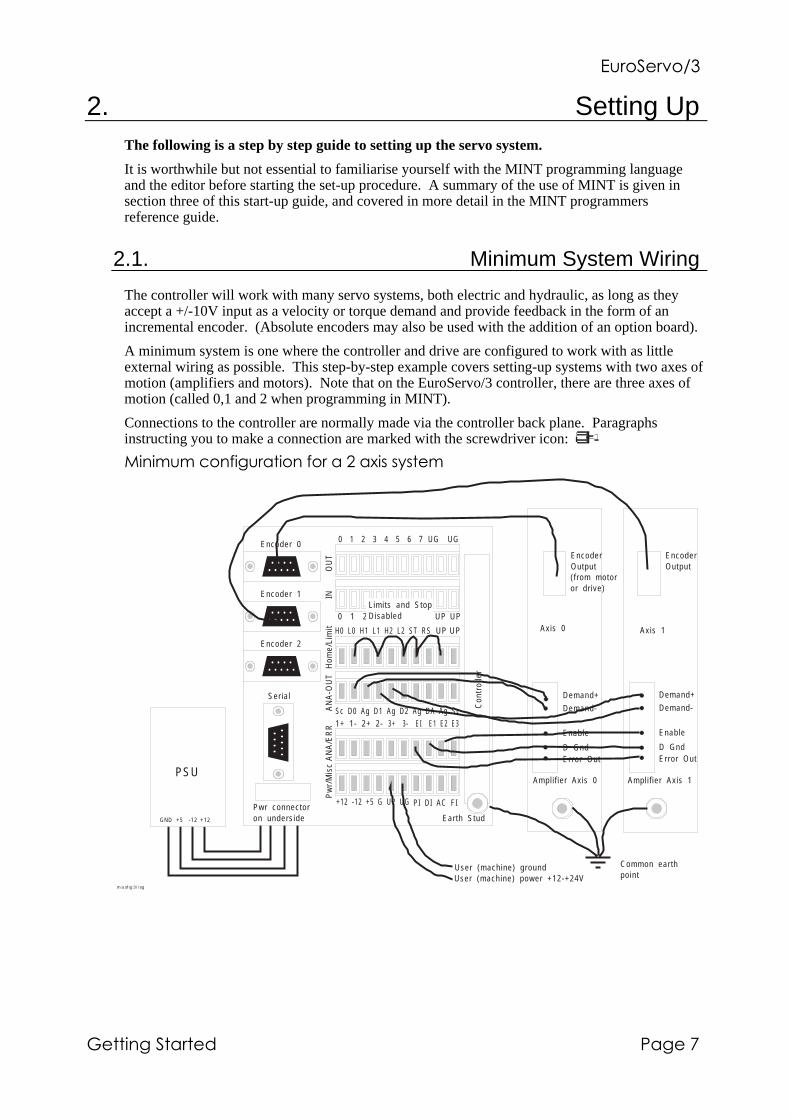
2.1. Minimum System Wiring
The controller will work with many servo systems, both electric and hydraulic, as long as theyaccept a +/-10V input as a velocity or torque demand and provide feedback in the form of anincremental encoder. (Absolute encoders may also be used with the addition of an option board).
A minimum system is one where the controller and drive are configured to work with as littleexternal wiring as possible. This step-by-step example covers setting-up systems with two axes ofmotion (amplifiers and motors). Note that on the EuroServo/3 controller, there are three axes ofmotion (called 0,1 and 2 when programming in MINT).
Connections to the controller are normally made via the controller back plane. Paragraphsinstructing you to make a connection are marked with the screwdriver icon:
/����#��(��0��#�&�����0���&� �&1���������
masfig3/isg
+12 -12 +5 G UP UG
Encoder 0
Encoder 1
Encoder 2
1 2 3 4 5 6 70 UG UG
Sc D0 Ag D1 Ag D2 Ag DA Ag Sc3+ 3- EI E1 E2 E3
Earth Stud
1 2 3 4 5 6 70 UP UP
H0 L0 H1 L1 H2 L2 ST RS UP UP
1+ 1- 2+ 2-
PI DI AC FI
INO
UT
Hom
e/Li
mit
AN
A-O
UT
AN
A/E
RR
Pw
r/M
isc
Con
trol
ler
Demand+
Demand-
Enable
D GndError Out
Ampl i f ier Axis 0
Demand+
Demand-
Enable
D GndError Out
Ampl i f ier Axis 1
Ser ial
Pwr connectoron undersideGND +5 -12 +12
PSU
User (machine) groundUser (machine) power +12-+24V
Limits and StopDisabled
Common earthpoint
EncoderOutput
EncoderOutput
Axis 0 Axis 1
( f rom motoror dr ive)

�#�����"�$%
'&���� ����������&����
2.1.1. Power Connections: "Pwr/Misc" screw Connector
The controller has opto-isolation between the microprocessor controller and the inputs and outputsto provide noise immunity required for industrial environments. This means that it has twoseparate power supply inputs, including isolated grounds. The controller power supplyrequirements are: +5V @ 0.5A (labelled "+5" on the connector), +12V @ 100mA "+12" and -12V@ 100mA "-12" and ground "G". In addition, the opto-isolated side of the outputs requires powerwhich can be provided by the machine power supply, "UP" (user power on the connector) can be+12V to +24V and there is also an isolated ground connection "UG" (user ground).
UG PI DI AC FI+12 -12 +5 G UPP
wr/
Mis
c
If not a rack system with internal power supply already fitted, connect +12V,-12V,+5V andG (0V) on the "Pwr/Misc" connector to a stabilised three rail power supply with at least 1Acapacity on the 5V line.
If a rack system, you simply have to wire up the euro-plug supplied with the rack to a singlephase AC supply of between 85VAC and 265VAC, 50 or 60Hz.
In rack systems, power is connected to the controller back plane via a connector on the undersideof the connector.
Connect UP (user power) to the external machine power supply of 12V to 24V, on the lowerscrew connector labelled "Pwr/Misc". Connect UG (user ground) to the machine 0V orground. These inputs are the power connections for the opto-isolated side of the controllerinput/output. If galvanic isolation is not required, and/or another power supply is notavailable, then connect UP to +12V and UG to G by making links across the terminals onthe connector.
2.1.2. Limit and Stop Switches: "Home/Limit" Connector
The limit switch inputs are usually connected through normally closed over-travel switches on theend of the axes of motion and cause motion to stop when floating. To allow motion they musthave power supplied to them; usually thorough normally closed switches on the axes. If two limitswitches are connected to one axis, they must be wired in series. This arrangement means thatthe controller is fail safe, if a wire breaks, the controller stops motion.
The Stop switch input causes all axes to decelerate to a halt and is used for connection to machineguards. This also must have power supplied to the switch in order to allow motion.
For the purposes of setting up the controller, these inputs can be linked out on the back plane:
H0 L0 H1 L1 H2 L2 ST RS UP
Hom
e/Li
mit
Remove the screw connector labelled "Home/Limit" and connect L0 (limit axis 0), L1, L2,ST (stop motion input) to UP (user power). Use insulated thin gauge wire for theconnections.
If the limit or stop inputs are not properly connected, the controller will display an "L" or an "S"on the status display on the front of the board on power up.
�#�����"�$%
����������&���� '&����
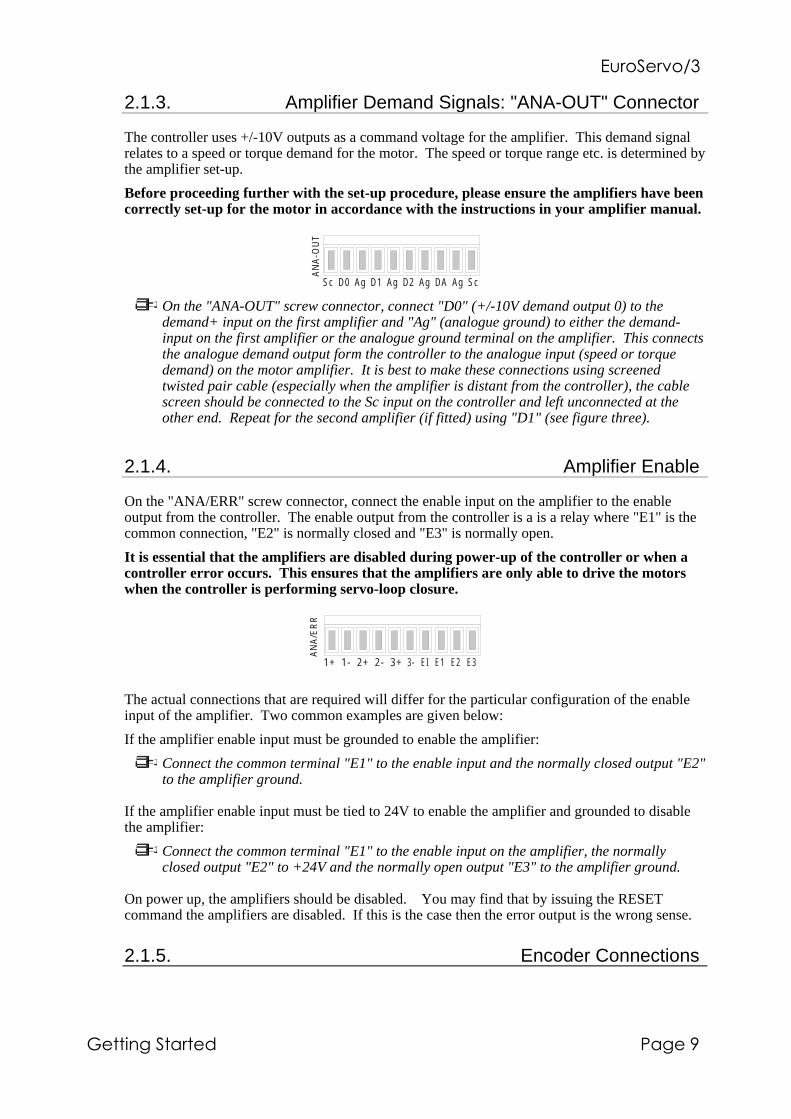
2.1.3. Amplifier Demand Signals: "ANA-OUT" Connector
The controller uses +/-10V outputs as a command voltage for the amplifier. This demand signalrelates to a speed or torque demand for the motor. The speed or torque range etc. is determined bythe amplifier set-up.
Before proceeding further with the set-up procedure, please ensure the amplifiers have beencorrectly set-up for the motor in accordance with the instructions in your amplifier manual.
Sc D0 Ag D1 Ag D2 Ag DA Ag Sc
AN
A-O
UT
On the "ANA-OUT" screw connector, connect "D0" (+/-10V demand output 0) to thedemand+ input on the first amplifier and "Ag" (analogue ground) to either the demand-input on the first amplifier or the analogue ground terminal on the amplifier. This connectsthe analogue demand output form the controller to the analogue input (speed or torquedemand) on the motor amplifier. It is best to make these connections using screenedtwisted pair cable (especially when the amplifier is distant from the controller), the cablescreen should be connected to the Sc input on the controller and left unconnected at theother end. Repeat for the second amplifier (if fitted) using "D1" (see figure three).
2.1.4. Amplifier Enable
On the "ANA/ERR" screw connector, connect the enable input on the amplifier to the enableoutput from the controller. The enable output from the controller is a is a relay where "E1" is thecommon connection, "E2" is normally closed and "E3" is normally open.
It is essential that the amplifiers are disabled during power-up of the controller or when acontroller error occurs. This ensures that the amplifiers are only able to drive the motorswhen the controller is performing servo-loop closure.
3- EI E1 E2 E31+ 1- 2+ 2- 3+
AN
A/E
RR
The actual connections that are required will differ for the particular configuration of the enableinput of the amplifier. Two common examples are given below:
If the amplifier enable input must be grounded to enable the amplifier:
Connect the common terminal "E1" to the enable input and the normally closed output "E2"to the amplifier ground.
If the amplifier enable input must be tied to 24V to enable the amplifier and grounded to disablethe amplifier:
Connect the common terminal "E1" to the enable input on the amplifier, the normallyclosed output "E2" to +24V and the normally open output "E3" to the amplifier ground.
On power up, the amplifiers should be disabled. You may find that by issuing the RESETcommand the amplifiers are disabled. If this is the case then the error output is the wrong sense.
2.1.5. Encoder Connections

�#�����"�$%
'&����2 ����������&����
The encoders are the position sensors used by the controller to measure axis position. Theyconsist of two pulse trains, 90 degrees out of phase, the controller uses the phase difference todetermine direction of motion and counts the encoder edges to determine position.
The controller will work with three channel incremental encoders (CHA, CHB, INDEX) and withboth single ended TTL or differential line driver TTL output types. It is recommended that linedriver outputs be used in all applications, since this gives increased noise immunity. It isimportant that each encoder cable is screened independently and that the screen is connected atthe controller end only. Maximum cable length is dependent on the encoder specification, butshould be kept as short as possible.
In many brushless amplifiers, the motor is fitted with a resolver and the encoder signal issynthesised by the amplifier. In these instances, the encoder connections are wired to theamplifier rather than the motor.
When making connections to encoder outputs from a brushless drive, do not connect the+5V supplies on the controller and amplifier together since this may cause noise problems.
The encoder should be wired to a 9 pin 'D' male plug, using good quality multi-corescreened cable, according to the following diagram. If the encoder is a single-ended type(i.e. no compliment outputs) leave the !CHA, !CHB and !INDEX pins unconnected. If theencoder does not have a compliment (Z) output, leave the INDEX and !INDEXunconnected.
5 4 3 2 1o o o o o
o o o o9 8 7 6
CHA SCRN !CHB INDEX +5V
!CHA CHB GND !INDEXmasfig4/isg
Pin No. Signal Name Function Type1 +5V Power to Encoder Output2 INDEX Index Mark Input3 !CHB Channel B Compliment Input4 SCRN Cable Screen Input5 CHA Channel A Input6 !INDEX Index Complement Input7 GND Signal Ground8 CHB Channel B Input9 !CHA Channel A Compliment Input

�#�����"�$%
����������&���� '&�����
2.1.6. Ground Connections
A good ground connection to the controller is essential for noise immunity in industrialenvironments, bad earth can be the cause of many strange problems, for instance loss of motorposition.
Connect the earth stud on the controller and amplifiers to a common earth point usingheavy duty cable. Make sure that the connection is in a 'star' configuration as shown in theminimum system wiring diagram.
2.1.7. Serial Cable
The RS232 cable is used to connect the controller to a computer for programming and systemcommissioning. A computer is not essential for operation of the controller, but required forprogramming. Use a standard serial cable or build one up according to the wiring diagram in theHardware manual.
Please note that the RS232 specification is a 'standard' that varies from manufacturer tomanufacturer and therefore not all RS232 cables will work with the controller.

�#�����"�$%
'&���� ����������&����
2.2. Testing System Wiring
In order to check that the encoder, tacho (if connected) and motor are wired up correctly, it isrecommended that the motor is tested and commissioned 'on the bench' and not in situ.
In order to verify that the system is wired up correctly, the following steps should be performed:
1 Check that error output (enable) is the correct sense.
2 Check encoders work.
3 Check the amplifier is working.
4 Check encoder and motor are connected the right way round.
5 Set-up system gains for satisfactory closed loop control.
The program examples in this manual are contained on the cTERM disk that is enclosed with themanual. The disk icon is used to indicate a program (each program is enclosed in a box) the nameunder the disk icon indicates the name of the program on the disk. These programs can bemodified by the use of an external editor or by use of the on-board editor on the controller.Typing RUN will execute the programs. Single line examples can entered direct at the commandline for immediate execution, indicated by the prompt icon: 0
2.2.1. Starting cTERM
The cTERM disk contains a program for IBM compatibles that makes the computer work like aterminal emulator. A terminal emulator program accepts character input from the computerkeyboard and sends these characters down the serial port so that they can be interpreted andprocessed by the controller microprocessor. The terminal emulator program displays anyinformation that is sent back from the controller on the computer screen. Therefore, you use theterminal emulator program to 'talk' to the controller. For example, if you press the "A" key on thekeyboard, an "A" character is sent down the serial port and the controller responds by sending thesame character back which appears on the computer screen. Of course, it all happens so quicklythat you don't notice any delay between typing the character and it appearing on the screen.
The terminal emulator therefore allows you to create programs in the memory of the controller bytyping them into an IBM compatible computer, using the editor on the controller.
A number of other features are available within the cTERM program, for instance, the ability touse your favourite editor on the computer to create programs for the controller and then downloadthese at the press of a button. These features are covered in the cTERM manual.
To run cTERM, insert the disk in your 3.5" floppy disk drive slot (drive A: or B:). Log-on to thatdrive by typing "A:" or "B:" followed by return, then type "cterm" and press return.
Details of using cTERM are given in the manual APPLICATIONS AND UTILITIESDISKETTE. Please familiarise yourself with operation of cTERM, especially up anddownloading of files, by reading section two of this guide before you proceed further.
Experienced computer users who have a fixed disc drive may wish to copy all the files on thecTERM disk into a directory their fixed disk.
Next plug your serial cable into COM1 in the back of the computer, and into the 'D' type marked"Serial Port" on the controller back plane, or into the front of the controller (which is a duplicateof the connections on the back plane).

�#�����"�$%
����������&���� '&����%
Plug the power lead into the euro-socket on the back of the control system rack and switch-on.The controller should power-up and the message:
c3MINT vX.XX
C>
Should be displayed on the computer screen and also on the LCD display in the rack if fitted. Ifthis is not the case, check the wiring of the serial cable and refer to the Trouble-Shooting sectionin the back of this guide.
2.2.2. Example Programs
Throughout this section example programs are given, identified by the disk icon: �
Under the disk icon, the file name is given and this file can be found on the cTERM disk in thedirectory /APPS, for you to download to the controller. Some files names have ".MNT" after thename which indicates that they are MINT program files and should be downloaded to the programstorage space on the controller. Others, have ".CFG" after the filename, which indicates that theyare configuration files and should be downloaded to the controller configuration storage space.Details of how to download are given in the cTERM manual called APPLICATIONS ANDUTILITIES DISKETTE, more information on configuration and program files is given in section3 of this guide.
MINT has a integral editor than can be used to make simple changes to program and configurationfiles. Details of using the on-board editor is given in section 10 of the MINTPROGRAMMING GUIDE, it would be worthwhile to spend a few minutes familiarisingyourself with operation of the editor before proceeding.

�#�����"�$%
'&����) ����������&����
2.2.3. Checking the Encoder
The encoder records the position of the motor in a positive and negative direction. The followingprogram can be used to check that the encoder is functioning correctly (assuming a 2 axis servosystem):
�������!/��
AXES[0,1]
RESET[0,1,2]
GN = 0; : REM Set all the gains to zero
KV = 0;
KI = 0;
KF = 0;
ABORT : REM Disable the amplifier
LOOP
PRINT POS[0];POS[1]; : BOL
ENDL
To download the program to the controller, load cTERM, press F3 and type the program name:"encoder" in the PROGRAM box; then press return. cTERM should indicate that the programhas downloaded successfully or will display an error message in the event of a fault. Press F10 togo into the terminal screen and type "RUN" (press return) this should start execution of theprogram.
The program works by setting all system gains to zero and disabling the amplifiers so that themotor shaft can be moved by hand. If the amplifier is not disabled, check the connection of theenable output from the controller. Alternatively, disconnect the amplifier ensuring that theencoder is still powered up.
The program will print the position (encoder value) of axes 0 and 1 to the terminal. By movingthe motor backwards and forwards you should see the position change. Note that the controlleruses quadrature decoding which gives 4 counts for each line of the encoder disk. With a 250 lineencoder, the position should change by ±1000 for every revolution moved clockwise or anti-clockwise. If the position does not change then check the following:
• Axis 0 encoder cable is connected to encoder input 0 and axis 1 encoder cable is connectedto encoder input 1.
• Encoders have power.
• The encoders are correctly wired up.
Make a note of which direction gives an increase in position. Repeat for other axes.
To check the index (marker) pulse, see a later section.

�#�����"�$%
����������&���� '&����,
2.2.4. Checking Motor Polarity
To confirm the polarity of the motor connections, use the TORQUE command as shown (refer tothe MINT Programming Guide for further details on the TORQUE command):
P> TQ = 1
Starting with a value of 1, increase the torque value until the motor starts to move. The motorshould move in a positive direction i.e. the position (encoder) should increase. Download andRUN the following program can be used to check this:
��/���!/��
RESET[0,1,2]
SERVOFF[1]
TQ[0] = 1 : REM Increase until motor moves
LOOP
? POS[0]; : BOL
ENDL
Tip: you will need to use MINTs editor to change line 3 of this program. From the "P>" you cando this by typing:
P> EDIT 3
After making changes to the line, press return to finish. If the "C>" prompt is displayed, you canchange to the program file by typing :
C> PROG
If the position decreases, swap the motor cables over or swap the A and B channels on theencoder, first removing power from the amplifier. Repeat the operation.
Repeat the operation with a negative value of torque, for example:
P> TQ = -1
The position should now decrease. Repeat the operation for the other axes.
If the motor does not move with a torque value of 100 (100% demand output) check the following:
• The amplifier is enabled.
• The motor is connected.
• The amplifier is correctly configured.
• The controller is correctly connected to the amplifier
More suggestions are given in the fault finding guide at the back of this manual.
�#�����"�$%
'&����- ����������&����
2.3. Setting System Gains
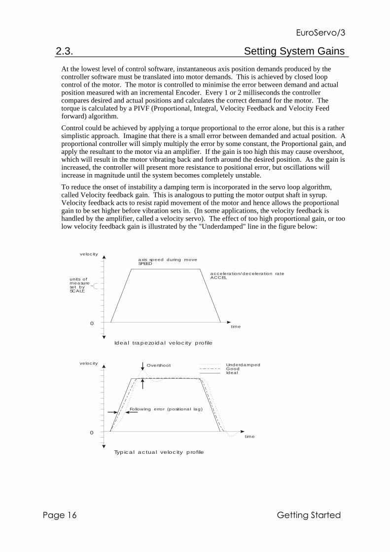
At the lowest level of control software, instantaneous axis position demands produced by thecontroller software must be translated into motor demands. This is achieved by closed loopcontrol of the motor. The motor is controlled to minimise the error between demand and actualposition measured with an incremental Encoder. Every 1 or 2 milliseconds the controllercompares desired and actual positions and calculates the correct demand for the motor. Thetorque is calculated by a PIVF (Proportional, Integral, Velocity Feedback and Velocity Feedforward) algorithm.
Control could be achieved by applying a torque proportional to the error alone, but this is a rathersimplistic approach. Imagine that there is a small error between demanded and actual position. Aproportional controller will simply multiply the error by some constant, the Proportional gain, andapply the resultant to the motor via an amplifier. If the gain is too high this may cause overshoot,which will result in the motor vibrating back and forth around the desired position. As the gain isincreased, the controller will present more resistance to positional error, but oscillations willincrease in magnitude until the system becomes completely unstable.
To reduce the onset of instability a damping term is incorporated in the servo loop algorithm,called Velocity feedback gain. This is analogous to putting the motor output shaft in syrup.Velocity feedback acts to resist rapid movement of the motor and hence allows the proportionalgain to be set higher before vibration sets in. (In some applications, the velocity feedback ishandled by the amplifier, called a velocity servo). The effect of too high proportional gain, or toolow velocity feedback gain is illustrated by the "Underdamped" line in the figure below:
time
velocity
acceleration/deceleration rateACCEL
0
axis speed during moveSPEED
units ofmeasureset bySCALE
Ideal trapezoidal velocity profile
time
velocity
0
Typical actual velocity profile
Overshoot
Following error (positional lag)
UnderdampedGoodIdeal

�#�����"�$%
����������&���� '&����.
When the motor is stationary at a set point there may be a small positional error. The controllermultiplies the error by the proportional term to produce an applied corrective torque (in currentcontrol), but for very small errors the torque may not be large enough to overcome static friction.Therefore integral action is also incorporated in the loop calculations, this involves summing theerror over time so that the torque may be gradually increased until the positional error falls tozero. The speed at which integral action works is controlled by the Integral gain. Integral actionis useful to eliminate steady state positional errors, but will result in reduced dynamic response forthe system.
The final term in the control loop is Velocity feed forward. This is useful for increasing theresponse and reducing the following error.
Two types of servo amplifiers may be used with the controller:
• Current or torque amplifiers use the demand signal to control the current flowing in themotor armature and hence the torque of the motor.
• Velocity controlled amplifiers (velocity servo) uses the demand signal as a servo speedreference.
For general purpose applications, the torque amplifier is cheaper and simpler to set up, but thevelocity servo gives better control, especially in high performance applications. For torqueamplifiers, velocity feedback must be used to stabilise the system, but this is not normally requiredfor a velocity servo since it incorporates its own internal velocity feedback.
A block diagram of the complete control loop, showing controller, amplifier, motor and gearbox ispresented below. The servo amplifier may be a simple current amplifier, or incorporate internalvelocity feedback via a tachometer:
+
_
KVELVelocityFeedback
ActualPos i t ion
FOLERRFol lowingError
POS
VELActual Velocity
KVELFFVelocityFeedforward
GAINProport ionalGain
KINT Integral Gain+
_
+
+
Integrator
InstantaneousDemand Pos it ion
Demand SpeedInstantaneous
KINTRANGE Int . l imit
+
PowerAmpl i f ier
ServoMotor
Analogue velocityfeedback
Current or speedDEMAND
D to AconverterCURRLIMITcurrent l imit
Prof i le
t ime
speed
High level pos i t ionor speed demand
MINTMot ion
Interpreter
Generator
Revs
OutputShaft
Tachometer(opt ional)
Channel AChannel B
QuadratureDecoder(4x pulses)
+/- 10Vanalogue
EncoderPos i t ionCounter
masfig5/isg
���"����� �*��(+���&��&�����3��������"&���/����+��3��������(& ��&��!

�#�����"�$%
'&����� ����������&����
You see that we have a four term controller incorporating proportional, velocity feedback/feedforward and integral gains.
The equation of the loop closure algorithm is as follows:
Demand = GN.e - KV.v + KF.V + KI. Σe
e - following error (quad counts)v - actual axis velocity (quad counts/sample time)V - demand axis velocity (quad counts/sample time)
Keyword Abbreviation DescriptionGAIN GN Proportional servo loop gain
KVEL KV Velocity feedback gain
KVELFF KF Velocity feed forward gain
KINT KI Integral feedback
Tuning the drive involves changing the four servo loop gains, GN, KI, KV and KF to provide thebest performance for your particular motor/encoder combination and load inertia. In view of thediversity of application, these values all default to zero and should be set up in the systemconfiguration file.
Two other keywords, KINTRANGE and CURRLIMIT, are used to control the demand output.KINTRANGE, the integration limit, determines the maximum value of the effect of integralaction, KI.Σe. KINTRANGE is specified as a percentage (%) of the full scale demand output inthe range of ±10V. Therefore if KINTRANGE = 25, the maximum effect of integral action is±2.5V.
CURRLIMIT, the current limit, so called for its use with current amplifiers, determines themaximum value of the demand output as a percentage of the full scale demand. Therefore ifCURRLIMIT = 50, the maximum demand output will be ±5V.
The encoder gain (measured in pulses/rev) is one factor that is hardware dependant but has adirect effect on the overall loop gain. The other parameters are software controlled in the range of0.0-255.0, the resolution of the decimal part is one part in 256 as with normal MINT variables (seethe MINT Programming Guide for an explanation of scaled integers).
All servo loop parameters default to zero, so the motor will have no power applied to it on powerup. Most servo amplifier can be set up in either current (torque) control mode or velocity controlmode. The procedure for setting system gains differs slightly for each.
2.3.1. System Gains for Current Control by Empirical Method
After you have confirmed that the encoder and motor are correctly wired up, you should start byapplying some derivate gain, KV. Start with a value of 1 and increase it until you feel someresistance in the motor.
For some motors, it may be necessary to apply fractional gains, all gain terms are floating pointnumbers.
Once the feedback gain has been set, apply some proportional gain, GN. Start off with a valuewhich is a quarter of the feedback gain i.e.. GN = KV / 4. If the motor starts to vibrate, increasethe velocity feedback gain (damping), KV, or decrease the proportional gain, GN. Increaseproportional gain, GN, until the motor shaft becomes stiff.

�#�����"�$%
����������&���� '&�����
Finally, set the velocity feed forward gain, KF, to the same value as the velocity feedback gain,KV.
An alternative to using KV and KF is to use the derivative term, KD. KD has exactly the sameeffect on the system dynamics as KV when KV=KF.
2.3.2. Fine Tuning System Gains
The above 'rules of thumb' for setting system gains, whilst adequate to get the system moving, willnot provide the optimum response without further fine tuning of the system gains. The basic aimhere is to set the Proportional Gain as high as possible without getting overshoot or instability orhunting (buzzing) on an encoder edge when stationary.
This is best achieved by attempting some short positional moves (say one revolution of the motor)with high accelerations and speeds and observing the response on an oscilloscope. Theoscilloscope is normally connected to a tachometer on the motor, however with NextMove asoftware scope is available as part of the set-up program.
2.3.3. Eliminating Steady-State Errors
In systems where precise positioning accuracy is required, it is often necessary to position towithin one encoder count. Proportional gain, GN, is not normally able to achieve this because avery small following error will only produce a small demand for the amplifier which may not beenough to overcome mechanical friction (this is particularly so for current controlled systems).This error can be overcome by applying some integral gain.
The integral gain, KI, works by accumulating following error over time to produce a demandsufficient to move the motor into the zero following error position. KI can therefore alsoovercome errors caused by gravitational effects, such as veritcally moving linear tables, wherewith current controlled drives a non-zero demand output is required to acheve zero followingerror.
Particular care is required when setting KI since a high value can cause instability during moves.The effect of KI should be limited by setting the maximum range of the integration (using the KRkeyword) to the minimum value which is sufficient to overcome friction or static loads. Typicalvalues are:
KR = 5
KI = 0.1
where KR limits the integral term to 5% of the full DAC output range. KI is usually a factor of 10less than proportional gain, GN. With NextMove, it is possible to set the Intgrator such that it haszero effect on the system during motion and therefore does not affect system dynamics.
2.3.4. System Gains for Velocity Control
Velocity controlled drives incorporate the velocity feedback term in the amplifier which providessystem damping and therefore it is usually sufficient to have KV = KD = 0 on the controller.
Usually, the value of the proportional gain, GN, will be less than with an equivalent currentcontrolled system. Often a fractional value of proportional gain gives the best response. Forexample:
GN = 0.25

�#�����"�$%
'&��� 2 ����������&����
Correct setting of the velocity feed forward gain, KF, is important to get maximum response fromthe system. This is best performed using a storage oscilloscope to record the tacho output for fastpoint-to-point moves. This enables you to see the velocity/time profile for the motor in order tomonitor actual acceleration and overshoot.
Referring to the servo loop block diagram, the velocity feed forward term is a block which takesthe instantaneous speed demand from the profile generator and adds this to the output block.Because KF is a feed forward term, a very important difference between this and the other termsexist. KF is outside the closed loop and therefore does not have an effect on system stability.This means that the term can be increased to maximum without causing the motor to oscillate,provided that the other terms are set-up correctly.
In practice however, a very high value of KF is of no benefit to system performance. Instead, itmust be set such that a demand of ω RPM from the profile generator results in a demand output tothe velocity drive which gives ω RPM on the motor shaft (i.e. a 1:1 relationship).
When set-up correctly, KF will cause the motor to move at the demand speed from the profilegenerator. This is true without the PID terms in the closed loop doing anything exceptcompensating for small errors in the position of the motor due to analogue drift. This gives fasterresponse to changes in demand speed, with lower following errors.

�#�����"�$%
����������&���� '&��� �
�1&� ���(&�(#�&������0�45��667
In order to calculate the correct value for KF, you need to consider the workings of the servo loopclosure algorithms. In the servo loop, speeds are expressed in quadrature counts/servo loopclosure time. For instance, a speed of 100 is 100 counts every 250µS in the standard controller.(It is possible to set the controller to a 1mS sample time using the LOOPTIME keyword - see theMINT programming guide for further information).
In this example the velocity of the servo is 3000RPM with a +10V input, and the encoder has 500counts per revolution.
In this example the velocity of the servo is 3000RPM with a +10V input, and the encoder has 500counts per revolution.
At 3000RPM we require an analogue voltage of +10V. This relates to:
3000
6050= revs per second
Now we can calculate the number of quadrature counts per loop closure time by using theexpression:
speed_ in_ revs * encoder_ line_ count * 4
number_ of _ loop_ closures_ per_ second
The factor of 4 is included since the controller counts every edge of the pulse train coming fromthe encoder a and B channels, which gives four times better resolution than the number of lines.
50 * 500 * 4
500= 200 quadrature counts per servo loop closure time
(Note: for 1 mS loop closure time, this expression becomes: 50*500*4/1000).
The DAC output has a resolution of 12 bits over the range -10V to +10V, therefore +10V = 2048counts.
The feed forward term is therefore given by:
KVELFF = =2048
20010 24.
Increasing KF above the calculated value will cause the controller to have a following error aheadof the desired position. Decreasing KF below this value will cause the controller to have a morenormal following error behind the desired position. The calculated value above should give zerofollowing error in normal running.
You can investigate the effect of velocity feed forward gain by jogging the motor at constantspeed and printing out the following error, FE, for different values of KF. When attempting thismake sure that you have zero integral gain since this will cause the following error to tend to zerounder steady state conditions, thereby negating the effect of changes in KF.

�#�����"�$%
'&��� ����������&����
2.3.5. The Configuration File
The configuration file is used to store all the defaults appropriate to the particular system. Oncegains and speeds have been found, these should incorporated into a configuration file for yoursystem.
Whenever the program is RUN, the configuration file is first executed. A list of parameters thatyou may need to set up follows:
• Servo loop gains - to tune the system response.
• Scale factor - to set the units of measure of the application - see MINT PROGRAMMINGGUIDE for details of using SCALE.
• Maximum following error (MFOLERR) - to set a safe maximum difference between actualand desired positions.
• Default speeds (SPEED) and accelerations (ACCEL) for the system - to determine theshape of the trapezoidal velocity profile (RAMP).
These parameters are generally be set up only once for an application, but can at any time bealtered in the Program File.
A typical Configuration file for a three axis system is:
�����6��!�6�
AUTO : REM automatic execution on power up
REM Config file for XYZ system
RESET[0,1,2] : REM to ensure previous setting cleared
AXES[0,1,2]: : REM 3 axis servo system
REM system gains
GAIN = 10;
KVEL = 40;
KF = KVEL; REM assuming a torque amplifier
REM position/SPEED parameters
SCALE = 2000; : REM units revs (500 line encoder with 4x multiplication)
SPEED = 60; : REM max SPEED 60 revs/sec
ACCEL = 150; : REM max accel 150 revs/sec^2
MFOLERR = 1; : REM 1 rev maximum following error
In the above example, the default axis list is 0,1,2 the semicolon is used to apply all theparameters to all three axes, see the MINT PROGRAMMING GUIDE for further details onprogram language syntax.
Please note that the values for gains, speeds etc. are given only as an example. It is up to youto determine the best values for your system.
To download the example configuration file type F3 from within the cTERM terminal emulatorand select "CONFIG", then type the example configuration file name: CONFIG. You can thenuse the MINT editor to change the values to those that you have identified during the set-upprocedure.

�#�����"�$%
����������&���� '&��� %
2.4. Encoder Marker Pulse
With the amplifiers configured with the correct gains, it is now possible to check the marker pulseon the encoder. This is achieved using the MINT HOME command as follows:
P> HOME = 6
will seek the index pulse in a positive direction. If the motor does not stop after more than 1revolution, check the wiring on the encoder.
Using the command:
P> HOME = 4
The motor should rotate in a negative direction and stop at the marker pulse. Repeat for otheraxes.

�#�����"�$%
'&��� ) ����������&����
3. Introduction to MINT Programming Language
3.1. Your First MINT Program
MINT is the programming language used to program the controller to meet the requirements ofspecific applications. MINT provides control of the I/O and motion control aspects of thecontroller using BASIC like programming structures and keywords. You may have an applicationwhere a thumbwheel switch, fed into the digital inputs of the controller, sets a distance to moveand a potentiometer, fed into one analogue input on the controller, changes the slew speed. Asimple MINT program would be written to achieve this.
MINT programs consist of two files. The configuration file stores information relating to themachine set-up, for instance the servo loop gains. The program file stores the actual motioncontrol program. In fact the two files are the same and can contain the same instructions, exceptthe configuration file is only 1K maximum size, whilst the program file can be up to 27K. Inaddition there is a third method of storing information in the controller, in the form of array data,which can be used as variables within a program (more information about this is given in theMINT programming guide).
This first MINT program consists of a simple configuration and program file which is used toindex a motor a set distance entered via a computer or via the operator keypad. The configurationand program files can be found on the APPLICATIONS AND UTILITIES DISK in the directory/APPS.
The program file is called FIRST.MNT and the configuration file is called FIRST.CFG. Theexample has been written for a single axis of motion, connected to axis 0 of the controller.
��6���!�6�
REM File name: first.cfg
REM Configuration file for first MINT program
AXES[0] REM This program only uses axis 0 (the first axis)
RESET[0,1,2]
SCALE = 2000 REM Scale factor for revs assuming 500 line encoder (500*4)
GAIN = 1 REM Servo gains - these should be changed to the values..
KVEL = 5 REM .. found during servo set-up
KINT = 0
KF = KVEL
SPEED = 50 REM Default speed during positional moves 50 rev/s
ACCEL = 200 REM 200 rev/s^2
END
Any characters after a REM (remark) statement are ignored, which allows you to insert commentsin the program to make it more readable at a later date. It is important to keep back-up copies ofyour programs and configuration files on disk, the first line of this program indicates the namethat we have given to the disk file. Download this configuration file to the controller as explainedin the APPLICATIONS AND UTILITIES DISKETTE manual. Remember that you may haveto change the gains and scale factor to suit your motor.
�#�����"�$%
����������&���� '&��� ,
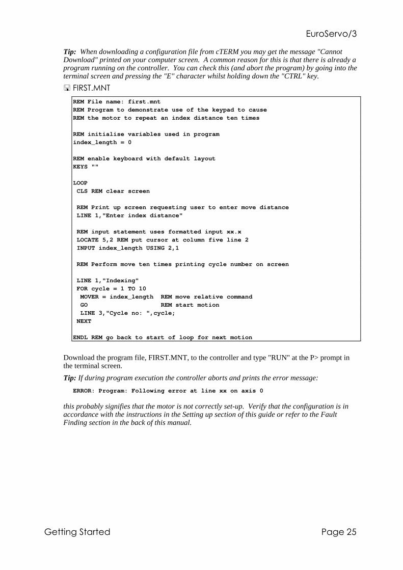
Tip: When downloading a configuration file from cTERM you may get the message "CannotDownload" printed on your computer screen. A common reason for this is that there is already aprogram running on the controller. You can check this (and abort the program) by going into theterminal screen and pressing the "E" character whilst holding down the "CTRL" key.
��6���!/��
REM File name: first.mnt
REM Program to demonstrate use of the keypad to cause
REM the motor to repeat an index distance ten times
REM initialise variables used in program
index_length = 0
REM enable keyboard with default layout
KEYS ""
LOOP
CLS REM clear screen
REM Print up screen requesting user to enter move distance
LINE 1,"Enter index distance"
REM input statement uses formatted input xx.x
LOCATE 5,2 REM put cursor at column five line 2
INPUT index_length USING 2,1
REM Perform move ten times printing cycle number on screen
LINE 1,"Indexing"
FOR cycle = 1 TO 10
MOVER = index_length REM move relative command
GO REM start motion
LINE 3,"Cycle no: ",cycle;
NEXT
ENDL REM go back to start of loop for next motion
Download the program file, FIRST.MNT, to the controller and type "RUN" at the P> prompt inthe terminal screen.
Tip: If during program execution the controller aborts and prints the error message:
ERROR: Program: Following error at line xx on axis 0
this probably signifies that the motor is not correctly set-up. Verify that the configuration is inaccordance with the instructions in the Setting up section of this guide or refer to the FaultFinding section in the back of this manual.
�#�����"�$%
'&��� - ����������&����
3.1.1. Program Narrative
The first MINT statement in the file (that is not a comment) is the line:
index_length = 0
this defines a variable called index_length and initialises it to the value 0. index_length is usedlater in the program to store the length of move entered by the operator. The second MINTstatement:
KEYS""
is used to initialise (turn on) the keypad interface on the controller. The KEYS command can beused to set-up the layout of any 8x8 matrix keyboard, but this example uses the default layoutwhich is that of the standard 27 key operator keypad.
The operator keypad works just like a standard serial terminal. Pressing any of the keys on theterminal causes a character to be placed in the serial port buffer so that it can be read by theprogram by using the INPUT, INKEY keywords etc. that can be found in the popularprogramming language BASIC on which MINT was based. Similarly the keyword PRINT can beused to output data to the 20 character by four line LCD screen on the operator keypad.
The LOOP statement in the program signifies the start of a loop from which the program neverexits. It simply marks the point to which the program jumps when it encounters the ENDLstatement.
After clearing the terminal screen of any erroneous information printed by previous programs(CLS). The next statement:
LINE 1,"Enter Index Distance"
prints a message on line one of the terminal. The LINE keyword was specially written to makeprinting information on the LCD display easy. Note that you could equally use the standardBASIC LOCATE and PRINT statements to do this; i.e.:
LOCATE 1,1
PRINT "Enter index distance"
The LINE keyword however ensures that there are no characters left on that line from previousPRINT statements, even if the text string printed is less than 20 characters (the width of thescreen).
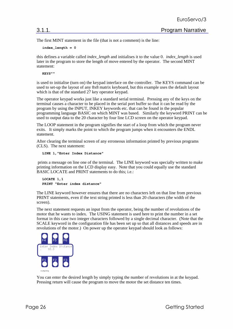
The next statement requests an input from the operator, being the number of revolutions of themotor that he wants to index. The USING statement is used here to print the number in a setformat in this case two integer characters followed by a single decimal character. (Note that theSCALE keyword in the configuration file has been set up so that all distances and speeds are inrevolutions of the motor.) On power up the operator keypad should look as follows:
F4 F5 F6
F1 F2 F3
masfig16/isg
You can enter the desired length by simply typing the number of revolutions in at the keypad.Pressing return will cause the program to move the motor the set distance ten times.

�#�����"�$%
����������&���� '&��� .
Tip: It often helps if there is a BEEP at the keypad whenever a key is hit, since this gives theoperator audible feedback that he has hit the key. You can do this by putting the statementBEEPON in the program.
The motor movement is achieved by the statement:
MOVER = index_length
GO
MOVER is a relative positional move, it causes the motor to move the number of revolutionsspecified using the accelerations and speed previously set up in the configuration file. The GOcommand is required to actually start the motion, it is useful if you need to synchronise bothrelative and absolute moves on two or more motors. GO is not required for certain types ofmoves, notably continuous speed control using the jog command.
You can see that the MOVER statement is surrounded by a FOR.. NEXT loop statement. Thiscauses the statements inside the loop to be executed 10 times, each time the number being storedin the variable cycle which is printed to the operator terminal each time round the loop.
Finally, program arrives at the ENDL statement, which causes it to jump back to the LOOPstatement so that you can enter the next index length. FOR .. NEXT and LOOP .. ENDL are twoexamples of the four different loop statements in the MINT language. These statements are veryuseful for writing machine control programs.
To end program execution, type the keys "CTRL-E" at the terminal screen.

�#�����"�$%
'&��� � ����������&����
3.2. A Simple Cut to Length Feeder
In many applications, the MINT programming language can be used to program the system as astand-alone machine controller. This program illustrates such a program for a simple cut-to-lengthmachine. The program allows the operator to enter a product length, feed speed and number offeed cycles and records the total length of product that has been cut.
If you have set-up the controller according to the instructions in the first part of this manual andyou have the standard controller with keypad, then it should be possible to get this program up andrunning within a few minutes, using one or two motors with their shafts in free air.
The program file FEEDER.MNT and the configuration file FEEDER.CFG can be found on thecTERM disk. Start cTERM and download these files to the controller as before and type RUN atthe P> prompt
�(���&��(��&��&���0������#������������6�����
Operator Panel
Servo controllerwith two axis servoamplifier
Cropped Product
Servo Motor andEncoder
Pinch DriveRollers
Product
Servo DrivenShear
masfig9/isg
F4 F5 F6
F1 F2 F3
XZ
Y
7 8 9 -
4 5 6 del
1 2 3 sp
0 . enter

�#�����"�$%
����������&���� '&��� �
3.2.1. � Configuration file FEEDER.CFG
AUTO REM Automatic program execution on power-up
REM File name: feeder.cfg
REM Configuration file for simple cut to length machine
CLS REM clear screen
PRINT "Please wait..."
AXES[0,1]
RESET[0,1,2]
SCALE = 50; REM 50 encoder counts = 1 mm on this application
GAIN = 10; REM Servo loop gains
KVEL = 40;
KF = KVEL;
KINT = 0;
SPEED = 4000; REM 4000 mm/s
ACCEL = 40000; REM 40000 mm/sec^2
RAMP = 0; REM no 's' ramping
END
The configuration file contains information specific to the servo system set-up. Detailedinformation of MINT command syntax is given in the MINT PROGRAMMING GUIDE.
The very top of the file contains the statement "AUTO". This command signifies that theconfiguration then program file should be run automatically on power-up. If automatic executionis required, AUTO must always be placed at the very start of the configuration file. When youturn the controller off, the program will be retained in non-volatile memory and on power-up themessage:
"Please wait ..."
will be displayed on the screen (printed on line 3) whilst the controller compiles and executes theprogram file. AUTO must always be on the first line of the configuration file, this is the onlyMINT command that cannot be used anywhere in a program or configuration file.
The statement "AXES[0,1]", indicates that the controller is fitted with two axes of motion and thatall commands thereafter will relate to these two axes unless explicitly indicated otherwise byenclosing the axis number in brackets are the command (e.g. SPEED[1] = 10 sets the speed of axis1 to 10, but SP = 10; sets the speed of both 0 and 1 to 10. Note the use of the semicolon to setboth axes to 10, otherwise you would have to type SPEED = 10,10).
Also note the inclusion of the RESET command. Whilst not strictly necessary, this ensures thatthe controller starts in a known state with all motion parameters and error flags reset to theirdefault values.
The code "SCALE = 50;" sets the system units in relation to the number of encoder quadraturecounts. If there were 50 counts per mm of linear movement, and you wanted to program speedsand distances in mm, you would set SCALE = 50.
The remainder of the file contains system gains and configuration information. These valuesmay have to be changed to achieve a stable system according to the particular motor/drivethat you are using - refer to section 2 of this guide for further information.
�#�����"�$%
'&���%2 ����������&����
3.2.2. � Program file FEEDER.MNT
REM File ... feeder.mnt
REM Author . Ivor Gillbe
REM Date ... 29-3-92
REM
REM Program to demonstrate use of the keypad in a cut to length machine
RESET[0,1,2] REM reset all motion parameters to default values
GOSUB initialise REM call initialise subroutine
GOSUB main_loop REM call main subroutine
END
#non_volatile
REM dummy definitions of variables stored in non-volatile RAM
REM this routine is not actually called and therefore the variables
REM are defined but not initialised to zero so that their programmed
REM values are retained
cycles = 0 REM number of material feed cycles
slew_speed = 0 REM speed of material feed
length = 0 REM amount of material feed
RETURN
#initialise
REM This subroutine sets up various parameters when program starts
KEYS "" REM enable keyboard with default layout
BEEPOFF REM turn off automatic keyboard beep
SPEED = slew_speed REM restore speed stored in non-volatile memory
count = 0 REM total length of material fed
jog_sp = 2000 REM default jog speed in manual mode
RETURN
#main_loop
REM This subroutine is the main program loop, it prints up the start-up
REM screen and handles operator selections by calling further subroutines
LOOP
REM Print up menu screen on four line operator display
REM Line 4 is the 'soft keys' for operator selection
LINE 1,""
LINE 2,"XYZ Widget Company"
LINE 3,"Press Feed Control"
LINE 4,"START SETUP MANUAL",
REM Read the key pressed into the variable 'key' and test to see if
REM the function keys (which return A B and C) are pressed
key=INKEY
IF key = 'a' THEN BEEP:GOSUB start REM call start subroutine
IF key = 'b' THEN BEEP:GOSUB setup
IF key = 'c' THEN BEEP:GOSUB manual
ENDL REM go back to top of loop
RETURN
�#�����"�$%
����������&���� '&���%�
REM This subroutine is manual mode allowing movement of roll back & forth
#manual
REM Print new menu where soft keys are FAST motion, SLOW motion and
REM EXIT to main menu
LINE 1,""
LINE 2,"Manual mode - press"
LINE 3,"'X' key to Jog roll"
LINE 4,"FAST SLOW EXIT",
jog_sp = 2000
LOOP
REM read softkey presses and set fast or slow motion or exit
key=INKEY
IF key = 'a' THEN BEEP : jog_sp = 2000 REM fast motion
IF key = 'b' THEN BEEP : jog_sp = 100 REM slow motion
IF key = 'c' THEN BEEP : EXIT REM program jumps to ENDL if true
REM This moves the motor back and forth using the arrow keys < and >
REM marked 'X'. READKEY is used to return the value of a key that
REM is pressed and held < returns the character 'x' and > returns 'u'
IF READKEY = 'u' DO
JOG = -jog_sp
ELSE IF READKEY = 'x' DO
JOG = jog_sp
ELSE
STOP REM button released - stop motor
ENDIF
ENDIF
ENDL
RETURN
REM Subroutine to allow operator to set-up product length, feed speed and
REM number of repetitions
#setup
REPEAT
LINE 1," EXIT"
LINE 2,"Setup menu"
LINE 3,"Select function"
LINE 4,"LENGTH SPEED CYCLES",
LOCATE 1,3
key=INKEY
IF key = 'a' THEN BEEP : GOSUB get_len
IF key = 'b' THEN BEEP : GOSUB get_sp
IF key = 'c' THEN BEEP : GOSUB get_cy
UNTIL key = 'f' REM end of REPEAT..UNTIL loop, terminates if 'f' pressed
BEEP : CLS REM beep and clear screen
RETURN
REM subroutine to get length of material
#get_len
CLS
LINE 1,"Enter index"
LINE 2,"distance:"
LINE 3," mm"

�#�����"�$%
'&���% ����������&����
BEEPON REM automatic keyboard beep on REM formatted input XXX.X
LOCATE 9,3 : INPUT length USING 3,1
BEEPOFF
RETURN
REM get number of feed cycles, up to 99 repetitions
#get_cy
CLS
LINE 1,"Enter number of"
LINE 2,"indexes required:"
BEEPON
LOCATE 9,3 : INPUT cycles USING 3
BEEPOFF
RETURN
REM subroutine to get speed, this example validates entered number to
REM make sure that it is less than 4000 and greater than 100
#get_sp
REPEAT
CLS
LINE 1,"Enter maximum"
LINE 2,"slew speed:"
LINE 3," mm/s"
LINE 4,"Range 100-4000mm/s",
number = slew_speed REM store before validating
BEEPON
LOCATE 9,3 : INPUT number USING 4
BEEPOFF
UNTIL number >= 100 AND number <= 4000
slew_speed = number REM if valid update variable and SPEED command
SPEED = slew_speed
RETURN
�#�����"�$%
����������&���� '&���%%
REM Run automatic cycle
#start
LOCATE 1,1
LINE 1," STOP"
LINE 2,"Machine Running"
LINE 3,"Cycle no:"
LINE 4,"Material:",
REM FOR .. NEXT loop executes n times where n = cycles
FOR index = 1 TO cycles
REM index material - move axis 0 distance given by length
MOVER[0] = length : GO[0]
PAUSE IDLE REM wait for previous move to finish
REM perform punch operation by moving axis 1 up and down
MOVEA[1] = 10 : GO[1]
MOVEA[1] = 0 : GO[1]
BEEP
count = count + length REM accumulate material fed
REM print status information
LOCATE 11,3 : PRINT index USING 2;
LOCATE 11,4 : PRINT count USING 5,1;
IF INKEY = 'f' THEN STOP : EXIT
NEXT REM end of FOR .. NEXT loop
REM End of programmed number of cycles
LINE 1," EXIT"
LINE 2,"Machine Stopped"
PAUSE INKEY = 'f'
BEEP
RETURN
#onerror
REM Error handling subroutine called by system in the event of excessive
REM following error (machine jam) or limit switch error
LINE 1,"****** Error ******"
LINE 2,"*** Machine Jam ***"
LINE 3,"*** Press Reset ***"
LINE 4,"RESET",
REPEAT
BEEP REM sound alarm buzzer continuously
UNTIL INKEY = 'a'
CANCEL[0,1,2] REM cancel error and re-run program
RUN
RETURN
#stop
REM Error handling routine called by system when STOP input (guard switch)
REM is asserted. Subroutine prints message on operator screen, then
REM returns to main program
LINE 2, "GUARD OPEN"
PAUSE STOP = 0 REM wait for guard to be closed
LINE 2, "Machine running"
RETURN

�#�����"�$%
'&���%) ����������&����
3.2.3. Cut To Length Program Narrative
The program has been written in a structured method to make it easy to maintain, according to thefollowing prototype:
REM program starts here
GOSUB init
GOSUB main
#init
...
RETURN
#main
...
RETURN
The program is well commented and therefore is fairly easy to follow. By making suitableadjustments to the SCALE factor and gains in the configuration file it should be possible to get theprogram working on any system equipped with a keypad and at least one axis of motion.
The #non_volatile subroutine is defined but never called. This is used to define some valueswhich we use in the program to store the product length etc. entered by the user. Because thesubroutine is never called they are never actually set to zero on power up and therefore the lastvalues entered by the user are retained.
The initialisation sub-routine, #init is called first. Initialisation sets up some defaults for thesystem, first enabling the keyboard with the KEYS" " keyword. The operator keyboard works inexactly the same way as a serial terminal, i.e. pressing a key causes the appropriate character to besent to the controller serial port buffer. The function keys labelled F1 to F6 return respectively thecharacters 'a' to 'f'. A legend can be printed to the LCD screen for each function key and thecorresponding character pressed checked in the program, giving a context sensitive 'soft key' typeoperator interface.
BEEPOFF causes the automatic beep on pressing a key to be turned off. The beep from thebuzzer is used to acknowledge a key press, this program is written so that a beep is only issuedwhen a valid (active function key) is pressed. The RETURN statement causes the program tojump back to the statement directly after "GOSUB init" the main loop is called.
The main loop simply prints up the following message on the LCD display:
F4 F5 F6
F1 F2 F3
masfig7/isg
Note the use of START, SETUP and MANUAL to create user definable legends for the functionkeys F1, F2 and F3 and the keypad. The routine then loops round checking to see if a key ispressed at the keyboard. F1, F2 and F3 return the characters "A", "B" and "C" when pressed. Forinstance pressing F3 causes a "C" character to be sent to the controller which then causes the set-up subroutine to be called. Note the use of the BASIC command INKEY to read the value of akey pressed.

�#�����"�$%
����������&���� '&���%,
Pressing F1 will start the operation, F2 sets up the parameters of speed, length and number ofcycles. F3 enters manual mode, allowing the user to move the material backwards and forwards.
Manual mode shows the use of READKEY to only move while a key is pressed (see subroutine#manual), this feature is not normally available with serial terminals. The X Y and Z cursor keyson the operator keypad return the values: X 'x' and 'u', Y 'y' and 'v', Z 'z' and 'w'. READKEYreturns the value of the key that is currently pressed, somewhat different to INKEY which returnsthe value of a character in the serial port buffer. The motor is actually moved using the JOGcommand (continuous speed control).
Pressing F2 will enter set-up mode, with the display showing:
F4 F5 F6
F1 F2 F3
masfig8/isg
Pressing F1, F2 or F3 calls the #get_len, #get_cy and #get_sp subroutines which allows theoperator to enter data. The INPUT USING command is used to provide formatted input, in thiscase the number is displayed as three integers.
As in many programs, the actual movement part of the code is very simple. the #start routinecontains the code to do this. In this example, a relative move (i.e. distance from start) is executedon the material feed axis; followed by an absolute (i.e. relative to a fixed zero position) up-downmovement on the press axis. Note that in both the case of MOVER (move relative) and MOVEA(move absolute) the GO command is used to start motion. This command is required forpositional moves, but not for continuous moves such as FOLLOW (following an external encoder)or JOG (constant speed control).
The move commands are surrounded by a BASIC FOR - NEXT loop which causes them to berepeated a number of times specified by the variable cycles, which is entered by the user duringthe set-up routine.
The #ONERROR routine near the end of the program is a special routine that is called in the eventof a controller error, such as when the motor jams or a limit switch is hit. In this case, the routineprints up an error message and waits for a key to be pressed before re-running the program fromthe start.
Try running the program and changing some of the parameters at the operator keypad. You canabort program execution by pressing CTRL-E at the terminal screen.
�#�����"�$%
'&���%- ����������&����
3.2.4. Using Batch Numbers
A common requirement in a cut-to-length machine is to store the parameters (speed, length andnumber of cycles in our example) that have been entered for different products and restore thesequickly using a batch code. MINT allows you to do this by using array variables and making theindex to the array a batch code. More information on array variables is given in the MINTprogramming guide.
The program FEEDER2.CFG on the cTERM disk is a simple example of this type of program.The variables: slew_speed, length and cycles are redefined to be arrays each of length 99 by usingthe DIM statement:
DIM slew_speed(99)
DIM length(99)
DIM cycles(99)
A fourth option is added to the main menu allowing the user to enter a batch number into thevariable batch which is then used whenever a reference is made to the above variables. Thereforethe move statement becomes:
MOVER = length(batch)
where batch is the index to the array called length.
Another advantage of using arrays to store operator inputted information is that they can beuploaded into a computer and stored to disk just like program and configuration files. Similarly afile can be created which contains the data for each batch number and this can be downloaded tothe controller. This can all be achieved, whilst the program on the control system is running byusing the LOAD and SAVE commands.
�#�����"�$%
����������&���� '&���%.
3.2. X-Y Teach and Replay Program
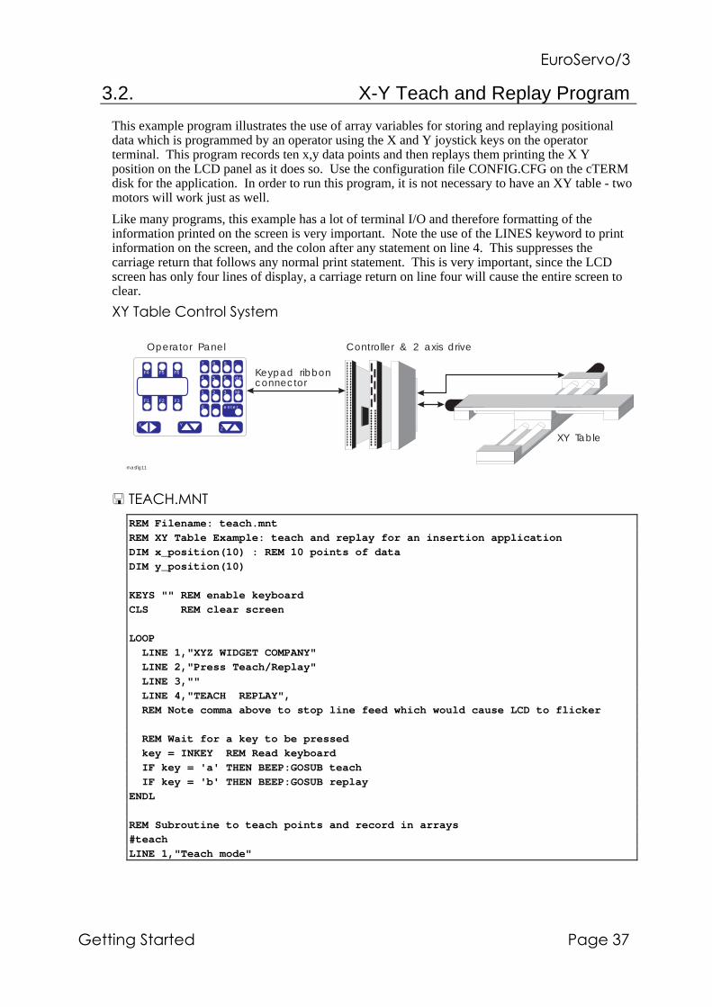
This example program illustrates the use of array variables for storing and replaying positionaldata which is programmed by an operator using the X and Y joystick keys on the operatorterminal. This program records ten x,y data points and then replays them printing the X Yposition on the LCD panel as it does so. Use the configuration file CONFIG.CFG on the cTERMdisk for the application. In order to run this program, it is not necessary to have an XY table - twomotors will work just as well.
Like many programs, this example has a lot of terminal I/O and therefore formatting of theinformation printed on the screen is very important. Note the use of the LINES keyword to printinformation on the screen, and the colon after any statement on line 4. This suppresses thecarriage return that follows any normal print statement. This is very important, since the LCDscreen has only four lines of display, a carriage return on line four will cause the entire screen toclear.
89��&*�����������������
Controller & 2 axis drive
XY Table
Operator Panel
F4 F5 F6
F1 F2 F3
XZ
Y
7 8 9 -
4 5 6 del
1 2 3 sp
0 . enter
Keypad ribbonconnector
masfig11
������:!/��
REM Filename: teach.mnt
REM XY Table Example: teach and replay for an insertion application
DIM x_position(10) : REM 10 points of data
DIM y_position(10)
KEYS "" REM enable keyboard
CLS REM clear screen
LOOP
LINE 1,"XYZ WIDGET COMPANY"
LINE 2,"Press Teach/Replay"
LINE 3,""
LINE 4,"TEACH REPLAY",
REM Note comma above to stop line feed which would cause LCD to flicker
REM Wait for a key to be pressed
key = INKEY REM Read keyboard
IF key = 'a' THEN BEEP:GOSUB teach
IF key = 'b' THEN BEEP:GOSUB replay
ENDL
REM Subroutine to teach points and record in arrays
#teach
LINE 1,"Teach mode"

�#�����"�$%
'&���%� ����������&����
LINE 4,"RECORD",REM record 10 points of data
FOR point = 1 to 10
LINE 2,"Move to posn: ",point,
REPEAT REM repeat jog motors until record button F1 is pressed
REM motor X
IF READKEY = 'x' DO
JOG[0] = 30 REM 30 mm/s
ELSE IF READKEY = 'u' DO
JOG[0] = -30
ELSE
STOP[0] REM key released - stop motor
ENDIF
ENDIF
REM motor Y
IF READKEY = 'y' DO
JOG[1] = 30 REM 30 mm/s
ELSE IF READKEY = 'v' DO
JOG[1] = -30
ELSE
STOP[1] REM key released - stop motor
ENDIF
ENDIF
REM print X,Y positions on line 3
LINE 3,"X",POS[0] USING 4;"Y",POS[1] USING 4
UNTIL INKEY = 'a'
BEEP
x_position(point) = POS[0] REM Read position of X axis
y_position(point) = POS[1] REM Read position of Y axis
NEXT REM get next point
RETURN

�#�����"�$%
����������&���� '&���%�
REM Replay learnt points
#replay
LINE 1,"Replay mode"
LINE 4,"STOP",
FOR point = 1 TO 10
VECTORA = x_position(point), y_position(point)
GO
REM If stop key pressed then exit
IF INKEY = 'a' THEN STOP[0,1]:EXIT
REM print X,Y positions on line 3
LINE 3,"X",POS[0] USING 4;"Y",POS[1] USING 4
NEXT
RETURN
This program uses the READKEY function to jog the motors X and Y back and forth in responseto pressure on the operator panel X and Y keys. It is relatively easy however to adapt the programto work with a standard potentiometer joystick connected to the analogue inputs. The analogueinputs return a 10 bit value 0 - 1024 between -10V and +10V (or 0-5V). The best way to connectthe joystick is to connect +/-12V across the potentiometer and connect the wiper to the analogueinputs 1+ and 2+. The differential inputs 1- and 2- should be connected to analogue ground.
The analogue inputs, read by the keywords ANALOGUE1 and ANALOGUE2 (abbreviated A1and A2), will return 0 when the joystick is in the fully negative position and 1024 when in thefully positive. A value of 512 will be returned when the joystick is central. Most joysticks areequipped with trimmers to adjust the zero position, but electrical noise can cause some jitter about0V, so it is good practice to put a deadband of 10 counts around the zero point.
The following code fragment illustrates the implementation of analogue joystick control, whichwould replace the REPEAT ..UNTIL loop in TEACH.MNT:
REPEAT REM repeat until record button F1 is pressed
REM jog at X,Y speed given by analogue inputs, range ..
REM is 0-1024, subtract 512 to give bi-directional control
jog_x = A1-512
jog_y = A2-512
REM deadband of 10 points either side of zero
IF ABS(jog_x) < 10 THEN jog_x = 0
IF ABS(jog_y) < 10 THEN jog_y = 0
JOG = jog_x, jog_y
UNTIL INKEY = 'a'
STOP[0,1] REM stop jog motion
Note this example provides variable speed movement on the table depending on the position of thejoystick, and also allows simultaneous movement on X and Y, which is not possible using theoperator panel.
Another feature that would be worthwhile adding to the teach program is to datum the axes onpower-up of the system. This can be achieved by using limit switches on the table and the HOMEkeyword, further details of this are given in the MINT PROGRAMMING GUIDE.

�#�����"�$%
'&���)2 ����������&����
3.3. Software Gearbox Example - Coil Winding Machine
The controller has a 'software gearbox' function that makes it ideal for controlling machines thathave to follow a master encoder or pulse train. A typical requirement is to wind wire onto a drumwhich rotates at a speed dictated by a mechanical drive from a wire drawing machine. When thespool is empty, the spool rotates at the highest speed, slowing down as layers of wire are woundonto the spool. The thickness of wire, width of the spool, and spacing between each wire must bechanged to cope with different thickness of product.
An encoder on the spool rotation provides a speed signal which the controller uses as a referencefor a servo motor which drives the spool back and forth via a lead screw.
Encoders can be incremental or multi-turn absolute types. Multi-turn absolute encoders are moreexpensive than incremental, but always indicate the absolute position of the axis. In the spoolerexample, there is no real advantage in using an absolute encoder to measure spool rotation, but ifthe servo motor is fitted with an absolute encoder then it is not necessary to datum the unit onpower-up. This is an important feature when recovering from a power failure, since it allows themachine to re-start with a part full spool.
An operator terminal on the front of the machine allows the operator to change the following ratio(spacing between wires) and the position of left and right end of travel.
�����&���&��#���0������;�������/&(����
Controller/drive
Main spooldrive
Traverse driveservomotor/encoder
Spoolencoder
Leadscrew
From wire drawingmachine
Optional communications link tohost computer
Operator Panel
F4 F5 F6
F1 F2 F3
XZ
Y
7 8 9 -
4 5 6 del
1 2 3 sp
0 . enter
masfig10

�#�����"�$%
����������&���� '&���)�
The example MINT program uses the standard operator panel with it's six function keys whichreturn a,b,c,d,e and f, plus numeric and enter keys. This example however does not takeadvantage of the 'soft-key' approach used in previous examples (this program is not included onthe cTERM disk).
REM Filename SPOOLER.MNT
REM Example program for stand alone spooler
REM defaults
AXES[0]
ratio = 1 REM 1:1 gearbox ratio
SCALE = 1000 REM 1000 counts on servo encoder = 1mm of travel
left_limit = 10
right_limit = 210
REM perform zero datum on limit switch (negative direction)
HOME = _neg
REM infinite loop to provide operator display
LOOP
CLS : REM clear operator panel display
PRINT "XYZ Ltd Spooler"
PRINT "Press:"
PRINT "F1 to start"
PRINT "F2 enter parameters"
REPEAT
key = INKEY : REM read keyboard buffer
UNTIL key = 'a' OR key = 'b'
IF key = 'a' THEN GOSUB spool
IF key = 'b' THEN GOSUB enter_parameters
ENDL
#spool : REM subroutine to perform spooling
CLS
PRINT "XYZ Ltd Spooler"
PRINT "Spooler running"
PRINT "Press F3 to stop"
REPEAT
REM forward direction
FOLLOW = ratio
PAUSE POS > right_limit
REM reverse direction
FOLLOW = -ratio
PAUSE POS < left_limit
UNTIL INKEY = 'c' : REM stop function key pressed
STOP
RETURN
#enter_parameters : REM subroutine to change left, right limits and ratio
CLS
INPUT "Left limit",left_limit
INPUT "Right limit",right_limit
INPUT "Ratio",ratio
RETURN

�#�����"�$%
'&���) ����������&����
3.3.1. Program Narrative
The variable ratio is used to store the 'software gearbox' ratio, i.e. the number of servo motorencoder pulses moved per pulse from the spool encoder. This ratio is variable anywhere between-127 and +127, in increments of 0.003.
left_limit and right_limit store the limits of linear travel. In this example, there are 4000 quadratureencoder counts per revolution of the servo motor encoder and a 4mm pitch lead screw. Therefore,setting the keyword SCALE to 1000 means that the limit positions may be expressed in mm.
This program is a simple example of a spooler with operator panel. A typical enhancement onpractical machines is a dwell on reversal to allow the material to ride up onto the new layer.
3.3.2. Remote Operation Using the COMMS array
In many applications the spooler system may be required to be adjusted remotely, underinstruction of a host computer and perhaps whilst the spooling operation is in progress. Thecontroller's protected communications protocol allows data to be exchanged between a hostcomputer and the controller by means of a 100 location array called COMMS. COMMS workslike a letterbox, the host computer can write to and read the value of specific locations, over theserial port, for use by the controller program. This happens automatically, without any overheadin the MINT program itself.
For remote operation, the variables ratio, left_limit and right_limit would be replaced by threeCOMMS letterbox addresses:
REM routine to perform spooling
LOOP
REM forward direction
FOLLOW = COMMS(1) : REM COMMS(1) = ratio
PAUSE POS > COMMS(2) : REM COMMS(2) = right limit
REM reverse direction
FOLLOW = -COMMS(1)
PAUSE POS < COMMS(3) : REM COMMS(3) = left limit
ENDL
If a value is changed by the host computer, this automatically appears in the program whilst it isrunning. A protected protocol is used to make the system fault tolerant. This protocol is ANSI3.28 based, compatible with many other manufacturers of drive systems. The structure andimplementation of protected communications is discussed in detail in the MINT ProgrammingGuide and the APPLICATIONS AND UTILITIES DISKETTE manual, which covers the use ofcTERM for reading and writing to the controller using protected communications.

�#�����"�$%
����������&���� '&���)%
3.4. Infeed Packaging Machine
MINT offers a number of features to facilitate the control of product that is continuously movingon a production line. A popular application in this area is Infeed machines, where the requirementis to put irregularly spaced product into pockets on a conveyor, so that they may be fed into adownstream machine.
The creation of 'order from disorder' is a taxing application of the controller, but has a largeapplication base in the food, domestic product and pharmaceutical industry.
The following explains a simple Infeed system and the use of the OFFSET keyword.
The Infeed machine accepts irregularly spaced products on an input conveyor and feeds theproduct accurately into flights (pockets on a conveyor) on a Parent machine, typically a packagingmachine that inserts product into boxes.
Product is fed onto the Stripping Conveyor, which runs slightly faster than the Input conveyor toseparate product. Product is next transferred to the Synchronising Conveyor, which runs at thesame base speed as the Parent machine, determined by following a pulse train generated by anEncoder (the Parent Machine Encoder). This Encoder is geared to the Parent machine such thatone turn (1000 pulses) corresponds to one flight spacing. The encoder output is fed into the pulseinput on the controller. The number of pulses per revolution is assigned to the MINT variable,WRAP.
When a product passes the Photocell, the controller reads the position of the flight and calculatesa correction on the belt to feed product accurately into a flight. The correction is expressed as apositional error in the product with respect to the flight position. The MINT OFFSET commandis used to perform the correction. OFFSET works much like a normal relative positional move,except that the acceleration-deceleration profile is imposed on the base speed of the Parentmachine.
In order to achieve high throughput, the offset acceleration and deceleration must be performed asquickly as possible. This can result in the product slipping on the belt and thus introducing afurther positional error which means that it is not accurately synchronised with the flights.Problems with products slipping have been reduced by using 'S' shaped smoothed acceleration-deceleration profiles.
In practice it is often possible to have two products on the synchronising conveyor at one time,therefore the program has been written so that it can simultaneously sense and correct productposition. The program also ensures that the second correction is not implemented until the firstpackage is fed into the Parent machine.
A further function of the controller is to provide machine status information to the operator, suchas number of products per hour etc. This information can be displayed on the operator terminal, asingle line LCD display and keypad, which is panel mounted on a convenient part of the machine.The operator terminal is also used to enter set up information, for instance product length and thespeed of the metering conveyor.
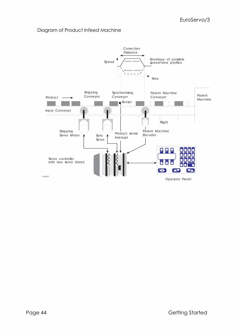
�#�����"�$%
'&���)) ����������&����
�&��&���0�'���#(����0����/&(����
StrippingServo Motor Sync
Servo
Input Conveyor
StrippingConveyor
SynchronisingConveyor
Time
Speed
CorrectionDistance
ProductParent MachineConveyor
Flight
Sensor
ParentMachine
Product senseInterrupt
Parent MachineEncoder
Operator Panel
F4 F5 F6
F1 F2 F3
XZ
Y
7 8 9 -
4 5 6 del
1 2 3 sp
0 . enter
Servo controllerwith two servo drives
Envelope of possiblespeed/time profilesForward correction
Backward correction
masfig12
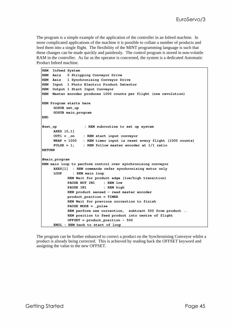
�#�����"�$%
����������&���� '&���),
The program is a simple example of the application of the controller in an Infeed machine. Inmore complicated applications of the machine it is possible to collate a number of products andfeed them into a single flight. The flexibility of the MINT programming language is such thatthese changes can be made quickly and painlessly. The control program is stored in non-volatileRAM in the controller. As far as the operator is concerned, the system is a dedicated AutomaticProduct Infeed machine.
REM Infeed System
REM Axis 0 Stripping Conveyor Drive
REM Axis 1 Synchronising Conveyor Drive
REM Input 1 Photo Electric Product Detector
REM Output 1 Start Input Conveyor
REM Master encoder produces 1000 counts per flight (one revolution)
REM Program starts here
GOSUB set_up
GOSUB main_program
END
#set_up : REM subroutine to set up system
AXES [0,1]
OUT1 = _on : REM start input conveyor
WRAP = 1000 : REM timer input is reset every flight (1000 counts)
PULSE = 1; : REM follow master encoder at 1/1 ratio
RETURN
#main_program
REM main loop to perform control over synchronising conveyor
AXES[1] : REM commands refer synchronising motor only
LOOP : REM main loop
REM Wait for product edge (low/high transition)
PAUSE NOT IN1 : REM low
PAUSE IN1 : REM high
REM product sensed - read master encoder
product_position = TIMER
REM Wait for previous correction to finish
PAUSE MODE = _pulse
REM perform new correction, subtract 500 from product ..
REM position to feed product into centre of flight
OFFSET = product_position - 500
ENDL : REM back to start of loop
The program can be further enhanced to correct a product on the Synchronising Conveyor whilst aproduct is already being corrected. This is achieved by reading back the OFFSET keyword andassigning the value to the new OFFSET.

�#�����"�$%
'&���)- ����������&����
4. Trouble Shooting Guide
Symptom CheckStatus display blank andcontroller not functioning.
Check power supply, +5V,+12V and -12V is connected and switchedon.
Status display shows 'S' Check stop switch input is correctly wired and has power applied
Status display shows 'L' Check limit switch input is correctly wired has power applied
Status display shows 'L' andwiring to switches is o.k.
Check that opto-isolator supply (UP) is connected.
Status display shows an '8.' andcontroller does not communicateover serial port.
Check that the 5V supply is at least 4.9V (controller is held in reset).
Cannot communicate withcontroller over RS232 port(cannot get "P>" or "C>" promptby pressing return.
Verify that the terminal emulator program is loaded and set-up correctly.Check that the terminal emulator program is configured for the correctserial port (COM1 or COM2) and that the lead is plugged in both ends.Check wiring for RS232 lead.Check that +/-12V is supplied to the controller.Check that there is not a program ready running on the controller (typeCntl-E to abort the program).Check that the controller card is not an RS485 model (model number oncard should not end in "/4").Check that card address switch is set correctly (normally 0000).
Controller appears to be powered-up and working but will not causemotors to turn over.
Check that the connections between motor and controller are correct.(Type "TQ[0,1,2] = 100;" to set all axis numbers to +10V and verifythat this voltage appears on the demand input to the amplifier -remember to ensure that the motors will not cause any physical damagewhen doing this).Ensure that the amplifier is enabled and working when the controller isnot in error. (When the controller is first powered up the amplifiersshould be disabled if there is no program loaded for automatic execution(there is often an LED on the front of the amplifier to indicate status).Typing "RESET" at the "C>" prompt should cause the amplifiers to beenabled.)Check that configuration file is loaded into controller and has beenRUN, or that the servo loop gains are correctly set-up. (Type "PRINTGN" to verify that the controller proportional gain is no zero and refer toservo-system set-up).

�#�����"�$%
����������&���� '&���).
Symptom CheckMotor runs off uncontrollablywhen controller is switched on(Status display shows an '8').
Check that encoders are connected to controller and are functioningcorrectly. (Use a dual trace oscilloscope to display both channels of theencoder simultaneously).Check that amplifiers are connected correctly to controller and that withzero demand there is 0V at the amplifier demand input. (Type"SO[0,1,2]" to set all demand outputs to 0V and verify that this voltageappears at the output from the controller. A voltage of +10V or -10Vindicates that the controller analogue output is damaged.)Verify that amplifiers are correctly set-up and that the motor does notmove with 0V on the demand input.Verify that the controller and amplifier are correctly grounded to acommon earth point.
Motor runs off uncontrollablywhen controller is switched onand servo loop gains are appliedor a when move is set in progress,motor then stops after a short timeand status display shows an 'F'.
Check that encoder 0 and demand 0 "D0" are connected to the sameaxes of motion; repeat for axis 1 and 2.Check amplifier connection is correct with respect to polarity ofamplifier demand. (Try swapping the +demand and -demandconnections to the amplifier; note: this is not possible with someamplifiers due to ground reference problems in which case you need toswap the encoder channels A and B.)Check maximum following error is set to a reasonable value. (Findicates maximum following error exceeded; for setting up themaximum following error should be set to a high value. Type"MF[0,1,2] = 16000;" to set all axes to maximum following error of16000 encoder counts.)
Motor is under control, butvibrates or overshoots during amove.
Servo loop gains may be set too high. (Go throughout the servo systemset-up procedure to establish correct gains.)
Motor is under control, but whenmoved to a position and back tostart does not return to the sameposition.
Check that the encoders channels A and B are clean signals and thatthey are correctly wired to the controller. (Use a dual trace oscilloscopeto display both channels of the encoder at the controller back plane.Verify that when the motor turns, the two square wave signals are 90degrees out of phase.)Check that the encoder signal is free from electrical noise. (Use theoscilloscope as above - verify that the complimentary outputs on theencoder (if fitted) are correctly wired.If single ended encoders are fitted to the motors and the signals arenoisy, try re-routing the encoder cables to avoid any source of electricalnoise (notably the motor power leads). If this fails, the only solutionmay be to fit encoders with differential line driver outputs.Ensure that the encoder leads use screened cable and that the screen isattached to the screen connection on the encoder plug at the controllerend only.)Verify that the controller and amplifier are correctly grounded to acommon earth point.


i7/98
MINT™ Programming Guide
For: SmartMoveSmartStepEuroSystemEuroServoEuroStep
MN1260

ii 7/98
Copyright Optimized Control Ltd 1988-97.
All rights reserved.
This manual is copyrighted and all rights are reserved. This document may not,inwhole or in part,be copied or reproduced in any form without the prior writtenconsent of Baldor Optimized Control.
Baldor Optimized Control makes no representations or warranties with respect tothe contents hereof and specifically disclaims any implied warranties of fitness forany particular purpose. The information in this document is subject to changewithout notice. Baldor Optimized Control assumes no responsibility for any errorsthat may appear in this document.
MINT™ is a registered trademark of Baldor Optimized Control Ltd.
Baldor Optimized Control Ltd178-180 Hotwell RoadBristolBS8 4RPU.K.
Baldor Electric CompanyTelephone: +1 501 646 4711Fax: +1 501 648 5792email: [email protected]
Telephone: +44 (0)117 987 3100Fax: +44 (0)117 987 3101email: [email protected] site: www.baldor.co.uk
Baldor ASR GmbHTelephone: +49 (0)89 90508-0Fax: +49 (0)89 90508-492
Baldor ASR AGTelephone: +41 (0)52 647 4700Fax: +41 (0)52 659 2394
Australian Baldor Pty LtdTelephone: +61 2 9674 5455Fax: +61 2 9674 2495
Baldor Electric (F.E.) Pte LtdTelephone: +65 744 2572Fax: +65 747 1708
MN1260

iii7/98
Technical Support
When asking for technical support regarding software, please make sure you have thefollowing information available:
• The controller name.
• RS232 or RS485 serial communications used.
• Version of MINT. This can be found by typing VER at the command line or byreading the EPROM label.
MN1260

SCALE/SF
Purpose:
To set all encoder/step driven variables (e.g. SPEED, POS) to user defined units.
Format:SCALE[axes] = <expr> {,<expr> ...}v = SCALE[axis]
Abbr. Read Write Command Multi-Axis Scaled Default Range
SF ❑ ❑ ❑ ❑ 1 1 to 32000
Firmware Version Motor Type
Process MINT Interpolation MINT/3.28 Servo Stepper
❑ ❑ ❑ ❑ ❑
Controller
ES/D ES/S ES/M3 SMS/1 SMS/2 SMS/3 SMM/1 SMM/2 SMM/3 SST/3 ESTE/D ESTE/S
❑ ❑ ❑ ❑ ❑ ❑ ❑ ❑ ❑ ❑ ❑ ❑
...
iv 7/98
Preface
This manual describes how to use the MINT™ motion programming language for theservo and stepper positioning controllers. Rudimentary knowledge of the Basicprogramming language is recommended, but not absolutely necessary before reading thistext.
Some of the programs listed are available on the Applications and Utilities Diskette. Thefile name will be given above the listing along with a disk icon !.
Keywords are shown with the following format. For example:
MN1260
v7/98
Where the following rules apply:
• Many keywords accept an abbreviation. This is shown by full/abbreviated, forexample SCALE/SF where SCALE is the full keyword and SF its abbreviation.
• Words in capital letters are keywords (for example SCALE above) and must be enteredas shown, except that they can be entered in any combination of upper and lowercase.
For example:
scale = 10Scale = 20
SCALE = 30
• You are asked to supply any items shown in lower case letters between angledbrackets. Where the term <expression> or <condition> is used, this refers to avariable, constant or other valid numeric expression. For example:
a * b / c
a
POS < 100
• Items in curly brackets { } are optional. For the example above:
SCALE[axes] = <expr> {,<expr> ...}
the following are all valid syntax:
SCALE = 1
SCALE = 10,10SCALE[0,1,2] = 20,30,40
SCALE.1 = 100
The dots “...” signify that more expressions or statements can follow.
• [axes] can be replaced by any valid axis string. For example:
SCALE[1] = 10
SCALE[0,1] = 10,20SCALE = 10,20
SCALE.2 = 100
• All punctuation except curly brackets must be included as shown.
• Sections of code are expressed as shown. They would normally be entered into aprogram and executed.
SPEED.1 = 100
MOVEA.1 = 200
GO.1
MN1260

vi 7/98MN1260
The table shows various attributes of the keyword:
Abbr Keyword abbreviation.
Read If the keyword is readable.
Write If the keyword is writable.
Command If the keyword is a command.
Multi-axis If the keyword applies to more than one axis.
Scaled If the values written to or read from the keyword are scaled by thescaling factor SCALE.
Default Default value for a writable variable
Range Numeric range of the keyword. Please note this range is given for aSCALE factor of 1 only. If the number is followed by .0, this impliesthat the keyword will accept fractional numbers.
Process MINT Process MINT firmware option supporting cam profiling, flyingshears and extended software gearboxes.
Interpolation Interpolation MINT firmware option supporting circular interpolation
MINT/3.28 Host controlled firmware option.
Servo Keyword applies to a servo axis
Stepper Keyword applies to a stepper axis
ES/D EuroSystem: 2 axis servo/3 axis stepper
ES/S EuroStep: 3 axis stepper
ES/M3 EuroServo: 3 axis servo
SMM/1 SmartMove/1; bookcase format 1 axis servo controller
SMM/2 SmartMove/2; bookcase format 2 axis servo controller
SMM/3 SmartMove/3; bookcase format 3 axis servo controller
SMS/1 SmartSystem/1: 1 axis servo boxed unit
SMS/2 SmartSystem/2: 2 axis servo boxed unit
SMS/3 SmartSystem/3: 3 axis servo boxed unit
SST/3 SmartStep: 3 axis stepper with integral drives
ESTE/D EuroSystem/STE: 2 axis servo/3 axis stepper STE controller
ESTE/S EuroStep/STE: 3 axis STE controller

vii7/98
SmartMove ControllersSmartMove is a new addition to the manual. Where it is not represented in the controllertable, it should be considered to be functionally equivalent to SmartSystem/3.
Stepper Only ControllersStepper only controllers use a subset of the MINT™ Programming Language. Allreferences to servo systems will be marked and should be ignored.
Related ManualsRefer to Manuals and Software for MINT Products on page 15-1.
Updates from Issue 11 to Issue 12The MINT Programming Manual has been updated to include a number of new keywordswhich have been introduced into esMINT v2.65 and above. At the time of writing, theversion of MINT is esMINT v2.71.
• esMINT v2.71 and above supports an OFFSET move on a FLY move.
• A deceleration parameter using the new DECEL keyword can be applied to apositional move or JOG. Both the acceleration and deceleration can now also bechanged on the fly. In order to maintain backwards compatibility, the decelerationterm must be ‘switched on’ using the new AXISCON keyword.
• The new FASTENC keyword latches the ENCODER position on a fast interrupt. Thiscan be useful in situations where the position of a rotary knife, for example, isrequired.
• Data capture routines are used to capture data such as following error and axisvelocity for display on a software oscilloscope. The data capture routine are used toassist in servo tuning. cTERM for Windows provides a graphing option to exploit thisfeature.
• A new expression parser has been incorporated giving a 10-15% speed improvementin the execution of expressions.
MN1260

viii 7/98
• The XENCODER keyword is supported as standard within the firmware (denoted bythe /X on the version number). In order to use the three channel encoder interfaceboard, the AXISCON keyword must be used to ‘switch’ it on. The 3 channel encoderboard can now be used as a master reference for cams and flying shears.
• In order to maximize the use of the memory card, array data can be stored off-line onthe memory card. This is given by the use of the new OFFLINE keyword. From thenon, the array is used in the same way as any other arrays stored locally in memory.
• The FOLLOW keyword is now able to follow the pulse timer input using theFOLLOWAXIS keyword. This allows position lock on the pulse input.
• The new BAUD keyword can be used to change the serial baud to any value between300 and 19,200. By default the controller powers up at 9600 baud.
• The ECHO keyword can be used to remove command line echo and error messages.
• The new TRIGGER keyword can be used to trigger moves off any of the 8 digitalinputs.
• A clutch distance can be defined for FOLLOW on axes 0 and 1. This is achieved bysetting a master increment distance using the MASTERINC keyword.
• The error handling capability of MINT has been extended with the introduction of theERR keywords. System run time errors such as “Out of Range” or “Motion inProgress” can be trapped within the #ONERROR routine.
• Torque mode (see TORQUE keyword) and JOG can be entered while motion is inprogress on the axis, without a “Motion in Progress” error resulting:
move type ( TORQUE
move type ( JOG
• It is now possible to switch between JOG and FOLLOW without a “Motion inProgress” error resulting:
JOG ( FOLLOW ( JOG ( FOLLOW
• Maximum following error detection can be turned off with the AXISCON keyword.
• Maximum following error (MFOLERR) has been increased from 16000 counts to32767 counts.
• A move can be cancelled on a stop input by using the STOPMODE keyword.
• The PRESCALE keyword allows the encoder input to be scaled down. Useful forwhere a high resolution encoder cannot be changed but greater absolute distance isrequired.
• GO will no longer issue “Motion in Progress” errors unnecessarily.
MN1260

ix7/98
Understanding MINT Version NumbersFirmware versions are given a name (eg MINT) followed by the core version number andany options. The standard options are:
/4 Multi-drop 485
/S Stepper only
/3 EuroServo/3
/SMMx SmartMove/x/SMSx SmartSystem/x
/KCxx Processor type followed by clock speed - 12 or 14 MHz.KC16 is assumed to be standard and is not used.
-Jxxx Job number. Used to reference customized firmware.
If the version number is post-fixed with a letter (a, b, c etc), for example 2.53d, thisdictates a minor bug fix to the software or a minor revision to a keyword.
A post-fix of “.bX”, for example v2.52.b2, is used to reference beta release version ofthe software. In this case beta release 2 of version 2.52.
The following sections describe the version numbering system for MINT and MINT/3.28.HPGL conforms to the numbering system above.
Interpolation/Process MINT: cMINT pre v2.65Typing VER at the command line will return the version number.
c3MINT v2.53 /KC-12 /S /3 /4 /f /P /M /Xe /L /STE -J<no>| | | | | | | | | | | | | | || | | | | | | | | | | | | | job no for custom firmware
| | | | | | | | | | | | | STE controller
| | | | | | | | | | | | Laser modulation (ES/3 or SMS/3 only)
| | | | | | | | | | | External encoder interface
| | | | | | | | | | Memory card; A denotes auto boot from card
| | | | | | | | | | X denotes memory expansion
| | | | | | | | | Process MINT
| | | | | | | | FASTPOS implemented (standard in v2.53+)
| | | | | | | RS485 protocol
| | | | | | EuroServo/3 or SmartSystem/3
| | | | | stepper only (EuroStep)
| | | | Processor clock speed (if not 16MHz standard)
| | | KC processor (if not 16MHz standard)
| | minor (revision) release number
| major release number
number of axes supported on card
MN1260
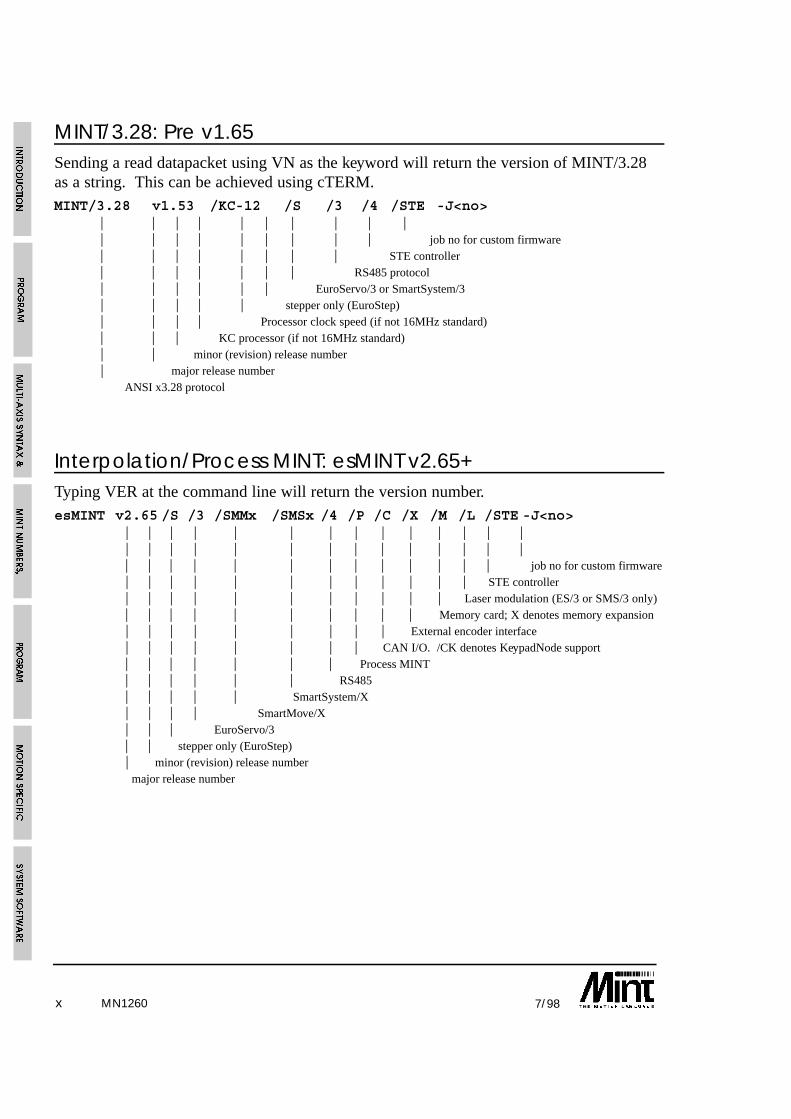
x 7/98
MINT/3.28: Pre v1.65Sending a read datapacket using VN as the keyword will return the version of MINT/3.28as a string. This can be achieved using cTERM.MINT/3.28 v1.53 /KC-12 /S /3 /4 /STE -J<no>
| | | | | | | | | || | | | | | | | | job no for custom firmware| | | | | | | | STE controller| | | | | | | RS485 protocol| | | | | | EuroServo/3 or SmartSystem/3| | | | | stepper only (EuroStep)| | | | Processor clock speed (if not 16MHz standard)| | | KC processor (if not 16MHz standard)| | minor (revision) release number | major release number
ANSI x3.28 protocol
Interpolation/Process MINT: esMINT v2.65+Typing VER at the command line will return the version number.esMINT v2.65 /S /3 /SMMx /SMSx /4 /P /C /X /M /L /STE -J<no>
| | | | | | | | | | | | | || | | | | | | | | | | | | || | | | | | | | | | | | | job no for custom firmware| | | | | | | | | | | | STE controller| | | | | | | | | | | Laser modulation (ES/3 or SMS/3 only)| | | | | | | | | | Memory card; X denotes memory expansion| | | | | | | | | External encoder interface| | | | | | | | CAN I/O. /CK denotes KeypadNode support| | | | | | | Process MINT| | | | | | RS485| | | | | SmartSystem/X| | | | SmartMove/X| | | EuroServo/3| | stepper only (EuroStep)| minor (revision) release number
major release number
MN1260

xi7/98
MINT/3.28: v1.65+Sending a read datapacket using VN as the keyword will return the version of MINT/3.28as a string. This can be achieved using cTERM.MINT/3.28 v1.65 /S /3 /SMMx /SMSx /4 /X /STE -J<no>
| | | | | | | | | | || | | | | | | | | | || | | | | | | | | | job no for custom firmware| | | | | | | | | STE controller| | | | | | | | External encoder interface| | | | | | | RS485 protocol| | | | | | SmartSystem/X| | | | | SmartMove/X| | | | EuroServo/3| | | stepper only (EuroStep)| | minor (revision) release number| major release number
ANSI x3.28 protocol
Standard Options in Detail/S - Stepper
Standard for EuroStep and SmartStep/3.
Stepper only support for the axes. /S implies that there is no support for servo motors.
/4 - RS485
Multi-drop RS485 is supported allowing up to 16 controllers to be connected to a singlehost. Two communication methods are supported based around ANSI/3.28. The MINTComms Protocol is standard within the MINT interpreter and can be used for data transferto an executing program. MINT/3.28 is a firmware variant which allows immediatecommand execution.
If /4 is not given, RS232 support is default.
/P - Process
Standard for all servo controllers. Interpolation MINT is standard on all controllerssupporting steppers.
Allows sophisticated software gearing functions such as cam profiling and flying shears.If /P is not given, then interpolation MINT is standard which supports circularinterpolation.
Process MINT is not supported on stepper axes.
MN1260

xii 7/98
/C - CAN
CAN bus I/O supported. This applies only to SmartMove, but when fitted allowsSmartMove to drive the ioNODE range of CAN based I/O devices. /C results in a loss of1000 bytes from the program space reducing it to 26K.
If the CAN keypad (KeypadNode) is supported, this is denoted by a K following the C(/CK).
/X - Three Channel Encoder Interface
Standard for all 2 and 3 axis controllers with the exception of EuroSystem andEuroSystem/STE.
If given, supports the Three Channel Encoder Interface board. This device gives threeadditional encoder input channels which can be used as master references for softwaregearboxes, cam profiling and flying shears.
/M - Memory Card
Standard unless /MX is requested.
Allows the program and configuration file to be stored on battery backed S-RAM,independent of the controller memory. /M also allows array data to be expanded bystoring the arrays on the memory card.
/MX - Memory Expansion
The program and configuration files are stored on an external battery backed memorycard, thus leaving the controller memory free for compiled code and array data. /MXallows larger programs to be written than can be normally supported in the standardonboard RAM.
MN1260

xiii7/98
1. Introduction . . . . . . . . . . . . . . . . . . . . . . . . . . . . . . . . . . . . . . . . . . . . . . . . . . 1-1
1.1 MINT Basics . . . . . . . . . . . . . . . . . . . . . . . . . . . . . . . . . . . . . . . . . . . . . . . 1-5
1.1.1 Program Execution and Termination . . . . . . . . . . . . . . . . . . . . . . . . 1-6
1.2 Safety Features . . . . . . . . . . . . . . . . . . . . . . . . . . . . . . . . . . . . . . . . . . . . . 1-6
1.3 MINT Versions . . . . . . . . . . . . . . . . . . . . . . . . . . . . . . . . . . . . . . . . . . . . . 1-7
1.4 Systems with more than Three Axes (multi-drop) . . . . . . . . . . . . . . . . . . . 1-7
2. Program Structure . . . . . . . . . . . . . . . . . . . . . . . . . . . . . . . . . . . . . . . . . . . 2-1
3. Multi-axis Syntax and Motion K eywords . . . . . . . . . . . . . . . . . . . . . . 3-1
3.1 Motion Commands . . . . . . . . . . . . . . . . . . . . . . . . . . . . . . . . . . . . . . . . . . 3-1
3.2 Motion Variables . . . . . . . . . . . . . . . . . . . . . . . . . . . . . . . . . . . . . . . . . . . . 3-1
3.3 Multi-Axis Syntax . . . . . . . . . . . . . . . . . . . . . . . . . . . . . . . . . . . . . . . . . . . 3-2
3.3.1 Single Axis References using Dot . . . . . . . . . . . . . . . . . . . . . . . . . . 3-5
4. MINT Numbers, Variables and Operators . . . . . . . . . . . . . . . . . . . . . 4-1
4.1 Numbers . . . . . . . . . . . . . . . . . . . . . . . . . . . . . . . . . . . . . . . . . . . . . . . . . . 4-1
4.2 Binary Numbers . . . . . . . . . . . . . . . . . . . . . . . . . . . . . . . . . . . . . . . . . . . . 4-1
4.3 Constants . . . . . . . . . . . . . . . . . . . . . . . . . . . . . . . . . . . . . . . . . . . . . . . . . . 4-2
4.3.1 Pre-defined Constant Keywords . . . . . . . . . . . . . . . . . . . . . . . . . . . 4-3
4.4 Variables . . . . . . . . . . . . . . . . . . . . . . . . . . . . . . . . . . . . . . . . . . . . . . . . . . 4-5
4.4.1 Non-volatile Variables . . . . . . . . . . . . . . . . . . . . . . . . . . . . . . . . . . 4-6
4.5 Arrays . . . . . . . . . . . . . . . . . . . . . . . . . . . . . . . . . . . . . . . . . . . . . . . . . . . . 4-8
4.5.1 Off-line Array Storage . . . . . . . . . . . . . . . . . . . . . . . . . . . . . . . . . . 4-10
4.5.2 Advanced use of Arrays . . . . . . . . . . . . . . . . . . . . . . . . . . . . . . . . . 4-12
4.5.3 Array Data File Format . . . . . . . . . . . . . . . . . . . . . . . . . . . . . . . . . 4-14
4.5.4 Uploading and Downloading Array Data . . . . . . . . . . . . . . . . . . . . 4-17
4.6 Relational and Mathematical Operators . . . . . . . . . . . . . . . . . . . . . . . . . . . 4-20
4.6.1 Performing Bitwise Operations . . . . . . . . . . . . . . . . . . . . . . . . . . . . 4-21
4.6.2 Trigonometric Functions . . . . . . . . . . . . . . . . . . . . . . . . . . . . . . . . 4-22
MN1260
Table of Contents
xiv 7/98
5. Program Control . . . . . . . . . . . . . . . . . . . . . . . . . . . . . . . . . . . . . . . . . . . . . 5-1
5.1 Conditional Statements . . . . . . . . . . . . . . . . . . . . . . . . . . . . . . . . . . . . . . 5-1
5.1.1 IF .. THEN statement . . . . . . . . . . . . . . . . . . . . . . . . . . . . . . . . . . . 5-1
5.1.2 IF block structure . . . . . . . . . . . . . . . . . . . . . . . . . . . . . . . . . . . . . . 5-1
5.1.3 PAUSE statement . . . . . . . . . . . . . . . . . . . . . . . . . . . . . . . . . . . . . . 5-3
5.2 Loops . . . . . . . . . . . . . . . . . . . . . . . . . . . . . . . . . . . . . . . . . . . . . . . . . . . . 5-4
5.2.1 FOR .. NEXT loop . . . . . . . . . . . . . . . . . . . . . . . . . . . . . . . . . . . . . 5-4
5.2.2 REPEAT .. UNTIL loop . . . . . . . . . . . . . . . . . . . . . . . . . . . . . . . . . 5-5
5.2.3 WHILE .. ENDW loop . . . . . . . . . . . . . . . . . . . . . . . . . . . . . . . . . . 5-5
5.2.4 LOOP .. ENDL loop . . . . . . . . . . . . . . . . . . . . . . . . . . . . . . . . . . . 5-6
5.2.5 EXIT statement . . . . . . . . . . . . . . . . . . . . . . . . . . . . . . . . . . . . . . . 5-7
5.2.6 Nesting . . . . . . . . . . . . . . . . . . . . . . . . . . . . . . . . . . . . . . . . . . . . . . 5-7
5.3 Subroutines . . . . . . . . . . . . . . . . . . . . . . . . . . . . . . . . . . . . . . . . . . . . . . . . 5-8
5.3.1 Events & Interrupts . . . . . . . . . . . . . . . . . . . . . . . . . . . . . . . . . . . . 5-9
5.3.1.1 Error Event: #ONERROR . . . . . . . . . . . . . . . . . . . . . . . . 5-10
5.3.1.2 Stop Input Interrupt: #STOP . . . . . . . . . . . . . . . . . . . . . . . 5-10
5.3.2 Digital Input Interrupt: #IN0 .. #IN7 . . . . . . . . . . . . . . . . . . . . . . . . 5-11
5.3.2.1 Position Latch Event: #FASTPOS . . . . . . . . . . . . . . . . . . 5-13
5.4 Terminal Input/Output . . . . . . . . . . . . . . . . . . . . . . . . . . . . . . . . . . . . . . . . 5-14
5.4.1 PRINT Statement . . . . . . . . . . . . . . . . . . . . . . . . . . . . . . . . . . . . . . 5-15
5.4.2 INPUT Statement . . . . . . . . . . . . . . . . . . . . . . . . . . . . . . . . . . . . . . 5-16
5.5 Keypad and Display . . . . . . . . . . . . . . . . . . . . . . . . . . . . . . . . . . . . . . . . . . 5-17
5.5.1 Programming the Keypad and Display . . . . . . . . . . . . . . . . . . . . . . 5-17
5.6 Sending Data to an Executing Program . . . . . . . . . . . . . . . . . . . . . . . . . . . 5-20
5.6.1 Serial Port/Keypad Buffer . . . . . . . . . . . . . . . . . . . . . . . . . . . . . . . 5-20
5.6.2 Reading Data from the Serial Buffer using INKEY . . . . . . . . . . . . 5-21
5.6.3 Host Computer Protected Protocol . . . . . . . . . . . . . . . . . . . . . . . . . 5-23
MN1260
xv7/98
6. Motion Specific Features . . . . . . . . . . . . . . . . . . . . . . . . . . . . . . . . . . . . 6-1
6.1 Torque Control . . . . . . . . . . . . . . . . . . . . . . . . . . . . . . . . . . . . . . . . . . . . . 6-1
6.2 Speed Control . . . . . . . . . . . . . . . . . . . . . . . . . . . . . . . . . . . . . . . . . . . . . . 6-2
6.3 Positional Control . . . . . . . . . . . . . . . . . . . . . . . . . . . . . . . . . . . . . . . . . . . 6-3
6.3.1 Linear Positional Control . . . . . . . . . . . . . . . . . . . . . . . . . . . . . . . . 6-3
6.3.2 Interpolated Moves . . . . . . . . . . . . . . . . . . . . . . . . . . . . . . . . . . . . . 6-5
6.3.3 Linear Interpolation . . . . . . . . . . . . . . . . . . . . . . . . . . . . . . . . . . . . 6-6
6.3.4 Circular Interpolation . . . . . . . . . . . . . . . . . . . . . . . . . . . . . . . . . . . 6-8
6.3.5 Velocity Profile . . . . . . . . . . . . . . . . . . . . . . . . . . . . . . . . . . . . . . . 6-9
6.3.6 Move Buffer and GO . . . . . . . . . . . . . . . . . . . . . . . . . . . . . . . . . . . 6-9
6.3.7 Contoured Moves . . . . . . . . . . . . . . . . . . . . . . . . . . . . . . . . . . . . . . 6-10
6.4 Establishing a Datum . . . . . . . . . . . . . . . . . . . . . . . . . . . . . . . . . . . . . . . . . 6-11
6.4.1 Home Control Word . . . . . . . . . . . . . . . . . . . . . . . . . . . . . . . . . . . . 6-12
6.4.2 Home Sequence . . . . . . . . . . . . . . . . . . . . . . . . . . . . . . . . . . . . . . 6-13
6.4.3 Order of Datuming . . . . . . . . . . . . . . . . . . . . . . . . . . . . . . . . . . . . . 6-14
6.4.4 Defining a New Position . . . . . . . . . . . . . . . . . . . . . . . . . . . . . . . . 6-15
6.5 Pulse Following . . . . . . . . . . . . . . . . . . . . . . . . . . . . . . . . . . . . . . . . . . . . . 6-15
6.6 Encoder Following/Software Gearbox . . . . . . . . . . . . . . . . . . . . . . . . . . . . 6-17
6.6.1 Clutch Distance . . . . . . . . . . . . . . . . . . . . . . . . . . . . . . . . . . . . . . . 6-18
6.6.2 High Resolution Software Gearboxes . . . . . . . . . . . . . . . . . . . . . . . 6-19
6.7 CAM Profiling . . . . . . . . . . . . . . . . . . . . . . . . . . . . . . . . . . . . . . . . . . . . . 6-22
6.7.1.1 Example of Cam Profiling . . . . . . . . . . . . . . . . . . . . . . . . . 6-23
6.7.2 Cam Tables . . . . . . . . . . . . . . . . . . . . . . . . . . . . . . . . . . . . . . . . . . 6-24
6.7.3 Synchronizing Cams with the Fast Interrupt . . . . . . . . . . . . . . . . . . 6-27
6.7.4 Multiple Cam Tables . . . . . . . . . . . . . . . . . . . . . . . . . . . . . . . . . . . 6-27
6.8 Flying Shears . . . . . . . . . . . . . . . . . . . . . . . . . . . . . . . . . . . . . . . . . . . . . . 6-28
6.8.1 Example of a Flying Shear . . . . . . . . . . . . . . . . . . . . . . . . . . . . . . . 6-31
6.9 Triggered Moves . . . . . . . . . . . . . . . . . . . . . . . . . . . . . . . . . . . . . . . . . . . . 6-33
MN1260
xvi 7/98
6.10 Mode of Motion . . . . . . . . . . . . . . . . . . . . . . . . . . . . . . . . . . . . . . . . . . . . 6-34
6.11 Digital Input/Output . . . . . . . . . . . . . . . . . . . . . . . . . . . . . . . . . . . . . . . . . 6-35
6.11.1 Digital Inputs . . . . . . . . . . . . . . . . . . . . . . . . . . . . . . . . . . . . . . . . 6-36
6.11.2 Digital Outputs . . . . . . . . . . . . . . . . . . . . . . . . . . . . . . . . . . . . . . . 6-36
6.12 Analog Inputs . . . . . . . . . . . . . . . . . . . . . . . . . . . . . . . . . . . . . . . . . . . . . 6-37
6.12.1 Joystick Control in MINT/3.28 . . . . . . . . . . . . . . . . . . . . . . . . . . . 6-38
6.13 Input/Output ‘On the Fly’ . . . . . . . . . . . . . . . . . . . . . . . . . . . . . . . . . . . . . 6-41
6.14 The STOP Input . . . . . . . . . . . . . . . . . . . . . . . . . . . . . . . . . . . . . . . . . . . . 6-42
6.15 End of Travel Limit Inputs . . . . . . . . . . . . . . . . . . . . . . . . . . . . . . . . . . . . 6-43
7. System Software Configuration . . . . . . . . . . . . . . . . . . . . . . . . . . . . . . 7-1
7.1 Servo Loop . . . . . . . . . . . . . . . . . . . . . . . . . . . . . . . . . . . . . . . . . . . . . . . 7-2
7.2 Inverter Control . . . . . . . . . . . . . . . . . . . . . . . . . . . . . . . . . . . . . . . . . . . . 7-5
7.3 Positional Resolution and User Units . . . . . . . . . . . . . . . . . . . . . . . . . . . . 7-6
7.4 The Configuration File . . . . . . . . . . . . . . . . . . . . . . . . . . . . . . . . . . . . . . . 7-7
7.5 Data Capture . . . . . . . . . . . . . . . . . . . . . . . . . . . . . . . . . . . . . . . . . . . . . . 7-8
8. Program and Motion Errors . . . . . . . . . . . . . . . . . . . . . . . . . . . . . . . . . . 8-1
8.1 Program Errors . . . . . . . . . . . . . . . . . . . . . . . . . . . . . . . . . . . . . . . . . . . . . 8-3
8.2 Asynchronous Errors . . . . . . . . . . . . . . . . . . . . . . . . . . . . . . . . . . . . . . . . 8-4
8.2.1 Error Handling using ONERROR . . . . . . . . . . . . . . . . . . . . . . . . . 8-5
8.3 Front Panel Status Display . . . . . . . . . . . . . . . . . . . . . . . . . . . . . . . . . . . . 8-7
8.3.1 Error Conditions . . . . . . . . . . . . . . . . . . . . . . . . . . . . . . . . . . . . . . 8-7
8.3.1.1 Output Errors On SmartMove . . . . . . . . . . . . . . . . . . . . . . 8-8
8.3.2 Motion Status Conditions . . . . . . . . . . . . . . . . . . . . . . . . . . . . . . . 8-8
9. MINT Line Editor and Program Buffers . . . . . . . . . . . . . . . . . . . . . . . . 9-1
9.1 Memory Expansion . . . . . . . . . . . . . . . . . . . . . . . . . . . . . . . . . . . . . . . . . 9-2
9.2 Password Protection . . . . . . . . . . . . . . . . . . . . . . . . . . . . . . . . . . . . . . . . . 9-4
9.3 Editor Commands . . . . . . . . . . . . . . . . . . . . . . . . . . . . . . . . . . . . . . . . . . 9-4
10. MINT Keywords . . . . . . . . . . . . . . . . . . . . . . . . . . . . . . . . . . . . . . . . . . . . . 10-1
MN1260

xvii7/98
11. Error Messages . . . . . . . . . . . . . . . . . . . . . . . . . . . . . . . . . . . . . . . . . . . . . 11-1
11.1 General Error Messages . . . . . . . . . . . . . . . . . . . . . . . . . . . . . . . . . . . . 11-1
11.2 Subroutine Errors . . . . . . . . . . . . . . . . . . . . . . . . . . . . . . . . . . . . . . . . . 11-3
11.3 Conditional Statement Errors . . . . . . . . . . . . . . . . . . . . . . . . . . . . . . . . 11-3
11.4 Loop Structure Errors . . . . . . . . . . . . . . . . . . . . . . . . . . . . . . . . . . . . . . 11-4
11.5 Motion Variable/Command Errors . . . . . . . . . . . . . . . . . . . . . . . . . . . . . 11-4
12. MINT Host Computer Communications . . . . . . . . . . . . . . . . . . . . . . 12-1
12.1 Activating Protected Communications . . . . . . . . . . . . . . . . . . . . . . . . . . 12-2
12.2 Use of the COMMS variable . . . . . . . . . . . . . . . . . . . . . . . . . . . . . . . . . 12-3
12.3 Read and Writing Data from a Host . . . . . . . . . . . . . . . . . . . . . . . . . . . 12-4
12.3.1 Writing Data . . . . . . . . . . . . . . . . . . . . . . . . . . . . . . . . . . . . . . . 12-5
12.3.2 Reading Data . . . . . . . . . . . . . . . . . . . . . . . . . . . . . . . . . . . . . . 12-6
12.3.3 Special Location . . . . . . . . . . . . . . . . . . . . . . . . . . . . . . . . . . . . 12-6
12.3.3.1 Aborting Program Execution . . . . . . . . . . . . . . . . . . . . 12-7
12.3.3.2 Program Status . . . . . . . . . . . . . . . . . . . . . . . . . . . . . . 12-7
12.4 Limitations of Use . . . . . . . . . . . . . . . . . . . . . . . . . . . . . . . . . . . . . . . . 12-8
12.5 PC Library Routines . . . . . . . . . . . . . . . . . . . . . . . . . . . . . . . . . . . . . . . 12-8
12.5.1 C Interface . . . . . . . . . . . . . . . . . . . . . . . . . . . . . . . . . . . . . . . . 12-8
12.5.1.1 Reading and Writing Data . . . . . . . . . . . . . . . . . . . . . . 12-9
12.5.2 MS-DOS 5.0 QBasic Interface . . . . . . . . . . . . . . . . . . . . . . . . . 12-10
12.5.2.1 Reading and Writing Data . . . . . . . . . . . . . . . . . . . . . . 12.10
13. MINT/3.28 . . . . . . . . . . . . . . . . . . . . . . . . . . . . . . . . . . . . . . . . . . . . . . . . . 13-1
13.1 Serial Port Configuration . . . . . . . . . . . . . . . . . . . . . . . . . . . . . . . . . . . . 13-1
13.2 Data Packet Structure . . . . . . . . . . . . . . . . . . . . . . . . . . . . . . . . . . . . . . 13-2
13.2.1 Reset: EOT . . . . . . . . . . . . . . . . . . . . . . . . . . . . . . . . . . . . . . . . 13-2
13.2.2 Drive ID . . . . . . . . . . . . . . . . . . . . . . . . . . . . . . . . . . . . . . . . . . 13-2
13.2.3 MINT Keyword . . . . . . . . . . . . . . . . . . . . . . . . . . . . . . . . . . . . . 13-3
13.2.4 Data . . . . . . . . . . . . . . . . . . . . . . . . . . . . . . . . . . . . . . . . . . . . . 13-3
MN1260
xviii 7/98
13.2.5 End of Data: ETX, ENQ . . . . . . . . . . . . . . . . . . . . . . . . . . . . . 13-4
13.2.6 Checksum . . . . . . . . . . . . . . . . . . . . . . . . . . . . . . . . . . . . . . . . 13-4
13.3 Slave Reply . . . . . . . . . . . . . . . . . . . . . . . . . . . . . . . . . . . . . . . . . . . . . . 13-5
13.3.1 MINT/3.28 Error Codes . . . . . . . . . . . . . . . . . . . . . . . . . . . . . 13-5
13.4 Writing Data . . . . . . . . . . . . . . . . . . . . . . . . . . . . . . . . . . . . . . . . . . . . . 13-6
13.5 Reading Data . . . . . . . . . . . . . . . . . . . . . . . . . . . . . . . . . . . . . . . . . . . . 13-6
13.6 Commands . . . . . . . . . . . . . . . . . . . . . . . . . . . . . . . . . . . . . . . . . . . . . . 13-7
13.7 Buffered Motion Commands . . . . . . . . . . . . . . . . . . . . . . . . . . . . . . . . . 13-8
13.7.1 The GO Command . . . . . . . . . . . . . . . . . . . . . . . . . . . . . . . . . 13-8
13.8 MINT/3.28 Example . . . . . . . . . . . . . . . . . . . . . . . . . . . . . . . . . . . . . . . 13-9
13.9 MINT/3.28 Supported Keywords . . . . . . . . . . . . . . . . . . . . . . . . . . . . . 13-10
13.10 MINT/3.28 C Library Routine for Host Computer . . . . . . . . . . . . . . . . . 13-11
13.10.1 Writing Data . . . . . . . . . . . . . . . . . . . . . . . . . . . . . . . . . . . . . . 13-11
13.10.2 Reading Data . . . . . . . . . . . . . . . . . . . . . . . . . . . . . . . . . . . . . 13-12
13.10.3 Issuing a Command . . . . . . . . . . . . . . . . . . . . . . . . . . . . . . . . 13-13
14. MINT Execution Speed . . . . . . . . . . . . . . . . . . . . . . . . . . . . . . . . . . . . . . 14-1
14.1 Improving Execution Speed . . . . . . . . . . . . . . . . . . . . . . . . . . . . . . . . . 14-2
14.1.1 Unnecessary use of Square Brackets . . . . . . . . . . . . . . . . . . . . 14-2
14.1.2 Optimizing Logical Expressions . . . . . . . . . . . . . . . . . . . . . . . 14-3
14.1.3 Removing Blank Lines . . . . . . . . . . . . . . . . . . . . . . . . . . . . . . 14-4
14.1.4 Performing More Time Intensive Code Outside to Dead Time . 14-4
14.1.5 Turning Redundant Axes Off . . . . . . . . . . . . . . . . . . . . . . . . . 14-5
14.1.6 Replacing Single Axis Reference with Dot . . . . . . . . . . . . . . . 14-5
15. Manuals and Software for MINT Products . . . . . . . . . . . . . . . . . . . . 15-1
MN1260

1-17/98
1. IntroductionMINT™, is a structured form of Basic, custom designed for motion control applications,either stepper or servo. MINT™ has been written to allow users to very quickly get upand running with simple motion programs, while providing a wide range of more powerfulcommands for complex applications. MINT’s built in line editor allows programs to bedeveloped on the target by simply connecting a terminal to your controller. cTERM(available for both DOS and Windows™), a terminal emulator specially configured for thecontroller for use on a PC is provided with each control system.
As well as supporting a Basic like structure, MINT has a number of motion specifickeywords built in. These keywords allow control of motor position, speed, torque,interpolation and synchronization of multiple axes. You also have full software controlover the basic motor control parameters such as servo loop gains.
Applications can vary from simple single axis positional control, to a multi-axis systemwith 48 axes of motion controlled by a host computer over an RS485 multi-drop link.Between these two extremes, MINT’s flexible and powerful command set will provide asolution to the vast majority of industrial motion control applications.
MINT has the following features:
• Support for 3 axis of control on one card
• Support for both servo and stepper motors
• Basic constructs such as IF THEN, FOR NEXT and subroutines
• User variables as with Basic. Variables can be given any meaningful name up to 10characters in length
• Subroutines that are referenced with a label rather a line number. The label can begiven any valid name
• Extensive support for serial and LCD display I/O
• Interrupts on inputs
• Array variables. Size limited only by available memory
• Error recovery from limits, following errors or external errors
• Circular and linear interpolation
• Cam profiling and Flying Shears
• Pulse and encoder following
• Protected communications protocol over a multi-drop RS485 link
MN1260
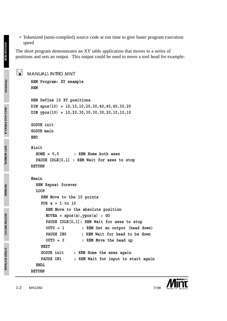
1-2 7/98
• Tokenized (semi-compiled) source code at run time to give faster program executionspeed
The short program demonstrates an XY table application that moves to a series ofpositions and sets an output. This output could be used to move a tool head for example:
! MANUAL\INTRO.MNT
REM Program: XY exampleREM
REM Define 10 XY positions
DIM xpos(10) = 10,10,10,20,30,40,40,40,30,20DIM ypos(10) = 10,20,30,30,30,30,20,10,10,10
GOSUB init
GOSUB main
END
#init
HOME = 0,0 : REM Home both axesPAUSE IDLE[0,1] : REM Wait for axes to stop
RETURN
#main
REM Repeat foreverLOOP
REM Move to the 10 points
FOR a = 1 to 10
REM Move to the absolute positionMOVEA = xpos(a),ypos(a) : GO
PAUSE IDLE[0,1]: REM Wait for axes to stop
OUT0 = 1 : REM Set an output (head down)
PAUSE IN0 : REM Wait for head to be downOUT0 = 0 : REM Move the head up
NEXT
GOSUB init : REM Home the axes again
PAUSE IN1 : REM Wait for input to start againENDL
RETURN
MN1260

1-37/98
The previous example assumes that all servo loop gains, speeds, accelerations etc. havebeen set-up. MINT uses 2 file buffers, the first buffer is designated the configuration fileand is used to store such information as the servo loop gains and speeds etc. The secondbuffer, the program file stores this actual application. It should therefore be possible towrite an application which is common among different types of motors and to only changethe configuration file when the motor is changed. In fact the two files can accept the sameinstructions, the difference is the size of the files. A configuration file can be up to 1000bytes in length whereas the program file length which can be supported is defined by theavailable memory on the controller. On program execution, the configuration file is firstexecuted followed by the program file. A typical configuration file for the above examplemay be:
! MANUAL\INTRO.CFG
AUTO : REM Auto run program on power up
REM Configuration file for XY table
REM using servos
AXES[0,1] : REM Two axis system
RESET[0,1,2] : REM Reset all axes in the system
CONFIG = _servo,_servo
KVEL = 10; : REM Set velocity feedback for both axesGAIN = 1.5; : REM Set proportional gain for both axes
KINT = 0; : REM Zero integral gain
KINTRANGE = 20; : REM 20%
KVELFF = 0; : REM Zero feedforwardCURRLIMIT = 100; : REM 100%
SCALE = 400; : REM Scale factor. Assume units of mm
SPEED = 200; : REM Speed of 200 mm/sec
ACCEL = 500; : REM Accel of 500 mm/sec^2MFOLERR = 2; : REM Max following error of 2mm
IDLE = .5; : REM Idle position of 0.5mm
RAMP = 0; : REM Trapezoidal
HMSPEED = 50;: REM Datuming speed BACKOFF = 10;: REM Datuming backoff speed factor
ERRORIN = 1 : REM External error state
MN1260

1-4 7/98
The keyword, AUTO, at the top of the configuration file is used to instruct the controllerto automatically run the configuration, then the program file on power-up. AUTO must bethe first command in the configuration otherwise you will be taken to the command line.The command line allows commands to be entered for immediate execution. To execute aprogram without AUTO, the RUN command would be typed in at the command line. Toterminate an executing program, is used from the terminal.
You will note in the example, such keywords as RESET, KVEL and SPEED etc. Theseare motion specific keywords and are used to access motion control and input/outputfeatures of the system. All motion keywords, unlike the BASIC type keywords (forexample: FOR, PRINT, WHILE), can be abbreviated to two letters. For instance, SPEEDis abbreviated to SP which is useful for saving file space.
To access a particular axis, square brackets are used next to the motion keyword. Forexample:
SPEED[1] = 10
or a dot as shown:
SPEED.1 = 10
will set the speed of axis 1 to 10 units where axes are referenced as 0, 1 and 2.
ACCEL[0,1] = 600,800
will set the acceleration of axis 0 to 600 units and axis 1 to 800 units.
a = POS[2]
will assign the position of axis 2 to the user variable a.
In most cases the square brackets are optional.
SPEED[0,1] = 10,20
SPEED = 10,20
are the same depending on the value of the default axes string as defined by the AXESkeyword. The AXES keyword as seen in the configuration file example (of AXES[0,1])tells MINT that all motion keywords relate to 2 axes, i.e. 0 and 1 unless explicitlyindicated by enclosing the axes in square brackets after the keyword. For example:
RESET[0,1,2]as used in the configuration file example will reset various parameters and error flags to aknown state on axes 0,1 and 2.
Multi-axis syntax and the AXES keyword is explained in greater detail in section 3.
MINT by default defines all positional and speed related motion keywords in terms ofencoder quadrature counts for servo motors or steps for stepper motors. Using theSCALE keyword, these keywords can be scaled to your own units to suit your application.The diagram below shows the effect of scaling on positional information:
MN1260

1-57/98
In an XY application, for example, you may want to define all positions in milli-meters orinches.
Example:
An XY table uses servo motors with 500 line encoders and a 4 mil pitch. With quadratureencoder this gives 2000 counts per revolution of the motor or 500 counts per milli-metre.To scale the positions and speeds to milli-meters, the following could be used:
SCALE = 500,500 : REM Scale to mm
SPEED = 30,30 : REM Speed = 30 mm/sec
ACCEL = 500,500 : REM Accel = 500 mm/sec^2
MOVEA = 100,200 : GO : REM Move to position 100,200mm
MOVER = -10,-10 : GO : REM Move relative -10,-10mm
Programs can be entered into the controller memory by either using the onboard editor orwriting a program on an external computer and downloading the program using a terminalemulator. cTERM, a terminal emulator for both DOS and Windows is provided for thispurpose. MINT’s on-board editor provides commands such as INS and DEL to insert anddelete program lines and are discussed in section 9.
1.1 MINT BasicsMINT, as with many other forms of Basic, supports a command line interface. Byconnecting the controller up to a terminal (for example a PC running cTERM — a pre-configured terminal emulator for DOS and Windows for use with the controllers),commands can be typed on to the command line for immediate execution. For example:
PRINT POS
will display the position of the motor.
MN1260

1-6 7/98
Multiple commands can also be entered by separating the commands with colon (:). Forexample:
MOVEA = 100 : GO : PAUSE IDLE : OUT1 = 1
will move the motor to position 100, wait for it to come to rest and then set output bit 1.
Some commands, such as DIM, COMMSON, COMMSOFF, GOSUB and GOTO cannotbe executed from the command line.
1.1.1 Program Execution and Termination
A program (series of commands) can be created using either an offline editor or the MINTline editor (See section 9 for details on the editor and editor commands). A program, onceentered into the controller can be executed using the RUN command. Alternatively, thecommand AUTO allows the program to be executed automatically on power up.
Once a program is running execution can be terminated by sending Ctrl-E (character 05H)down the serial port. This will terminate program execution and MINT will return withthe message:
Break at line XXX
From the command line, it is possible to execute a continuous loop. In the same way asprogram execution is terminated, Ctrl-E is used to terminate command line execution. Forexample:
LOOP : ? IN : ENDL
If the MINT Comms Protocol is running, Ctrl-E will have no effect. The MINTComms Protocol must be terminated first. See section 12.3.3.1 for details.
1.2 Safety FeaturesBoth the controller card and MINT incorporate a number of safety features. These are:
• End of travel limits resulting in a limit error.
• The setting of a maximum permissible following error (MFOLERR) before cuttingpower to the motors. This is very useful if an axis hits an endstop where the followingerror can build up.
• Stop input to bring all axes to a controlled stop.
• External error input to bring all axes to a crash stop.
MINT has full control over these features, should an error occur, an ONERROR routinewill be called. From the ONERROR routine you can decide to recover from the error orperform a complete system shut-down for example.
MN1260

1-77/98
1.3 MINT VersionsMINT is available in 3 versions:
Process MINT Process MINT, incorporates such motion control features assoftware gearboxes, cam profiles and flying shears. ProcessMINT supports up to 3 axes of linear interpolation but does notsupport circular interpolation.
Is must be noted that Process MINT supports cam profiles andflying shears on the first 2 axes only (Axes 0 and 1).
Interpolation MINT Interpolation MINT provides full linear and circularinterpolation within the MINT environment. InterpolationMINT does not support the cam profiling and flying shearcapabilities of Process MINT. A subset of Process MINT’ssoftware gearboxes are supported.
MINT/3.28 MINT/3.28 is intended specifically for systems where a hostcomputer sends motion control commands to the controller inreal time. Motion control programs are not supported on thecontroller, but commands are sent by a host computer by meansof datapackets.
MINT/3.28 only supports a subset of the MINT command set,namely the motion control commands. The Process MINTcommand set is not supported.
MINT/3.28 will operate over either an RS232 or RS485 link.The physical constraints of RS232 allow only point-to-pointcommunication, i.e. one host computer can talk to onecontroller, RS485 provides longer transmission distances andallows a single host computer to communicate with up to 16controllers on one multi-drop link.
Within a multi-drop 485 system using MINT/3.28, a controllercannot act as a host to other controllers on the system.
1.4 Systems with more than Three Axes (multi-drop)MINT only supports the control of 3 axes on one controller. However, using a hostcomputer based system it is possible to connect up to 16 controllers on to a multi-dropRS485 serial link and to issue instructions to these controllers using specially constructeddata packets.
MN1260

1-8 7/98
Using MINT, it is possible to switchfrom controller to controller over amulti-drop link by sending $followed by the card address. Thecard address is set by the 4 way DIPswitch, details of which can befound in the appropriate hardwareguide. Note that the card addresscan be read using the CARDkeyword.
Example:
$3
will give you control of card 3. Having gained access you can now proceed to upload anddownload programs over the multi-drop link.
To gain access to cards 10 to 15, send $A to $F (note that addresses A to F are in capitals)
It is also possible to pass data to an executing program or to issue commands forimmediate execution using one of two protocols.
MINT Host Computer Communications (Comms Protocol)In MINT data can be passed to and from the controller using a protected data packet into a99 element array on the controller. This is analogous to a mail-box with 99 pigeon holes.The host computer can place data into a pigeon hole for the controller to read and viceversa which occurs during program execution. See section 12 for full details of theComms Protocol. An example of the comms protocol is given in the applications sectionof the Getting Started Guide.
MINT/3.28MINT/3.28 is intended specifically for systems where a host computer sends motioncontrol commands to the controller in real time. MINT/3.28 is a data-packet basedsystem used for communications over the RS232 or RS485 serial communications links.The physical constraints of RS232 allow only point-to-point communication, i.e. onehost computer can talk to one controller, RS485 provides longer transmission distancesand allows a single host computer to communicate with up to 16 controllers on onemulti-drop link. Each controller has a unique address set by a switch on the controllercard. MINT/3.28 is not standard software and requires a firmware change. Pleasecontact your distributor for details. See section 13 for full details of MINT/3.28
Both protocols are defined by the ANSI standard 3.28, which consists of a card addressfollowed by data and a checksum, allowing both systems to be shared on the samemulti-drop link. The checksum ensures fault tolerant communications between host andcontroller.
MN1260

2-17/98
2. Program StructureApplication programs in MINT are made up of a configuration file and a program file.The configuration file should store all the set up and initialization commands and theprogram file the actual application itself.
The following examples show the sort of structure that is recommended when writingMINT applications:
Configuration file for a servo system:
! MANUAL\TEMPLATE.CFG
AUTO : REM Auto run programREM Project ...REM Author ....REM Date ......
AXES[0,1]RESET[0,1,2] : REM Clear all axes in the systemCONFIG = _servo, _servoREM Set servo loop parametersKVEL = 10;GAIN = 2;KINT = 0;KINTRANGE = 25;KVELFF = 0;CURRLIMIT = 0;REM Set scaling factor and all scaled variablesSCALE = 500;SPEED = 20;ACCEL = 700;HMSPEED = 10;BACKOFF = 5;IDLE = .25;MFOLERR = 2;RAMP = 1;
You are recommended to read the Getting Started Guide to determine the best gains for the system.
MN1260

2-2 7/98
Configuration file for a stepper system:
AUTO : REM Auto run programREM Project ...REM Author ....REM Date ......AXES[0,1]RESET[0,1,2] : REM Clear all axes in the systemCONFIG = _stepper, _stepperREM Set scaling factor and all scaled variablesSCALE = 500;SPEED = 20;ACCEL = 700;HMSPEED = 10;BACKOFF = 5;IDLE = .25;RAMP = 1;
Program file:
! MANUAL\TEMPLATE.MNTREM Program fileRME Project ..REM Author ...REM Date .....
GOSUB initGOSUB mainEND
REM Setup all global variables here#init
my_var1 = 1newPos = 1000
RETURN
REM Main loop here#mainLOOP
REM Place main code hereENDLRETURN
REM Define rest of subroutines here
the subroutine init is used to define all global variables used within the system. This mustbe placed at the beginning of the program since variables are defined at compile time andnot run time.
See section 4.4.1 on how to implement non-volatile variables.
MN1260

MN1260 3-17/98
3. Multi-axis Syntax and Motion KeywordsMotion keywords can be broken down into 2 groups:
1. Motion commands
2. Motion variables
3.1 Motion CommandsMotion commands are used very much like a Basic command such as PRINT. Forexample:
STOP
will bring the axes to a controlled stop.
GO[0,1]
will begin motion on axes 0 and 1. Note the use of square brackets to reference axes.This is explained in detail later on.
3.2 Motion VariablesA motion variable is used very much like a user or Basic type variable in that it can bewritten to or read from. For example:
GAIN = 1 : REM Set the proportional gainPRINT POS : REM Print the current position
Some motion variables are read only and some are write only. For example:
a = OUT1
is invalid since OUT1 is a write only variable that is used to set the value of digital outputbit 1.
VEL = 0is invalid since VEL is a read only variable that returns the instantaneous velocity of themotor.
Motion variables are range checked when written to. For example:
SCALE = -1
will display the error message “ERROR: Out of range” (if a terminal is connected)because SCALE only accepts a value between 1 and 65000.
Square brackets are used to reference axes as for motion commands. For example:
SPEED[1,2] = 10,20

MN12603-2 7/98
set the speed of axis 1 to 10 units and axis 2 to 20 units. Multi-axis syntax is explained indetail in the next section.
3.3 Multi-Axis SyntaxWith the exception of a few motion keywords, motion keywords are axis related in thatsetting the speed, for example, on one axis has no effect on the speed of the other axes.MINT’s multi-axis syntax supports up to 3 axes on one controller.
MINT uses the convention of axis number 0 to refer to the first axis, axis number 1 torefer to the second axis and so on.
In a single axis system, you do not have to specify the axis number explicitly since MINTwill default to axis 0 (the first axis in the system). Therefore:
GAIN = 1will set the proportional gain on axis 0 to 1.
In a multi-axis system, each axis is referenced by enclosing the axis numbers in squarebrackets [] immediately after the motion keyword. For example, to set the speed of axis 0and 1 to 10 and 30 respectively:
SPEED[0,1] = 10,30
or:
SPEED[1,0] = 30,10
The number of parameters following the equal sign cannot be greater than the number ofaxes given except in a few cases (see CIRCLEA and CIRCLER). The following isinvalid:
MOVEA[0,1] = 100,150,500where MOVEA is used to set-up an absolute positional move. However:
MOVEA[0,1,2] = 10,20
is valid and will set-up an absolute move on axis 0 and 1 only of 10 and 20 unitsrespectively.
Variables can be used as axis numbers:
MOVER[a] = 100
is valid provided a is in the range of 0 <= a <= 2.
MOVER[a+1] = 100
is invalid. The expression “a+1” must be assigned to a variable before being passed as anaxis number.

MN1260 3-37/98
The keyword AXES is used to set-up a default axis string. For example:
AXES[0,1]
SCALE = 10,10SPEED = 200,300
ACCEL = 500,500
is the same as:
SCALE[0,1] = 10,10SPEED[0,1] = 200,300
ACCEL[0,1] = 500,500
Not only does the AXES keyword save on typing, but it also speeds up program execution.To see the current status of the AXES keyword, type AXES at the command line. AXESon its own in a program will result in a run time error.
When the controller is first powered up, the AXES keyword will default to the axes 0, 1and 2 (for a 3 axis controller) i.e.:
AXES[0,1,2]With the AXES string set, MINT will apply the following rules: Assuming AXES[0,1]
Example 1: Motion Commands
STOP
will perform a controlled stop on axes 0 and 1 and is equivalent to
STOP[0,1]
Example 2: Writing to Motion Variables
SPEED = 10
will set the speed of axis 0 to 10 and is equivalent to:
SPEED[0] = 10
Example 3: Reading Motion Variables
a = POS
will read the instantaneous position of axis 0 and is equivalent to:
a = POS[0]
With the AXES keyword set a single axis can still be referenced. For example, assumingAXES[0,1,2]:
SPEED = 10
will set the speed of axis 0 to 10
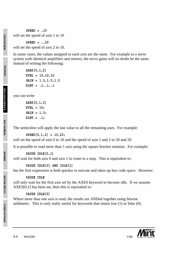
MN12603-4 7/98
SPEED = ,10will set the speed of axis 1 to 10
SPEED = ,,20
will set the speed of axis 2 to 10.
In some cases, the values assigned to each axis are the same. For example in a servosystem with identical amplifiers and motors, the servo gains will no doubt be the same.Instead of writing the following:
AXES[0,1,2]
KVEL = 10,10,10GAIN = 1.5,1.5,1.5
KINT = .1,.1,.1
you can write
AXES[0,1,2]KVEL = 10;
GAIN = 1.5;
KINT = .1;
The semicolon will apply the last value to all the remaining axes. For example:
SPEED[0,1,2] = 10,20;
will set the speed of axis 0 to 10 and the speed of axis 1 and 2 to 20 and 20.
It is possible to read more than 1 axis using the square bracket notation. For example:
PAUSE IDLE[0,1]
will wait for both axis 0 and axis 1 to come to a stop. This is equivalent to:
PAUSE IDLE[0] AND IDLE[1]but the first expression is both quicker to execute and takes up less code space. However:
PAUSE IDLE
will only wait for the first axis set by the AXES keyword to become idle. If we assumeAXES[0,1] has been set, then this is equivalent to:
PAUSE IDLE[0]
Where more than one axis is read, the results are ANDed together using bitwisearithmetic. This is only really useful for keywords that return true (1) or false (0).

3-57/98 MN1260
3.3.1 Single Axis References using Dot
A single axis can be reference using dot ‘.’, followed by the axis number. The axisnumber can be expressed as either a number or a variable. For example:
b = POS.1
is the same as:
b = POS[1]
The first expression has 2 advantage over the second. First, it occupies less code space,and secondly, it executes some 50% quicker.
Note that:
b = POS.a + 1is equivalent to:
b = POS[a] + 1

3-6 7/98MN1260

MN1260 4-17/98
4. MINT Numbers, Variables and Operators
4.1 Numbers
All numbers are represented as a four byte scaled integer. This gives a range of +/-8,388,607.996, where the fractional part has a resolution of one part in 256 or 0.004. Dueto the integer nature of the processor, numbers in MINT are not true floating pointnumbers since this would result in slower program execution. In a linear table application,MINT numbers would give a maximum positional resolution of 1 micron in 16 meters.
Example:
PRINT 1.002will display
1.003
to the terminal. This is because MINT will round the number to the nearest part in 256.The fractional part of a MINT number is calculated as follows:
Given a number of 1.15, what proportion of 256 is the fractional part 0.15 ?
Assuming 3 fractional places, 0.15 can be represented by 150/1000, the internal value of0.15 is given by:
INT( 150 * 256 / 1000 ) = 38
therefore 0.15 is represented as 38/256 or 0.148 (approx.). In fact the statement “PRINT0.15” will display “0.148” to the terminal screen.
4.2 Binary Numbers
Binary numbers are defined by placing a zero before the binary string. For example:
PRINT 011011
will display
27
Binary numbers are useful when writing to outputs. For example:
OUT = 011110000
this will turn the top 4 bits on and the bottom 4 bits off.
a = 11
is not a valid binary number and will assign the value of 11 to the variable a.
a = 05

MN12604-2 7/98
is an invalid binary number and will generate a syntax error, however:
a = 0.5
is acceptable and will define the value of 0.5 to the variable a.
4.3 Constants
A constant is a number in your program that does not change during program execution.For instance, the expression:
SPEED = 20.5assigns the constant value 20.5 to the motion variable SPEED.
MINT accepts four types of constants:
• Constant numbers
• Binary constants
• Character constants
• Pre-defined constant keywords
By default, MINT interprets all constant numbers as decimal unless otherwise specified.Binary constants are defined by prefixing the number with a zero, as discussed in theprevious section.
MINT also provides character constants for use with the INKEY and READKEYcommands. To define a character constant, enclose the character in single quotes, forexample:
a = ‘A’
will assign the value of 65 to a. MINT will convert all character constants to their uppercase equivalent. Therefore:
‘A’
‘a’
both have the value of 65.
Refer to an ASCII character table for the decimal value of each character.

MN1260 4-37/98
Character constants are useful for interpreting key presses as shown in the followingsection of code:
! \MANUAL\CHAR.MNT
#mainMenu
LOOPLOCATE 1,1
?”A .. Start”
?”B .. Setup”
key = INKEY
IF key = ‘A’ THEN GOSUB start
IF key = ‘B’ THEN GOSUB setup
ENDLRETURN
#start
...RETURN
#setup
...RETURN
If key ‘A’ is pressed, the start subroutine will be called. If ‘B’ is pressed, set-up will becalled.
4.3.1 Pre-defined Constant KeywordsMINT has a number of pre-defined constant keywords that can be used to aid thereadability of programs. All constants begin with an underscore to distinguish them fromother MINT variables.
Examples:
OFFSET = 10 : PAUSE mode = _pulse : REM Wait for offset to finishOUT1 = _on : REM Switch output bit 1 on
IF ERROR = _limit THEN DL : REM Limit Error
CONFIG = _stepper : REM Configure for stepper mode
HOME = _posindex : REM home in pos direction and seek index

MN12604-4 7/98
A complete list of the MINT constants is shown below:
Constant Name Value Associated Keyword
_true 1
_false 0
_on 1
_off 0
_idle 0 MODE
_servoff 1 MODE
_linear 2 MODE
_jog 3 MODE
_circular 4 MODE
_pulse 5 MODE
_torque 6 MODE
_homing 7 MODE
_offset 8 MODE
_follow 9 MODE
_abort 1 ERROR
_maxfe 2 ERROR
_limit 3 ERROR
_external 11 ERROR
_servo 1 CONFIG
_stepper 2 CONFIG
_micro 3 CONFIG
_neg 0 HOME
_negindex 1 HOME
_pos 2 HOME
_posindex 3 HOME
_lcd 1 TERM
_serial 2 TERM
_both 3 TERM

MN1260 4-57/98
4.4 VariablesVariables are meaningful names that are used to represent data in a program. You canassign a value to a variable at the beginning of a program and use it like a constant, or itsvalue may be set as the result of calculations or incremented in a loop. These variablesare referred to as user variables to distinguish them from motion variables which arereserved keywords in MINT used to perform a specific task.
User variables can have any name as long as it is not a reserved word or MINT keywordand begins with a letter followed by any alphanumeric character or an underscore.Alternatively, variable names can begin with an underscore as long as it is followed by analphanumeric. Variable names may be any length but only the first ten characters aresignificant.
Examples of variable names:
my_var1
xPosition
_myVar2Unlike many implementations of BASIC, variables must be declared before being used,otherwise an error is generated. A variable declaration is any valid assignment to thevariable. For example:
aVar = 10
bVar = aVar
will define variables aVar and bVar if they are not already defined and give them a valueof 10.
It should also be noted that the following statements will also define a variable:
FOR .. NEXT
DIM
INPUT
Variables can be used in any valid expression. For example:
newPos = 2oldPos = newPos*2
PRINT oldPos+newPos
Running this code fragment will define variables oldPos and newPos and print the value 6to the screen.
An extensive range of operators can be used on numbers and variables. These arediscussed in more detail in a later section.
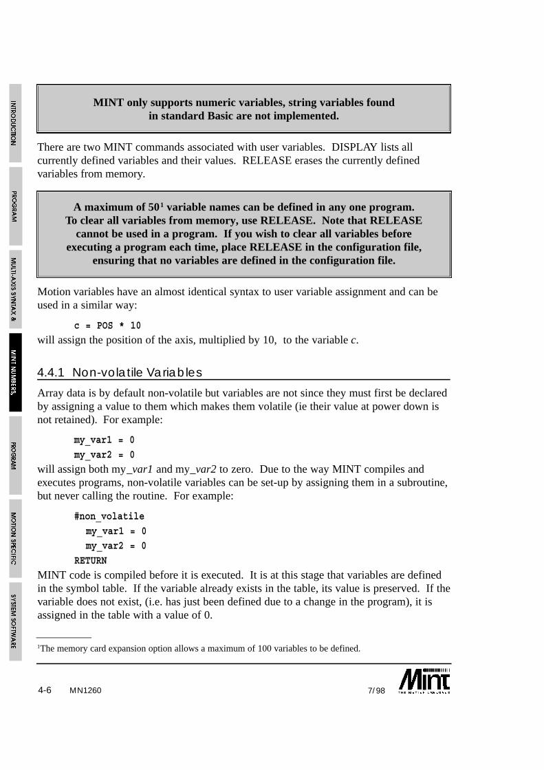
MN12604-6 7/98
MINT only supports numeric variables, string variables foundin standard Basic are not implemented.
There are two MINT commands associated with user variables. DISPLAY lists allcurrently defined variables and their values. RELEASE erases the currently definedvariables from memory.
A maximum of 501 variable names can be defined in any one program.To clear all variables from memory, use RELEASE. Note that RELEASE
cannot be used in a program. If you wish to clear all variables beforeexecuting a program each time, place RELEASE in the configuration file,
ensuring that no variables are defined in the configuration file.
Motion variables have an almost identical syntax to user variable assignment and can beused in a similar way:
c = POS * 10
will assign the position of the axis, multiplied by 10, to the variable c.
4.4.1 Non-volatile Variables
Array data is by default non-volatile but variables are not since they must first be declaredby assigning a value to them which makes them volatile (ie their value at power down isnot retained). For example:
my_var1 = 0
my_var2 = 0
will assign both my_var1 and my_var2 to zero. Due to the way MINT compiles andexecutes programs, non-volatile variables can be set-up by assigning them in a subroutine,but never calling the routine. For example:
#non_volatile
my_var1 = 0my_var2 = 0
RETURN
MINT code is compiled before it is executed. It is at this stage that variables are definedin the symbol table. If the variable already exists in the table, its value is preserved. If thevariable does not exist, (i.e. has just been defined due to a change in the program), it isassigned in the table with a value of 0.
1The memory card expansion option allows a maximum of 100 variables to be defined.

MN1260 4-77/98
To work correctly, the non_volatile subroutine must be placed near the beginning of theprogram before any other references to the variables, otherwise an undefined variable errorwill be issued during compilation. A program structure may be as follows:
! MANUAL\NONVOL1.MNT
REM Program title
GOSUB init : REM InitializeGOSUB main : REM Main program loop
END
#non_volatilemy_var1 = 0
my_var2 = 0
RETURN
REM Rest of program here
#init
RETURN
REM Main Program loop
#main
RETURN
It may be that on first running a program, you want variables to default to a value otherthan zero. This can be done by checking a non-volatile variable as shown:
! MANUAL\NONVOL2.MNT
REM Program title
REM Check variables have been definedIF non_volatile = _false THEN GOSUB default
GOSUB init : REM InitializeGOSUB main : REM Main program loop
END
REM Declare non volatile variables#non_volatile
non_volatile = 0RETURN

MN12604-8 7/98
REM Declare variable and initialize them#default
non_volatile = _truemy_var1 = 10my_var2 = 20
RETURN
REM Rest of program here#init
RETURN
REM Main loop#main
RETURN
When the program is first executed the variable non_volatile is defined as zero and theroutine default executed. When the program is re-executed, the routine default will beignored since non_volatile is now 1.
4.5 ArraysAn array is a table of values that is referenced by a single name. Each value in the arrayis called an element. Elements are numeric variables that can be used in expressions andMINT statements in the same way as simple variables described previously. Each elementin the array is referenced by a number in parentheses which follows the array name, thisnumber is termed an index. Note that the index is always enclosed in round brackets todistinguish it from a reference to axis numbers which are in square brackets. Forexample:
my_var(10) = 100.5
will assign the value 100.5 to the array variable my_var index 10
a = my_var(10)
will assign the value of array variable my_var index 10 to the variable a.
Before using an array variable, memory space must be reserved for it’s storage by use ofthe DIM statement:
DIM my_array(10)
declares an array variable called my_array with ten elements.
PRINT my_array(4)
will print the contents of element four to the user terminal. Array variables are very usefulfor motion control applications since they can be used for storing a large number of data
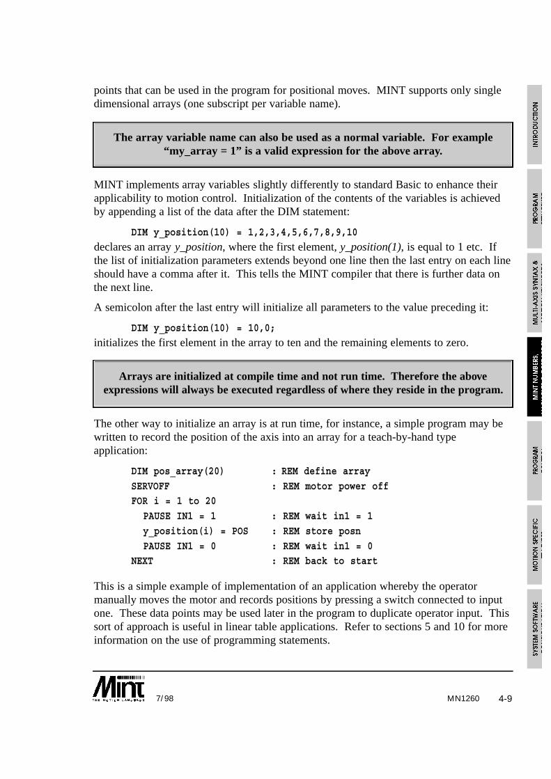
MN1260 4-97/98
points that can be used in the program for positional moves. MINT supports only singledimensional arrays (one subscript per variable name).
The array variable name can also be used as a normal variable. For example“my_array = 1” is a valid expression for the above array.
MINT implements array variables slightly differently to standard Basic to enhance theirapplicability to motion control. Initialization of the contents of the variables is achievedby appending a list of the data after the DIM statement:
DIM y_position(10) = 1,2,3,4,5,6,7,8,9,10
declares an array y_position, where the first element, y_position(1), is equal to 1 etc. Ifthe list of initialization parameters extends beyond one line then the last entry on each lineshould have a comma after it. This tells the MINT compiler that there is further data onthe next line.
A semicolon after the last entry will initialize all parameters to the value preceding it:
DIM y_position(10) = 10,0;
initializes the first element in the array to ten and the remaining elements to zero.
Arrays are initialized at compile time and not run time. Therefore the aboveexpressions will always be executed regardless of where they reside in the program.
The other way to initialize an array is at run time, for instance, a simple program may bewritten to record the position of the axis into an array for a teach-by-hand typeapplication:
DIM pos_array(20) : REM define array
SERVOFF : REM motor power offFOR i = 1 to 20
PAUSE IN1 = 1 : REM wait in1 = 1
y_position(i) = POS : REM store posn
PAUSE IN1 = 0 : REM wait in1 = 0NEXT : REM back to start
This is a simple example of implementation of an application whereby the operatormanually moves the motor and records positions by pressing a switch connected to inputone. These data points may be used later in the program to duplicate operator input. Thissort of approach is useful in linear table applications. Refer to sections 5 and 10 for moreinformation on the use of programming statements.

4-10 7/98MN1260
One important difference between MINT and standard Basic is that array variables are notinitialized to zero at run time. This means that data stored in previous executions of theprogram is not lost when the system is turned off.
You have seen how a series of points can be stored in an array in a teach-by-handapplication. Entering this data may be a long process, so it is recommended that you savea back-up copy to disk. Array data may be uploaded and stored on a disk by using astandard terminal emulation program such as the one supplied on disk with this manual(cTERM).
Upload and Download facilities allow you to teach a machine a series of points which arestored as array data, upload the data into your computer using the SAVE command, storeas it a file and then download it, using the LOAD command, to any number of identicalcontrollers. Alternatively, with a memory card attached, array data can be saved andrestored to a memory card, again using the LOAD and SAVE keywords. More detailsabout saving and restoring array data is contained in the following sections.
4.5.1 Off-line Array Storage
A memory card interface is available which supports a 64K or 128K RAM (SmartMoveonly) for memory expansion. The memory card interface is either built into the controller(as with SmartMove), or is supplied as an expansion card. Section 9.1 containsinformation on using the memory card for memory expansion. This sections deals withusing the memory card for expansion of array data.
Consider the following example:
DIM OFFLINE xpos(1000)DIM OFFLINE ypos(1000)
DIM zpos(50)
SERVOFFFOR a = 1 TO 1000
PAUSE IN1 : REM Wait for input 1
xpos(a) = POS.0
ypos(a) = POS.1NEXT
The array data xpos and ypos have both been defined as residing off-line on the memorycard by use of the OFFLINE keyword within the DIM statement. No internal memory isused by the array data. zpos on the other hand resides within the controller memoryspace. Offline array data can then be used throughout the program as though the dataresides within the controller address space.

MN1260 4-117/98
With a 64K RAM card, some 64,256 bytes of memory are free or up to 16,064 arrayelements. A 128K RAM card, as supported by SmartMove, will double this amount of data.
Memory cards can be swapped at any time during program execution, therefore makingthe number of array elements for any program limitless. A memory card must be in placeduring program compilation otherwise an “Out of Memory” error will result. It will thenbe necessary to replace the memory card and reset the controller.
The memory card can still be used in the normal manner, allowing a program andconfiguration file to be saved as well as on board array data. A 64K memory card is splitinto the following configuration:
If a program and array data are not saved to the memory card, this memory is available foroff-line array data. It must be noted that off-line array can over-write the Array Dataspace as shown above. It is up to the user program to ensure this does not happen.
A 128K RAM card provides an additional 64K of data above the address FF00H. The topmost address becomes 1FF00H.
A cam table must be declared online. Using OFFLINE to declare a cam tablewill result in an “Out of Range” error when the cam is executed.
To further increase the size of MINT program files, the memory expansion firmwareoption should be used. This is denoted by /MX in the version number and increasesmemory size by storing the configuration and program files on the memory card, not onthe controller. See section 9.1.

4-12 7/98MN1260
4.5.2 Advanced use of Arrays
Consider an insertion application, whereby the machine must repeatedly move through aseries of points and perform an insertion operation, but different work-pieces require adifferent series of positions. This is an ideal application for array data.
The following code fragment defines two arrays, X and Y, that store fifty data points eachfor an X-Y insertion application:
DIM X(50)
DIM Y(50)
A program to read the data in the arrays and perform the insertion might look somethinglike this (the exact syntax of the move instructions is covered in later sections of thismanual, consider for now only the way that we use the data):
FOR I = 1 TO 50MOVEA = X(I),Y(I) : REM read Ith elements
GO
PAUSE IDLE[0,1] : REM wait for move to finish
OUT1 = 1 : REM output one is connected to..
WAIT = 50 : REM .. the insertion machineOUT1 = 0
NEXT
The statement MOVEA = X(I),Y(I) selects the Ith element of the arrays as the positionsfor the Ith iteration of the FOR loop. If different jobs require different numbers ofinsertion operations, we would probably store the maximum value of the loop as avariable as well.
Array data is stored in the controller memory as a table of four byte variables. Data spaceis limited by memory on board the controller to approximately 4000 elements, dependingon the size of the application program (this can be increased using a memory card and theOFFLINE keyword). Each element is a scaled integer like normal MINT variables, wherethe top three bytes represent an integer value in the range ±8,388,607 and the lower byte isa fractional part with a resolution of 1/256.
The statements:
DIM X(50)
DIM Y(50)
reserve a one hundred element (400 byte) long table of data in the controller’s memory.
For advanced users, it is possible to externally generate the array data for X and Y in theexample program above and download this is to the host without loading a new program.This data might be generated by any application that can produce a series of numbers in

4-137/98 MN1260
ASCII format. For instance, if you wished to interface a CAD (Computer Aided Design)system with your insertion machine, you could write a program that generated the dataformatted as specified in the next section.
Example Program: Teach and Replay
This simple example uses arrays to record 10 XY positions. The operator uses a joystickto move the table around; 3 operator panel keys are labeled ‘teach’ ‘replay’ and ‘record’,which return ‘A’ ‘B’ & ‘C’ up the RS232 port.
Using array data files, it is possible to learn a series of points and to save the array datausing the SAVE command. Likewise, the data can be edited using any standard texteditor, and the new data loaded using the LOAD command.
! MANUAL\TEACH.MNT
REM XY Table Example: teach and replayREM for an insertion application
DIM x_position(10) : REM 10 points of data
DIM y_position(10)GOSUB main
END
#mainLOOP
PRINT “Press Teach or Replay”
key = 0
REM Wait for a key to be pressedWHILE key = 0
key = INKEY : REM Read keyboard
IF key = ‘A’ THEN GOSUB teach
IF key = ‘B’ THEN GOSUB replay
ENDWENDL
RETURN
REM Subroutine to teach points and record in arrays#teach
PRINT “Teach mode” BEEP
WAIT = 1000 : REM Wait one second

MN12604-14 7/98
FOR point = 1 to 10PRINT “Move to position “,point
REPEAT : REM repeat until record button is pressed
REM jog at X,Y speed given by analog inputs, range ..
REM is 0-1024, subtract 512 to give bi-directional controljog_x = ANALOGUE1-512
jog_y = ANALOGUE2-512
REM deadband of 4 points either side of zero
IF ABS(jog_x) < 4 THEN jog_x = 0IF ABS(jog_y) < 4 THEN jog_y = 0
JOG = jog_x, jog_y
UNTIL INKEY = ‘C’
STOP : REM stop jog motionPAUSE IDLE[0,1] : REM wait until stationary
x_position(point) = POS[0] : REM Read position of X axis
y_position(point) = POS[1] : REM Read position of Y axis
NEXT : REM get next pointRETURN
REM Replay learned points, go to Home position first
#replay
HOME = 1; : REM go to home position firstPRINT “Replay mode” :BEEP
FOR point = 1 TO 10
VECTORA = x_position(point), y_position(point)
GONEXT
RETURN
4.5.3 Array Data File Format
When array data is saved, using cTERM for example, it is saved in an ASCII format. Thismeans that the file can be read using a standard text editor and array values modified ifnecessary. An example file is shown:
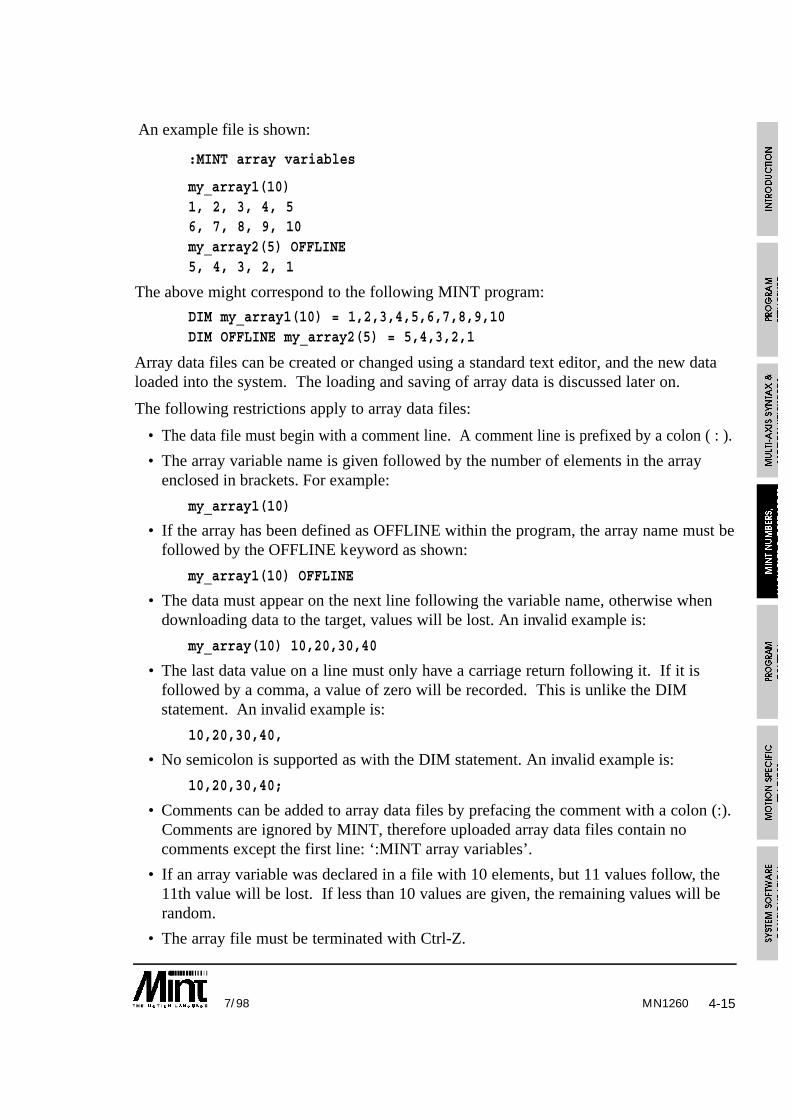
MN1260 4-157/98
An example file is shown:
:MINT array variables
my_array1(10)1, 2, 3, 4, 56, 7, 8, 9, 10my_array2(5) OFFLINE5, 4, 3, 2, 1
The above might correspond to the following MINT program:
DIM my_array1(10) = 1,2,3,4,5,6,7,8,9,10DIM OFFLINE my_array2(5) = 5,4,3,2,1
Array data files can be created or changed using a standard text editor, and the new dataloaded into the system. The loading and saving of array data is discussed later on.
The following restrictions apply to array data files:
• The data file must begin with a comment line. A comment line is prefixed by a colon ( : ).
• The array variable name is given followed by the number of elements in the arrayenclosed in brackets. For example:
my_array1(10)
• If the array has been defined as OFFLINE within the program, the array name must befollowed by the OFFLINE keyword as shown:
my_array1(10) OFFLINE
• The data must appear on the next line following the variable name, otherwise whendownloading data to the target, values will be lost. An invalid example is:
my_array(10) 10,20,30,40
• The last data value on a line must only have a carriage return following it. If it isfollowed by a comma, a value of zero will be recorded. This is unlike the DIMstatement. An invalid example is:
10,20,30,40,
• No semicolon is supported as with the DIM statement. An invalid example is:
10,20,30,40;
• Comments can be added to array data files by prefacing the comment with a colon (:).Comments are ignored by MINT, therefore uploaded array data files contain nocomments except the first line: ‘:MINT array variables’.
• If an array variable was declared in a file with 10 elements, but 11 values follow, the11th value will be lost. If less than 10 values are given, the remaining values will berandom.
• The array file must be terminated with Ctrl-Z.

MN12604-16 7/98
A very important point to make is that the array data file must contain the same number ofarray definitions and be in the same order as the MINT program file. If not, then data willbe lost or be incorrect. When the array data file is downloaded, or a MINT programexecuted, MINT will reserve space in memory. The order of where the data lies inmemory is defined by the order of the declarations.
Program File Array Data File
DIM xpos(100) xpos(100)DIM ypos(100) 1,2,3,4DIM cam0(201) …DIM minc0(200) ypos(100)
1,2,3,4…cam0(201)200,1,2,3,4…minc0(200)1,2,3,4…
An example of an invalid array file is shown:
Assume the target has the following array variable defined:
my_array(10)
The array data file defines the following array variables:
my_array2(10)
1,2,3,4,5
6,7,8,9,0
my_array3(10)
10,20,30,40,50
60,70,80,90,100
When this file is loaded into the target, typing DISPLAY will show that the values ofmy_array are the same as that of my_array2. If a value is assigned to my_array2, it willalso be assigned to my_array as shown on page 4-17.
DIM my_array(10)
my_array2(5) = 12.5
PRINT my_array(5)
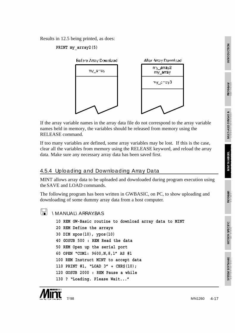
MN1260 4-177/98
Results in 12.5 being printed, as does:
PRINT my_array2(5)
If the array variable names in the array data file do not correspond to the array variablenames held in memory, the variables should be released from memory using theRELEASE command.
If too many variables are defined, some array variables may be lost. If this is the case,clear all the variables from memory using the RELEASE keyword, and reload the arraydata. Make sure any necessary array data has been saved first.
4.5.4 Uploading and Downloading Array Data
MINT allows array data to be uploaded and downloaded during program execution usingthe SAVE and LOAD commands.
The following program has been written in GWBASIC, on PC, to show uploading anddownloading of some dummy array data from a host computer.
! \MANUAL\ARRAY.BAS
10 REM GW-Basic routine to download array data to MINT
20 REM Define the arrays
30 DIM xpos(10), ypos(10)40 GOSUB 500 : REM Read the data
50 REM Open up the serial port
60 OPEN “COM1: 9600,N,8,1” AS #1
100 REM Instruct MINT to accept data110 PRINT #1, “LOAD 3” + CHR$(10);
120 GOSUB 2000 : REM Pause a while
130 ? “Loading. Please Wait...”

MN12604-18 7/98
150 REM Send the data160 PRINT #1, “xpos(10)” + CHR$(10);
170 GOSUB 2000
180 FOR a = 1 TO 9 : REM Send 1st 9 elements of data separated by ,
190 PRINT #1, xpos(a);”,”;200 NEXT
210 PRINT #1, xpos(10); CHR$(10); : REM Send last element
220 GOSUB 2000
230 PRINT #1, “ypos(10)” + CHR$(10);240 GOSUB 2000
250 FOR a = 1 TO 9 : REM Send 1st 9 elements of data separated by ,
260 PRINT #1, ypos(a);”,”;
270 NEXT280 PRINT #1, ypos(10); CHR$(10); : REM Send last element
290 GOSUB 2000
300 PRINT #1, CHR$(26) : REM Send EOF
310 CLOSE #1 : REM Close file320 ? “Done”
400 END
500 REM Read the data
510 FOR a = 1 TO 10
520 READ xpos(a)530 NEXT
540 FOR a = 1 TO 10
550 READ ypos(a)
560 NEXT570 RETURN
1000 DATA 10,20,30,40,50,60,70,80,90,100
1010 DATA 100,90,80,70,60,50,40,30,20,10
2000 FOR x = 1 TO 5000 : NEXT : RETURN
Note the use of ‘chr$(10);’ to add line breaks. The semicolon suppresses thecarriage return, line break combination.
cTERM can also be used to upload and download data during program execution. WhencTERM requests array data to be downloaded (load), for example, it will send down thestring “LOAD” followed by “3” for array data and wait for the reply “Ok 3” from thecontroller. The following MINT program will load data when requested by cTERM:

MN1260 4-197/98
LOOP{ statements }
REM L Received, therefore load data
IF INKEY = ‘L’ THEN GOSUB loadData
{ statements }ENDL
END
#loadDataTIME = 0
REPEAT
REM IF 3 received for array, accept the data
IF INKEY = ‘3’ THEN PRINT “Ok 3”: LOAD 3: EXITREM Timeout after 1000 milli-seconds
UNTIL TIME > 1000
RETURN
The program on receiving ‘L’ will call the subroutine to load data. On receiving the 3, itwill acknowledge the instruction and load the data. If ‘3’ is not received, the routine willtime out. Note the use of the TIME keyword to give a 1000 milli-second time out period.
It may be necessary to upload and download data from your own front end program. TheApplications and Utilities diskette provides upload and download routines written in the Cprogramming language for this purpose. These routines allow you to upload anddownload programs and array data and include the routines for the checksum calculationto ensure correct transmission.
Note: The MINT Interface Library is a range of functions and librariesfor Windows platforms for code development under C/C++, Borland
Delphi and Microsoft Visual Basic. The MINT Interface Library providesmore functionality than the example files included.
This can be purchased separately.
MN12604-20 7/98
4.6 Relational and Mathematical OperatorsA wide range of powerful relational and mathematical operators are available in MINT.These are used to construct expressions for conditional statements and loops, and toevaluate expressions:
* / + - Maths operators
> Greater than
< Less than
= Equals
>= Greater than or equals
<= Less than or equals
<> Does not equal
MOD/% Modular arithmetic
AND/& Bitwise and logical AND
OR/| Bitwise and logical OR
~ Toggle all the bits in a byte
NOT/! Unary not
ABS() Absolute value of number
INT() Integer value of number
COS() Cosine of number
SIN() Sine of number
TAN() Tangent of number
When an expression is evaluated certain operators have precedence over others . Forexample, the expression 2+3*4 evaluates to 14, because ‘*’ has a higher precedence than‘+’. All expressions in brackets are evaluated first. The full range is precedence,including arithmetic operators, is:
Highest ( )NOT/! ~
* / %
+ -
< > <= >== <>
AND/&
Lowest OR/|

4-217/98 MN1260
All relational and logical operators are supported within expressions. These can be usedto construct very powerful conditional statements with ease:
IF IN1 AND (IN2 OR POS > 100) THEN {statement}
Motion variables that can be read are valid within conditional statements, for instance:
PAUSE POS > 50 OR IN1 = 1
will suspend program execution until the position is greater than 50 or input one is high.Any expression or constant that is non zero is defined as true and any that is zero isdefined as false. This gives the user a lot of flexibility in the termination of loops.
count = 1
WHILE IN1 AND count < 100
count = count + 1...
ENDW
will terminate when digital input 1 goes low or count reaches 100.
4.6.1 Performing Bitwise Operations
Logical operators AND/& and OR/| can be used for more than simple comparisons, sincethey actually perform bitwise operations on the variables. For instance, consider theexpression:
5 & 6
is evaluated to 4 i.e. in its binary representation:
0101 & 0100 = 0100
The AND/& operator can therefore be used to mask inputs in conditional expressions:
PAUSE IN AND 12
PAUSE IN2 = 1 OR IN3 = 1
are equivalent since 12 (1100 binary) masks off the lower bits of the inputs (IN is a fourbit binary representation of digital inputs one to four). The advantage of the first option isthat it will execute faster. A binary constant could be used to make the expression morereadable:
PAUSE IN AND 01100PAUSE IN AND 12
are equivalent.
MN12604-22 7/98
OUT = OUT & 15will clear the digital output bits 4 to 7 leaving bit 0 to 3 intact.
OUT = OUT | 15
will set output bits 0 to 3, leaving bits 4 to 7 intact where OUT is used to set the eightdigital output bits. Reading OUT will return the last value written to the outputs.
4.6.2 Trigonometric Functions
The trigonometric functions SIN, COS and TAN are available using the keywords SIN,COS and TAN. There are no inverse functions.
Due to the inaccuracy of floating point numbers in MINT, the values returned from thetrigonometric functions are scaled by a factor a 1000. For example:
SIN 30will return 500.
All the functions will accept an angle in the range of 0 to 360 degrees. Lookup isperformed on a 90 degree table with 1000 elements. This will give an accuracy of approx.1/10th of a degree.
The angle can be expressed as any valid MINT expression but brackets must be used asfollows:
SIN 90 + a
is not the same as:
SIN(90 + a)
The first expression is equivalent to:
(SIN(90)) + a
MN1260 5-17/98
5. Program Control
5.1 Conditional StatementsThree conditional statements are supported in MINT.
• IF .. THEN• IF block structure.
• PAUSE
5.1.1 IF ..THEN statement
Format:
IF <condition> THEN <statements>
The simple IF .. THEN statement is the same as standard versions in Basic. If thecondition is true the statements following THEN and up to the end of the line areexecuted. The condition can be any valid expression, full details of the alternatives aregiven in the section on relational operators.
Examples:
IF POS[1] > 100 THEN SP = 20
IF (a > 12) AND (in1 OR (b > 20)) THEN GOSUB label1Multiple statements are separated by colons if they are to be executed in the same ifstatement.
Example:
IF IN3 THEN STOP : PAUSE IDLE : OUT0 = _off
Note that there is no ELSE statement with the simple IF statement, the IF block structuremust be used if an ELSE is required.
5.1.2 IF block structure
Whereas the IF THEN statement can only be used to conditionally execute a single line ofcommands, the IF block structure can execute a series of commands. It has the followingstructure.
Format:
IF condition DO
{statements} : REM Execute if condition is true
{ELSE
statements} : REM Execute if condition is falseENDIF
MN12605-2 7/98
If the condition is true, the statements up to the ELSE or ENDIF will be executed. If thecondition is false, the statements after the ELSE or ENDIF statement will be executed.The ELSE is optional, statements following the ELSE will be executed only if thecondition is false.
Example 1:
IF INKEY = ‘A’ DO
OUT1 = _onFOR a = 1 to 10
VR = pos_x(a), pos_y(a) : GO
NEXT
OUT1 = _offELSE
JOG = 40, 50
ENDIF
Example 2:IF IN2 OR !IN4 DO
STOP
PAUSE IDLE[0,1]
OUT1 = _on
ENDIF
IF THEN should be used for execution speed if no ELSE is required andall the statements can fit onto one line.
IF .. ENDIF constructs can be nested (IF within an IF) up to 30 levels. An example of twolevels of nesting is:
IF a = 5 DO
{statements}IF b = 2 DO
c = 3
{statements}
ENDIF{statements}
ELSE
d = 1
ENDIF

MN1260 5-37/98
5.1.3 PAUSE statement
Format:
PAUSE <expression>
The PAUSE keyword stops program execution until condition a is true. This has manyuses in synchronizing motion and waiting for inputs.
For example:
PAUSE IN1 = 1
will halt program execution until input bit 1 reads 1. Alternatively:
PAUSE IN1is the same as the previous example but is quicker to evaluate and saves code space.
PAUSE !IN1
PAUSE IN1
pause until a rising edge is seen on input bit 1.
PAUSE POS > 300
pauses until POS (axis position) is greater than 300. Due to the finite time that this looptakes to operate, the axis position upon executing the next line of code may be slightlygreater than 300, especially at high motor speeds.
Example 2:
PAUSE IDLE[0,1]
will pause until both axis 0 and axis 1 are idle. i.e. the mode is zero.
PAUSE with no parameters will stop program execution until a key is pressed at the user’sterminal. This is useful for operator interaction. Using INKEY to read the keyboard, thestatement:
PAUSE INKEY = ‘y’
will suspend program execution until key ‘y’ is pressed.
PAUSE INKEYwill wait for any key press.
PAUSE INKEY = 0
will clear the serial port buffer.
MN12605-4 7/98
5.2 LoopsLoops in MINT allow the execution of a block of statements a number of times, or whileor until a condition is true. Four loop structures are supported in MINT.
FOR .. NEXT
REPEAT .. UNTIL
WHILE .. ENDW
LOOP .. ENDL
5.2.1 FOR .. NEXT loop
The FOR .. NEXT loop executes a fixed number of times set by the value of an indexvariable, a step size and start and stop values for the index. The increment or decrementof the index on each iteration is defined by the STEP keyword. The start and end valuescan be any valid expression. All FOR loops are terminated with a NEXT statement.Unlike the standard implementation of BASIC you must not append the index name afterthe NEXT statement, doing so will generate an error message.
Format:
FOR index = <expr1> TO <expr2> {STEP <expr3>}
{statements}
NEXT
Below is an example of a FOR loop used as the index in a look-up table.
FOR a = 1 TO 20 STEP 2
VA = pos_x(a), pos_y(a)
GO
NEXT
FOR .. NEXT loops may be nested, up to a level of 8 deep.See section 5.2.6 for more information on nesting.
Example:
FOR a = 1 TO 100
MA = a : GO
FOR b = 1 to 10 STEP 2 : REM Nesting Level 2MA = ,b : GO
NEXT
NEXT

MN1260 5-57/98
5.2.2 REPEAT .. UNTIL loop
REPEAT .. UNTIL executes the statements within the loop until the condition after theUNTIL is true.
Format:
REPEAT
{statements}UNTIL <condition>
Example:
a = 0
REPEAT
MOVER = 1 : GOPRINT “Position is: “,POS; : BOL
UNTIL POS > 100
When the UNTIL statement is true, the loop will terminate. A repeat loop will alwaysexecute at least once. The EXIT statement can be used to prematurely terminate aREPEAT loop.
REPEAT .. UNTIL loops can be nested up to 10 levels.See section 5.2.6 for more information on nesting.
Example 2:
REPEAT : UNTIL INKEY = 0
this example will clear the serial port buffer. INKEY returns the value 0 when the serialbuffer contents are empty. This can be replaced by:
PAUSE INKEY = 0
5.2.3 WHILE .. ENDW loop
WHILE .. ENDW will execute until the condition after the WHILE becomes false. Unlikea REPEAT loop which will always execute at least once, a WHILE loop will only executeif the condition is true.
Example:
WHILE IN1
JOG = A1 - 127
ENDWSTOP

MN12605-6 7/98
jogs the motor at a value set by analog port 1. When input 1 goes low the loop terminatesand the motor will stop.
The EXIT statement can be used to prematurely terminate a WHILE loop.
WHILE .. ENDW loops can be nested up to 10 levels.See section 5.2.6 for more information on nesting.
5.2.4 LOOP .. ENDL loop
LOOP .. ENDL simply loops round indefinitely, for instance:
LOOPJOG = IN : REM speed set by IN0..6
IF IN7 = 1 THEN EXIT
ENDL
loops round forever reading the digital inputs and jogging the motor at a speed set by thebinary value of user inputs zero to six.
Example 2:
GOSUB start
LOOP
key = INKEY
IF key = ‘A’ THEN GOSUB teachIF key = ‘B’ THEN GOSUB replay
IF key = ‘C’ THEN GOSUB saveData
ENDL
provides a simple menu interface. Loops round forever checking the keyboard and actsaccordingly on certain key presses.
The LOOP structure can be terminated with the EXIT keyword.
LOOP .. ENDL loops can be nested up to 10 levels.See section 5.2.6 for more information on nesting.

MN1260 5-77/98
5.2.5 EXIT statement
The EXIT keyword is used to force the termination of a loop. Program executioncommences on the line following the terminating statement in the loop.
Example:
LOOP
JOG = IN : REM speed set by IN0..6
IF IN7 = 1 THEN EXIT
ENDL
5.2.6 Nesting
It is important to understand the concept of nesting to ensure correct program operation.This is especially so when using interrupts.
Nesting applies to all the MINT block structures. A block structure is defined as astructure beginning with an opening statement, such as FOR, executing some statementsand closing the structure with a closing statement, such as NEXT. The opening statementopens up one level of nesting and its corresponding closing statement closes that level.The table shows all the MINT block structures including their maximum nesting levels:
Opening Closing MaximumStatement Statement nesting level
IF..DO ENDIF 30
FOR NEXT 8
GOSUB RETURN 20
LOOP ENDL 10
REPEAT UNTIL 10
WHILE ENDW 10
The following example shows a nested FOR .. NEXT loop and WHILE loop nested to 2levels:
FOR a = 1 TO 10REM Nesting level 1b = 1WHILE b < 10
REM Nesting level 2b = b + 1
ENDWNEXT

MN12605-8 7/98
In the example above, the WHILE statement gives a nesting level of 2, and if the WHILEexpression evaluates to false, i.e. b >= 10, the ENDW statement closes that level.
It is important to realize that MINT restricts the level of nesting for each block structure asshown in the table above, but there is no restriction to the number of block structures thatcan be implemented in a program. As can be seen from the table, most of the blockstructures have a maximum nesting of 10. MINT will however allow you to mix thesestructures up to a maximum of 30 levels. It is therefore possible to nest 8 FOR loops, 10REPEAT loops and 10 WHILE loops for example. Subroutines can however be nested upto 20 deep, i.e. a subroutine can call another subroutine which in turn can call another, upto the maximum allowed.
Interrupt routines are treated as subroutines and when called will result in an extra level ofnesting, as with GOSUB, until it is terminated with RETURN. Since interrupts can occurat any time during program execution, it is very important that the maximum possiblelevel of nesting in the program should conform to the following: Assuming that nointerrupt routine uses block constructs, the maximum number of nesting allowed is:
30 - (number of interrupt routines defined)
The maximum nesting of subroutines is:
20 - (number of interrupt routines defined)
If the level of nesting is at its maximum value when the interrupt routine is called, MINTwill ignore the interrupt request until the nesting level reduces by 1. See section 5.3.2 formore details on interrupts.
The subroutines #STOP and #ONERROR are considered to be interrupt routinesSee section 5.3.
5.3 SubroutinesSubroutines in MINT are called using the GOSUB command. Since MINT does notsupport line numbers, all subroutines are referenced by labels. A label is prefixed with ahash ‘#’ and can be any combination of up to ten alphanumeric characters. If two labelshave the same name, an “Invalid label” error is generated at compile time.
#my_sub
{statements}RETURN
defines a subroutine called my_sub which is called by:
GOSUB my_sub
MN1260 5-97/98
Example, a subroutine that draws a ‘b’shape on an X-Y table:
#draw_b
REM draw ‘b’CONTON : REM contouring on
VECTORR = 7.5,0 : GO
CIRCLER = 0,5,180 : GO
CIRCLER = 0,2.5,-90 : GO
VECTORR = 0,2.5 : GOVECTORR = -2.5,0,180 : GO
VECTORR = 0,-15 : GO
RETURN
The subroutine is called with:
GOSUB draw_b
Note that the hash is not used in the GOSUB statement.
To return execution of the program from the subroutine, the RETURN statement is used.
A maximum of 402 subroutines can be defined within any MINT program.A subroutine defined in a configuration file cannot be called from within a
program file and vice versa.
5.3.1 Events & Interrupts
MINT reserves a number of labels for event and interrupt handling. MINT supports thefollowing events and interrupts:
• Error recovery
• Falling edge on a user input
• Stop input going active
• Position latch input activated
2 The memory card expansion option allows a maximum of 80 subroutines to be defined.
This is denoted by /MX on the version number.

MN12605-10 7/98
5.3.1.1 Error Event: #ONERROR
Whenever there is a motion error, MINT will look for the subroutine, #ONERROR. If thesubroutine exists, it is executed. A motion error is one of the following conditions:
• Following error
• Limit error
• External error defined by the error input
• Digital output error condition
This routine is used to recover from the error and put the controller back into a desiredstate.
Example:
#ONERROR
IF ERROR.1 = _limit DO
{ drive off limits }ELSE
RESET : REM Reset controller
RUN : REM and re-execute the program
ENDIFRETURN
The subroutine is only called when there is a motion error. Limits can be disabled usingthe DISLIMIT keyword so that powered movement can be undertaken while beyond thelimits. ENLIMIT or RESET will enable the limits. See section 8.2.1 for moreinformation on error recovery and ONERROR.
5.3.1.2 Stop Input Interrupt: #STOP
The STOP subroutine, if defined, is called on rising (a transition of 0 to 1 as seen by thecontroller – inactive to active state) edge on the STOP input. Under normal operation, theSTOP input will only stop motion and not program execution. By reading the state of thestop input using the STOPSW/SS keyword, program execution can be paused.
Example:
#STOP
PAUSE STOPSW : REM Wait for stop inputRETURN

MN1260 5-117/98
The #STOP routine will not be called if the #ONERROR routine is called.#STOP will be called when #ONERROR terminates.
5.3.2 Digital Input Interrupt: #IN0 .. #IN7
MINT allows you to define an interrupt routine for each of the 8 digital inputs. Aninterrupt routine is defined by the subroutines #IN0 to #IN7, where #IN0 is the interruptroutine for digital input 0, #IN1 for digital input 1 an so on. If MINT detects any of thesesubroutines, the appropriate routine is called in response to a falling (a transition of 1 to 0as seen by the controller – active to inactive state) edge on the input. The routine is calledonly after the current statement has been completed.
Example of an interrupt routine:
#IN5
REM Interrupt routine for input 5OUT1 = 1 : REM Write to output 1
RETURN
Notes on interrupts and events:
Interrupt routines are executed only after the current statement has been executed withthe exception of GO, PAUSE and WAIT.
IF IN1 AND IN2 THEN SPEED = 100 : MOVEA = 0 : GO^ ^ ^ ^
• The points at which an interrupts can occur are marked with ^. A change of state inthe input is sampled once every 2 milliseconds (or 1 millisecond if LOOPTIME is 1).
• Interrupt routines must not include the INPUT statement.
• Interrupts are detected in the servo loop closure and therefore the input must be heldin a constant state for at least 2 milli-seconds for an interrupt to occur (this willdecrease to 1 ms if a loop closure time of 1ms is used)
• Once in the interrupt routine, it cannot not be interrupted by the same input pin untilthe routine has issued a RETURN statement. They can however be interrupted byanother input. In an input occurs while being serviced by the interrupt routine, it willbe buffered. Reading IPEND will return the status of all buffered input interrupts.
• If a simultaneous interrupt occurs, MINT uses a priority scheme to determine whichinterrupt is serviced first. #IN7 has a higher priority than #IN6 which in turn has ahigher priority than #IN5 and so on. If for example, an interrupt occurs on input 6and input 3, the interrupt routine for input 6, #IN6, will be serviced before that ofinput 3, #IN3. If the interrupts are not simultaneous then an interrupt subroutine canbe interrupted by any other interrupt routine.

5-12 7/98MN1260
• If an interrupt is serviced during a contoured move, the axis may decelerate to a stopsince the next buffered move may not have been set-up.
• Nesting of subroutines must not be at the maximum of 20 allowed by MINT when aninterrupt routine is called, otherwise the program will terminate with an error. Seesection 5.2.6 for more details on nesting.
Interrupts can be enabled and disabled using various keywords. The keywords only applyto the user interrupts and not #STOP, #FASTPOS (DINT and EINT affect the #FASTPOSinterrupt routine) or #ONERROR.
Keyword Description
DINT Disable interrupts including #FASTPOS
EINT Enable interrupts including #FASTPOS
IPEND Interrupts pending
IMASK Interrupt mask.Allows selective disabling of interrupts
When entering an interrupt routine, the DINT command must be placed immediately afterthe label to avoid other pending interrupt routines from being called. For example:
#IN1DINT
savePos = POS[1]
EINT
RETURN
The user interrupt routines will not be called if the #ONERROR routine iscalled. They will be called when #ONERROR terminates.
The interrupt priority is as follows:
Highest #ONERROR
#FASTPOS#STOP
Lowest #IN0 .. #IN7
With the exception of the user interrupts (#IN0..7), the highest level interrupt mustterminate before the next interrupt can be called.
5-137/98
5.3.2.1 Position Latch Event: #FASTPOS
The #FASTPOS routine, if defined, is called in response to a fast interrupt. The fastinterrupt will also latch all 3 axis positions within 30 micro-seconds and store the valuesinto the FASTPOS keyword. The #FASTPOS routine has the same latency as userinterrupts.
Example of use:
In a feed to length application, a slip encoder (POS.1) is used to detect product slip bycomparing it with the main machine encoder (POS.0) . To avoid errors induced by thetime delay in reading the two encoder positions in MINT, an output can be used,connected to the fast position, to latch both positions with in 25 micro-seconds.
LOOP
MOVER = 500 : GO.0 : REM Move product 500mm
PAUSE OFFSET < 15 : REM Wait for last 15mm of productOUT1 = 1 : OUT1 = 0 : REM Fire fast interrupt
slipError = P1 - P2
INCR = slipError : REM Make up error
ENDL
#FASTPOS
P1 = FASTPOS.0
P2 = FASTPOS.1
RETURN
Alternatively:
slipError = P2 - P1
can be replaced by:
slipError = FASTPOS.1 - FASTPOS.0which does not require the #FASTPOS routine to be called.
Notes:
• On a servo/stepper controller, the FASTPOS keyword applies only to the servo axisregardless of the axis set-up configuration.
• The ENCODER value is also latched along with FASTPOS to FASTENC. This canbe used to determine the position of a rotary master axis, for example.
MN1260
5-14 7/98MN1260
5.4 Terminal Input/OutputA number of standard keywords are available to allow programmers and operators tointeract with a MINT program. The simplest operator interaction is by use of switchesconnected to the input/output on the controller. For more complex applications, where forinstance the operator must be prompted to perform actions and enter data, a standard serialterminal can be connected to the RS232/485 port on the master controller. Terminals varyfrom the full size screen or PC to small hand sized or panel mounted units.
The controller also supports an operator panel, CAN based for SmartMove of bus basedwhich frees up the serial port. The keypad and display option is discussed in section 5.5.
Program input and output commands will either accept keyboard input or outputcharacters to the terminal. Axis related I/O such as the digital inputs and outputs andanalog inputs are discussed in sections 6.11 and 6.12.
The terminal input/output commands are:
Command Function
BEEP Issue a beep at the terminal
BEEN Sound buzzer on keypad when using INPUT
BEEF Do not sound buzzer on INPUT
BINARY Print an 8bit binary string
BOL Send cursor to beginning of line
CLS Clear the screen
CHR Print non-ASCII characters
DISPLAY Display defined variables
INPUT Input a number with optional formatting
INKEY Read a key from the keyboard
LINE Print string at a specified line
LOCATE Locate the cursor on the terminal
PRINT Print a string with optional formatting
PON Turn the command line prompt on
POFF Turn the command line prompt off
TERM Control writing to serial or LCD display
Full details of the keywords is given in section 10. The most popular of these are theBasic keywords INPUT and PRINT.
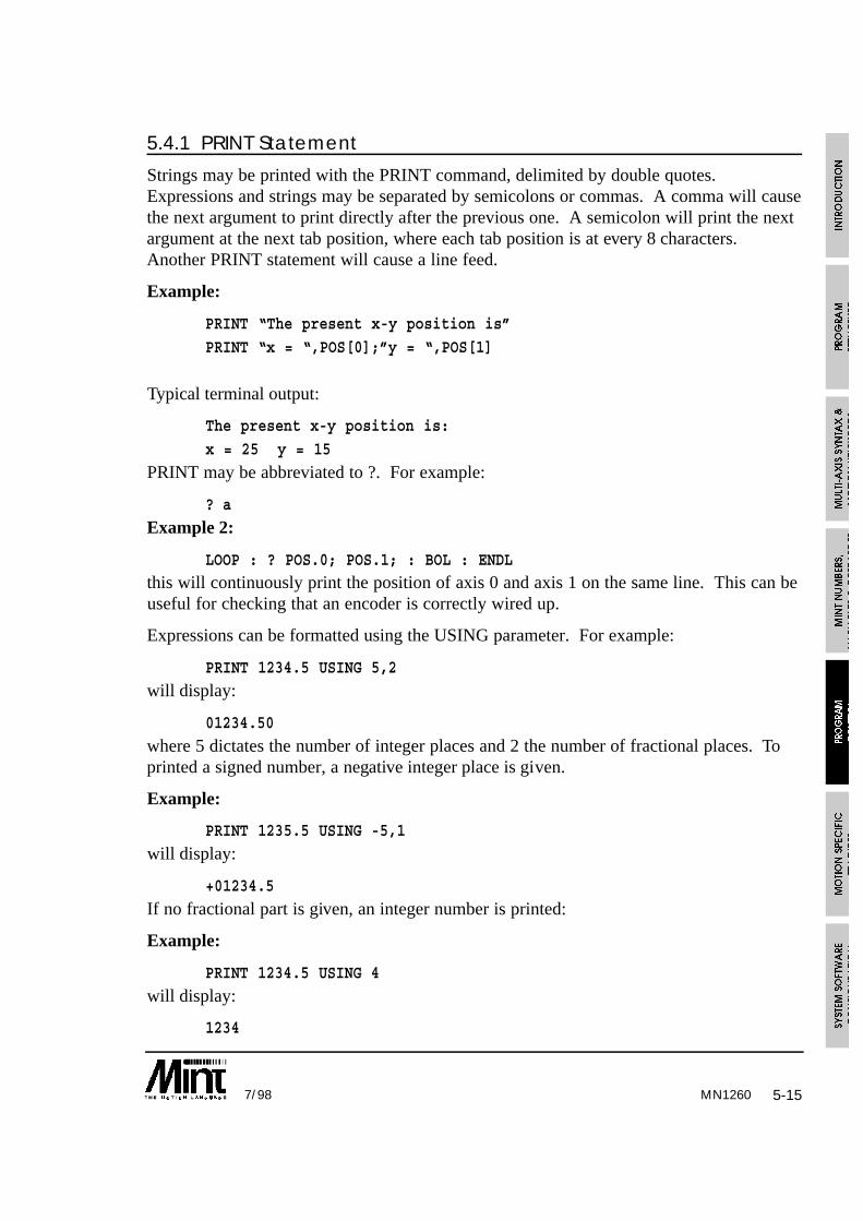
5-157/98
5.4.1 PRINT Statement
Strings may be printed with the PRINT command, delimited by double quotes.Expressions and strings may be separated by semicolons or commas. A comma will causethe next argument to print directly after the previous one. A semicolon will print the nextargument at the next tab position, where each tab position is at every 8 characters.Another PRINT statement will cause a line feed.
Example:
PRINT “The present x-y position is”
PRINT “x = “,POS[0];”y = “,POS[1]
Typical terminal output:
The present x-y position is:
x = 25 y = 15
PRINT may be abbreviated to ?. For example:
? a
Example 2:
LOOP : ? POS.0; POS.1; : BOL : ENDLthis will continuously print the position of axis 0 and axis 1 on the same line. This can beuseful for checking that an encoder is correctly wired up.
Expressions can be formatted using the USING parameter. For example:
PRINT 1234.5 USING 5,2
will display:
01234.50
where 5 dictates the number of integer places and 2 the number of fractional places. Toprinted a signed number, a negative integer place is given.
Example:
PRINT 1235.5 USING -5,1
will display:
+01234.5
If no fractional part is given, an integer number is printed:
Example:
PRINT 1234.5 USING 4
will display:
1234
MN1260

5-16 7/98
this is the same as:
PRINT INT(1234.5)
The LINE keyword is the same as PRINT but will display a string at the specified line.This is used for the standard keypad and display and will clear all characters to the end ofthe line. For example:
LINE 2, “A = “, A USING 3,2will print the value of A at line 2 using formatted output. The remaining 11 characters onthe display will be cleared.
The keyword BINARY works like PRINT, except an 8 bit number is printed in its binaryrepresentation. Negative numbers are printed in their two’s complement form.
Example:
BINARY “7 in binary is: “, 7
will display:
7 in binary is 00000111
5.4.2 INPUT Statement
INPUT is similar to standard Basic input supporting an optional string, followed by acomma, then a variable name. For example:
INPUT “Enter a number”,a
Terminal output:
Enter a number ?Only numeric input is accepted, any other characters are ignored. If the input string isinvalid the user will be requested to re-enter the number. Pressing return on an empty linewill retain the variable value. Multiple inputs cannot be separated by commas on thesame line as with most Basics.
Input can be formatted using the USING parameter:
INPUT a USING 5,2
will accept input with 5 integer places and 2 fractional places and no sign. Pressingdecimal dot will move the cursor to the number immediately after the decimal place.
Example 2:
INPUT a USING -5,2
will accept input with 5 integer places and 2 fractional places. The input can also besigned. Pressing ‘-’ will toggle the sign of the input value.
MN1260

5-177/98
Example 3:
INPUT “Enter new pos”, newPos USING 4
will allow a number to be entered with 4 integer places but no fractional places.
5.5 Keypad and Display
The keypad and operator terminal provide ageneral purpose operator terminal suitablefor stand alone machines of all types. Theoperator terminal is cost effective for simplefunctions, such as replacing thumb wheelswitches and providing simple diagnostics,or may be used as a fully interactiveprogramming panel for special purposemachine control. The user interface iswritten in MINT, an example of which isgiven in the Getting Started Guide.
The keypad interface board (standard on 3 axis servo controllers) allows Hitachi LCDdisplays or compatible units to be driven from the controller directly. The board alsoprovides connection for up to 64 keys arranged on an 8 by 8 matrix using normally openswitches. MINT allows you to define the value of each key in the matrix using a keywordKEYS, which means that the physical order of connection is not important.
Alphanumeric LCD displays of up to 40 characters by 2 lines or 20 by 4 lines may beused. Direct ribbon cable connection between the interface board and many populardisplays is possible
A piezoelectric buzzer is attached to the board via three flying leads. A short beep (usingthe BEEP keyword) can be used to acknowledge a key press, while a series of beeps canbe used to attract operator attention. The high pitch of the buzzer makes it audible overgeneral industrial noise from machinery.
5.5.1 Programming the Keypad and Display
MINT software supports the keypad and display as if it were a standard serial terminal.MINT statements PRINT, INPUT, CLS, LOCATE etc. can be used with the display, BEEPactivates the buzzer. Key presses cause characters to be placed in the serial port buffer sothat they can be read as normal by INKEY and INPUT. The READKEY function returnsthe value of the key that is currently pressed. This is an enhancement not normallyavailable on serial terminals and is very useful for jogging motors when the operator holdshis finger on a key.
MN1260

The keypad and display supports the following terminal I/O keywords:
Keyword Description
BEEP Sound the buzzer
BEEPON Sound buzzer when using INPUT
BEEPOFF Do not sound buzzer on INPUT
BINARY Print a binary number
BOL Send cursor to beginning of line
CLS Clear screen
INKEY Read a key from the serial port buffer
INPUT BASIC formatted input
KEYS Define layout of keyboard
LINE Formatted print to a specified line
LOCATE Locate cursor at column, row
PRINT BASIC formatted print
READKEY Read value of key currently pressed
TERM Direct output to LCD or serial port
The keypad interface makes it easy to build your ownoperator panel, using push buttons and a display, which isexactly suited to your application. Should you require acustom keypad then contact your distributor for details.
The operator panel incorporates six function keys placedabove and below the display, so that the function of each keycan be indicated by printing a legend on the top and bottomlines of the display. This allows menu driven operatorinterfaces to be written readily, with the function of each
function key changing depending on the menu. The middle two lines are used formessages or operator prompts.
Care must be taken when writing to the LCD display since the display does notscroll. If the last character of the display is written to followed by a carriagereturn, the entire display will be cleared. Use a comma at the end of a print
statement to suppress line feeding.
5-18 7/98MN1260

5-197/98
Example:
KEYS “”
LOOPLINE 1, “ EXIT”
LINE 2, “Sample keypad”
LINE 3, “Program”
LINE 4, “SETUP START MANUAL”,
key = 0REPEAT
key = INKEY
IF key = ‘A’ THEN BEEP: GOSUB setup
IF key = ‘B’ THEN BEEP: GOSUB startIF key = ‘C’ THEN BEEP: GOSUB manual
IF key = ‘F’ THEN BEEP: END
UNTIL key <> 0
ENDL
#start
REM Code here
RETURN
#start
REM Code here
RETURN
#manual
REM Code here
RETURN
Note the use of BEEP to provide audible feedback to the operator. BEEPON can also beused for this purpose. Also note the comma at the end of LINE 4 statement. This is usedto suppress line feeding and clearing the screen.
The KEYS statement at the beginning of the program is used to enable the keypad. If acustom keypad is used, the KEYS keyword is used to define the actual keys on thekeypad. See section 10 for further details.
Using the keypad interface, it is possible to read the currently pressed key usingREADKEY. This is unlike INKEY which returns the next keypress in the serial inputbuffer. READKEY is useful for jogging motors while a key is pressed.
MN1260

5-20 7/98
Example:
LOOP
IF READKEY = ‘X’ THEN JOG[0] = 10IF READKEY = ‘U’ THEN JOG[0] = -10
IF READKEY = 0 THEN JOG[0] = 0
ENDL
using the X left and right keys on the keypad, the motor will be jogged left or right whilethe key is pressed. When either of the keys are released (READKEY = 0) the motor willcome to a stop.
5.6 Sending Data to an Executing Program
MINT provides two methods of accepting data to an executing program:
• INPUT or INKEY can be used to read the serial port buffer or from the keypad.
• A protected protocol that allows the host computer to read and write data from/to apre-defined array variable.
5.6.1 Serial Port/Keypad Buffer
Characters received by the serial port are stored in a 128 character circular buffer untilthey are read by MINT. Use of this buffer is totally transparent to the user during normalprinting and input routines in MINT.
The buffer enables you to send information to a card at any time for use in a MINTprogram running on board.
By default, MINT receives data from both the keypad and the serial port. To switchbetween the 2, use the TERM keyword. For example:
TERM = _lcd
will direct all terminal I/O to the keypad and lcd display only. Note that Ctrl-E can beused to restore the terminal I/O state back to the serial port.
MN1260

5-217/98
5.6.2 Reading Data from the Serial Buffer using INKEY
Data may be extracted from the serial buffer by the use of INKEY or INPUT keywords.
INKEY is used to read a single character from the buffer. IF no character is present it willreturn zero, otherwise it returns the ASCII value of the character. (ASCII is aninternational standard defining binary equivalents to alphanumeric characters).
INKEY always returns the uppercase value of the characters A-Z. Thus:
MY_VAR = INKEY
will return the value 65 (the ASCII value of ‘A’) to the variable MY_VAR if the character‘A’ or ‘a’is present in the buffer.
You can test the value of MY_VAR using a simple IF statement as shown:
IF MY_VAR = 65 THEN PRINT “A received”
an alternative notation, that does not require knowledge of ASCII values is:
IF MY_VAR = ‘A’ THEN PRINT “A received”
Where the character A is enclosed in single quotes to inform MINT that it’s ASCIIrepresentation should be used.
INPUT can be used to read numeric values from the character buffer into MINT variables.A numeric value is sent down the serial link as its ASCII representation, terminated by acarriage return (ASCII 13 decimal). For instance to send the value 123.45 you wouldsend:
123.45
One very important difference between INKEY and INPUT is that INKEY does not stopprogram execution. It simply returns a zero if there is no data in the buffer and istherefore useful for testing if there is data in the buffer. INPUT will wait until it receivesa valid ASCII number terminated by a carriage return.
The following code section shows how INKEY can be used to clear the serial port:
PAUSE INKEY = 0
Example:
The following simple example programs are designed to illustrate the use of INKEY andINPUT using a terminal emulator program such as cTERM which is included with thecontroller.
The program below is a very simple example showing the use of INKEY. It simply loopsaround waiting for a character to be received (i.e. a non zero value) and then prints theASCII value of the received character. Note use of a question mark, the abbreviation forthe keyword PRINT.
MN1260

5-22 7/98
LOOPa = INKEY
IF a <> 0 THEN ? a
ENDL
The second example is more complex, it waits for ‘a’ or ‘r’ to be received and then acceptsdata which is printed back to the user. In a typical application, this data might be used toperform a MOVEA or MOVER depending on the data received.
LOOP : REM infinite loop
REM wait until a key is pressed
REPEAT : key = INKEY : UNTIL key <> 0
REM read dataIF key = ‘a’ THEN INPUT var1 : ? “a selected, value is “,var1
IF key = ‘r’ THEN INPUT var2 : ? “r selected, value is “,var2
ENDL
Note the use of the variable key to store the keypress before it is tested.
The READKEY keyword is in conjunction with the keypad option to return the value ofthe currently pressed key. Unlike INKEY which returns the next character in the serialport buffer, READKEY will return the key value while the key is pressed, and zero whenno key is pressed.
Example:
LOOP
temp = INKEY : REM Clear the serial port bufferIF READKEY = ‘A’ THEN JOG = 1
IF READKEY = ‘B’ THEN JOG = -1
IF READKEY = 0 THEN JOG = 0
ENDL
will jog the motor in a positive direction only while the key ‘A’ is pressed. The motor isjogged in a negative direction only while ‘B’ is pressed.
MN1260

5-237/98
5.6.3 Host Computer Protected ProtocolMINT provides a protected protocol toallow the interchange of data between ahost computer and MINT via an arrayvariable COMMS, which is 99 locationsin length. Data packets are sent from thehost to either place data into one of these99 locations or to read a location. TheMINT program can read the arrayvariable and act on the data accordingly.
Example:
COMMSON
LOOP
IF POS > COMMS(1) THEN JOG = -10IF POS < COMMS(2) THEN JOG = 10
COMMS(3) = POS
ENDL
this example will jog between two end points set by the host computer. The position isstored in location 3 and can be read by the host.
Example 2:
COMMSONcomms(1) = 0
LOOP
command = comms(1)
IF command <> 0 DOIF command = 1 THEN SP.1 = comms(2):MOVEA.1 = comms(3):GO.1:PAUSE IDLE.1
IF command = 2 THEN SP.1 = comms(2):MOVER.1 = comms(3):GO.1:PAUSE IDLE.1
IF command = 3 THEN HM.1 = comms(4):PAUSE IDLE.1
ENDIFcomms(1) = 0 : REM Send Ack back to host
ENDL
In this example, the host will transmit a command in comms(1). The data for the movetype is held in indexes 2 to 4. When the moves is complete, the command is set to zero.This acts as an acknowledgement to the host.
MN1260

5-24 7/98
The COMMSON keyword activates the protected communication and defines the commsarray. Ctrl-E will be disabled and can only be enabled using a special data packet sent bythe host. If cTERM for DOS is used, pressing Shift-F8 will abort protectedcommunications.
The communications protocol is explained in detail in section 12.
MN1260

6-17/98
6. Motion Specific FeaturesThis section deals with the different modes of motion.
6.1 Torque ControlServo Axes Only
Torque control is achieved by controlling the current in the motor armature. For thispurpose the amplifier must be configured as a current amplifier i.e. the analog demandinput to the amplifier relates directly to an output current. Motor torque is directly relatedto current by the expression:
Torque = Armature Current * Kt
where Kt is the motor torque constant. The armature current will depend on the peak andcontinuous rating of the amplifier.
TORQUE will accept any value between -100.0 and +100.0. Where the maximumcorresponds to the peak current from the drive. For example, for a drive with 20A peakcurrent rating:
TORQUE = -50Sets the motor current equal to -10A, i.e. 50% of the peak current. Note that settingtorque to 100% will cause the amplifier to deliver peak current continuously, which maycause it to burn out.
Torque is terminated by the STOP command which puts the controller back into astationary positional control mode. This will cause a moving motor to instantly stop. Toavoid jarring the motor, it is recommended that the motor armature is stationary beforeSTOP is executed. This can be done with a loop:
FOR a = 50 to 1 STEP -1
TQ = a
WAIT = 50NEXT
STOP
where TQ is the abbreviated keyword for TORQUE.
You can freely change between torque, positional and speed control as the applicationdemands however you must make sure an axis is idle first. For example:
TQ = 10
WT = 1000
MOVEA = 100 : GO
MN1260
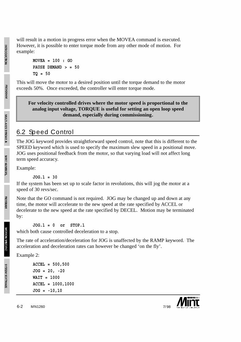
6-2 7/98
will result in a motion in progress error when the MOVEA command is executed.However, it is possible to enter torque mode from any other mode of motion. Forexample:
MOVEA = 100 : GO
PAUSE DEMAND > = 50TQ = 50
This will move the motor to a desired position until the torque demand to the motorexceeds 50%. Once exceeded, the controller will enter torque mode.
For velocity controlled drives where the motor speed is proportional to theanalog input voltage, TORQUE is useful for setting an open loop speed
demand, especially during commissioning.
6.2 Speed ControlThe JOG keyword provides straightforward speed control, note that this is different to theSPEED keyword which is used to specify the maximum slew speed in a positional move.JOG uses positional feedback from the motor, so that varying load will not affect longterm speed accuracy.
Example:
JOG.1 = 30
If the system has been set up to scale factor in revolutions, this will jog the motor at aspeed of 30 revs/sec.
Note that the GO command is not required. JOG may be changed up and down at anytime, the motor will accelerate to the new speed at the rate specified by ACCEL ordecelerate to the new speed at the rate specified by DECEL. Motion may be terminatedby:
JOG.1 = 0 or STOP.1which both cause controlled deceleration to a stop.
The rate of acceleration/deceleration for JOG is unaffected by the RAMP keyword. Theacceleration and deceleration rates can however be changed ‘on the fly’.
Example 2:
ACCEL = 500,500
JOG = 20, -20
WAIT = 1000ACCEL = 1000,1000
JOG = -10,10
MN1260

6-37/98
jogs axis 0 at 20 and axis 1 at -20, wait 1 second and then jog at -10,10, ramping to thenew speed at the new acceleration of 1000.
A JOG motion can be executed at any time regardless of the current motion on the axis.The axis will either accelerate or decelerate from its present speed to the new definedspeed set by JOG. This allows blended motion, from say a positional move to a speedcontrolled move. For example:
MOVEA = 0 : GO
PAUSE IN1JOG = -100
6.3 Positional ControlPositional control functions include:
• Simple single axis positional control (MOVEA/MOVER)
• Two/three axis linear interpolation (VECTORA/VECTORR)
• Two axis circular interpolation (CIRCLEA/CIRCLER)
which are available in both absolute and relative co-ordinates.
Additional positional control is available in Process MINT, in the form of:
• Cam profiling
• Flying shears
6.3.1 Linear Positional ControlIn the basic linear positional control mode the keywords MOVEA and MOVER providerespectively absolute and incremental position control.
MOVEA = 200 : GO
Will cause the controller to move the axis to an absolute position of 200 counts from zero.
MOVER = 100 : GO
Will move the axis a further 100 counts relative to the current position, making 300absolute. Hence the command:
PRINT POS
Will return 300 as the current axis position (assuming zero error). This is shown in thediagram:
MN1260

6-4 7/98
Notes
• Reading the OFFSET keywordwill return the remaining vectorlength, i.e. how far the axis mustmove before coming to a stop.
• Reading MOVEA or MOVERwill return the absolute endposition of the move in progress.Therefore reading MOVEA forthe previous example will return300.
The GO keyword is used to initiate motion after the distance for the move has been set up.This allows different multi axis moves to be synchronized:
MOVEA[1] = 30MOVER[0] = 40
GO[0,1]
will start axes zero and one together.
During a positional move, the end point of the move can be altered using the INCA andINCR keywords, standing for increment absolute and increment relative. INCA will set anew end position in absolute co-ordinates. INCR will set the new end position relative tothe current end position of the move in progress (the current end position can be readusing the MOVEA or MOVER keywords).
Example 1:
On seeing an input, we want to set a new position of the current move equal to the currentposition plus a relative distance of 10.
PAUSE IN0 : REM Wait for the inputINCA = POS + 10
PAUSE IDLE
Example 2:
In a one axis rolling feed system, a second encoder, on axis 1, is used to detect slip.When the material is near the end of its move, we want to check for slip and correct for it.
PAUSE POS < nearEndPosINCR = POS.0 - POS.1
PAUSE IDLE
MN1260

6-57/98
To use the above example, axis 1 must be put into either SERVOFF.1 (servo off) mode orturned off using CONFIG.1 = _off. This enables the encoder to read but not to generate afollowing error.
INCA and INCR cannot be used to change the end position of interpolated moves.
Reading the OFFSET keyword during a positional move will return the remaining movelength. For example:
MR = 200 : GO.0
? OFFSET
will return 200 i.e. the length of the move in operation.
MR = 200 : GO.0
PAUSE POS >= 170
? OFFSETwill return a value of approximately 30. Note that OFFSET always returns a positivenumber regardless of the direction of motion.
The OFFSET keyword is useful in indexing applications to determine how much of theindex is remaining. For example: in an indexing application, an output must be set 30mmbefore the end of the move where each index is 100mm in length:
LOOP
MOVER.1 = 100 : GO.1
PAUSE OFFSET.1 <= 30 : REM Wait for 30mm before endOUT1 = 1 : REM Set output
PAUSE IDLE.1 : REM Wait to stop
OUT1 = 0 : REM Clear output
ENDL
6.3.2 Interpolated Moves
The VECTORR/VECTORA and CIRCLER/CIRCLEA keywords provide interpolatedmotion on two/three orthogonal axes, for instance an X-Y table. These keywords arewrite only motion variables but are unique in that they always require at least two axes tobe specified. In interpolated moves, the axis speed and acceleration refer not to individualaxis speed, but to the path along which motion is in progress. Before initiating the move,it is important to ensure that the speed (SPEED), acceleration (ACCEL) and ramp factor(RAMP) on both axes are the same in terms of quad counts or steps and not scaled units(millimeters for example). This ensures that the velocity profiles on all axes stop at the
MN1260

6-6 7/98
same time (see section 6.3.5) Both axes should have the same line count/step rate forcorrect operation. For example:
SCALE = 100,200
SPEED = 20,20ACCEL = 1000,1000
the speed and acceleration are not the same in terms of quad counts or steps due to thescale factor.
SCALE = 100,200
SPEED = 40,20ACCEL = 2000,1000
is correct.
Note:
• Circular interpolation can only be performed on the first 2 axes (axes 0 and 1) of thecontroller.
• Both axes must have the same gear ratio and encoder line count for correct operation.In the case of circles, a gear ratio of 2:1 between X and Y for example will result in anellipse with an aspect ratio of 2:1. A circle cannot be drawn with different gear ratioson the motors.
6.3.3 Linear Interpolation
Two/three axis linear interpolation is executed with the keywords VECTORR andVECTORA, where VECTORR is a relative vector move, and VECTORA is an absolutevector move.
Example:
AXES[0,1]SPEED = 20;
VECTORA = 30,40 : GO
Executes an absolute linear interpolated move on orthogonal axes 0 and 1 at a speed of 20along the vector. After the AXES string and SPEED is set up, further moves require justthe VECTORR/VECTORA.
This differs from the command MOVEA:
SPEED = 20;MOVEA = 30,40 : GO
MN1260

6-77/98
this will give the same absolute end position but the speed will be 20 on each axis, so axis2 will reach its end point before axis 3.
The above examples make use of the semicolon to set the speed of both axes equal to 20.Thus:
SPEED = 20;
SPEED = 20,20
are the same.
Example 2:
VECTORR = 100,200,300 : GO
this performs a 3 axes relativeinterpolated move.
Example 3:
assuming a starting position of 0,0 theabove can be generated using thefollowing relative moves:
VR = 20,25 : GOVR = 20,15 : GO
VR = 40,-15 : GO
VR = 0,-15 : GO
The same moves can be generated using the following absolute co-ordinates:
VA = 20,25 : GO
VA = 40,40 : GO
VA = 80,25 : GO
VA = 80,10 : GO
The final position of a vector move can be read using theMOVEA or MOVER keywords.
See section 6.3.2.
MN1260

6-8 7/98
6.3.4 Circular Interpolation3
Interpolation MINT only.
A circular arc between axes 0 and 1 of the system can be performed by use of theCIRCLEA or CIRCLER keywords.
The format for circular interpolation is:
CIRCLER[axis0,axis1] = <centre0>,<center1>,<angle>
<centre0>, <centre1> sets up the centre for motion on this circular axis relative to thecurrent position, the radius of curvature is the distance from the centre of motion to thecurrent axis position. <angle> (+/-360.00 degrees) sets up the angular increment for thecircular arc. Positive numbers refer to anti-clockwise motion.
CIRCLEA[axis0,axis1] = <centre0>,<center1>,<angle>Sets up an absolute circular move where <centre0> and <centre1> are absolute co-ordinates.
The final position of a circular move can be read using theMOVEA or MOVER keywords.
Example:
Assuming a starting position of 30,30, the circle can be generated using:
CA = 20,20,180 : GO : REM Absolute Coords
Or:
CR = -10,-10,180 : GO : REM Relative Coords
The major difference betweeninterpolated positional motion and simplesingle axis position control as statedpreviously is that RAMP, SPEED andACCEL apply not to individual axes, butto the path along which the X-Y axes ofmotion follow. By combining a series ofinterpolated moves in an X-Y tableapplication a complex path formed fromarcs and straight line segments may beconstructed.
See section 6.3.2.
MN1260
3Interpolation MINT only

6-97/98
6.3.5 Velocity Profile
In a positional move the velocity profile may be trapezoidal or ‘S’ shaped. See the figure.Trapezoidal ramps provide the fastest point-to-point time for a given motor torque, but ‘S’shaped ramps provide smoother motion with the disadvantage of longer motion times.
In order to give short,smooth moves, MINTimplements a modified ‘S’ramp, where theacceleration increasesrapidly, but tails off moreslowly to provide a smoothapproach to top speed orfinal position. The keywordRAMP determines thesmoothness of the profile,where 0 is a trapezoidalprofile, and 10 is a veryrounded profile.
The acceleration rate iscontrolled with the keyword ACCEL, deceleration rate by DECEL and the maximum slewspeed is controlled by SPEED. If the positional move is so short that the specifiedSPEED cannot be attained a triangular velocity profile will result.
SPEED can be changed up and down during a move and the controller will accelerate ordecelerate to the new speed at the specified rate. The acceleration and deceleration ratescan also be altered on the fly. However, the deceleration rate is altered on the fly, ifnecessary, in order to stop at the desired end position.
6.3.6 Move Buffer and GO
MINT is a powerful language for motion control allowing simultaneous motion and Input/-Output or other functions such as waiting for the motor speed to reach a given speed beforestarting motion on other axes. This is because MINT only stops program execution when itcan no longer process any more program lines without interrupting a move in progress.
Consider the following code fragment, which shows two absolute moves, the first toposition 10 and the second to position 20:
MOVEA = 10
GOMOVEA = 20
GO
MN1260

6-10 7/98
MINT will encounter the first statement and immediately execute it, followed by GOwhich will start the move. (GO is used to start all positional moves). MINT nowencounters the next move statement and will set it up as the move pending on that axis.When MINT encounters the next GO statement it will identify that a move is already inprogress on the axis and wait, at this point therefore program execution will stop.
You can see that MINT is always one step ahead of the actual move in progress. Thisallows you to start a move on one axis and then execute other statements that might lookat inputs or execute other moves on other axes that start at a specified delay after the firstmove.
For example:
MOVEA = 100 : GO
PAUSE VEL > 20OUT1 = 1
will start a move on the axis and then wait until the velocity of that axis is greater than 20.After this is true then the program sets digital output one.
It is important that you should understand this concept because it is fundamental towriting MINT programs. There are some motion commands that are only valid when theaxis is not moving (in IDLE mode), these restrictions are noted against the specifickeywords in Section 10. For instance, acceleration cannot be adjusted during a positionalmove, therefore the code fragment:
MOVEA = 100 : GOACCEL = 200
will cause the program to abort with an error message:
ERROR: Motion in progress at line xx.
6.3.7 Contoured Moves
The keyword CONTON (Contouring On) allows a series of interpolated moves to beexecuted without decelerating at the end of each positional move. Thus the path is tracedout at a constant rate of motion.
Example:
SPEED = 20,20
CONTON
VECTORR = 40,40 : GOCIRCLER = 20,-20,-90 : GO
PAUSE IDLE[0,1] : REM Wait for axes to stop before
CONTOFF : REM Turning contouring off
MN1260

6-117/98
Assuming a starting position of 40,-20,this executes a straight line segment onaxes 0 and 1 followed by a circular arc of90 degrees at constant speed of 20. Notethat it is imperative to set the axis speedsand accelerations to the same value beforeexecuting the move since these refer tospeeds and accelerations along the vectorof motion.
The contouring routines maintain aconstant vector speed throughout the profile, deceleration will not occur until MINTdetects that the final vector has been reached. This gives rise to the following constraints:
• The speed must be low enough for the total deceleration phase to fit into the finalvector - otherwise the axes will come to an abrupt stop.
• Contouring should only be attempted around smooth shapes. Corners should berounded, a right angled corner will jar the machine since one axis mustinstantaneously stop and the other instantaneously start.
Contoured moves apply to the card as a whole. It is not possible to set-upcontoured moves on 2 axes and a normal positional move on the third axis.
Only the 2 axis contoured move can be executed.
6.4 Establishing a Datum
The HOME keyword is used to establish a datum position on the axis. This function isuseful for all applications that require a consistent zero point from which moves arereferenced. The HOME function should be incorporated at the beginning of the program,or in the configuration file. There are a number of alternative methods of establishing adatum that must be considered at the system design stage:
• In many applications (e.g. a linear table) the zero position may be defined by a limitswitch on the axis end stop or by a separate dedicated home switch that is placed at acentral point on the slide. If homing is to be performed on a limit switch, then thehome input must be connected to the limit input (see the hardware manual).
• The home position can be established on the basis of the opening of contacts on ahome switch, or on the first index pulse of the encoder after opening of the switch.The first method is quicker but less accurate than the second. However, the secondmethod requires a three channel encoder, with a separate marker (index) pulse.
MN1260

6-12 7/98MN1260
• With the controller, homing is always performed on the basis of a transition on thehome switch input from closed (connected to ground) to open circuit. For correctfunction of the HOME routine you must ensure that the home input is closed circuitwhen the function is called. Otherwise, the homing routine will immediatelyterminate.
6.4.1 Home Control WordThe use of an index pulse and direction of seek (positive or negative) that the systemmoves to find home is controlled by assigning a number to the homing routine as follows:
HOME[axes] = <home_control> {,<home_control> ...}
Where <home_control> is a binary number where bit zero, the least significant bit,determines index pulse usage and bit 1 determines positive or negative slew direction andbit 2 determines whether to home on the index pulse only for a rotary system. The binarynotation is shown in the table:
Home Control Word
Bit Number Action
0 1 to datum on home switch and seek index
1 1 to datum in a positive direction, 0 in a negative direction
2 1 to datum on the index pulse only
HOME values are:
Binary value Decimal Constant MeaningValue
0 0 _neg Negative seek, datum on switch
0001 1 _negindex Negative seek, datum on index
0010 2 _pos Positive seek, datum on switch
0011 3 _posindex Positive seek, datum on index
0100 4 4 Seek index pulse negative direction
0110 6 6 Seek index pulse positive direction
For instance, to perform homing on axis 1 in a positive direction with zero position as thefirst index pulse before limit switch closure, using binary notation:
HOME.1 = 011

6-137/98
Usually a homing sequence is followed by PAUSE IDLE to ensure all axes are at theirdatum position before continuing. For example:
HOME[0,1,2] = 0,0,0 : REM Datum axes
PAUSE IDLE[0,1,2] : REM Wait for idle...
Reading the HOME keyword will return the status of the home switch.
Some systems may have two datum positions, one to left and another to the right. Tomaintain the same absolute positions, the POS keyword can be used to set a position oncethe datum position has been set:
IF homeLeft DO
HOME = 1
PAUSE IDLEPOS = 0
ELSE
HOME = 3
PAUSE IDLEPOS = 10000
ENDIF
This will define one datum point as position 0 and the other as position 10000 counts.This also assumes that the two datum positions are 10000 counts apart.
6.4.2 Home Sequence
The HOME sequence is as follows
• The axis slews in the specified direction at a rate specified by the HMSPEED keyworduntil an open circuit is detected on the home input. HMSPEED should be set low fordatuming.
MN1260

6-14 7/98
• The axis reverses and creeps at HMSPEED/BACKOFF until the switch input closesagain. BACKOFF is a user definable parameter.
• If home_control is configured to perform datum on switch, the position counter isreset to zero and the routine terminates.
• Otherwise, for datum on index, the axis continues at HMSPEED/BACKOFF until itdetects a transition on the index pulse. The axis stops, but because of the speed oftravel it will invariably overshoot. Therefore, the axis reverses again and creeps veryslowly back until it sees a transition on the index pulse. The position counter is thenreset to zero and the routine terminates.
Example:
HMSPEED = 200,200,200BACKOFF = 5,5,5
HOME = 1,1,1
PAUSE IDLE[0,1,2]
will set a datuming speed of 200 units/sec. When the home switch is seen, the axis willbackoff at a speed of 40 units/sec. For most applications you can leave backoff at itsdefault value of 10.
Function of the homing routine is very dependent on correct system installation, referenceshould be made to the hardware reference guide before attempting to use this facility.Establishing which direction is positive often requires a little careful experimentationduring system commissioning. This can be done simply by moving the axis manuallybackwards and forwards and reading the position. The following code can be used to dothis:
LOOP : ? POS; : BOL : ENDL
6.4.3 Order of Datuming
In most applications both axes are homed simultaneously for speed. For instance:
HOME.0 = 3
HOME.1 = 3
or:
HOME[0,1] = 3,3
or:
HM = 3;
executes simultaneous homing in a positive direction, on switch, for axes 0 and 1assuming AXES[0,1].
MN1260

6-157/98
Alternatively:
HOME = _posindex,_posindex
can be used.
In some applications there may be a requirement to datum one axis before the other toavoid mechanical obstructions. In order to achieve this you must include a PAUSE IDLEcommand between the two HOME commands:
HOME.0 = 3 : REM home axis zeroPAUSE IDLE.0 : REM wait for homing to finish on 0
HOME.1 = 3 : REM home axis one
If the limit switches are open circuit at any time other than during homing the drive unitwill cease to function and report a limit switch closure error. This is indicated by an ‘L’on the front panel status display and by the ERROR keyword which will return 3.
6.4.4 Defining a New Position
After the datum routine is complete, the zero position may be offset by performing apositional move and executing the keyword ZERO. This keyword zeros the positioncounter and establishes the current position as the new axis position.
A suggested code fragment for this is:
HOME.0 = 0 : REM execute homing routine (on switch)
MOVEA.0 = 20000:GO.0 : REM desired new home
PAUSE IDLE.0 : REM wait for end of moveZERO.0 : REM new zero position
It may be necessary to set a new datum position without actually moving the motor. Thiscan be achieved by using the POS keyword to set the position. For example:
HOME.0 = 0 : REM execute homing routine (on switch)
PAUSE IDLE.0 : REM wait for end of movePOS.0 = 10000 : REM Set new datum position to 10000
6.5 Pulse FollowingThe controller has a pulse and direction input that can be used to follow an external pulsetrain using the PULSE keyword. Pulse following is useful for master/slave typeapplications, or where the drive is intended to replace a stepper system, taking input froma stepper controller. The format is:
PULSE[axes] = <scaling factor> {,<scaling factor> ...}
MN1260

6-16 7/98MN1260
where the <scaling factor> is a number that determines the gear ratio between the pulseinput and the axis. Note that there is always a natural ratio of 2:1 since the controllercounts both the rising and falling edges of the pulse input. The gear ratio will also dependon the line density of the encoder.
PULSE = 1
will produce a movement of 2 quadrature counts on the encoder for a single pulse input(single pulse has 2 edges).
When pulse following is initiated it will ramp up to the incoming pulse speed (read usingPULSEVEL) at an acceleration rate defined by ACCEL.
The pulse input has an associated direction input which causes the pulse counter to countup or down. In many applications where you are following a machine which does notreverse, the common practice is to connect just one channel of the master encoder to thepulse input, which gives 2x multiplication by counting both rising and falling edges. Thedirection input should also be tied to either 5V or ground. It is also possible to interfaceboth channels of an incremental encoder by using an external quadrature decoder chipsuch as a Hewlett Packard 2016. This converts the A and B channels into a pulse anddirection signal. MINT also allows direct encoder following via one of the controllersencoder inputs. This is discussed in section 6.6.
Pulse following mode is terminated by the STOP command or by assigning 0 to PULSE.
Example 2:
PULSE = 2.5, -1will produce a movement of 5 counts on the motor for a single pulse input on the firstaxis, and a movement of 2 counts per pulse input on the second axis but in the oppositedirection.
There are various keywords associated with pulse following. These are:
Keyword Action
OFFSET/OF Perform an offset on the base speed
PULSEVEL/PV Velocity of pulse train
TIMER/TI Read timer (pulse follower input)
WRAP/WR Set reset value of timer
Using the reset counter input on the controller, a marker pulse on an encoder can be usedto reset the internal pulse timer every revolution of the encoder. The maximum number ofcounts received from the encoder will therefore be:
line count x 2

6-177/98
hence, for a 1000 line encoder, the TIMER keyword which is used to read the number ofpulses received, will return a maximum value of 2000. The WRAP keyword must be setto a value of 2000 to notify MINT that the timer is reset every 2000 counts.
The OFFSET keyword is used to perform a positional offset on the base speed duringpulse following. This can be shown in the following example:
Example:
PULSE = 1
WAIT = 1000 : REM Wait to get up to speedOFFSET = 10 : REM move forward 10
PAUSE MODE = _pulse
OFFSET = -10 : REM Move back 10
These keywords are used in infeed systems and are explained in detail in section 10. Anexample of an infeed system is given in the Getting Started Guide.
Using FOLLOW and FOLLOWAXIS, it is possible to position lock the slave axis to thepulse input. See section 6.6 for details.
6.6 Encoder Following/Software GearboxIn addition to pulse following, the servo controller also has an encoder following mode.Using the FOLLOW keyword in conjunction with the FOLLOWAXIS keyword, any axison the system can follow any other axis.
Example:
FOLLOWAXIS.0 = 2
FOLLOW.0 = -2
MN1260

6-18 7/98
will set up axis 0 to follow the encoder on axis 2. Axis 0 will then follow at a ratio of 2:1but in the opposite direction.
Using the previous example, power can be applied to axis 2 and positional moves or speedcontrol performed on the axis. In this case, axis 0 will follow axis twos movement with a2:1 ratio. However, it may be that an external encoder must be followed. In order to dothis, the encoder to follow must have its axis turned off. For example:
CONFIG.2 = _off
FOLLOWAXIS[0,1] = 2,2FOLLOW[0,1] = 1.5,-1.5
both axes 0 and 1 will follow an external encoder with a gear ratio of 1.5:1. Axis 1 willfollow in the opposite direction.
FOLLOW will not ramp up to theincoming encoder speed but will lock
onto it directly at the given ratio.This can cause systems to jump.
During follow mode, an OFFSET can beperformed on the following axis. Forexample:
FOLLOW = 1WAIT = 1000 :REM Wait to get up to speed
OFFSET = 10 :REM move forward 10
PAUSE MODE = _follow
OFFSET = -10:REM Move back 10
An application, using FOLLOW, is discussed in the Getting Started Guide.
6.6.1 Clutch DistanceProcess MINT supports a defined acceleration and deceleration (clutch) distance on theslave. This is configured using the MASTERINC keyword. For example:
SCALE = 1,1 : REM Scale in counts
FOLLOWAXIS.0 = 1MASTERINC.0 = 1000 : REM Acceleration distance
FOLLOW.0 = 1 : REM 1:1 ratio
PAUSE !IN1 : REM Wait for input
MASTERINC.0 = 2000 : REM Change deceleration distanceSTOP.0 : STOP following
MN1260
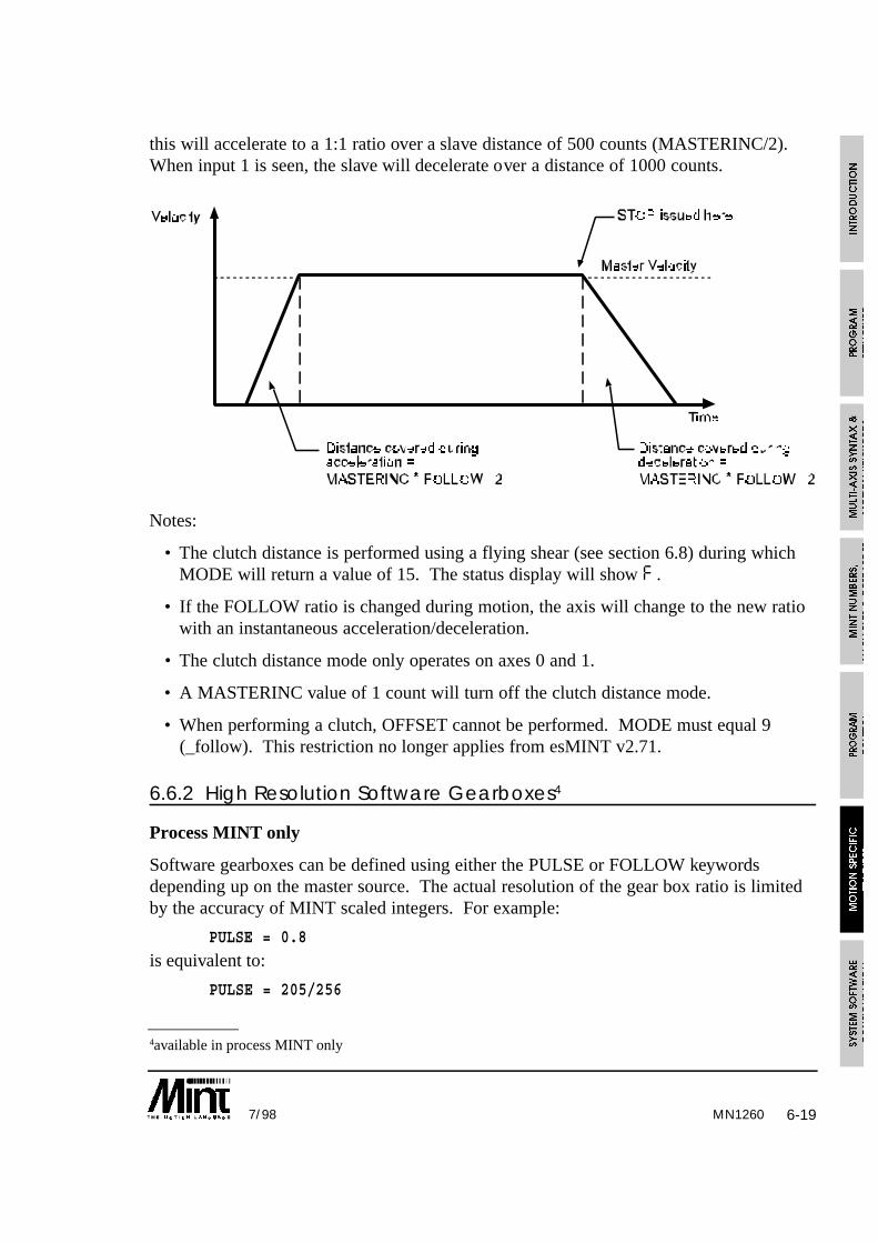
6-197/98
this will accelerate to a 1:1 ratio over a slave distance of 500 counts (MASTERINC/2).When input 1 is seen, the slave will decelerate over a distance of 1000 counts.
Notes:
• The clutch distance is performed using a flying shear (see section 6.8) during whichMODE will return a value of 15. The status display will show F .
• If the FOLLOW ratio is changed during motion, the axis will change to the new ratiowith an instantaneous acceleration/deceleration.
• The clutch distance mode only operates on axes 0 and 1.
• A MASTERINC value of 1 count will turn off the clutch distance mode.
• When performing a clutch, OFFSET cannot be performed. MODE must equal 9(_follow). This restriction no longer applies from esMINT v2.71.
6.6.2 High Resolution Software Gearboxes4
Process MINT only
Software gearboxes can be defined using either the PULSE or FOLLOW keywordsdepending up on the master source. The actual resolution of the gear box ratio is limitedby the accuracy of MINT scaled integers. For example:
PULSE = 0.8
is equivalent to:
PULSE = 205/256
MN1260
4available in process MINT only
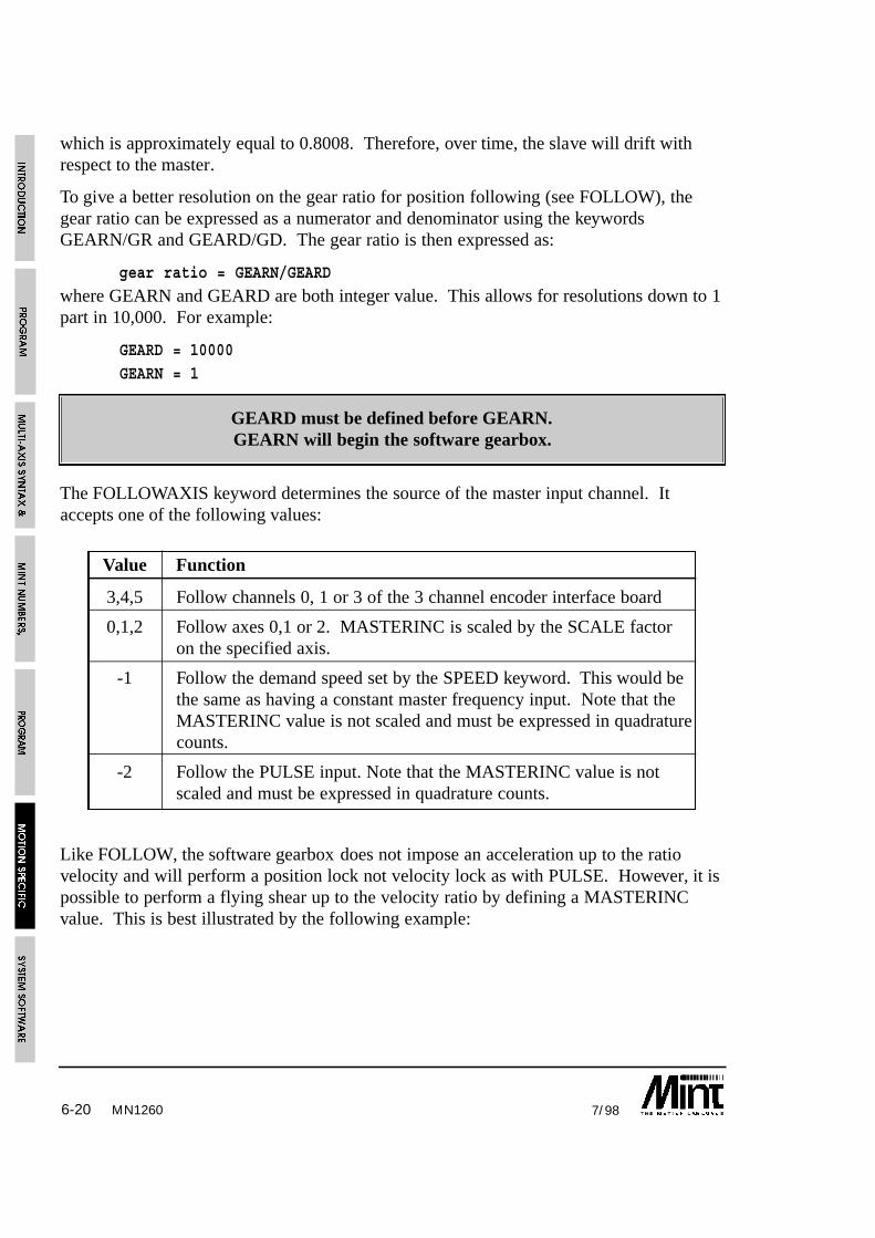
6-20 7/98
which is approximately equal to 0.8008. Therefore, over time, the slave will drift withrespect to the master.
To give a better resolution on the gear ratio for position following (see FOLLOW), thegear ratio can be expressed as a numerator and denominator using the keywordsGEARN/GR and GEARD/GD. The gear ratio is then expressed as:
gear ratio = GEARN/GEARD
where GEARN and GEARD are both integer value. This allows for resolutions down to 1part in 10,000. For example:
GEARD = 10000GEARN = 1
GEARD must be defined before GEARN.GEARN will begin the software gearbox.
The FOLLOWAXIS keyword determines the source of the master input channel. Itaccepts one of the following values:
Value Function
3,4,5 Follow channels 0, 1 or 3 of the 3 channel encoder interface board
0,1,2 Follow axes 0,1 or 2. MASTERINC is scaled by the SCALE factoron the specified axis.
-1 Follow the demand speed set by the SPEED keyword. This would bethe same as having a constant master frequency input. Note that theMASTERINC value is not scaled and must be expressed in quadraturecounts.
-2 Follow the PULSE input. Note that the MASTERINC value is notscaled and must be expressed in quadrature counts.
Like FOLLOW, the software gearbox does not impose an acceleration up to the ratiovelocity and will perform a position lock not velocity lock as with PULSE. However, it ispossible to perform a flying shear up to the velocity ratio by defining a MASTERINCvalue. This is best illustrated by the following example:
MN1260
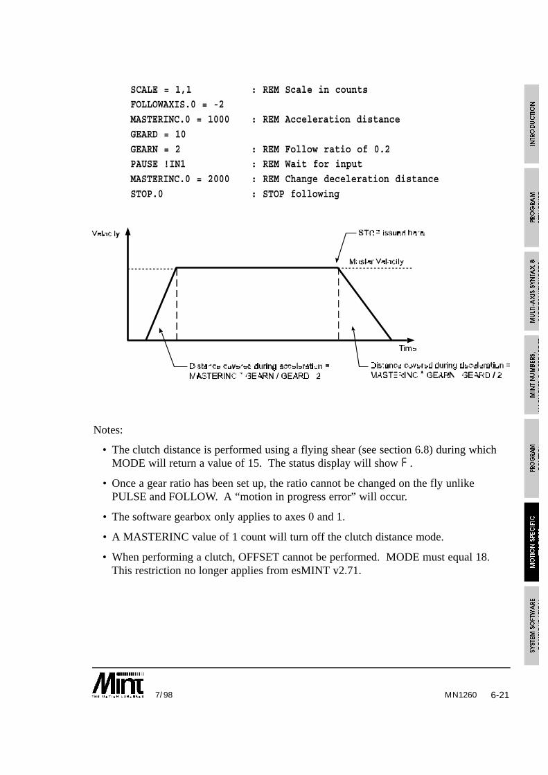
6-217/98
SCALE = 1,1 : REM Scale in countsFOLLOWAXIS.0 = -2
MASTERINC.0 = 1000 : REM Acceleration distance
GEARD = 10
GEARN = 2 : REM Follow ratio of 0.2PAUSE !IN1 : REM Wait for input
MASTERINC.0 = 2000 : REM Change deceleration distance
STOP.0 : STOP following
Notes:
• The clutch distance is performed using a flying shear (see section 6.8) during whichMODE will return a value of 15. The status display will show F .
• Once a gear ratio has been set up, the ratio cannot be changed on the fly unlikePULSE and FOLLOW. A “motion in progress error” will occur.
• The software gearbox only applies to axes 0 and 1.
• A MASTERINC value of 1 count will turn off the clutch distance mode.
• When performing a clutch, OFFSET cannot be performed. MODE must equal 18.This restriction no longer applies from esMINT v2.71.
MN1260

6-22 7/98
6.7 CAM Profiling5
Process MINT only.
Cam profiling is supported on axes 0 and 1 of the controller.It is not supported on stepper systems.
In cam profiling, a slave axis is linked to a master axis either through an encoder input,the pulse timer input or internal counter. For a given move on the master, the slave willmove a pre-defined distance linked to the master position.
To create thesoftware cam, thecam is brokendown into discretelinear moves(segments). Thesemoves are thenlinked with amaster axis suchthat the slave willmove the specifieddistance for ameasured move onthe master (creatinga softwaregearbox). The camsegments areplaced in a tablefor a backgroundexecution. The following sections gives an example of a cam profile.
MN1260
5Process MINT only. Not applicable to stepper motors.

6-237/98
6.7.1.1 Example of Cam Profiling
The above cam can be executed by the following program example. To get finer controlover the cam profile more cam points would be defined in the table.
REM CAM Profile using CAM Tables
REM CAM positions given in absolute terms
DIM CAM0(20) =18,2207,6680,13000,20527,28473,36000,42320,46793,49000,
48793,46320,42000,36473,30527,25000,20680,18207,18000
REM Configuration
RESETSCALE = 1;
FOLLOWAXIS[0] = 1 : REM Master axis is axis 1
ACCEL = 10000;
SPEED = 1000;
REM Setup a move on axis 1 for axis 0 to followMOVEA[1] = 1000000 : GO[1]
REM Set master increment to 1000 pulses
MASTERINC = 1000
REM Move the CAM once using absolute co-ordinates
CAMA[0] = 0PAUSE IDLE
MN1260

6-24 7/98MN1260
6.7.2 Cam Tables
A cam cycle is broken up into a series of segments which make up the cam profile. Thesegments are placed into a table which is executed in the background allowing full use ofMINT. A cam table is set-up in the array variable cam0 (cam1 is used for axis 1) wherethe normal MINT syntax applies to the array. For example:
DIM cam0(11) = 10,10,20,30,20,10,20,30,10,20,30
where the first value determines the number of points in the cam profile and eachsubsequent value defines a cam segment. A cam segment can be given in either relative orabsolute position. The actual move will be determined by either the CAM or CAMAkeyword.
Before the cam can be executed, it must be linked to an external source by using both theFOLLOWAXIS and MASTERINC keyword. The FOLLOWAXIS keyword determinesthe source of the master input channel. It accepts one of the following values:
Value Function
3,4,5 Follow channels 0, 1 or 3 of the 3 channel encoder interface board
0,1,2 Follow axes 0,1 or 2. MASTERINC is scaled by the SCALEfactor on the specified axis.
-1 Follow the demand speed set by the SPEED keyword. This wouldbe the same as having a constant master frequency input. Notethat the MASTERINC value is not scaled and must be expressedin quadrature counts.
-2 Follow the PULSE input. Note that the MASTERINC value is notscaled and must be expressed in quadrature counts.
The MASTERINC (master increment) keyword is used to determine the distance overwhich the slave (the cam) will move over. For example, if a cam move segment is 250and MASTERINC is 500, the cam will move 250 counts over 500 counts on the master.For a cam table, MASTERINC applies to each cam segment in the table. If differentMASTERINC values are required for each individual cam segment, the master incrementvalues can be defined in a table minc0 (minc1 for axis 1), where the table is a standardMINT array. For example:
DIM minc0(10) = 10,20,30,40,50,60,70,80,90,100

6-257/98
Notes on cam and minc tables:
• The first element in the cam table defines the number of cam segments. Allsubsequent values define the cam segments. This allows variable length cam tables tobe defined with ease.
• The values given in the minc0 array are defined as quad counts whereas the valuesgiven in the cam0 array are scaled by the scale factor, SCALE.
• The number of points in the minc table is given by the number of points in the camtable. The first element in the minc table is not used to define the number of movesegments.
• Master positions in the minc table are defined in relative terms.
• A cam segment must be defined to take no less than 4ms to execute (given a 2ms loopclosure time).
The keywords CAM and CAMA are used to start a cam profile on a cam table (cam0 orcam1). The CAM keyword defines all the values in the table as relative moves whereasCAMA treats all the values as absolute moves. For example:
CAM.0 = 0
will execute a cam for axis 0 on the cam table cam0. The cam will finish when the lastcam point has been executed.
CAM.1 = 1
will execute a cam for axis 1 on the cam table cam1. The cam will execute indefinitely.Once the last cam segment has been executed, the cam motion will begin again.
To execute a cam using absolute values in the table, use the CAMA command in the sameway as the cam command.
An absolute cam only defines absolute positions within one cam cycle and notto an absolute motor position. An absolute cam always assumes a starting
position of zero. Defining zero as the first cam segment will result in the camwaiting for the Master Increment length.
MN1260

6-26 7/98MN1260
The value passed to CAMA and CAM will determine their action. Any of the followingvalues are accepted:
CAM FunctionValue
0 One shot cam
1 Continuous cam. Cam table restarts when end is reached
2 One shot cam triggered by a fast interrupt.
3 Continuous cam. Triggered by a fast interrupt.Successive fast interrupts will reset the cam.
+4 Adding 4 to the CAMA keyword will reference all absolutepositions to the motor position and not the cam.
Stopping a continuous cam at the end if its profile can be achieved by setting up a oneshot cam as follows:
CAMA = 1 : REM Continuous cam
PAUSE IN1 : REM Wait for input 1CAMA = 0 : REM Finish current cam, execute next cam and then stop.
alternatively:
CAMA = 1 : REM continuous cam
PAUSE IN1 : REM Wait for an inputPAUSE CAMINDEX = maxIndex : STOP
this will stop when the last cam index has been executed without executing an extra camprofile.
Notes on cam profiling:
• The master must be moving in one direction only.
• The cam will move in the direction defined by the cam segment regardless of themaster direction.

6-277/98
6.7.3 Synchronizing Cams with the Fast Interrupt
A cam movement can be synchronized with the fast interrupt. This can be set-up as eithera one shot or a continuous cam that is reset on every fast interrupt. This is achieved byusing the CAM or CAMA keyword as follows:
CAM = 2
This will enable a one shot cam by waiting for the fast interrupt before starting the cam.Once the cam has executed, the mode will return to idle. Any subsequent fast interruptswill start the cam again. If a fast interrupt occurs during the cam motion, the cam willreset and begin again. Use the STOP command to terminate a one shot cam.
CAM = 3
will enable a continuous cam that begins on a fast interrupt. If a fast interrupt occursduring the cam motion, the cam will reset and begin again.
In both cases, the cam will begin within 2ms of the fast interrupt.
The cam should only be synchronized with the fast interrupt when the cam speedapproaches zero, otherwise a glitch in the cam profile may be noted.
TRIGGER can be used to synchronize the cam with a digital input (IN0 .. IN7). Seesection 6.9 for details.
6.7.4 Multiple Cam Tables
Multiple cam tables can be defined using the CAMSTART and CAMEND keywordswhich define the start and end points for a Cam table. The first element in the cam tableis still used to define the number of elements in the cam, but if a value of zero is given,the cam table will execute all points up to CAMEND. The starting cam segment will bedefined by the CAMSTART keyword. For example:
CAMSTART = 10
CAMEND = 20
DIM cam0(21) = 0,10,20,30,40,50,60,70,80,90,100,
100,90,80,70,60,50,40,30,20,10
When the cam is started using either the CAM or CAMA keyword, the cam segments 10to 20 are executed.
Note that it is assumed that the first element has an array index value of 0, and the camsegment values start at 1. The actual start cam segment value will be given by:
v = cam0(CAMSTART + 1)
MN1260
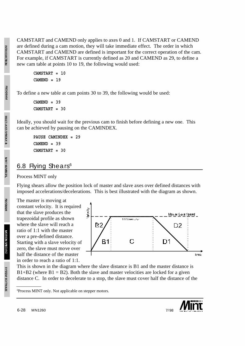
6-28 7/98
CAMSTART and CAMEND only applies to axes 0 and 1. If CAMSTART or CAMENDare defined during a cam motion, they will take immediate effect. The order in whichCAMSTART and CAMEND are defined is important for the correct operation of the cam.For example, if CAMSTART is currently defined as 20 and CAMEND as 29, to define anew cam table at points 10 to 19, the following would used:
CAMSTART = 10
CAMEND = 19
To define a new table at cam points 30 to 39, the following would be used:
CAMEND = 39
CAMSTART = 30
Ideally, you should wait for the previous cam to finish before defining a new one. Thiscan be achieved by pausing on the CAMINDEX.
PAUSE CAMINDEX = 29
CAMEND = 39
CAMSTART = 30
6.8 Flying Shears6
Process MINT only
Flying shears allow the position lock of master and slave axes over defined distances withimposed accelerations/decelerations. This is best illustrated with the diagram as shown.
The master is moving atconstant velocity. It is requiredthat the slave produces thetrapezoidal profile as shownwhere the slave will reach aratio of 1:1 with the masterover a pre-defined distance.Starting with a slave velocity ofzero, the slave must move overhalf the distance of the masterin order to reach a ratio of 1:1.This is shown in the diagram where the slave distance is B1 and the master distance isB1+B2 (where B1 = B2). Both the slave and master velocities are locked for a givendistance C. In order to decelerate to a stop, the slave must cover half the distance of the
MN1260
6Process MINT only. Not applicable on stepper motors.

6-297/98
master as shown. The slave distance is D1 and the master distance is D1 + D2 (where D1= D2). If the slave is required to stop for a given distance on the master (E), a slavedistance of 0 is requested.
Within MINT, the slave distance is given by the FLY keyword, and the master distance byMASTERINC. In order to fulfill the profile given in the diagram, the following MINTprogram would be used:
MASTERINC = B1+B2 : REM B1 = B2
FLY = B1 : GO : REM AccelerateMASTERINC = C
FLY = C : GO : REM Slew speed
MASTERINC = D1+D2 : REM D1 = D2
FLY = D1 : GO : REM DecelerateMASTERINC = E
FLY = 0 : GO : REM Wait for a master distance of E
Note that for the slave to accelerate from zero speed to a 1:1 ratio with themaster, it must cover half the master distance i.e. FLY = MASTERINC/2.
For the slave to decelerate from a 1:1 ratio with the master to zero velocity, itmust again cover half the distance of the master, i.e. FLY = MASTERINC/2
(note that FLY is not negative).
Before the flying shear can be executed, it must be linked to an external source by usingthe FOLLOWAXIS keyword. The FOLLOWAXIS keyword determines the source of themaster input channel. It accepts one of the following values:
Value Function
3,4,5 Follow channels 0, 1 or 3 of the 3 channel encoder interfaceboard
0,1,2 Follow axes 0,1 or 2. MASTERINC is scaled by the SCALEfactor on the specified axis.
-1 Follow the demand speed set by the SPEED keyword. Thiswould be the same as having a constant master frequencyinput. Note that the MASTERINC value is not scaled andmust be expressed in quadrature counts.
-2 Follow the PULSE input. Note that the MASTERINC valueis not scaled and must be expressed in quadrature counts.
MN1260
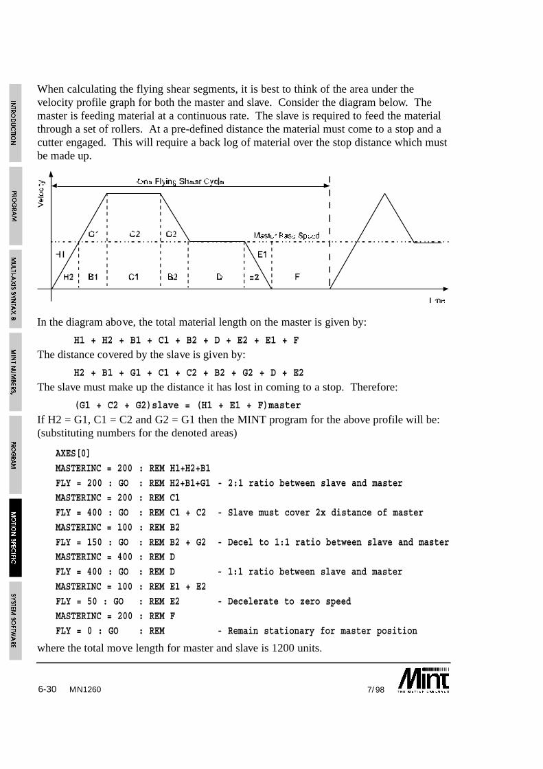
6-30 7/98
When calculating the flying shear segments, it is best to think of the area under thevelocity profile graph for both the master and slave. Consider the diagram below. Themaster is feeding material at a continuous rate. The slave is required to feed the materialthrough a set of rollers. At a pre-defined distance the material must come to a stop and acutter engaged. This will require a back log of material over the stop distance which mustbe made up.
In the diagram above, the total material length on the master is given by:
H1 + H2 + B1 + C1 + B2 + D + E2 + E1 + F
The distance covered by the slave is given by:
H2 + B1 + G1 + C1 + C2 + B2 + G2 + D + E2
The slave must make up the distance it has lost in coming to a stop. Therefore:
(G1 + C2 + G2)slave = (H1 + E1 + F)master
If H2 = G1, C1 = C2 and G2 = G1 then the MINT program for the above profile will be:(substituting numbers for the denoted areas)
AXES[0]
MASTERINC = 200 : REM H1+H2+B1
FLY = 200 : GO : REM H2+B1+G1 - 2:1 ratio between slave and masterMASTERINC = 200 : REM C1
FLY = 400 : GO : REM C1 + C2 - Slave must cover 2x distance of master
MASTERINC = 100 : REM B2
FLY = 150 : GO : REM B2 + G2 - Decel to 1:1 ratio between slave and masterMASTERINC = 400 : REM D
FLY = 400 : GO : REM D - 1:1 ratio between slave and master
MASTERINC = 100 : REM E1 + E2
FLY = 50 : GO : REM E2 - Decelerate to zero speedMASTERINC = 200 : REM F
FLY = 0 : GO : REM - Remain stationary for master position
where the total move length for master and slave is 1200 units.
MN1260

6-317/98
Notes on Flying Shears
• 10 milli-seconds should be allowed in order to set-up a flying shear segment, where aflying shear segment is defined as a FLY/MASTERINC combination.
• The master position must be uni-directional.
• The slave (fly) will move on the direction defined by the FLY keyword regardless ofthe direction of the master. In order to move the slave backwards, the negative FLYmust be given.
• From esMINT v2.71, an OFFSET move can be placed on a FLY (or multiple FLY)segments.
6.8.1 Example of a Flying ShearA common problem in industrial automation is to perform an operation on a continuouslymoving web, extrusion, or other material which is generated by a continuous productionprocess. Examples of this type of operation are cropping metal produced from a rollingmill, slitting plastic bags across their width or placing labels on a backing strip.
Each application has the common requirement that the operation must be performed at aregular distance on the moving web. The usual method of achieving this is to use a linearslide which moves forward in synchronism with the web during the operation and returnsquickly to datum before commencing the next operation.
At a programmable count the controller causes the servo motor to accelerate to web speedbefore turning on an output that causes the shear to operate. The servo motor thendecelerates to a stop and reverses to return the slide to the start position. The velocity ofthe linear slide with respect to the position of the web for one cycle is shown on thefigure. This profile is repeated for each operation on the web.
The FLY keyword in MINT is used to perform this velocity profile. The FLY functionallows the position of the slave axis to be specified with respect to the position of a masteraxis so that the two are locked together.
This is analogous to a mechanical cam and push rod assembly, the major advantage beingthat the software system is mechanically simpler and can be changed (i.e. different lengthsof cut) at the press of a button. The controller can also synchronize other machinefunctions in a similar way to a PLC and keep track of the total amount of material cut etc.,which can be displayed on an operator message panel.
The following MINT program specifies each movement segment in terms of the distanceto be moved on the linear slide for a given distance on the master encoder. The shear andproduct are therefore always in correct synchronism even if the speed of the product variesthroughout a cycle.
MN1260

6-32 7/98
Example:
A flying shear isrequired to cut productevery 52 units. Theshear can travel over adistance of 20 units,of which 13 units areused in this example.
Hint:
Define the flying shear such that the master travel, given the forward and reverse travel ofthe knife, is less than the minimum cut length. To change the cut length only the dwelltime between knife moves needs to be altered. Alternatively, the knife return profile canbe altered.
AXES[0]FOLLOWAXIS[0] = 1 : REM Follow axis 1GOSUB main#main
LOOPMASTERINC = 20FLY = 0 : REM Wait 20 units on the masterGOMASTERINC = 3 : REM Accelerate to 1:1 ratio over 3 units of masterFLY = 1.5GOMASTERINC = 10 : REM Follow at 1:1 over 10 units of masterFLY = 10GOOUT0 = 1 : REM Activate the shear (note buffered moves)MASTERINC = 3FLY = 1.5 : REM Decelerate to stop over 3 units of masterGOOUT0 = 0 : REM De-activate the shear (note buffered moves)MASTERINC = 8 : REM Return to startFLY = -6.5GOFLY = -6.5GO
ENDLRETURN
MN1260

6-337/98
Note the placement of the OUT0 statements. These appear to occur at the wrong flysegment, however, due to the nature of MINT with buffered moves, it is necessary to placethe OUT0 statement after the fly segment following the segment where you require thecommand to be performed. For example:
FLY = 10 : GO
OUT2 = 1 : REM Executed immediately, before FLY = 10 has completed ie: REM when FLY = 10 starts
FLY = 20 : GO
OUT1 = 1 : REM Executed when FLY = 20 has started, ie when FLY=10
: REM has finished
The total movement of the material is given by:
20 + 3 + 10 + 3 + 8 + 8 = 52
The first cut will however be short by 29 units, since the shear will cut at 20 + 3 units.
The shear moves 1.5 units to accelerate to a ratio of 1:1, moves 10 units with the materialand decelerates over 1.5 units, giving a total distance on the slave of 13 units.
Note that to ramp up to a ratio of 1:1, the ratio of MASTERINC to FLY is 2:1.
6.9 Triggered Moves
Process MINT only
The TRIGGER keyword allows a move to be defined but not executed until an input goeslow. TRIGGER uses the syntax as shown:
TRIGGER.axis = <input channel>
For example:
TRIGGER.2 = 1
MOVEA.2 = 100 : GO.2
When input 1 goes low, axis 2 will move to position 100. This replaces the followingcode:
#IN1
MOVEA.2 = 100 : GO.2RETURN
The advantage of using TRIGGER over an interrupt, is that the move is guaranteed to startwithin 1 servo cycle (2ms typically).
MN1260
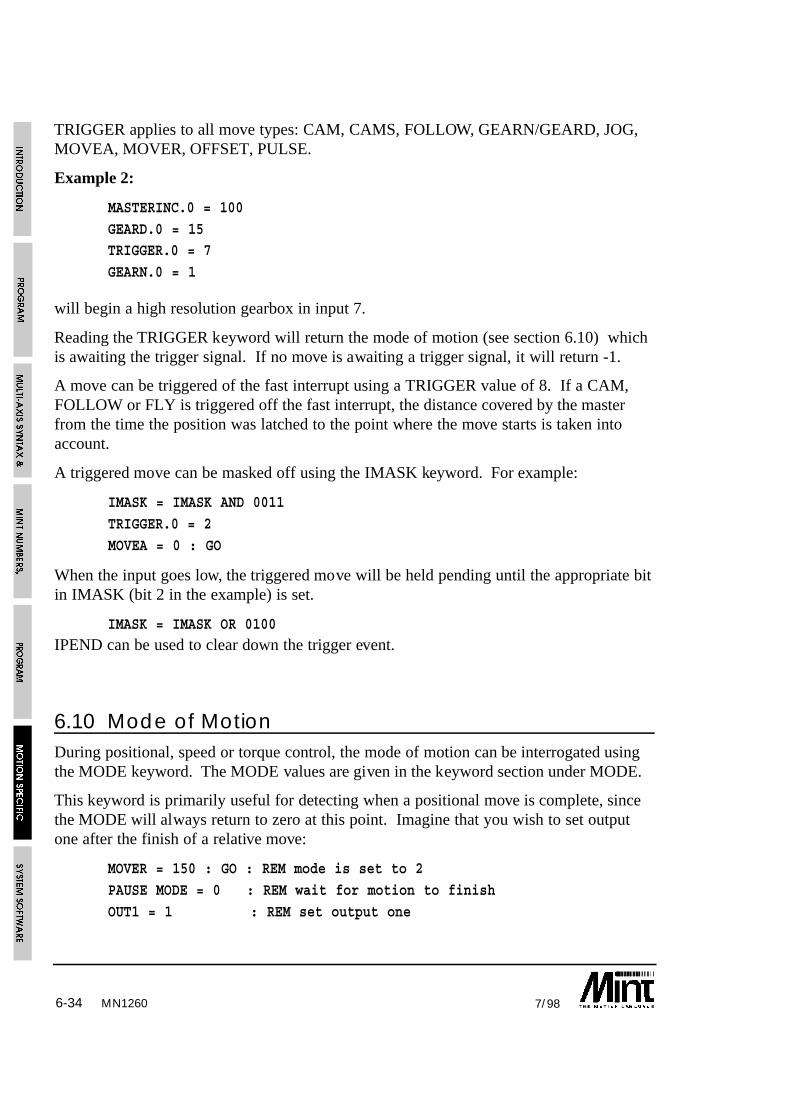
6-34 7/98
TRIGGER applies to all move types: CAM, CAMS, FOLLOW, GEARN/GEARD, JOG,MOVEA, MOVER, OFFSET, PULSE.
Example 2:
MASTERINC.0 = 100
GEARD.0 = 15TRIGGER.0 = 7
GEARN.0 = 1
will begin a high resolution gearbox in input 7.
Reading the TRIGGER keyword will return the mode of motion (see section 6.10) whichis awaiting the trigger signal. If no move is awaiting a trigger signal, it will return -1.
A move can be triggered of the fast interrupt using a TRIGGER value of 8. If a CAM,FOLLOW or FLY is triggered off the fast interrupt, the distance covered by the masterfrom the time the position was latched to the point where the move starts is taken intoaccount.
A triggered move can be masked off using the IMASK keyword. For example:
IMASK = IMASK AND 0011
TRIGGER.0 = 2
MOVEA = 0 : GO
When the input goes low, the triggered move will be held pending until the appropriate bitin IMASK (bit 2 in the example) is set.
IMASK = IMASK OR 0100IPEND can be used to clear down the trigger event.
6.10 Mode of MotionDuring positional, speed or torque control, the mode of motion can be interrogated usingthe MODE keyword. The MODE values are given in the keyword section under MODE.
This keyword is primarily useful for detecting when a positional move is complete, sincethe MODE will always return to zero at this point. Imagine that you wish to set outputone after the finish of a relative move:
MOVER = 150 : GO : REM mode is set to 2
PAUSE MODE = 0 : REM wait for motion to finish
OUT1 = 1 : REM set output one
MN1260

6-357/98
Alternatively:
PAUSE MODE = 0
can be replaced by:
PAUSE IDLE
Example 2:
PAUSE MODE.0 = 0 AND MODE.1 = 0
can be replaced by:
PAUSE IDLE[0,1]
Example 3:
PULSE = 1 : REM Pulse following mode at ratio of 1:1
LOOP
PAUSE IN1 : REM Wait for a falling edge on input 1
PAUSE !IN1REM Perform a positional offset on seeing the input
REM signal
OFFSET = offsetValue
REM Wait for offset to finishPAUSE MODE = _pulse
ENDL
this will follow an incoming pulse train and perform a positional offset on seeing digitalinput 1. The use of “PAUSE MODE = _pulse” will wait for the offset to finish execution.
The 7 segment status display also indicates the mode of motion. Section 8.3 covers this indetail.
6.11 Digital Input/Output
The controller has 8 general purpose digital inputs and 8 general purpose digital outputsthat are software controlled from MINT. The keywords IN and OUT are used to read andwrite to the I/O. Alternatively, interrupts can be set-up on the inputs using the #INxsubroutines (see section 5.3.2).
MN1260
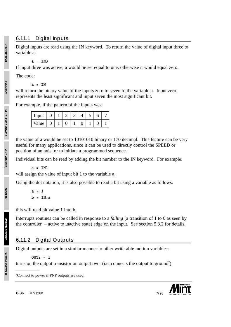
6-36 7/98MN1260
7Connect to power if PNP outputs are used.
6.11.1 Digital Inputs
Digital inputs are read using the IN keyword. To return the value of digital input three tovariable a:
a = IN3
If input three was active, a would be set equal to one, otherwise it would equal zero.
The code:
a = IN
will return the binary value of the inputs zero to seven to the variable a. Input zerorepresents the least significant and input seven the most significant bit.
For example, if the pattern of the inputs was:
Input 0 1 2 3 4 5 6 7
Value 0 1 0 1 0 1 0 1
the value of a would be set to 10101010 binary or 170 decimal. This feature can be veryuseful for many applications, since it can be used to directly control the SPEED orposition of an axis, or to initiate a programmed sequence.
Individual bits can be read by adding the bit number to the IN keyword. For example:
a = IN1
will assign the value of input bit 1 to the variable a.
Using the dot notation, it is also possible to read a bit using a variable as follows:
a = 1
b = IN.a
this will read bit value 1 into b.
Interrupts routines can be called in response to a falling (a transition of 1 to 0 as seen bythe controller – active to inactive state) edge on the input. See section 5.3.2 for details.
6.11.2 Digital Outputs
Digital outputs are set in a similar manner to other write-able motion variables:
OUT2 = 1
turns on the output transistor on output two (i.e. connects the output to ground7)
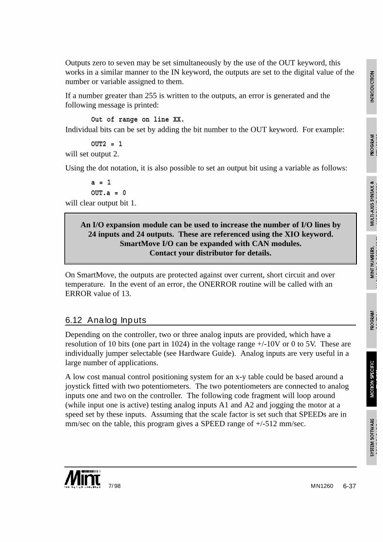
6-377/98
Outputs zero to seven may be set simultaneously by the use of the OUT keyword, thisworks in a similar manner to the IN keyword, the outputs are set to the digital value of thenumber or variable assigned to them.
If a number greater than 255 is written to the outputs, an error is generated and thefollowing message is printed:
Out of range on line XX.
Individual bits can be set by adding the bit number to the OUT keyword. For example:
OUT2 = 1will set output 2.
Using the dot notation, it is also possible to set an output bit using a variable as follows:
a = 1
OUT.a = 0
will clear output bit 1.
An I/O expansion module can be used to increase the number of I/O lines by24 inputs and 24 outputs. These are referenced using the XIO keyword.
SmartMove I/O can be expanded with CAN modules.Contact your distributor for details.
On SmartMove, the outputs are protected against over current, short circuit and overtemperature. In the event of an error, the ONERROR routine will be called with anERROR value of 13.
6.12 Analog Inputs
Depending on the controller, two or three analog inputs are provided, which have aresolution of 10 bits (one part in 1024) in the voltage range +/-10V or 0 to 5V. These areindividually jumper selectable (see Hardware Guide). Analog inputs are very useful in alarge number of applications.
A low cost manual control positioning system for an x-y table could be based around ajoystick fitted with two potentiometers. The two potentiometers are connected to analoginputs one and two on the controller. The following code fragment will loop around(while input one is active) testing analog inputs A1 and A2 and jogging the motor at aspeed set by these inputs. Assuming that the scale factor is set such that SPEEDs are inmm/sec on the table, this program gives a SPEED range of +/-512 mm/sec.
MN1260

6-38 7/98
WHILE IN1JOG = A1 - 512 : REM 0V input produces..
JOG = ,A2 - 512 : REM ..zero speed
ENDW
closing a switch connected to input one will cause the loop to terminate.
Section 4.5.2, on array data, shows an example program using the above to store a seriesof x-y positions in an array for later use.
The following section describes a use for analog inputs using a joystick.
6.12.1 Joystick Control in MINT/3.28
Stepper Controllers Only
Since MINT/3.28 is not a programming language, but is under host control, it is difficultto implement joystick control using the analog inputs. For this reason, commands are nowavailable in MINT/3.28 for joystick control. Parameters can be set for a deadband, theanalog midpoint etc. The following diagram best explains the operation of the joystickcontrol:
The regions of operation are:
• DEADBAND: Over this region there will be no movement.
• FIXED SPEED DEADBAND: Over this region, the motor will move at 1 pulse everysecond for fine position control.
• NORMAL: Normal operation where the velocity of the motor is related to the analoginput voltage. The maximum velocity is controlled by the SPEED keyword.
MN1260
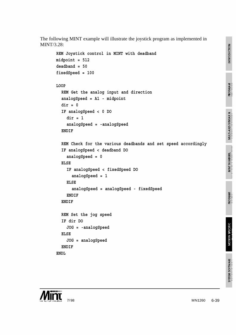
6-397/98
The following MINT example will illustrate the joystick program as implemented inMINT/3.28:
REM Joystick control in MINT with deadband
midpoint = 512deadband = 50
fixedSpeed = 100
LOOP
REM Get the analog input and directionanalogSpeed = A1 - midpoint
dir = 0
IF analogSpeed < 0 DO
dir = 1analogSpeed = -analogSpeed
ENDIF
REM Check for the various deadbands and set speed accordinglyIF analogSpeed < deadband DO
analogSpeed = 0
ELSE
IF analogSpeed < fixedSpeed DOanalogSpeed = 1
ELSE
analogSpeed = analogSpeed - fixedSpeed
ENDIFENDIF
REM Set the jog speed
IF dir DOJOG = -analogSpeed
ELSE
JOG = analogSpeed
ENDIF
ENDL
MN1260

6-40 7/98MN1260
The commands available in MINT/3.28 for joystick control are:
Name Type Range Default Description
JD Write 0 - 1023 0 Sets the deadband whereby there will be nomovement on the axis
JF Write 0 - 1023 0 Sets the fixed speed deadband
JM Write 0 - 1023 512 Sets the analog input midpoint for bi-directionalcontrol
JS Write 1 - 32767 1000 Factor used for mode 2 of joystick control
JY Write 1 - 2 - Enable joystick mode and set the mode ofoperation:1. Axis speed is related to analog input voltage2. Axis speed is related to the cube of the analog
input voltage to allow more variable speedcontrol
There are two modes of operation for joystick control, as controlled by the JY keyword.
Mode1:
The axis speed is related to the following expression:
JOG = analogSpeed - fixedSpeed
using the MINT program above as a reference where fixedSpeed would be set by JF.
Mode 2:
The axis speed to related to the cube of the analog input:
JOG = (analogSpeed - fixedSpeed)3 / JS
as the joystick is moved, the speed will increase more rapidly than with the linear ramp ofmode 1.
Notes:
• The speed for both modes 1 and 2 are dependent on the scale factor (SF).
• The top speed is restricted by the speed keyword (SP)
• Normal operation is resumed after a stop command (ST)

6-417/98
Using cTERM for DOS, the following file can be sent to the controller using theMINT/3.28 ‘Load File’ option.
C;0;RE;6
C;0;DL;6W;0;SP;3;5000,5000
W;0;JD;3;50,50
W;0;JF;3;100,100
W;0;JM;3;512,512
W;0;JS;3;3000,3000W;0;JY;3;2,2
The above parameters will set a deadband (JD) of 50 bits from a midpoint of 512. Thefixed speed deadband (JF) will be between 50 and 100 bits from the midpoint. Mode 2joystick operation is used.
6.13 Input/Output ‘On the Fly’MINT can test and respond to inputs during execution of positional moves because it willcontinue to run until it detects that a move instruction will interfere with one that isalready executing. Consider the following code fragment:
MOVEA = 100 : REM move first axis
GO.0MOVEA = ,200 : REM move second axis
GO.1
MOVEA = 200 : REM set-up next move
GO.0 : REM program hangs here
MINT will start the positional move on axis 0, then start the positional move on axis 1. Itwill then set-up the next positional move on axis 0 as the move pending, but when itcomes to execute GO[0], the program will stop execution until the move on axis 0 iscomplete. Similarly, if a statement GO[0,1] was encountered and a move was in progresson either axis 0 or axis 1, the program would stop execution until that move was complete.
Because MINT does not stop executing instructions until there is a move pending it iseasy to write applications that perform AND operations while a move is in progress.
An example is glue laying around car windows. In this application, the glue cannot beturned on until the axis has reached a critical velocity (VEL), otherwise the line of gluewill not be consistently thick. Therefore we must wait until the axis has acceleratedbefore turning on the glue gun:
MN1260

6-42 7/98
MOVEA = 200 : GO : REM start move PAUSE VEL > 20 : REM wait until VEL > 20
OUT1 = 1 : REM turn on glue
PAUSE VEL < 20 : REM decelerating to end
OUT1 = 0 : REM turn off glue
There are instances when you may wish to halt the program until the current move iscomplete. For instance:
OUT2 = 0
MOVER = 10 : GO : REM relative movePAUSE IDLE : REM wait for end move
OUT2 = 1 : REM flag end move
In this code fragment the requirement is that output two is not set until the move iscomplete. The IDLE keyword will return zero during a positional move and one whenthe axis is idle at the end of the move. Therefore PAUSEing on IDLE will hang theprogram as required.
For a 2 axis move, the code segment will be:
OUT2 = 0MOVER = 10,20 : GO : REM relative move
PAUSE IDLE[0,1] : REM wait for end move
OUT2 = 1 : REM flag end move
Using interrupts, it is possible to interrupt program execution to perform anotheroperation. See section 5.3.2.
6.14 The STOP InputThe STOP input is used to halt motion on all axes. When stop is asserted, motion willramp down to a stop at a deceleration rate set by the ACCEL keyword or crash stop in thecase of FOLLOW and cam profiling. If the input is negated (closed circuit) motion willcommence again and the program will continue to run as normal. An S is displayed onthe status display to indicate that motion has been interrupted.
Typically, the STOP input should be wired to the safety guard on the installation, this willensure that motion is prevented when the guard is lifted. This is a safety requirement.Where the application permits, it is recommended that an external circuit breaker isinstalled to physically cut power to the motor for maximum operator safety.
MN1260
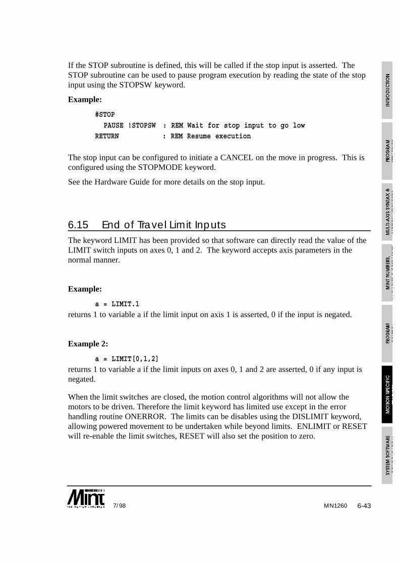
6-437/98
If the STOP subroutine is defined, this will be called if the stop input is asserted. TheSTOP subroutine can be used to pause program execution by reading the state of the stopinput using the STOPSW keyword.
Example:
#STOP
PAUSE !STOPSW : REM Wait for stop input to go lowRETURN : REM Resume execution
The stop input can be configured to initiate a CANCEL on the move in progress. This isconfigured using the STOPMODE keyword.
See the Hardware Guide for more details on the stop input.
6.15 End of Travel Limit InputsThe keyword LIMIT has been provided so that software can directly read the value of theLIMIT switch inputs on axes 0, 1 and 2. The keyword accepts axis parameters in thenormal manner.
Example:
a = LIMIT.1
returns 1 to variable a if the limit input on axis 1 is asserted, 0 if the input is negated.
Example 2:
a = LIMIT[0,1,2]
returns 1 to variable a if the limit inputs on axes 0, 1 and 2 are asserted, 0 if any input isnegated.
When the limit switches are closed, the motion control algorithms will not allow themotors to be driven. Therefore the limit keyword has limited use except in the errorhandling routine ONERROR. The limits can be disables using the DISLIMIT keyword,allowing powered movement to be undertaken while beyond limits. ENLIMIT or RESETwill re-enable the limit switches, RESET will also set the position to zero.
MN1260

6-44 7/98
Example:
#ONERROR
IF ERROR.1 = _limit DO : REM Limit on axis 1?DISLIMIT.1
SERVOFF.1
PAUSE !LIMIT.1
SERVOC.1
ENLIMIT.1ENDIF
RETURN
this example will, on detecting a limit error, disable the limits, and allow manualmovement off the limits. Power is restored and the limits are enabled.
In many applications it is necessary to have separate limit and home switches. Since thecontroller has only one limit input per axis it is best to arrange the active areas of theswitches as shown below:
Hitting a limit switch causes an error which is handled in software by the ONERRORsubroutine. By reading both the state of the limit and home inputs, the left or right limitswitch can be determined as shown in the table:
HOME LIMIT Action
on on Left limit hit
off on Right limit hit
If the home position is midway between the two limits, the active area of the home shouldbe made to extend to either the right or the left to the limit active area.
In an application where not all 3 axes are used, the redundant axes must have theirrespective limit switches grounded (connect to power if PNP inputs are used) for normaloperation. Alternatively the MINT keyword DISLIMIT can be used to disable thedetection of limit switches.
MN1260

7-17/98 MN1260
7. System Software Configuration
Depending upon the controller, each axis can be configured for its particular motor type.Motor types supported are::
• Servo motors with standard +/- 10V output
• Inverters with 0-10V and direction output
• Stepper motors including micro steppers
The stepper controller only supports stepper motors with no encoder feedback:
Each axis is configured using the CONFIG keyword. The values accepted by CONFIGare:
Value Constant Motor Type
0 _off Turn the axis off
1 _servo Servo motor
2 _stepper Stepper motor
3 _micro Micro stepper
4 _inverter Inverter 0-10v plus direction
Example:
CONFIG = _servo,_servo,_stepper
this will configure a servo controller for servo motors on the first two axes and a stepperon the third axes.
Example 2:
CONFIG = _micro;
this configures all 3 axes as micro steppers.
There is no difference between config mode 2 and 3 except the speed and accelerationdefaults are greater than for normal steppers.
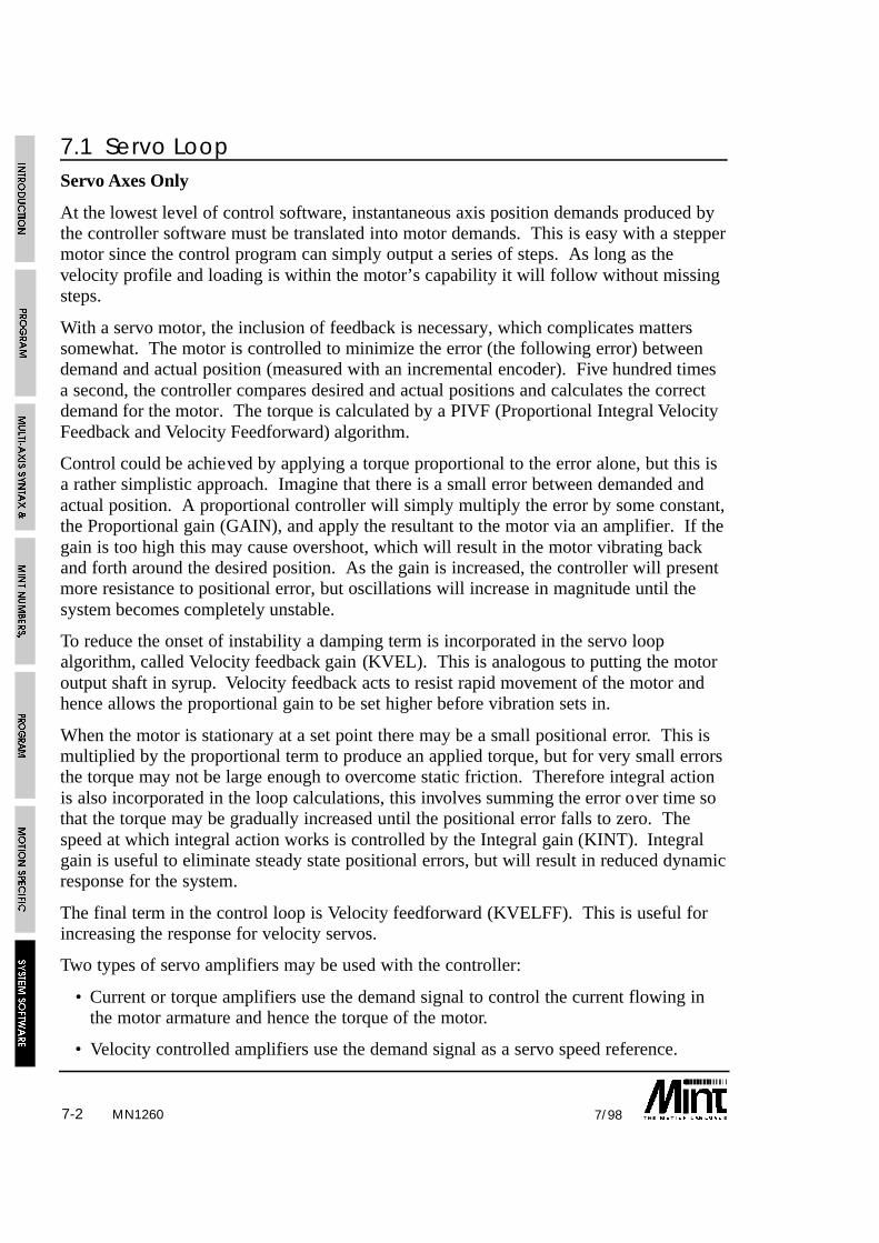
7-2 7/98
7.1 Servo LoopServo Axes Only
At the lowest level of control software, instantaneous axis position demands produced bythe controller software must be translated into motor demands. This is easy with a steppermotor since the control program can simply output a series of steps. As long as thevelocity profile and loading is within the motor’s capability it will follow without missingsteps.
With a servo motor, the inclusion of feedback is necessary, which complicates matterssomewhat. The motor is controlled to minimize the error (the following error) betweendemand and actual position (measured with an incremental encoder). Five hundred timesa second, the controller compares desired and actual positions and calculates the correctdemand for the motor. The torque is calculated by a PIVF (Proportional Integral VelocityFeedback and Velocity Feedforward) algorithm.
Control could be achieved by applying a torque proportional to the error alone, but this isa rather simplistic approach. Imagine that there is a small error between demanded andactual position. A proportional controller will simply multiply the error by some constant,the Proportional gain (GAIN), and apply the resultant to the motor via an amplifier. If thegain is too high this may cause overshoot, which will result in the motor vibrating backand forth around the desired position. As the gain is increased, the controller will presentmore resistance to positional error, but oscillations will increase in magnitude until thesystem becomes completely unstable.
To reduce the onset of instability a damping term is incorporated in the servo loopalgorithm, called Velocity feedback gain (KVEL). This is analogous to putting the motoroutput shaft in syrup. Velocity feedback acts to resist rapid movement of the motor andhence allows the proportional gain to be set higher before vibration sets in.
When the motor is stationary at a set point there may be a small positional error. This ismultiplied by the proportional term to produce an applied torque, but for very small errorsthe torque may not be large enough to overcome static friction. Therefore integral actionis also incorporated in the loop calculations, this involves summing the error over time sothat the torque may be gradually increased until the positional error falls to zero. Thespeed at which integral action works is controlled by the Integral gain (KINT). Integralgain is useful to eliminate steady state positional errors, but will result in reduced dynamicresponse for the system.
The final term in the control loop is Velocity feedforward (KVELFF). This is useful forincreasing the response for velocity servos.
Two types of servo amplifiers may be used with the controller:
• Current or torque amplifiers use the demand signal to control the current flowing inthe motor armature and hence the torque of the motor.
• Velocity controlled amplifiers use the demand signal as a servo speed reference.
MN1260

7-37/98
For general purpose applications, the torque amplifier is cheaper and simpler to set up, butthe velocity servo gives better control, especially in high performance applications. Fortorque amplifiers, velocity feedback must be used to stabilize the system, but this is notnormally required for a velocity servo since it incorporates its own internal velocityfeedback.
A block diagram of the complete control system, showing controller, amplifier, motor andgearbox is presented below. The servo amplifier may be a simple current amplifier, orincorporate internal velocity feedback via a tachometer.
This is a four term controller incorporating proportional, velocity feedback, velocityfeedforward and integral gains.
The equation of the loop closure algorithm is as follows:
Demand = GN.e - KV.v + KF.V + KI.∑e
e - following error (quad counts)
v - actual axis velocity (quad counts/sample time)
V - demand axis velocity (quad counts/sample time)
where the terms relate to the following MINT keywords:
Keyword Abbreviation Description
GAIN GN Proportional servo loop gain
KVEL KV Velocity feedback gain
KVELFF KF Velocity feedforward gain
KINT KI Integral feedback
MN1260

7-4 7/98
Tuning the drive involves changing the four servo loop gains, GN, KI, KV and KF toprovide the best performance for your particular motor/encoder combination and loadinertia. In view of the diversity of application, these values all default to zero and shouldbe set up in the system configuration file. You are advised to read the Getting StartedGuide for details on setting these parameters.
Two other keywords, KINTRANGE and CURRLIMIT, are used to control the DACoutput. KINTRANGE, the integration limit, determines the maximum value of the effectof integral action, KI.Se. KINTRANGE is specified as a percentage (%) of the full scaledemand output in the range of ±10V. Therefore if KINTRANGE = 25, the maximumeffect of integral action is ±2.5V.
CURRLIMIT, the current limit, so called for its use with current amplifiers, determinesthe maximum value of the demand output as a percentage of the full scale demand.Therefore if CURRLIMIT = 50, the maximum demand output will be ±5V.
The encoder gain (measured in pulses/rev) is one factor that is hardware dependent but hasa direct effect on the overall loop gain. The other four parameters are software controlledin the range of 0.0-255.0, the resolution of the decimal part is one part in 256 as withnormal MINT variables.
MN1260

7-57/98 MN1260
7.2 Inverter ControlMany inverters have a uni-directional input instead of a bi-directional input. MINTsupports inverters with a uni-directional input by giving a 0-10V reference voltage and adirection output. The actual direction output pin will depend upon the system used whichcan be found from the following lookup table:
System Axis Output pin Output Type
EuroSystem 0 Stepper direction 0 NPN open collector
(including STE) 1 Stepper direction 1 NPN open collector
2 Stepper direction 2 NPN open collector
SmartSystem/1 0 direction axis 0 NPN open collector
SmartSystem/2 0 direction axis 0 NPN open collector
1 direction axis 1 NPN open collector
0 Output bit 7 PNP open collector
EuroServo/3 1 Output bit 6 PNP open collector
2 Output bit 5 PNP open collector
0 Output bit 7 PNP open collector
SmartSystem/3 1 Output bit 6 PNP open collector
2 Output bit 5 PNP open collector
0 Output bit 7 PNP open collector
SmartMove 1 Output bit 6 PNP open collector
2 Output bit 5 PNP open collector
To enable inverter control, write 4 (_inverter) to the CONFIG keyword. For example:
CONFIG = _inverter
Note that for EuroServo/3 and SmartSystem/3, one of the user digital outputs will becomea direction output and cannot be used as a general purpose output.
Since it is not possible to swap the motor demand cables over, as with a bi-directionalsystem, the active output state of the inverter direction can be changed by writing to theDIR keyword.
DIR = 0
the output will be low for a requested negative motor direction (e.g. TQ = -10)
DIR = 1
the output will be high for a requested negative motor direction (e.g. TQ = -10)

7-6 7/98
7.3 Positional Resolution and User UnitsPositions can be specified to a resolution of ±8,388,608 encoder quadrature counts.Following error is the instantaneous difference between encoder position and the demandposition from the controller and can be read using the FOLERR keyword. The maximumpermissible following error is controllable via the MFOLERR parameter. This parameterdefaults to a value of 16,000 counts on power up. If the following error is greater than themaximum following error specified, the system will shut down and report an errorcondition. This is represented by an ‘F’ on the LED status display. MFOLERR is used asa safety feature. Should an axis hit an end stop, the motor will shut down when thefollowing error (FOLERR) exceeds the maximum following error (MFOLERR).
The SCALE keyword is used to allow you to set up the system so that you can implementthe motion control program in units that are meaningful to the application. In a simpleapplication, the requirement may be that positions are specified in revs, SPEED’s inrev/second and accelerations in revs/second. For a 500 line encoder, SCALE should be setto 2000 to achieve this. The factor of four is because the controller counts each edge ofthe two channel Encoder signal, these are called quadrature counts. Hence, the controllercounts 2000 pulses per rev for a 500 line encoder, 4000 for a 1000 line encoder etc.
On power up SCALE defaults to 1, so that all references are made in terms of quadraturecounts. The controller automatically converts all references to positions etc. to quadraturecounts in the low level routines that control the motor. Therefore use of the SCALEkeyword will proportionally reduce the numerical valid range for positions speeds etc.,without affecting the absolute resolution of the system. This is shown in the followingdiagram:
Note that SCALE will only accept integer values.Non-integer values will be rounded down.
Example of the use of SCALE:
An XY table uses servo motors with 500 line encoders and a 4 mil pitch. With quadratureencoders this gives 2000 counts per revolution of the motor or 500 counts per millimeter.
MN1260

7-77/98
To scale the positions and speeds to millimeters, the following could be used:
SCALE = 500,500 : REM Scale to mm
SPEED = 30,30 : REM Speed = 30 mm/secACCEL = 500,500 : REM Accel = 500 mm/sec^2
MFOLERR = 10,10 : REM Max following error of 10mm
MOVEA = 100,200 : GO : REM Move to position 100,200mm
MOVER = -10,-10 : GO : REM Move relative -10,-10mm
7.4 The Configuration FileThe configuration file is used to store all the defaults appropriate to the particular system.Whenever the program is RUN, the configuration file is first executed. A list ofparameters that you may wish to set up follows:
• Motor type, i.e. stepper or servo.
• Servo loop gains - to tune the system response. See the Getting Started Guide
• Scale factor - to set the units of measure of the application.
• Maximum following error (MFOLERR) - to set a safe maximum difference betweenactual and desired positions.
• Default speeds (SPEED) and accelerations (ACCEL) for the system - to determine theshape of the trapezoidal velocity profile (RAMP).
These parameters are generally set up only once for an application, but can at any time bealtered in the Program File.
MN1260
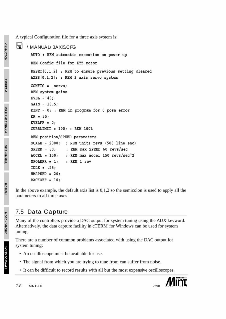
7-8 7/98
A typical Configuration file for a three axis system is:
! \MANUAL\3AXIS.CFG
AUTO : REM automatic execution on power up
REM Config file for XYZ motor
RESET[0,1,2] : REM to ensure previous setting cleared
AXES[0,1,2]: : REM 3 axis servo system
CONFIG = _servo;
REM system gains
KVEL = 40;GAIN = 10.5;
KINT = 0; : REM in program for 0 posn error
KR = 25;
KVELFF = 0;CURRLIMIT = 100; : REM 100%
REM position/SPEED parameters
SCALE = 2000; : REM units revs (500 line enc)
SPEED = 60; : REM max SPEED 60 revs/sec
ACCEL = 150; : REM max accel 150 revs/sec^2MFOLERR = 1; : REM 1 rev
IDLE = .25;
HMSPEED = 20;
BACKOFF = 10;
In the above example, the default axis list is 0,1,2 so the semicolon is used to apply all theparameters to all three axes.
7.5 Data CaptureMany of the controllers provide a DAC output for system tuning using the AUX keyword.Alternatively, the data capture facility in cTERM for Windows can be used for systemtuning.
There are a number of common problems associated with using the DAC output forsystem tuning:
• An oscilloscope must be available for use.
• The signal from which you are trying to tune from can suffer from noise.
• It can be difficult to record results with all but the most expensive oscilloscopes.
MN1260

7-97/98
The new data capture routines do away with these problems by capturing the data tomemory for later analysis. Data, such as axis velocity, axis following error, or position isstored as MINT array data. This can be easily uploaded to application programs such asMicrosoft Excel or cTERM for Windows for analysis.
Two keywords are associated with data capture:
CAPTURE Determines which axis and what data is captured. DATATIME Determines the time over which data is captured.
The following graph, produced in Excel, demonstrates the use of data capture:
DIM data(4000) : REM Reverse data points
DATATIME = 4000 : REM Capture 4 seconds of data
CAPTURE = 1 : REM Capture axis velocity
MR = 400 : GO : REM Perform a simple move
MR = -400 : GO
PAUSE IDLE : REM Wait for axis to become idle
FOR data = 1 TO 750 : REM Upload the data as a CSV file for
? data(data) : REM importing into Excel
NEXT
MN1260

7-10 7/98MN1260
Using data capture, one data source and one axis at a time can be captured. TheCAPTURE keyword defines the data source and the destination of the captured data asgiven in the table:
Value Description
1 Capture the axis velocity
2 Capture the axis following error
3 Capture the axis position
The axis, on which data you wish to capture, is specified by the axis when callingCAPTURE. For example:
CAPTURE.2 = 3
will capture the axis position on axis 2. Note that only the data on one axis can becaptured at any one time.
Data capture does not take into account any other arrays already defined on the controller.Data is captured and stored to the top of memory down until the DATATIME expires. Ifother array data is defined, or a large program is residing on memory, this can be over-written by the data capture values.
DIM xpos(10)DIM ypos(10)
DIM data(1000)
The data capture will over-write the values stored in xpos, ypos and data. Usually thisdoes not matter, since the data capture is used for tuning and not to analyze motorperformance in the final application.

MN1260 8-17/98
8. Program and Motion ErrorsErrors can be broken down into the following groups:
1. System errors
System errors include:
• Motion in Progress
• Out of Range
• Invalid Mode
• Servo Off
2. Motion errors
Motion errors include:
• Limit error
• Following error exceeded.
• External error
3. Programming errors
Run-time language errors such as Syntax Error.
MINT is able to handle a number of error conditions through the use of the keywordsERROR, ERRAXIS and ERR. When an error occurs, the error handler is called. This isdefined by placing a subroutine, #ONERROR, within the program. Only System Errorsand Motion Errors can be trapped within an ONERROR routine.
The ERR keyword is used to determine the nature of the error and ERRAXIS the axis onwhich the error occurred. ERR codes are as follows:

MN12608-2 7/98
System Error: These errors areassociated with the motion keywords
Out of range 0
reserved 1
reserved 2
Invalid axis setup 3
Invalid axis 4
Motion in progress 5
Servo off 6
reserved 7
Keyword not defined 8
reserved 9
Motion errors: These are async errorsthat result in motion shutdown. Theerror can be further investigated usingthe ERROR keyword.
reserved 10
Following Error 11
Limit Error 12
Card Aborted 13
External Error 14
Digital Output Fault 15
Using ERR codes, an ONERROR may look like the following:
#ONERROR
REM System Error. Re-run the systemIF ERR < 10 DO
PRINT “System Error”
PAUSE INKEY = ‘ ‘
RUNENDIF

MN1260 8-37/98
REM Motion error. Determine the nature of the error by readingREM the ERROR keyword.
IF ERR > 10 DO
IF ERROR.0 = _limit OR ERROR.1 = _limit DO
DISLIMIT[0,1]SERVOFF[0,1]
PAUSE !LIMIT.0 AND !LIMIT.1
SERVOC[0,1]
ENLIMIT[0,1]ENDIF
ENDIF
Note that once set, ERR is not cleared down and retains a value equivalent tothe last reported error.
8.1 Program ErrorsProgramming errors are usually silly mistakes like forgetting to put a bracket at the end ofan expression, or forgetting a NEXT at the end of a FOR loop. Programming errors resultin the program terminating with an error message and the LED status display showing an‘E’. If no terminal was connected to the system when the error occurred, the error can beread by typing LASTERR at the command line. For example:
LASTERR
might return:
ERROR: Program: Syntax error at line 123
or:
ERROR: Program: Out of range at line 10 on axis 2
Using either the onboard line editor or an off-line editor, the error should be corrected andthe program re-executed using the RUN command. A list of all error messages is given insection 11.
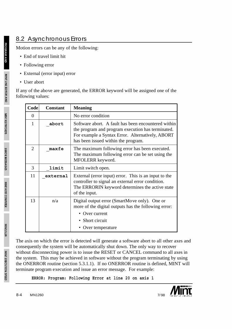
MN12608-4 7/98
8.2 Asynchronous ErrorsMotion errors can be any of the following:
• End of travel limit hit
• Following error
• External (error input) error
• User abort
If any of the above are generated, the ERROR keyword will be assigned one of thefollowing values:
Code Constant Meaning
0 No error condition
1 _abort Software abort. A fault has been encountered withinthe program and program execution has terminated.For example a Syntax Error. Alternatively, ABORThas been issued within the program.
2 _maxfe The maximum following error has been executed.The maximum following error can be set using theMFOLERR keyword.
3 _limit Limit switch open.
11 _external External (error input) error. This is an input to thecontroller to signal an external error condition.The ERRORIN keyword determines the active stateof the input.
13 n/a Digital output error (SmartMove only). One ormore of the digital outputs has the following error:
• Over current
• Short circuit
• Over temperature
The axis on which the error is detected will generate a software abort to all other axes andconsequently the system will be automatically shut down. The only way to recoverwithout disconnecting power is to issue the RESET or CANCEL command to all axes inthe system. This may be achieved in software without the program terminating by usingthe ONERROR routine (section 5.3.1.1). If no ONERROR routine is defined, MINT willterminate program execution and issue an error message. For example:
ERROR: Program: Following Error at line 20 on axis 1

MN1260 8-57/98
The external error is triggered through an input on the controller. The state of this inputcan be software configured using the ERRORIN keyword which accepts the followingvalues:
Value Function
0 Error input active low.
1 Error input active high
2 Error input disabled
ERRORIN by default is 2 and must therefore be configured to either 0 or 1 if used.
8.2.1 Error Handling using ONERROR
Whenever there is a motion error, MINT cannot continue to process motion commands.Normally this causes the interpreter to abort execution and return to command lineprompt.
In many applications, the controller must be able to recover from an error without theoperator powering up the system again. This facility is provided by the ONERROR key-word. When a motion error occurs, MINT looks for a subroutine called #ONERROR(note the use of the # as in a normal subroutine). If such a subroutine exists, MINTexecutes it.
ONERROR subroutine may be used to perform a number of actions:
• Test the error keyword to identify the type of error that occurred.
• RESET the controller and re-datum the equipment, then re-run the program from startusing RUN.
• CANCEL the current move and resume program execution from the point at whichthe error occurred using RETURN.
• Terminate program execution using END.
• Disable the limits, using DISLIMIT, allowing powered movement while beyond thelimit switches.

MN12608-6 7/98
Example:
#ONERROR
REM Output error on SmartMoveIF ERR = 15 DO
PRINT “Outputs in error. Check circuit and reset”
PAUSE 0
ENDIF
REM Check for motion errors
IF ERR >= 10 AND ERR < 15 DO
REM max following error exceeded, cancel current move then resume ..
REM ..program from where it stoppedIF ERROR.0 = _maxfe THEN CANCEL : RETURN
REM limit switch closed, call operator, wait for the operator to ..
REM .. manually move off the limit switch, RESET controller then ..REM .. re-run program from start
IF ERROR.0 = _limit DO
PRINT “Limit error - please re-position table”
REM wait for limit switches on axes 0 and 1 to open PAUSE LIMIT.0 = 0 & LIMIT.1 = 0 : REM Could use LIMIT[0,1]
RESET
RUN
ENDIFENDIF
REM Misc error
PRINT “Error “, ERR, “reported”
PAUSE 0END
The difference between RESET and CANCEL is that RESET will set the axis position tozero as well as clearing the error. CANCEL simply clears the error condition and thecurrent motion in progress, but does not set the axis positions to zero. This allows theONERROR routine to recover from the error without losing the current position.
The keyword DISLIMIT may be used to disable limit switches after the machine has hitthe end-stops so that the operator can drive the machine back into a safe operating zone.DISLIMIT will automatically issue a CANCEL command to clear the error. Limitswitches can be re-enabled by the keyword ENLIMIT.

MN1260 8-77/98
The motion error must be cleared before a motion variable can be written to.Failure to do so will result in program termination.
8.3 Front Panel Status DisplayThe status display is a single character display indicating axis status and error conditions.During normal operation it will display the current move in progress on axis 0 ,1 or 2,depending on the keyword LED.
LED = 0
sets the LED display to show the current status of axis 0. Similarly:
LED = 1
sets the display for axis 1. The bottom left dot on the LED is illuminated when axis 1status is displayed.
If an error occurs, the status of all axes will be displayed at approximately one secondintervals.
8.3.1 Error Conditions
Display Meaning
Ø External (error input) error. This is an input to the controllerto signal an external error condition. The ERRORIN keyworddetermines the active state of the input.
E Software abort. A fault has been encountered within theprogram and program execution has terminated. For examplea Syntax Error. Alternatively, ABORT has been issued withinthe program.
F The maximum following error has been executed. Themaximum following error can be set using the MFOLERRkeyword.
L Limit switch open
ß Digital output error (SmartMove only). One or more of thedigital outputs has the following error:
• Over current
• Short circuit
• Over temperature
The actual error condition can be read using the ERROR keyword.
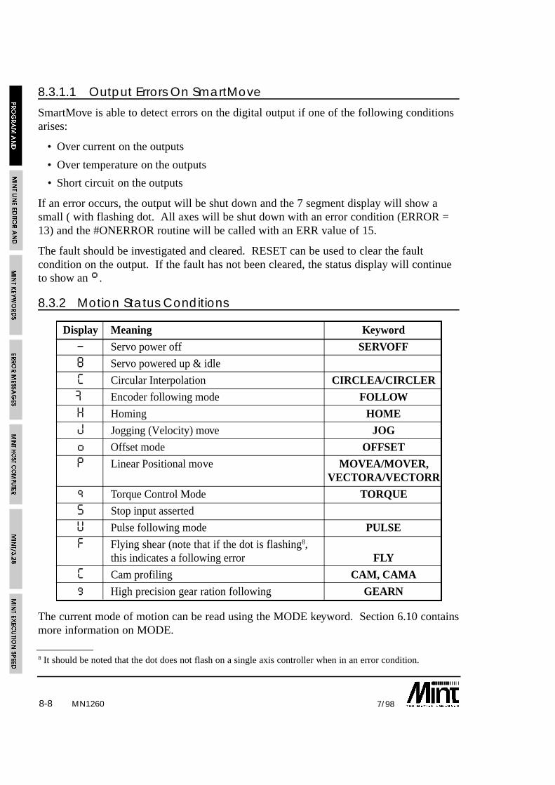
MN12608-8 7/98
8 It should be noted that the dot does not flash on a single axis controller when in an error condition.
8.3.1.1 Output Errors On SmartMove
SmartMove is able to detect errors on the digital output if one of the following conditionsarises:
• Over current on the outputs
• Over temperature on the outputs
• Short circuit on the outputs
If an error occurs, the output will be shut down and the 7 segment display will show asmall ( with flashing dot. All axes will be shut down with an error condition (ERROR =13) and the #ONERROR routine will be called with an ERR value of 15.
The fault should be investigated and cleared. RESET can be used to clear the faultcondition on the output. If the fault has not been cleared, the status display will continueto show an ß.
8.3.2 Motion Status Conditions
Display Meaning Keyword
– Servo power off SERVOFF
8 Servo powered up & idle
C Circular Interpolation CIRCLEA/CIRCLER
Æ Encoder following mode FOLLOW
H Homing HOME
J Jogging (Velocity) move JOG
o Offset mode OFFSET
P Linear Positional move MOVEA/MOVER,VECTORA/VECTORR
q Torque Control Mode TORQUE
S Stop input asserted
U Pulse following mode PULSE
F Flying shear (note that if the dot is flashing8,this indicates a following error FLY
C Cam profiling CAM, CAMA
g High precision gear ration following GEARN
The current mode of motion can be read using the MODE keyword. Section 6.10 containsmore information on MODE.

MN1260 9-17/98
9. MINT Line Editor and Program BuffersAn application program consists of 2 files, the configuration file used for storing programdefaults and set-up parameters, and the program file for storing the application program.The configuration file would usually be set once for a particular system, whereas theprogram file may change regularly in some applications (for instance: component insertionin printed circuit boards). To switch between the two files for editing, the CON andPROG keywords are used.
28,000 characters (bytes) of RAM space is availablefor program storage. The size of the configurationfile is fixed at 1000 bytes but the program size islimited only by available memory. The controllermemory is split as shown.
Note the area of memory labeled compiled code.MINT programs are not interpreted in the true senseof the word but are compiled into an intermediatecode for faster execution. When a program is firstexecuted either by the RUN command or the AUTOcommand, the source code iirst compiled thenexecuted. Depending upon the length of theapplication, this can take a couple of seconds. Thecompiled code is placed at the end of the programcode and in most cases is about 50% the size of theprogram code. The FREE keyword can be used todetermine the amount of available free memory. Ifmemory is a problem, the program code can besquashed using the SQUASH facility in cTERM forWindows.
Program and configuration files can be created using the on-board line editor oralternatively can be created off-line using a PC editor (cTERM) and then downloading thesource code. The maximum line length must be restricted to 75 characters when using theonboard editor. A restriction of 127 characters per line apply when using an offline editor.
Using the on-board editor, the editor commands are available from the user ‘P>’ or ‘C>’prompt. A summary of the commands are:
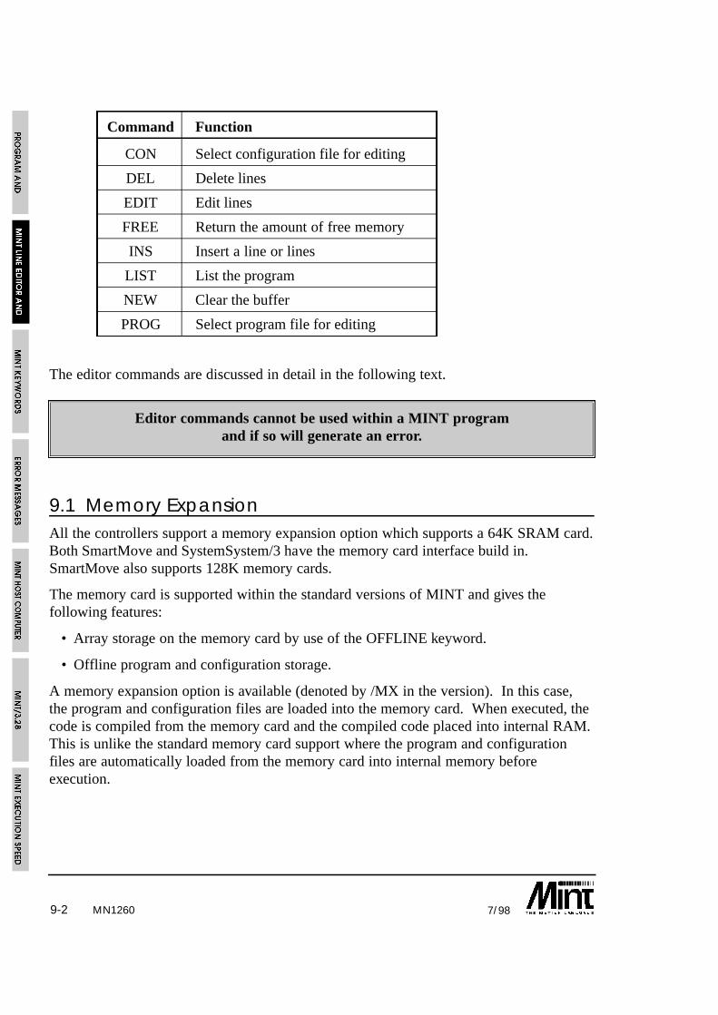
MN12609-2 7/98
Command Function
CON Select configuration file for editing
DEL Delete lines
EDIT Edit lines
FREE Return the amount of free memory
INS Insert a line or lines
LIST List the program
NEW Clear the buffer
PROG Select program file for editing
The editor commands are discussed in detail in the following text.
Editor commands cannot be used within a MINT programand if so will generate an error.
9.1 Memory ExpansionAll the controllers support a memory expansion option which supports a 64K SRAM card.Both SmartMove and SystemSystem/3 have the memory card interface build in.SmartMove also supports 128K memory cards.
The memory card is supported within the standard versions of MINT and gives thefollowing features:
• Array storage on the memory card by use of the OFFLINE keyword.
• Offline program and configuration storage.
A memory expansion option is available (denoted by /MX in the version). In this case,the program and configuration files are loaded into the memory card. When executed, thecode is compiled from the memory card and the compiled code placed into internal RAM.This is unlike the standard memory card support where the program and configurationfiles are automatically loaded from the memory card into internal memory beforeexecution.

MN1260 9-37/98
The following table compares the features of the memory expansion against standardmemory card support:
Feature Standard /M Expanded /MX
Max number of variables 50 100
Max number of sub-routines 40 80
Max program size (This depends upon 16K approx 60K approxthe available space for the compiled code). (64K RAM card)
OFFLINE array data 3 3
Support for onboard MINT line editor 3 7
See section 4.5.1 for further details on the memory card functionality.

MN12609-4 7/98
9.2 Password ProtectionThe program and configuration file can be password protected by use of the PROTECTkeyword. The keyword is placed at the top of the program file following by the password.For example:
PROTECT abc
REM Program #1
GOSUB init
GOSUB main#init
...
If any of the editor commands are used such as LIST, LOAD or SAVE, MINT will displaythe following:
Password?
requesting you to enter the password. The password when entered is displayed as *’s. Ifthe password is rejected, nothing happens, if the password is accepted the editor commandwill be carried out.
See the PROTECT keyword in section 10 for further details.
9.3 Editor Commands
CON
Purpose:
Select the configuration file for editing.
Format:
CONSelects the configuration file for editing. The command line prompt will change to ‘C>’and the number of bytes used by the configuration file will be displayed:
Card #0
Configuration: 249 Bytes Free (750 Used) 21 lines
Variables: #16 Arrays: #0
See also:
FREE, NEW, PROG

MN1260 9-57/98
DEL
Format:
DEL <line number> {, <line number>}
Deletes a single line, or a block of lines between two line numbers, from the source code.Once a line is deleted, it cannot be recovered.
Example:
DEL 10,20delete lines 10 to 20 inclusive.
See also:
EDIT, INS
EDIT
Format:
EDIT {<line number>}
If no line number is specified, the EDIT keyword appends lines of text to the end of theprogram. The prompt will change to the line number and ‘>’ character. To terminateediting, press Return on a blank line.
If a line number is specified, the line to be edited will be displayed. For instance, to editline 4 of a program, type:
EDIT 4
The line editor allows you to edit lines using the cursor keys on a PC. With cTERM thecursor keys are used to move the cursor left and right over the line. The text can beoverwritten or blank spaces inserted into the line using the Ins key. The backspace keywill delete characters to the left of the cursor. All characters to the right of the cursor aremoved left one character space. The Home key will move the cursor to the beginning ofthe line and the End key will move the cursor to the end of the line.
The editor keys are duplicated on the control keys:

MN12609-6 7/98
PC Key Control key Meaning
Right Arrow Ctrl-P Move right one character
Left Arrow Ctrl-O Move left one character
Ins Ctrl-I Insert a blank character
Home Ctrl-K Move to beginning of line
End Ctrl-L Move to end of line
Up Arrow Ctrl-R Recall last command
These control keys can be used for editing lines where cTERM is not used.
Once you have finished editing a line, press return to get back to the command prompt.
See also:
DEL, INS
FREE
Format:
FREEDisplays the amount of free memory available after program compilation and array datahas been assigned. Typing PROG at the command line displays the amount of freememory available for source code without taking into account the length of the compiledcode.
Example:
P>prog
Card #0
Program: 25288 Bytes Free (1632 Used) 69 linesVariables: #6 Arrays: #20
P>free
24779 bytes freeP>
If the compiled code does not fit into the available memory, free will return an Out ofMemory error.
Using FREE may destroy array data held in memoryif there is insufficient memory space.
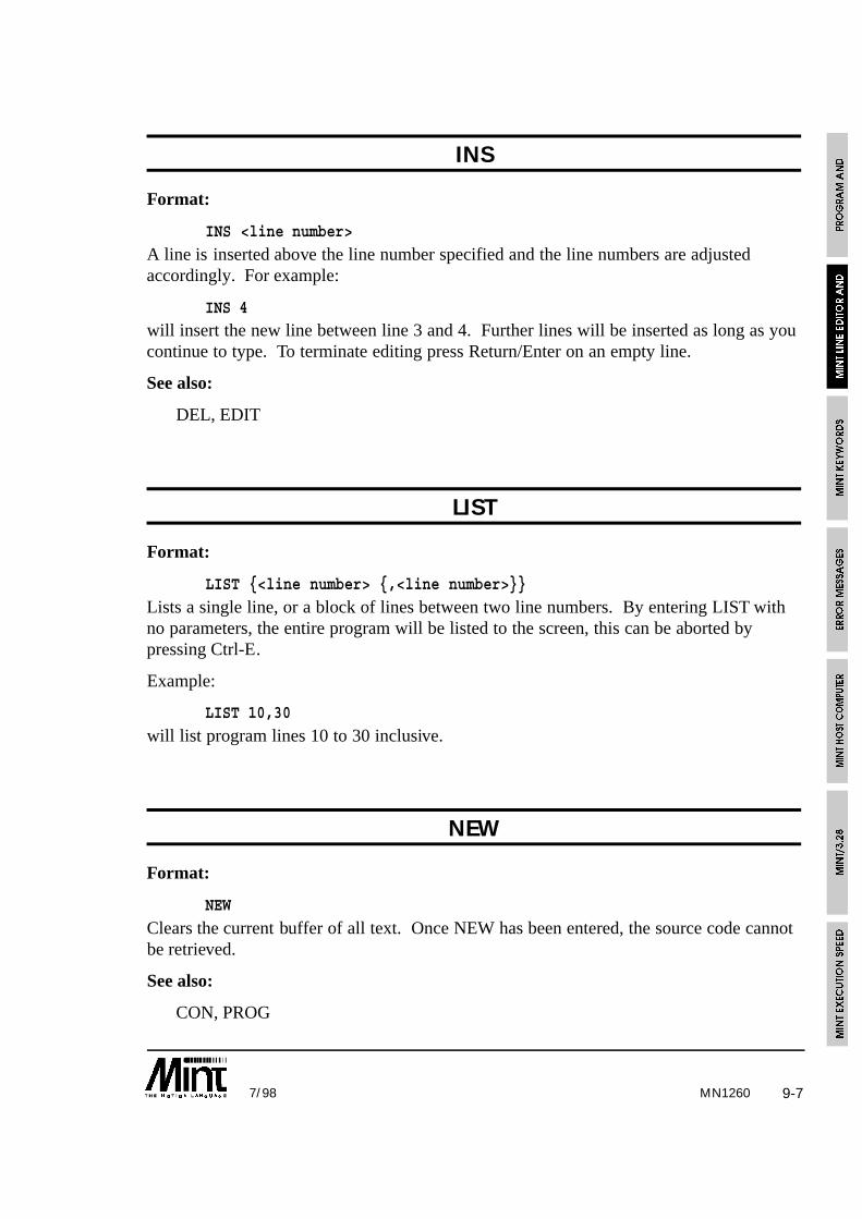
MN1260 9-77/98
INS
Format:
INS <line number>
A line is inserted above the line number specified and the line numbers are adjustedaccordingly. For example:
INS 4will insert the new line between line 3 and 4. Further lines will be inserted as long as youcontinue to type. To terminate editing press Return/Enter on an empty line.
See also:
DEL, EDIT
LIST
Format:
LIST {<line number> {,<line number>}}
Lists a single line, or a block of lines between two line numbers. By entering LIST withno parameters, the entire program will be listed to the screen, this can be aborted bypressing Ctrl-E.
Example:
LIST 10,30
will list program lines 10 to 30 inclusive.
NEW
Format:
NEW
Clears the current buffer of all text. Once NEW has been entered, the source code cannotbe retrieved.
See also:
CON, PROG
MN12609-8 7/98
PROG
Format:
PROG
Selects the program file for editing. The command line prompt will change to ‘P>’ andthe number of bytes used by the program file will be displayed:
Card #0Program: 23179 Bytes Free (3821 Used) 263 lines
Variables: #16 Arrays: #0
See also:
CON, FREE, NEW

MN1260 10-17/98
10. MINT Keywords
$ (Select Controller)
Purpose:
To select controllers over a multi-drop link
Format:
$<card>
$ is used to select a controller over the multi-drop link giving access to the fullfunctionality of the controller. $ must be followed by the card address which is 0 to 9 andA to F (for cards 10 to 15), where the card address is defined by the 4 way dip switcheson the controller. Once a card is selected, you have full access to the command line etc.allowing programs and data to be uploaded and downloaded. If protected communicationsis running (see COMMSON), the comms protocol must be aborted first before Ctrl-E canbe used.
Example:
$1
will select card 1
$B
will select card 11 (note the use of capital B, lower case b will not change the cardaddress).
$ is a form of immediate command only and thereforecannot be used within a program
See also:
CARD
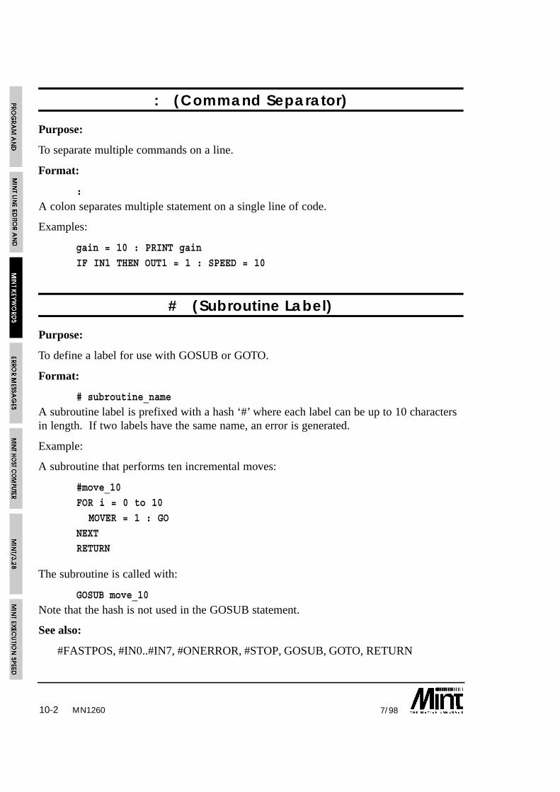
MN126010-2 7/98
: (Command Separator)
Purpose:
To separate multiple commands on a line.
Format:
:
A colon separates multiple statement on a single line of code.
Examples:
gain = 10 : PRINT gain
IF IN1 THEN OUT1 = 1 : SPEED = 10
# (Subroutine Label)
Purpose:
To define a label for use with GOSUB or GOTO.
Format:
# subroutine_name
A subroutine label is prefixed with a hash ‘#’ where each label can be up to 10 charactersin length. If two labels have the same name, an error is generated.
Example:
A subroutine that performs ten incremental moves:
#move_10
FOR i = 0 to 10
MOVER = 1 : GO
NEXTRETURN
The subroutine is called with:
GOSUB move_10
Note that the hash is not used in the GOSUB statement.
See also:
#FASTPOS, #IN0..#IN7, #ONERROR, #STOP, GOSUB, GOTO, RETURN

10-37/98
#FASTPOS
Purpose:
To define an interrupt routine that is called in response to a fast interrupt.
Format:
#FASTPOS...RETURN
Defines an interrupt routine on the fast interrupt input pin. The interrupt routine is calledon a rising edge (a transition of 0 to 1 as seen by the controller – inactive to active state)of the input. The fast interrupt will also latch the instantaneous axis positions and storethe values to the FASTPOS keyword. The routine can be disabled using the DINTkeyword and re-enabled using EINT.
In addition to latching the axis positions, the interrupt will also latch the encoder values tothe FASTENC keyword.
See the section 5.3.2.1 for more details.
See also:DINT, EINT, FASTENC, FASTPOS, #IN0..#IN7, RETURN
#IN0 .. #IN7 (User Interrupts)
Purpose:
To define an interrupt routine on a digital input.
Format:
#INx
Defines an interrupt routine on a digital input (IN0 to IN7). The interrupt routine is calledon a falling edge (a transition of 1 to 0 as seen by the controller – active to inactive state)of the input. See the section 5.3.3 for more details.
Example:
#IN3STOP.0PAUSE IDLE.0
RETURN
will stop any motion on axis 0 if a falling edge is seen on interrupt 3.
See also:IN0..IN7, RETURN
MN1260

10-4 7/98MN1260
#ONERROR
Purpose:
To define an error subroutine that is called in response to a motion error.
Format:
#ONERROR
Whenever there is a system error, MINT looks for a subroutine called #ONERROR (notethe use of the # as in a normal subroutine). If such a subroutine exists, MINT executes it.System errors can be either positional (following errors) or limit errors as shown in thetable:
Error Number Constant Error
1 _abort Software Abort
2 _maxfe Following Error
3 _limit Limit Error
11 _external External
13 Digital output(s) in error.SmartMove only
Limits can be disabled using the DISLIMIT keyword so that powered movement can beundertaken while beyond the limits. This should only be undertaken while under operatorsupervision. ENLIMIT or RESET will enable the limits.
This routine is used to recover from the error and put the controller back into a desiredstate.
Example:
#ONERROR
RESET[0,1,2]
RUN
This example program fragment resets the controller and re-runs the program in the eventof a motion error. Since ONERROR is a subroutine, it could be terminated by a RETURNstatement. In this event, the program would resume execution after the line where theerror occurred.
See sections 5.3.1.1 and 8 for further details.
See also:
CANCEL, DISLIMIT, ENLIMIT, ERROR, LIMIT, RETURN, RUN

10-57/98
#STOP
Purpose:
To define a STOP subroutine that is called in response to a stop input.
Format:
#STOP
Subroutine called in response to a rising edge (a transition of 0 to 1 as seen by thecontroller – inactive to active state) on the stop input. This can be used to halt programexecution and set some inputs etc. on a stop input.
Example:
#STOP
PAUSE !STOPSW : REM Wait for stop input
RETURN : REM Resume execution
Should the STOP subroutine terminate before the stop input is de-activated, the STOPsubroutine will not be called until another rising edge is seen.
See section 5.3 for more details on MINT interrupt routines.
See also:
RETURN, STOPMODE, STOPSW
ABORT/AB
Purpose:
To abort motion on all axes.
Format:
ABORT
MN1260

10-6 7/98MN1260
Abbr. Read Write Command Multi-Axis Scaled Default Range
AB ❑ – –
Firmware Version Motor Type
Process MINT Interpolation MINT/3.28 Servo Stepper
❑ ❑ ❑ ❑ ❑
Controller
ES/D ES/S ES/M3 SMS/1 SMS/2 SMS/3 SST/3 ESTE/D ESTE/S
❑ ❑ ❑ ❑ ❑ ❑ ❑ ❑ ❑
Abort motion - crash stop all axes - does not accept an axis parameter since it causesautomatic shut-down on all axes. The ERROR keyword will return 1 and the LED displaywill show an E. If the ONERROR routine is defined then this will be called.
ABORT
will abort motion on all axes.
Alternatively, the enable output can be turned off using the ENABLE keyword which doesnot result in an error.
See also:
CANCEL, ENABLE, ERROR, #ONERROR, RESET, STOP
ABS
Purpose:
To return the absolute value of an expression.
Format:
v = ABS(<expression>)
Calculates the absolute value of the expression.
Example:
PRINT ABS(7 * -5)will print 35 to the operator terminal.
Some keywords such as FOLERR and VEL return a signed number. To check that thevelocity is greater than a certain value regardless of motor direction the following wouldbe used:
IF ABS(VEL) > 20 THEN OUT4 = 1

10-77/98 MN1260
this will set output bit 4 if the velocity is greater than 20 or less than -20.
See also:
INT
ACCEL/AC
Purpose:
To define the acceleration of an axis.
Format:
ACCEL[axes] = <expression> {,<expression> ...}
v = ACCEL[axis]
Abbr. Read Write Command Multi-Axis Scaled Default Range
AC ❑ ❑ ❑ ❑ 300,000 1000.0 to3000 (step) 8388607.0
Firmware Version Motor Type
Process MINT Interpolation MINT/3.28 Servo Stepper
❑ ❑ ❑ ❑ ❑
Controller
ES/D ES/S ES/M3 SMS/1 SMS/2 SMS/3 SST/3 ESTE/D ESTE/S
❑ ❑ ❑ ❑ ❑ ❑ ❑ ❑ ❑
ACCEL sets the acceleration of the velocity profile in counts/s2. The acceleration can bechanged at any time during a move.
In an interpolated move the acceleration will determine the acceleration on the vector ofmovement. In order for correct motion, all axes performing interpolation must have thesame acceleration specified before the move is executed.
The DECEL keyword sets the deceleration value. The ACCEL keyword will override theDECEL keyword unless bit 0 of AXISCON is set.
The ACCEL/DECEL values determine the acceleration/deceleration rate when the STOPinput is opened. This will allow the system to come safely to rest.

10-8 7/98
Example:
SCALE = 2000;
ACCEL = 500;will set the acceleration rate, for the default axes, to 500 * 2000 counts / sec2.
During positional moves, theacceleration and deceleration can besmoothed out by using the RAMPkeyword. The effect of RAMP on theacceleration and deceleration ramps isshown in the diagram:
To set an acceleration rate higher than8388607 counts/sec2, use theACCELTIME keyword. This definesthe time taken to reach the velocity setby the SPEED keyword.
Note: Due to the resolution and representation of numbers in MINT it is notalways possible to store the exact value of ACCEL. When writing to ACCEL,
the value is converted from units per second to counts per servo loop.This can lead to rounding errors.
See also:
ACCELTIME, AXISCON, CIRCLEA, CIRCLER, DECEL, JOG, MOVEA, MOVER, RAMP, SCALE, SPEED, STOP, VECTORA, VECTORR
ACCELTIME/AT
Purpose:
To set an acceleration for position moves based on the time to reach a specified speed.
Format:
ACCELTIME[axes] = <expr> {,<expr> ...}
MN1260

10-97/98 MN1260
Abbr. Read Write Command Multi-Axis Scaled Default Range
AT ❑ ❑ ❑ – 2 to32000
Firmware Version Motor Type
Process MINT Interpolation MINT/3.28 Servo Stepper
❑ ❑ ❑ ❑ ❑
Controller
ES/D ES/S ES/M3 SMS/1 SMS/2 SMS/3 SST/3 ESTE/D ESTE/S
❑ ❑ ❑ ❑ ❑ ❑ ❑ ❑ ❑
The ACCELTIME keyword is used to define the time, in milli-seconds, to reach a velocitydefined by SPEED assuming a trapezoidal ramp (RAMP = 0).
Example:
SPEED = 20ACCELTIME = 50
the axis will accelerate to a speed of 20units/sec in 50 milli-seconds.
The acceleration, as defined byACCELTIME, is based on the currentSPEED when ACCELTIME was set.Therefore, if the SPEED is changed,the actual acceleration will remainconstant as shown in the diagram.ACCELTIME is based on a trapezoidalramp (RAMP = 0). The acceleration is also not defined by an ACCELTIME and JOGspeed, since ACCELTIME is based on the current SPEED setting.
ACCELTIME can be used to define higher accelerations than with the ACCEL keyword.It should be noted that if an ACCELTIME defines an acceleration higher than themaximum range allowed by ACCEL, reading ACCEL will return meaningless results.
ACCELTIME will also set the deceleration value unless bit 0 of the AXISCON keyword isset.
See also:
ACCEL, AXISCON, CIRCLEA, CIRCLER, DECEL, JOG, MOVEA, MOVER,RAMP, SCALE, SPEED, STOP, VECTORA, VECTORR

10-10 7/98MN1260
9Available only on 3 axis servo controller
ANALOGUE1/A1ANALOGUE2/A2
ANALOGUE3/A3*
Purpose:
To read the 10 bit analog inputs.
Format:v = ANALOGUE1V = ANALOGUE2V = ANALOGUE3
Abbr. Read Write Command Multi-Axis Scaled Default Range
A1 ❑ – 0 toA2 1023A39
Firmware Version Motor Type
Process MINT Interpolation MINT/3.28 Servo Stepper
❑ ❑ ❑ ❑ ❑
Controller
ES/D ES/S ES/M3 SMS/1 SMS/2 SMS/3 SST/3 ESTE/D ESTE/S
❑ ❑ ❑ ❑ ❑ ❑ ❑ ❑ ❑
Returns the value of the specified analog input. Each input has a ±10V or 0 to 5V rangewhich is jumper selectable, with 10 bit conversion resolution. See the hardwareinstallation manual for further details.
The analog ports can be used to provide XY control through a joystick (see section6.12.1).
Example:
JOG = ANALOGUE1-512,ANALOGUE2-512
this will jog both X and Y at a speed specified by the analog inputs. ANALOGUE1-512will return a value of -512 to 512.
ANALOGUE3 is only available on the 3 axis servo controller.
See also:
DAC

10-117/98 MN1260
AND/&
Purpose:
To perform a logical or bitwise AND.
Format:
v = <expr> AND <expr>
Abbreviation:
&Logical AND used in conditional statements and loops, for example:
IF key = ‘A’ AND userEnable THEN GOSUB setup
“GOSUB setup” is only executed if both key = ‘A’ and userEnable are true.
Logical AND is based on the following truth table:
<expr1> <expr2> <expr1> AND <expr2>
0 0 0
0 1 0
1 0 0
1 1 1
AND is a bitwise logical operator and can be used to mask bits on outputs for example:
OUT = OUT & 15
will clear bits 4 to 7 leaving bits 0 to 3 intact.
IF IN & 010101010 THEN OUT1 = 1will set output bit 1 if any of the even input bits are active.
See also:
NOT, OR

10-12 7/98
AUTO
Purpose:
To automatically execute a program on power up.
Format:
AUTO
AUTO causes the program within the controllers non-volatile RAM to be executedautomatically on power-up. AUTO must be the first command in the configuration file. IfAUTO is found anywhere else in either files, it will be ignored. Once this is set the onlyway to regain user control is by sending 05H down the master serial port (press Ctrl-E atthe keyboard). Ctrl-E will cause the interpreter to return to immediate mode at any timeduring code execution. If MINT Host Computer Communications (COMMSON) isenabled, a special data packet must be sent to the controller to abort the comms protocolbefore Ctrl-E is interpreted.
AUTO
REM Set system defaults
RESET[0,1,2]
KVEL = 10;GAIN = 2;
KINT = .1;
SCALE = 1000
...
If protected datapackets are sent the controller before it has powered up,there is the danger that Ctrl-E within a data packet could result in the
program termination. In order to minimize this risk, COMMSON shouldbe placed immediately after AUTO.
See also:
COMMSON, RUN
MN1260

10-137/98 MN1260
AUX/AX
Purpose:
To enable system commissioning by writing the velocity or following error to a DACoutput.
Format:
AUX = <expr>
v = AUX
Abbr. Read Write Command Multi-Axis Scaled Default Range
AX ❑ ❑ ❑ – –1 to 5
Firmware Version Motor Type
Process MINT Interpolation MINT/3.28 Servo Stepper
❑ ❑ ❑ ❑
Controller
ES/D ES/S ES/M3 SMS/1 SMS/2 SMS/3 SST/3 ESTE/D ESTE/S
❑ ❑ ❑ ❑ ❑ ❑
The AUX keyword enables the axis velocity or following to be written to another DACoutput on the controller for system commissioning. If a 3 axis servo controller is used, thevelocity or following error is written to the 4th DAC output. The AUX keyword acceptsone of the following values:
Value Action
-1 Disable function
0 Write velocity of axis 0 to DAC output 1 or 4th DAC
1 Write velocity of axis 1 to DAC output 0 or 4th DAC
2 Write velocity of axis 2 to DAC output 0 or 4th DAC
3 Write following error of axis 0 to DAC output 1 or 4th DAC
4 Write following error of axis 1 to DAC output 0 or 4th DAC
5 Write following error of axis 2 to DAC output 0 or 4th DAC

10-14 7/98
Using an oscilloscope on the DAC output, the axis can be tuned for the best systemresponse. Writing the velocity to the DAC output will show the velocity profile of anypositional move highlighting any overshoot or instability. In order to monitor the velocityprofile, short positional moves with high accelerations and speeds are advised. Thevelocity is shown as counts per servo loop.
Writing to the AUX keyword on axis 2will direct the following error andvelocity of axes 0 and 1 to the thirdaxis option board. For example:
AUX.2 = 1
will direct the velocity of axis 1 to theDAC output on the third axis optionboard. If the AXES keyword is used todefault to axis 2 (AXES[2]) thefollowing must be used to direct theoutput to either axis 0 or axis 1:
AUX.0 = 3
will direct the following error of axis 0to the DAC output on axis 1.
The following error can be reducedconsiderably by applying some velocityfeedforward gain, KVELFF (see theGetting Started Guide for furtherdetails). This can be monitored, usingan oscilloscope, by writing thefollowing error out to the DAC output (AUX = 3 to 5).
Note that given a 12 bit DAC, the maximum following error and velocity that can beshown is +/- 2048 counts.
Remember to disable the AUX keyword (AUX = -1) beforeconnecting the other motor.
For SmartMove, SmartSystem/3 and EuroServo, the following errorand velocity are directed to the 4th analog output.
See also:
AUXDAC, CAPTURE, GAIN, FOLERR, KINT, KVEL, KVELFF, VEL
MN1260

10-157/98 MN1260
AUXDAC/AD
Purpose:
To write an analog value to the 4th DAC output on SmartMove, SmartSystem/3 orEuroServo/3.
Format:
AUXDAC = <expr>
v = AUXDAC
Abbr. Read Write Command Multi-Axis Scaled Default Range
AD ❑ ❑ – –1 to 5
Firmware Version Motor Type
Process MINT Interpolation MINT/3.28 Servo Stepper
❑ ❑ ❑ ❑
Controller
ES/D ES/S ES/M3 SMS/1 SMS/2 SMS/3 SMM/1 SMM/2 SMM/3 SST/3 ESTE/D ESTE/S
❑ ❑ ❑ ❑ ❑
The AUXDAC keyword is used to write directly to the 4th 12 bit DAC output. AUXDACaccepts a value of -2047 (-10V) to 2047 (+10V) where an increment of 1 represents4.9mV.
Example:
AUXDAC = 1024
will give a 5V output on the DAC.
If the AUX keyword has been used, this must be assigned a value of -1 to disable thisfunction since it will overwrite any value written to the 4th DAC output by the AUXDACkeyword.
Reading AUXDAC will return the value written to the DAC output.
See also:
AUX, AUXDAC, DAC

10-16 7/98MN1260
AXES
Purpose:
To define a default axis string.
Format:
AXES[axis list]
Abbr. Read Write Command Multi-Axis Scaled Default Range
– ❑ ❑ – –
Firmware Version Motor Type
Process MINT Interpolation MINT/3.28 Servo Stepper
❑ ❑ ❑ ❑
Controller
ES/D ES/S ES/M3 SMS/1 SMS/2 SMS/3 SST/3 ESTE/D ESTE/S
❑ ❑ ❑ ❑ ❑ ❑ ❑ ❑ ❑
Defines the default axis string for commands and writable motion variables.
Example:
AXES[1,2]
MOVEA = 20,30 : GO
Executes absolute move on axes 1 and 2.
This is the same as:
MOVEA[1,2] = 20,30 : GO[1,2]
Once the default axis string is defined, the first example will be quicker to execute thanthe second, as well as taking up less program space.
Typing AXES at the command line will display the current axis string.

10-177/98 MN1260
10Abbreviation supported by MINT/3.28 only
AXISCON
Purpose:
To set-up an axis configuration
Format:
AXISCON[axes] = <expr> {,<expr> ...}
v = AXISCON[axis]
Abbr. Read Write Command Multi-Axis Scaled Default Range
AO10 ❑ ❑ ❑ ❑ 0 to 255
Firmware Version Motor Type
Process MINT Interpolation MINT/3.28 Servo Stepper
❑ ❑ ❑ ❑
Controller
ES/D ES/S ES/M3 SMS/1 SMS/2 SMS/3 SMM/1 SMM/2 SMM/3 SST/3 ESTE/D ESTE/S
❑ ❑ ❑ ❑ ❑ ❑ ❑ ❑ ❑ ❑ ❑ ❑
AXISCON is used to switch in and out various axis attributes such as DECEL and the 3channel encoder interface board. AXISCON accepts a bit mask, a setting of 0 on the bitturns off the attribute and a setting of 1 turns it on. The following bits are defined:
Bit Description
0 Turn on the DECEL keyword. A setting of 0 will allow the ACCEL valueto over-write the DECEL value. This allows backwards compatibility ofMINT programs before the DECEL keyword was introduced.
1 Turn on the 3 channel encoder interface. This allows the use of theXENCODER keyword. Turning it off (default) provides MINT with moreexecution time.
2 Turn off following error detection for the axis. If the maximum followingerror is exceeded (MFOLERR), no error will be given and the followingerror value will be set to MFOLERR.
3 When set, MOVER returns the target position rather than final position.
4..7 Reserved for future use.
10-18 7/98MN1260
Example:
AXISCON.1 = 011
Turns on the DECEL keyword and XENCODER for axis 1.
See also:
ACCEL, DECEL, FOLLOWAXIS, MFOLERR, XENCODER
BACKOFF/BA
Purpose:
To set the home backoff speed factor.
Format:
BACKOFF[axes] = <expression> {,<expression> ...}
v = BACKOFF[axis]
Abbr. Read Write Command Multi-Axis Scaled Default Range
BA ❑ ❑ ❑ 10 1 to 100
Firmware Version Motor Type
Process MINT Interpolation MINT/3.28 Servo Stepper
❑ ❑ ❑ ❑ ❑
Controller
ES/D ES/S ES/M3 SMS/1 SMS/2 SMS/3 SST/3 ESTE/D ESTE/S
❑ ❑ ❑ ❑ ❑ ❑ ❑ ❑ ❑
BACKOFF determines the backoff speed from a home switch. The home sequence isexplained in section 6.4. The axis will reverse from the home switch at:
HMSPEED/BACKOFF
BACKOFF by default is set to 10. Reducing this value will decrease the time taken toperform the homing sequence, especially when a slow HMSPEED is used.

10-197/98 MN1260
Example:
BACKOFF = 2;
HMSPEED = 2000;HM = 0;
PAUSE IDLE[0,1,2]
will backoff from the home switch at a speed of 1000 counts/sec.
See also:
HMPSEED, HOME
BAUD
Purpose:
To set the serial port baud rate.
Format:
BAUD = <expr>
Abbr. Read Write Command Multi-Axis Scaled Default Range
– ❑ 9600 300 to 19200
Firmware Version Motor Type
Process MINT Interpolation MINT/3.28 Servo Stepper
❑ ❑ ❑ ❑
Controller
ES/D ES/S ES/M3 SMS/1 SMS/2 SMS/3 SMM/1 SMM/2 SMM/3 SST/3 ESTE/D ESTE/S
❑ ❑ ❑ ❑ ❑ ❑ ❑ ❑ ❑ ❑ ❑ ❑
The BAUD keyword is used to set the controllers serial port data rate. By default, thecontroller will power up with a baud rate setting of 9600. This can be overwritten byplacing BAUD in the configuration file. This should be place near the beginning beforeany terminal I/O commands. For example:
AUTOBAUD = 1200 : REM 1200 bits per secondAXES[0,1,2]RESETSCALE = 100,200,300...

10-20 7/98
Note that MINT will accept any value of BAUD between the range of 300 and 19,200 andis not restricted to common baud rates such as 1200, 2400, 4800 etc.
BEEP
Purpose:
To issue a beep at the user terminal.
Format:
BEEPIssues a beep at the user terminal. This is useful to attract the attention of an operator. Ifa keypad and display is connected, the keypad buzzer will sound.
Example:
#ONERROR
CLS
? “*** ERROR ***”
REM Beep to attract attention until a key press
REPEAT
BEEP : WAIT = 200
UNTIL INKEYRESET[0,1,2]
RUN
See also:
BEEPOFF, BEEPON, CHR
MN1260

10-217/98
BEEPOFF
Purpose:
To disable the keypad buzzer during INPUT and INKEY. This is the default mode onpower up.
Format:
BEEPOFF
Disable the keypad buzzer during INPUT and INKEY. For example:
BEEPOFF
INPUT a USING 5,2
No beep will be emitted when a key is pressed unlike:
BEEPON
INPUT a USING 5,2
See also:
BEEP, BEEPON, INKEY, INPUT
BEEPON
Purpose:
To enable the keypad buzzer during INPUT and INKEY.
Format:
BEEPON
To provide a form of tactile feedback from the keypad, BEEPON will cause INPUT andINKEY to issue a beep when a key is pressed. Note that on power up, the controller willdefault to BEEPOFF.
Example:
BEEPON
INPUT a USING 5,2
BEEPOFF
A beep will be emitted from the keypad buzzer every time a key is pressed.
See also:
BEEP, BEEPOFF, INKEY, INPUT
MN1260

10-22 7/98
BINARY
Purpose:
To display an 8 bit binary number.
Format:
BINARY argument list
The BINARY keyword has the same syntax as PRINT except numbers are printed inbinary. All numbers are stripped of their fractional part.
Example:
BINARY “12 in binary is : “,12will print:
12 in binary is : 00001100
Numbers will be printed up to 8 bits in length and are prefixed with zeroes wherenecessary. BINARY is useful for reading the digital inputs:
BINARY IN
See also:
BOL, LOCATE, PRINT
BOL
Purpose:
To move the cursor to the beginning of the line.
Format:
BOL
Return the cursor to the Beginning Of Line without feeding a new line. Useful forrepeatedly printing a position (POS) or velocity (VEL) at a terminal on a single line.
Example:
LOOP : ? POS[0]; : BOL : ENDL
Note the use of the semicolon after PRINT to suppress line feeding and to clear anycharacters to the next tab stop.
See also:
LINE, LOCATE, PRINT
MN1260

10-237/98 MN1260
BOOSTOFF/BF
Purpose:
To turn the stepper boost output off.
Format:
BOOSTOFF[axes]
Abbr. Read Write Command Multi-Axis Scaled Default Range
BF ❑ ❑ – –
Firmware Version Motor Type
Process MINT Interpolation MINT/3.28 Servo Stepper
❑ ❑ ❑
Controller
ES/D ES/S ES/M3 SMS/1 SMS/2 SMS/3 SST/3 ESTE/D ESTE/S
❑ ❑ ❑ ❑ ❑
Some stepper drives have a boost input to increase the power to the stepper motor, issuingBOOSTOFF turns the stepper boost output off. If the boost is not used, the output can beused as a general output. This will give the you up to 3 extra outputs.
Example:
BOOSTOFF[1,2]
will turn boost outputs 1 and 2 off.
On power up, the default is BOOSTOFF.
See also:
BOOSTON, OUT

10-24 7/98MN1260
BOOSTON/BO
Purpose:
To turn the stepper boost output on.
Format:
BOOSTON[axes]
Abbr. Read Write Command Multi-Axis Scaled Default Range
BO ❑ ❑ – –
Firmware Version Motor Type
Process MINT Interpolation MINT/3.28 Servo Stepper
❑ ❑ ❑
Controller
ES/D ES/S ES/M3 SMS/1 SMS/2 SMS/3 SST/3 ESTE/D ESTE/S
❑ ❑ ❑ ❑ ❑
Some stepper drives have a boost input to increase the power to the stepper motor, issuingBOOSTON turns the stepper boost output on. If the boost is not used, the output can beused as a general output. This will give the you up to 3 extra outputs.
Example:
BOOSTON[0,1]
will turn boost outputs 0 and 1 on.
On power up, the default is BOOSTOFF.
See also:
BOOSTOFF, OUT

10-257/98 MN1260
11Axes 0 and 1 only
CAM/CMCAMA
Purpose:
To begin a cam profile of a table of points which can be defined relatively or absolutely.
Format:
CAM[axes] = <expr> {,<expr> }
v = CAM[axis]
Abbr. Read Write Command Multi-Axis Scaled Default Range
CM ❑ ❑ ❑11 – 0 to 7
Firmware Version Motor Type
Process MINT Interpolation MINT/3.28 Servo Stepper
❑ ❑
Controller
ES/D ES/S ES/M3 SMS/1 SMS/2 SMS/3 SST/3 ESTE/D ESTE/S
❑ ❑ ❑ ❑ ❑ ❑
The CAM keyword will begin motion on the cam table defined by the cam0 variable foraxis 0 and cam1 for axis 1. For example:
DIM cam0(10) = 9,10,20,30,40,50,40,30,20,10
The first element in the table defines the number of segmentsused to make up the cam.
The cam table can be made up of relative positions or absolute positions within the camprofile. The nature of the positions is given by command used to start cam profiling. TheCAM command interprets the values in the table as relative values. The CAMA commandinterprets the values as absolute positions within one cam cycle.
A cam can be defined to execute once as follows:
CAM.0 = 0
10-26 7/98MN1260
or indefinitely
CAM.0 = 1
The CAMA/CAM keywords accept one of the following values:
CAM Value Function
0 One shot cam
1 Continuous cam. Cam table restarts when end is reached
2 One shot cam triggered by a fast interrupt.
3 Continuous cam. Triggered by a fast interrupt.Successive fast interrupts will reset the cam.
+4 Adding 4 to the CAMA keyword will reference allabsolute positions to the motor position and not the cam.
Reading the CAM keyword will return the currently executing cam segment size. Thecurrent segment or index in the cam table is read using the CAMINDEX keyword. Forexample:
CAM.1 = 0PAUSE CAMINDEX.1 = 10
OUT1 = 1
PAUSE CAMINDEX.1 = 12
OUT1 = 0
will execute a cam on axis 1. When the 10th cam point is executed, output bit 1 is set.The output is cleared on the 12th cam point.
The cam profile is linked to the master position by the MASTERINC keyword. Forexample:
MASTERINC = 1000
the slave will move the distance given by a cam segment in the cam table for every 1000counts of the master. The master can be defined as the encoder of another axis, the pulsefollower input or a fixed speed. This is given by the FOLLOWAXIS keyword. A table ofdifferent master increments can be set-up in the minc0 variable (minc1 for axis 1). Forexample:
DIM minc0(10) = 100,200,100,200,100,200,100,200,100,200
the positions in the table are defined in relative terms. The number of positions mustequal the number of positions in the cam table. The master increment table will overridethe MASTERINC keyword.

10-277/98
Notes:
• The first element in the cam table defines the number of cam segments. This allowsfor greater flexibility in defining different tables.
• When a CAM command is executed, the status display will show a small ‘c’ andMODE will return 16.
• Assigning a value of 0 to a cam segment will cause the slave to wait the measureddistance on the master.
• It is assumed that the master is moving in one direction only.
• Absolute cams have a starting position of 0 within the cam cycle.
• If the MASTERINC value is less than the maximum master input speed (per servoloop closure), the cam will not execute correctly. Ideally the MASTERINC valueshould be at least 5 times the master speed i.e. a cam segment will be executed over 5servo loops. For example:
• Maximum master input speed is 60000 counts per second. With a 2ms loop closuretime, the speed per servo loop is 60000/500 = 120 counts. This would make aminimum MASTERINC value of 600 counts.
• Multiple cam tables can be defined using the CAMSTART and CAMEND keywords.
• Cam profiling is applicable only to axes 0 and 1.
See section 6.7 for further details on cam profiling.
See also:
CAMEND, CAMINDEX, CAMSTART, FLY, FOLLOWAXIS, GEARN, GEARD,MASTERINC, MOVECAM
MN1260
10-28 7/98MN1260
12Axes 0 and 1 only
CAMINDEX/CI
Purpose:
To return the currently executing cam segment index
Format:
v = CAMINDEX[axis]
Abbr. Read Write Command Multi-Axis Scaled Default Range
CI ❑ ❑12 – –
Firmware Version Motor Type
Process MINT Interpolation MINT/3.28 Servo Stepper
❑ ❑
Controller
ES/D ES/S ES/M3 SMS/1 SMS/2 SMS/3 SST/3 ESTE/D ESTE/S
❑ ❑ ❑ ❑ ❑ ❑
When cam profiling is performed on a cam table, the currently executing segment in thetable can be read using the CAMINDEX keyword.
Example:
DIM cam0(11) = 10,20,30,40,50,60,50,40,20,20,10
The value in the table can be read as follows:
? cam0( CAMINDEX.0 + 1)
Note that one is added to take into account the first parameter of the cam table which isused to set-up the number of cam segments.
See also:
CAM, CAMEND, CAMSTART

10-297/98 MN1260
13Axes 0 to 1 only
CAMEND/CE
Purpose:
To define an end point in the cam table if multiple cams are required.
Format:
CAMEND[axes] = <expr> {,<expr>}
v = CAMEND[axis]
Abbr. Read Write Command Multi-Axis Scaled Default Range
CE ❑ ❑ ❑13 – 1 to 6000
Firmware Version Motor Type
Process MINT Interpolation MINT/3.28 Servo Stepper
❑ ❑
Controller
ES/D ES/S ES/M3 SMS/1 SMS/2 SMS/3 SST/3 ESTE/D ESTE/S
❑ ❑ ❑ ❑ ❑ ❑
By default the number of cam points in a cam table is given by the first element in thecam table. If multiple cams are required, the start and end positions in the cam can bedefined. For example:
CAMSTART.0 = 10
CAMEND.0 = 20DIM cam0(21) = 0,10,20,30,40,50,60,70,80,90,100,
100,90,80,70,60,50,40,30,20,10
Note that the first element in the cam table is given as 0. This instructs MINT to use theCAMEND keyword to define the last element in the cam table. The CAMSTARTkeyword is used to define the start element for the cam. Therefore, for the aboveexample, a cam profile will be based on cam segments 10 to 20 (values 100 to 10).
Note that it is assumed that the first element has an array index value of 0, and the camsegment values start at 1. The actual start cam segment value will be given by:
v = cam0( CAMSTART.0 + 1)
CAMEND only applies to axes 0 and 1.

10-30 7/98MN1260
14Axes 0 and 1 only
See also:
CAM, CAMA, CAMINDEX, CAMSTART
CAMSTART/CS
Purpose:
To define a start point in the cam table if multiple cams are required.
Format:
CAMSTART[axes] = <expr> {,<expr>}v = CAMSTART[axis]
Abbr. Read Write Command Multi-Axis Scaled Default Range
CS ❑ ❑ ❑14 – 1 to 6000
Firmware Version Motor Type
Process MINT Interpolation MINT/3.28 Servo Stepper
❑ ❑
Controller
ES/D ES/S ES/M3 SMS/1 SMS/2 SMS/3 SST/3 ESTE/D ESTE/S
❑ ❑ ❑ ❑ ❑ ❑
By default the number of cam points in a cam table is given by the first element in thecam table. If multiple cams are required, the start and end positions in the cam can bedefined. For example:
CAMSTART.0 = 10CAMEND.0 = 20
DIM cam0(21) = 0,10,20,30,40,50,60,70,80,90,100,
100,90,80,70,60,50,40,30,20,10
Note that the first element in the cam table is given as 0. This instructs MINT to use theCAMEND keyword to define the last element in the cam table. The CAMSTARTkeyword is used to define the start element for the cam. Therefore, for the aboveexample, a cam profile will be based on cam segments 10 to 20 (values 100 to 10).

10-317/98 MN1260
Note that it is assumed that the first element has an array index value of 0, and the camsegment values start at 1. The actual start cam segment value will be given bycam0(CAMSTART.0 + 1).
See also:
CAM, CAMA, CAMEND, CAMSTART
CANCEL/CN
Purpose:
To cancel any errors but retain the current position.
Format:
CANCEL[axes]
Abbr. Read Write Command Multi-Axis Scaled Default Range
CN ❑ ❑ – –
Firmware Version Motor Type
Process MINT Interpolation MINT/3.28 Servo Stepper
❑ ❑ ❑ ❑ ❑
Controller
ES/D ES/S ES/M3 SMS/1 SMS/2 SMS/3 SST/3 ESTE/D ESTE/S
❑ ❑ ❑ ❑ ❑ ❑ ❑ ❑ ❑
CANCEL will clear any motion errors and the move in progress but retain the motorposition, unlike RESET. This can be used to recover from errors in an ONERROR routinewith the exception of limit errors. If a limit error exists and the limit is still active, issuinga CANCEL will not clear the error, use the DISLIMIT keyword instead.
CANCEL will also turn contouring off, and reset GEARN and GEARD to 0 and 1respectively. The following error (FOLERR) is set to zero.
On SmartMove, if the outputs are in error, CANCEL will clear all the digital outputs.

10-32 7/98MN1260
Example:
#ONERROR
REM We have a following errorIF ERROR.0 = _maxfe DO
CANCEL.0 : REM Cancel error
RETURN
ENDIF
RETURN
See also:
CONTON, DEFAULT, DISLIMIT, ERROR, FOLERR, LIMIT, #ONERROR, RESET
CAPTURE/CP
Purpose:
To determine what data is captured for future analysis and initiate data capture.
Format:
CAPTURE[axis] = <expr>
v = CAPTURE[axis]
Abbr. Read Write Command Multi-Axis Scaled Default Range
CP ❑ ❑ ❑ – 1 to 3
Firmware Version Motor Type
Process MINT Interpolation MINT/3.28 Servo Stepper
❑ ❑ ❑
Controller
ES/D ES/S ES/M3 SMS/1 SMS/2 SMS/3 SMM/1 SMM/2 SMM/3 SST/3 ESTE/D ESTE/S
❑ ❑ ❑ ❑ ❑ ❑ ❑ ❑
The CAPTURE keywords defines the source and axis of data to be capture and beginsdata capture. CAPTURE accepts a value of between 1 and 3. This corresponds to thefollowing data:

10-337/98 MN1260
Value Description
1 Capture the axis velocity
2 Capture the axis following error
3 Capture the axis position
CAPTURE can only capture one data source, one axis, at a time. The axis to capture isspecified by the axis parameter passed as follows:
CAPTURE.1 = 2
will capture the following error on axis 1.
Data capture is discussed in detail in section 7.5.
See also:
AUX, DATATIME
CARD/CD
Purpose:
To read the current card address on a RS485 controller.
Format:
v = CARD
Abbr. Read Write Command Multi-Axis Scaled Default Range
CD ❑ – 0 to 15
Firmware Version Motor Type
Process MINT Interpolation MINT/3.28 Servo Stepper
❑ ❑ ❑ n/a n/a
Controller
ES/D ES/S ES/M3 SMS/1 SMS/2 SMS/3 SST/3 ESTE/D ESTE/S
❑ ❑ ❑ ❑ ❑ ❑ ❑ ❑ ❑
Returns the card number (0 to 15). The card number is set by a series of DIP switches onthe controller card. See the hardware guide for more information.

10-34 7/98
In a multi-drop system, the CARD keyword can be useful for establishing the controllernumber.
See also:
$ (select controller)
CHR
Purpose:
To print non-ASCII characters. Used in conjunction with PRINT.
Format:
PRINT CHR(<expr>)
CHR is used within the PRINT statement to issue special characters to a terminalemulator.
Example:
PRINT CHR(7)
will issue a beep at the user terminal.
CHR is useful for sending Escape string to a terminal. For example:
PRINT CHR(27),”[1;1”,CHR(27),”[J”,
will home the cursor and clear the screen on a VT100 compatible terminal.
Note the use of the comma to suppress line feeding.
See also:
BINARY, LINE, PRINT
CIRCLEA/CA
Purpose:
To perform a circular move with absolute co-ordinates.
Format:
CIRCLEA[axis0,axis1] = <centre0>,<centre1>,<angle>
MN1260

10-357/98 MN1260
15Axes 0 and 1 only
Abbr. Read Write Command Multi-Axis Scaled Default Range
CA ❑ ❑15 ❑ – –8388607 to838867.0–360.0 to
360.0 (angle)
Firmware Version Motor Type
Process MINT Interpolation MINT/3.28 Servo Stepper
❑ ❑ ❑ ❑
Controller
ES/D ES/S ES/M3 SMS/1 SMS/2 SMS/3 SST/3 ESTE/D ESTE/S
❑ ❑ ❑ ❑ ❑ ❑ ❑ ❑
Absolute circular interpolation: Circular interpolation is only valid on axes 0 and 1.
<centre0> and <centre1> are absolute positions with the limitation that the positionaloffset must be less than 218. <angle> refers to the angular increment for the circular arc(±360.00o). Positive numbers refer to anti-clockwise motion. An out of range error isreturned if the calculated radius of motion is outside the range 10-218 quadrature countsor the offset from the current position is greater than 218. For example if the currentposition is 0,0, the following would be invalid (assuming SCALE = 1):
CIRCLEA = 40000,0,90 : GO
The command will be accepted during a current positional move but will not be executeduntil the next GO statement.
Example:
SPEED = 20,20CONTON
VECTORA = 80,20 : GO
CIRCLEA = 100,0,-90 : GO
PAUSE IDLE[0,1] : REM Wait for axes to stop beforeCONTOFF : REM Turning contouring off

10-36 7/98
Assuming a starting position of 40,-20,this executes a straight line segment onaxes 0 and 1 followed by a circular arc of90 degrees at constant speed of 20. Notethat it is imperative to set the axis speedsand accelerations to the same value beforeexecuting the move since these refer tospeeds and accelerations along the vectorof motion.
Notes:
Reading the keywords MOVEA or MOVER will return the final position of thecircular move.
Steppers motors will only accept a position offset of 215 and not 218
Reading the OFFSET keyword will return the remaining length of the move.
The minimum radius is 10 counts.
See also:
ACCEL, CIRCLER, CONTOFF, CONTON, GO, OFFSET, MODE, RAMP, SCALE, SPEED, VECTORA, VECTORR
MN1260

10-377/98 MN1260
16Axes 0 and 1 only
CIRCLER/CR
Purpose:
To perform a circular move with relative co-ordinates.
Format:CIRCLER[axis0,axis1] = <centre0>,<centre1>,<angle>
Abbr. Read Write Command Multi-Axis Scaled Default Range
CR ❑ ❑16 ❑ – –8388607 to838867.0–360.0 to
360.0 (angle)
Firmware Version Motor Type
Process MINT Interpolation MINT/3.28 Servo Stepper
❑ ❑ ❑ ❑
Controller
ES/D ES/S ES/M3 SMS/1 SMS/2 SMS/3 SST/3 ESTE/D ESTE/S
❑ ❑ ❑ ❑ ❑ ❑ ❑ ❑
Relative circular interpolation: Circular interpolation is only valid on axes 0 and 1.
<centre0> and <centre1> are relative to the current position. <angle> refers to theangular increment for the circular arc (±360.00o). Positive numbers refer to anti-clockwisemotion. An out of range error is returned if the calculated radius of motion is outside therange 10-218 quadrature counts. The command will be accepted during a currentpositional move but will not be executed until the next GO statement.
Example:
CR = 100,100,90 : GO
Example 2:
SPEED = 20,20
CONTONVECTORR = 40,40 : GO
CIRCLER = 20,-20,-90 : GO
PAUSE IDLE[0,1] : REM Wait for axes to stop before
CONTOFF : REM Turning contouring off
10-38 7/98
Assuming a starting position of 40,-20, thisexecutes a straight line segment on axes 0and 1 followed by a circular arc of 90degrees at constant speed of 20. Note that itis imperative to set the axis speeds andaccelerations to the same value beforeexecuting the move since these refer tospeeds and accelerations along the vector ofmotion.
Notes:
Reading the keywords MOVEA or MOVER will return the final position of thecircular move.
Steppers motors will only accept a maximum position offset of 215 and not 218
Reading the OFFSET keyword will return the remaining length of the move.
The minimum radius is 10 counts.
See also:
ACCEL, CIRCLEA, CONTOFF, CONTON, GO, OFFSET, MODE, RAMP, SCALE,SPEED, VECTORA, VECTORR
CLS
Purpose:
To clear a VT100 (or VT52) compatible or LCD screen.
Format:
CLS
Clear the terminal screen and the LCD display if connected. The cursor is placed in thetop left corner. CLS is VT100 compatible (TERM can be used to configure CLS for VT52terminal emulation).
Example:
CLS
? “Home Position”
See also:
LOCATE, TERM
MN1260

10-397/98
COMMSOFF
Purpose:
To turn protected communications protocol off.
Format:
COMMSOFF
Turns the protected communications protocol off allowing the serial port to be used tostandard I/O statements such as PRINT and INPUT.
See also:
COMMSON, DIM
COMMSON
Purpose:
To turn protected communications protocol on.
Format:
COMMSON
Turns the protected communications protocol on. COMMSON will make MINT aware ofprotected data packets. Issuing COMMSON will automatically define an array variableCOMMS which is 99 elements in length. This must be placed before any DIM statementsfor correct execution. For example:
COMMSONDIM xpos(100)
DIM ypos(100)
COMMSON will disable Ctrl-E until COMMSON is terminated by sending a special datapacket.
COMMSON cannot be issued at the command line.
Subsequent uses of COMMSON will turn the protected protocol on and can be used inconjunction with COMMSOFF to turns communications on and off from within theprogram.
See section 12 on protected communications for full details.
See also:
COMMSOFF, DIM
MN1260

10-40 7/98MN1260
CONFIG/CF
Purpose:
To configure an axis for different motor types or to turn an axis off.
Format:
CONFIG[axes] = <motor type> {,<motor type>}
v = CONFIG[axis]
Abbr. Read Write Command Multi-Axis Scaled Default Range
CF ❑ ❑ ❑ 1 0 to 4 (servo)2 0 to 3 (stepper)
Firmware Version Motor Type
Process MINT Interpolation MINT/3.28 Servo Stepper
❑ ❑ ❑ ❑ ❑
Controller
ES/D ES/S ES/M3 SMS/1 SMS/2 SMS/3 SST/3 ESTE/D ESTE/S
❑ ❑ ❑ ❑ ❑ ❑ ❑ ❑ ❑
Configures the axis for stepper or servo control. For example:
CONFIG[0,1,2] = _servo, _stepper, _off
This will configure axis 0 as a servo, axis 1 as a stepper and turn axis 2 off. CONFIG willalways issue a RESET and will reset the speeds and accelerations to their defaults. Thevalues accepted by CONFIG are:
Value Constant Motor Type
0 _off Turn the axis off
1 _servo Servo motor
2 _stepper Stepper motor
3 _micro Micro stepper
4 _inverter Inverter drive 0-10v plus direction

10-417/98 MN1260
The default values for the speeds and acceleration, expressed in Quad Counts/Steps, are:
Keyword Motor Type Default
SPEED servo/micro step 80000
SPEED stepper 1000
ACCEL servo/micro step 3000000
ACCEL stepper 3000
HMSPEED servo/micro step 20000
HMSPEED stepper 500
Turning an axis off (CONFIG = 0) will result in a 10% speed-up in the execution ofMINT programs. This is useful in a 1 or 2 axis system where the remaining axes are notused. With the axis turned off, its encoder position can still be read using either the POSor ENCODER keyword. The axis can also be followed using the FOLLOW keyword.
See also:
ACCEL, DIR, ENCODER, HMSPEED, POS, SPEED
CONTOFF/CO
Purpose:
To turn contouring off.
Format:
CONTOFF
Abbr. Read Write Command Multi-Axis Scaled Default Range
CO ❑ – –
Firmware Version Motor Type
Process MINT Interpolation MINT/3.28 Servo Stepper
❑ ❑ ❑ ❑ ❑
Controller
ES/D ES/S ES/M3 SMS/1 SMS/2 SMS/3 SST/3 ESTE/D ESTE/S
❑ ❑ ❑ ❑ ❑ ❑ ❑ ❑

10-42 7/98MN1260
Sets contouring off at the end of a coordinated motion sequence.
Example:
SPEED = 20,20
CONTONVECTORR = 40,40 : GO
CIRCLER = 20,-20,-90 : GO
PAUSE IDLE[0,1]
CONTOFF
Execute a straight line segment on axes 0 and 1 followed by a circular arc of 90 degrees ata constant speed of 20.
See also:
CONTON
CONTON/CT
Purpose:
To turn contouring on.
Format:
CONTON
Abbr. Read Write Command Multi-Axis Scaled Default Range
CT ❑ – –
Firmware Version Motor Type
Process MINT Interpolation MINT/3.28 Servo Stepper
❑ ❑ ❑ ❑ ❑
Controller
ES/D ES/S ES/M3 SMS/1 SMS/2 SMS/3 SST/3 ESTE/D ESTE/S
❑ ❑ ❑ ❑ ❑ ❑ ❑ ❑
Sets contouring on for the specified axes. This allows a coordinated positional motionsequence to be executed without slowing down at the end of each move. Only valid whena move is not in progress.

10-437/98
Example:
SPEED = 20,20
CONTONVECTORR = 40,40 : GO
CIRCLER = 20,-20,-90 : GO
PAUSE IDLE[0,1]
CONTOFF
Execute a straight line segment on axes0 and 1 followed by a circular arc of 90degrees at a constant speed of 20.
CONTON will set-up contouring for all three axes on the card. MINT will thereforeexpect any positional moves to be contoured. Mixing non-contoured moves and contouredmoves on the same card cannot be achieved.
See also:
ACCEL, CIRCLEA, CIRCLER, CONTOFF, GO, RAMP, SPEED, VECTORA,VECTORR
COS
Format:
v = COS(<angle>)
Return the cosine of the angle, where the <angle> is in the range of 0 to 360 and can beany valid MINT expression. The return value will be in the range of -1000 to 1000representing -1 to 1.
Example:
? COS(30)
will print 866 to the terminal.
COS has no inverse function.
See also:
SIN, TA
MN1260

10-44 7/98MN1260
CURRLIMIT/CL
Purpose:
To restrict the DAC output voltage to within a defined range.
Format:
CURRLIMIT[axes] = <expression> {,<expression> ...}
v = CURRLIMIT[axis]
Abbr. Read Write Command Multi-Axis Scaled Default Range
CL ❑ ❑ ❑ 100 1 to 100.0
Firmware Version Motor Type
Process MINT Interpolation MINT/3.28 Servo Stepper
❑ ❑ ❑ ❑
Controller
ES/D ES/S ES/M3 SMS/1 SMS/2 SMS/3 SST/3 ESTE/D ESTE/S
❑ ❑ ❑ ❑ ❑ ❑
CURRLIMIT restricts the output voltage of the DAC output. A value of 50 (%) will limitthe DAC output to ±5V. For example:
CURRLIMIT[0,1,2] = 50,50,60
will set the current limit of axes 0 and 1 to 50% and axis 2 to 60%.
CURRLIMIT is only applicable to current amplifiers. Using CURRLIMIT with velocityamplifiers will only restrict the maximum velocity.
See also:
DAC, DEMAND, KINTRANGE
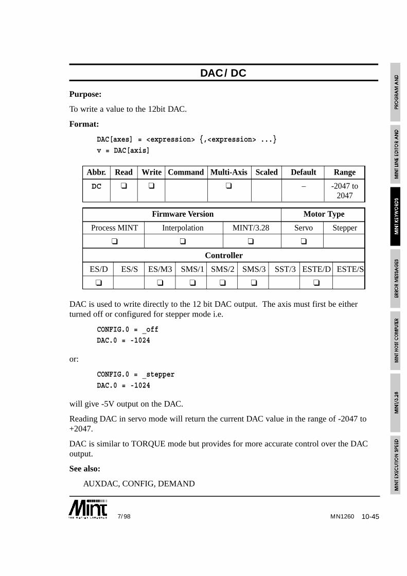
10-457/98 MN1260
DAC/DC
Purpose:
To write a value to the 12bit DAC.
Format:
DAC[axes] = <expression> {,<expression> ...}
v = DAC[axis]
Abbr. Read Write Command Multi-Axis Scaled Default Range
DC ❑ ❑ ❑ – -2047 to2047
Firmware Version Motor Type
Process MINT Interpolation MINT/3.28 Servo Stepper
❑ ❑ ❑ ❑
Controller
ES/D ES/S ES/M3 SMS/1 SMS/2 SMS/3 SST/3 ESTE/D ESTE/S
❑ ❑ ❑ ❑ ❑ ❑
DAC is used to write directly to the 12 bit DAC output. The axis must first be eitherturned off or configured for stepper mode i.e.
CONFIG.0 = _offDAC.0 = -1024
or:
CONFIG.0 = _stepper
DAC.0 = -1024
will give -5V output on the DAC.
Reading DAC in servo mode will return the current DAC value in the range of -2047 to+2047.
DAC is similar to TORQUE mode but provides for more accurate control over the DACoutput.
See also:
AUXDAC, CONFIG, DEMAND

10-46 7/98MN1260
DATATIME/DT
Purpose:
To specify the time over which data capture occurs
Format:
DATATIME = <expr>
v = DATATIME
Abbr. Read Write Command Multi-Axis Scaled Default Range
DT ❑ ❑ – 0 to 32000
Firmware Version Motor Type
Process MINT Interpolation MINT/3.28 Servo Stepper
❑ ❑ ❑
Controller
ES/D ES/S ES/M3 SMS/1 SMS/2 SMS/3 SMM/1 SMM/2 SMM/3 SST/3 ESTE/D ESTE/S
❑ ❑ ❑ ❑ ❑ ❑ ❑ ❑
DATATIME specifies the time in milli-seconds over which data capture will occur.DATATIME should be called prior to the first call to CAPTURE.
Reading DATATIME will return the remaining capture time.
Data capture is discussed in detail in section 7.5.
See also:
AUX, CAPTURE
DECEL/DE
Purpose:
To set a deceleration rate on the axis.
Format:
DECEL[axes] = <expr> {,<expr> ...}
v = DECEL[axis]

10-477/98 MN1260
Abbr. Read Write Command Multi-Axis Scaled Default Range
DE ❑ ❑ ❑ ❑ 300,000 1000.0 to8388607.0
Firmware Version Motor Type
Process MINT Interpolation MINT/3.28 Servo Stepper
❑ ❑ ❑ ❑ ❑
Controller
ES/D ES/S ES/M3 SMS/1 SMS/2 SMS/3 SMM/1 SMM/2 SMM/3 SST/3 ESTE/D ESTE/S
❑ ❑ ❑ ❑ ❑ ❑ ❑ ❑ ❑ ❑ ❑ ❑
The DECEL keyword allows a deceleration value to be imposed on the axis. This appliesto the move types: CIRCLEA, CIRCLER, JOG, MOVEA, MOVER, OFFSET, PULSE,VECTORA, VECTORR.
In order to allow backwards compatibility, DECEL must be switched on using the newAXISCON keyword. If it is switched off, DECEL can be used, but any write to ACCELwill overwrite the DECEL value with ACCEL.
DECEL like ACCEL is expressed in counts/second2. Unlike ACCEL, there is nocorresponding DECELTIME keyword.
Note: Due to the resolution and representation of numbers in MINT it is notalways possible to store the exact value of DECEL. When writing to DECEL,
the value is converted from units per second to counts per servo loop.This can lead to rounding errors.
Example:
AXISCON.0 = AXISCON.0 | 01 : REM Turn off DECEL termACCEL = 1000
DECEL = 2000
Note the use of a binary number and bitwise OR to retain bit settings on AXISCON.
On a stop input becoming active, the axes will decelerate at the DECEL rate.
DECEL can be changed at any time during a move. MINT will change the decelerationvalue on the fly if necessary, in order to stop at the correct end.
See also:
ACCEL, ACCELTIME, AXISCON, JOG, MOVEA, MOVER, OFFSET, PULSE,STOP, VECTORA, VECTORR

10-48 7/98MN1260
DEFAULT/DF
Format:
DEFAULT[axes]
Abbr. Read Write Command Multi-Axis Scaled Default Range
DF ❑ ❑ – –
Firmware Version Motor Type
Process MINT Interpolation MINT/3.28 Servo Stepper
❑ ❑ ❑ ❑ ❑
Controller
ES/D ES/S ES/M3 SMS/1 SMS/2 SMS/3 SST/3 ESTE/D ESTE/S
❑ ❑ ❑ ❑ ❑ ❑ ❑ ❑ ❑
Returns all motion variables to their power-up values. This is equivalent to switching thecontroller off and then on again. It allows you to start afresh in commissioning shouldthings go very wrong. Note that DEFAULT is different to RESET in that RESET does notreset the following parameters:
ACCEL, BACKOFF, CONFIG, CURRLIMIT, ERRORIN, FOLLOWAXIS, GAIN,HMSPEED, KINT, KINTRANGE, KVEL, KVELFF, LOOPTIME, MFOLERR, RAMP,SCALE, SPEED, WRAP
Example:
DEFAULT[0]
set axis zero parameters to their power-up values.
See also:
CANCEL, RESET

10-497/98 MN1260
DEMAND/DM
Purpose:
To read back the instantaneous motor demand.
Format:
v = DEMAND[axis]
Abbr. Read Write Command Multi-Axis Scaled Default Range
DM ❑ ❑ – -100 to 100%
Firmware Version Motor Type
Process MINT Interpolation MINT/3.28 Servo Stepper
❑ ❑ ❑ ❑
Controller
ES/D ES/S ES/M3 SMS/1 SMS/2 SMS/3 SST/3 ESTE/D ESTE/S
❑ ❑ ❑ ❑ ❑ ❑
Return instantaneous motor demand. This returns a value in the range -100 to +100 whichrepresents the percentage of the amplifier peak current or voltage capability. The DACkeyword can be used to read the actual 12 bit value written to the DAC.
Example:
TORQUE = 50
? DEMAND
will print 50 to the terminal.
See also:
CURRLIMIT, DAC, TORQUE
DIM
Purpose:
To reserve memory for array variables.
Format:
DIM {OFFLINE} array_name(<no_of_elements>) { = <array values> }
where <no_of_elements> and <array values> are MINT numbers and not expressions.

10-50 7/98MN1260
Reserves data space for array variables and optionally initializes them. Example:
DIM my_array(100)
declares an array variable called my_array with one hundred elements.
DIM y_position(10) = 1,2,3,4,5,6,7,8,9,10
declares an array y_position, where the first element, y_position(1), is equal to 1, secondequal to 2 etc.
The array variable name can also be used as a normal variable. For example:
y_position = 1
will treat y_position as a standard variable.
Data can also be reserved to reside on a memory card using the OFFLINE keyword. Forexample:
DIM OFFLINE myData(100)
See section 4.5 on array data for more detail on the use of DIM.
Notes:
DIM cannot be used on the command line.
The COMMSON keyword, used to enable protected protocol mode, will automaticallycreate a 99 element array with the variable name comms. COMMSON must be placedbefore any DIM statements.
Expressions or variables cannot be used in the array declaration. The following willall result in an error:
DIM myData(x)
DIM myData2( 3 ) = a,a+1,b+2
Character constants can be used in an array declaration:
DIM funcKey(6) = ‘A’, ‘B’, ‘C’, ‘D’, ‘E’, ‘F’
See also:
COMMSON, DISPLAY, FREE, LOAD, OFFLINE, RELEASE, SAVE

10-517/98 MN1260
DINTPurpose:To disable MINT interruptsFormat:
DINTThe DINT command will disable MINT interrupts #IN0 to #IN7 and the fast positioninterrupt (#FASTPOS). To ensure all subsequent interrupts are disabled when an interruptroutine is called, the DINT command must be placed on the next line following the label.For example:
#IN0DINT...
RETURN
The EINT command will re-enable MINT interrupts.
IMASK can be used to selectively enable MINT interrupts. If, for example, you which todisable interrupts #IN0 to #IN3, the following command sequence would be used:
DINT : REM Disable interruptsIMASK = 011110000EINT : REM re-enable interrupts
See also:#FASTPOS, #IN0..#IN7, EINT, IMASK, IPEND
DIR/DRPurpose:To define the active state of the direction output for inverter control
Format:DIR = 0 or 1
Abbr. Read Write Command Multi-Axis Scaled Default RangeDR ❑ ❑ ❑ 0 to 1
Firmware Version Motor TypeProcess MINT Interpolation MINT/3.28 Servo Stepper
❑ ❑ ❑ ❑
ControllerES/D ES/S ES/M3 SMS/1 SMS/2 SMS/3 SST/3 ESTE/D ESTE/S
❑ ❑ ❑ ❑ ❑ ❑
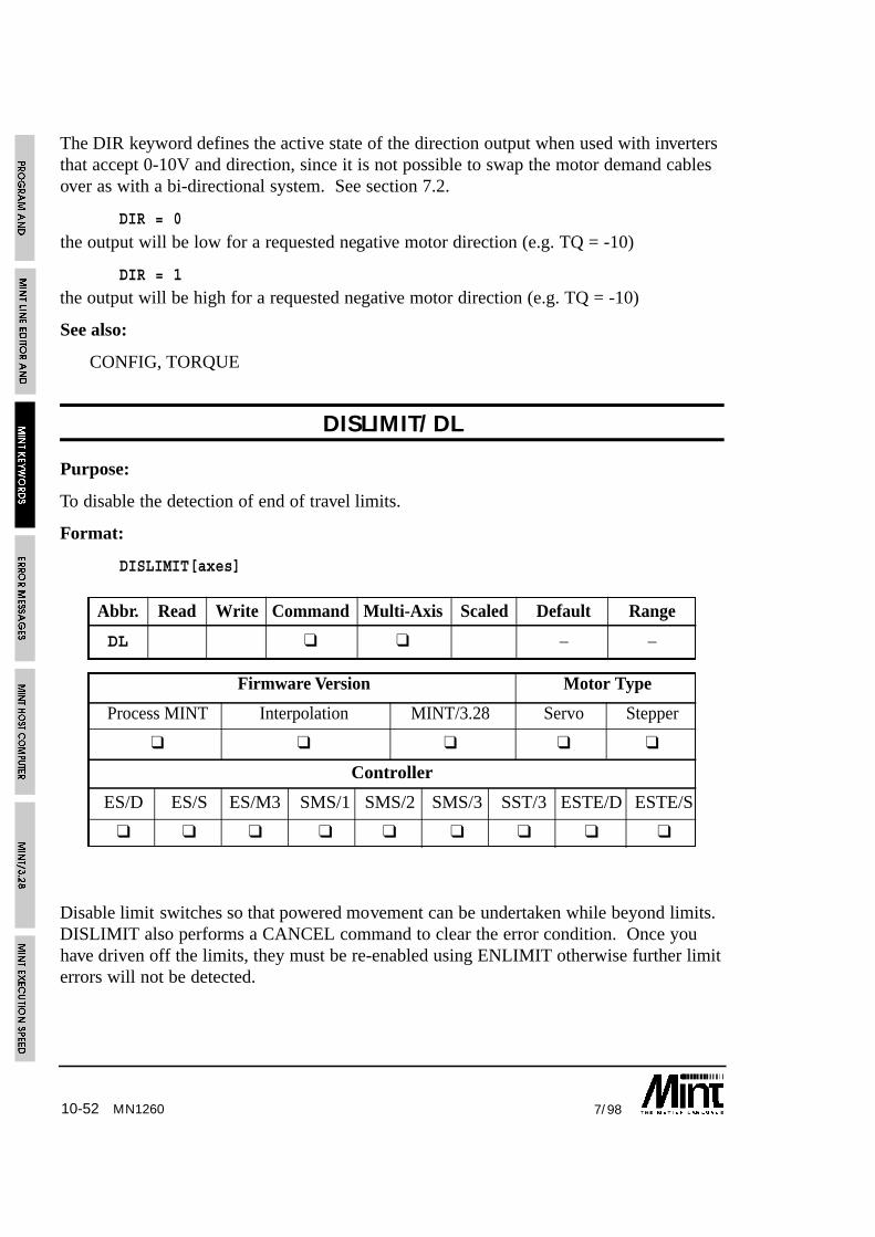
10-52 7/98MN1260
The DIR keyword defines the active state of the direction output when used with invertersthat accept 0-10V and direction, since it is not possible to swap the motor demand cablesover as with a bi-directional system. See section 7.2.
DIR = 0
the output will be low for a requested negative motor direction (e.g. TQ = -10)
DIR = 1the output will be high for a requested negative motor direction (e.g. TQ = -10)
See also:
CONFIG, TORQUE
DISLIMIT/DL
Purpose:
To disable the detection of end of travel limits.
Format:
DISLIMIT[axes]
Abbr. Read Write Command Multi-Axis Scaled Default Range
DL ❑ ❑ – –
Firmware Version Motor Type
Process MINT Interpolation MINT/3.28 Servo Stepper
❑ ❑ ❑ ❑ ❑
Controller
ES/D ES/S ES/M3 SMS/1 SMS/2 SMS/3 SST/3 ESTE/D ESTE/S
❑ ❑ ❑ ❑ ❑ ❑ ❑ ❑ ❑
Disable limit switches so that powered movement can be undertaken while beyond limits.DISLIMIT also performs a CANCEL command to clear the error condition. Once youhave driven off the limits, they must be re-enabled using ENLIMIT otherwise further limiterrors will not be detected.

10-537/98 MN1260
Example:
#ONERROR
DISLIMIT[0,1] : REM Disable limitsSERVOFF[0,1] : REM Allow manual movement of axis
PAUSE !LIMIT[0,1] : REM Wait to move off limits
SERVOC[0,1] : REM Servo power on
ENLIMIT[0,1] : REM Re-enable the limits
RETURN : REM and resume execution
If limits are not used they should ideally be tied to ground rather than relying on theDISLIMIT keyword.
DISLIMIT will also turn contouring off, and reset GEARN and GEARD to 0 and 1respectively.
Issuing a RESET command will re-enable the limits.
See also:
ENLIMIT, LIMIT
DISPLAY
Purpose:
To display all currently defined variables and array data.
Format:
DISPLAY
DISPLAY will show all the currently defined variables and their values followed by all thearray data.
See also:
RELEASE
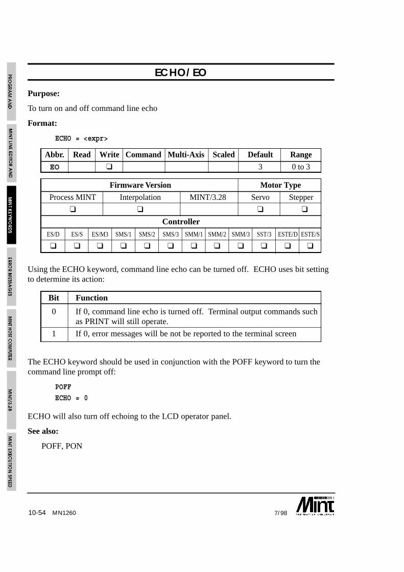
10-54 7/98MN1260
ECHO/EO
Purpose:
To turn on and off command line echo
Format:
ECHO = <expr>
Abbr. Read Write Command Multi-Axis Scaled Default Range
EO ❑ 3 0 to 3
Firmware Version Motor Type
Process MINT Interpolation MINT/3.28 Servo Stepper
❑ ❑ ❑ ❑
Controller
ES/D ES/S ES/M3 SMS/1 SMS/2 SMS/3 SMM/1 SMM/2 SMM/3 SST/3 ESTE/D ESTE/S
❑ ❑ ❑ ❑ ❑ ❑ ❑ ❑ ❑ ❑ ❑ ❑
Using the ECHO keyword, command line echo can be turned off. ECHO uses bit settingto determine its action:
Bit Function
0 If 0, command line echo is turned off. Terminal output commands suchas PRINT will still operate.
1 If 0, error messages will be not be reported to the terminal screen
The ECHO keyword should be used in conjunction with the POFF keyword to turn thecommand line prompt off:
POFF
ECHO = 0
ECHO will also turn off echoing to the LCD operator panel.
See also:
POFF, PON
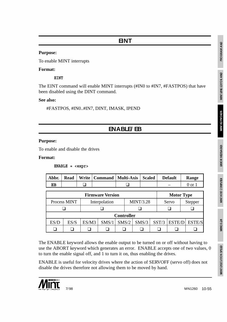
10-557/98 MN1260
EINT
Purpose:
To enable MINT interrupts
Format:
EINT
The EINT command will enable MINT interrupts (#IN0 to #IN7, #FASTPOS) that havebeen disabled using the DINT command.
See also:
#FASTPOS, #IN0..#IN7, DINT, IMASK, IPEND
ENABLE/EB
Purpose:
To enable and disable the drives
Format:
ENABLE = <expr>
Abbr. Read Write Command Multi-Axis Scaled Default Range
EB ❑ ❑ – 0 or 1
Firmware Version Motor Type
Process MINT Interpolation MINT/3.28 Servo Stepper
❑ ❑ ❑ ❑ ❑
Controller
ES/D ES/S ES/M3 SMS/1 SMS/2 SMS/3 SST/3 ESTE/D ESTE/S
❑ ❑ ❑ ❑ ❑ ❑ ❑ ❑ ❑
The ENABLE keyword allows the enable output to be turned on or off without having touse the ABORT keyword which generates an error. ENABLE accepts one of two values, 0to turn the enable signal off, and 1 to turn it on, thus enabling the drives.
ENABLE is useful for velocity drives where the action of SERVOFF (servo off) does notdisable the drives therefore not allowing them to be moved by hand.

10-56 7/98MN1260
Example:
SERVOFF : REM Turn the servos off
ENABLE = _off : REM Disable the drivesPAUSE INKEY : REM Move motors until a key is pressed
SERVOC : REM Turn the servos on
ENABLE = _on : REM Enable the drives
This example will turn the servos off, so as not to generate a following error, and disableall the drives. The motors can now be moved freely by hand until a key is pressed on theterminal. The servos will then be turned on at their current position and the drivesenabled.
See also:
#ONERROR, ABORT, SERVOC, SERVOFF, SERVON
ENCODER/EN
Purpose:
To read back the encoder position when an axis is either in stepper mode or is switchedoff.
Format:
ENCODER[axes] = <expr> {,<expr> ...}
v = ENCODER[axis]
Abbr. Read Write Command Multi-Axis Scaled Default Range
EN ❑ ❑ ❑ – -8388607 to8388607
Firmware Version Motor Type
Process MINT Interpolation MINT/3.28 Servo Stepper
❑ ❑ ❑ ❑
Controller
ES/D ES/S ES/M3 SMS/1 SMS/2 SMS/3 SST/3 ESTE/D ESTE/S
❑ ❑ ❑ ❑ ❑ ❑

10-577/98
Returns the encoder position. This will allow for a form of closed loop on a steppermotor. If we assume that we have the same number of quad count to steps on the steppermotor, the following subroutine, correction, can be used to correct for any missing steps:
SF = 1
MA = 1000 : GOPAUSE IDLE
GOSUB correction
END
#correctionREM Read the position we should be at
finalPos = POS[0]
REM Keep correcting until we get to the position
WHILE ENCODER.0 <> finalPosMR.0 = finalPos - ENCODER.0 : GO.0
PAUSE POS.0 = MOVEA.0:REM Wait till pulse chain complete
WAIT = 20 :REM Wait till motor has stopped oscillating
:REM This value can be ‘tuned’ENDW
REM Reset the position to the actual encoder position
POS.0 = ENCODER.0
RETURN
Notes:
• ENCODER is not scaled by the SCALE keyword and must be scaled in software.
• The encoder position can be set by writing to the ENCODER keyword.
• Writing to ENCODER has no effect on POS and vice versa
• The ENCODER value is latched to FASTENC on a fast interrupt.
The ENCWRAP keyword can be used to restrict the ENCODER value in the range of 0 to(ENCWRAP-1). This is useful in rotary systems to determine the position of the motor inone revolution. For example, a encoder has 4000 counts per revolution
ENCWRAP = 4000will return an encoder value in the range of 0 to 3999.
See also:
#FASTPOS, ENCWRAP, FASTENC, POS
MN1260

10-58 7/98MN1260
ENCWRAP/EW
Purpose:
To restrict the ENCODER value in the range of 0 to (ENCWRAP-1)
Format:
ENCWRAP[axes] = <expr> {,<expr> ... }
Abbr. Read Write Command Multi-Axis Scaled Default Range
EW ❑ ❑ 0 0 to 65535
Firmware Version Motor Type
Process MINT Interpolation MINT/3.28 Servo Stepper
❑ ❑ ❑ ❑
Controller
ES/D ES/S ES/M3 SMS/1 SMS/2 SMS/3 SST/3 ESTE/D ESTE/S
❑ ❑ ❑ ❑ ❑ ❑
The ENCWRAP keyword is used to restrict the ENCODER value in the range of 0 to(ENCWRAP-1). This is useful in rotary systems to determine the position of the motor inone revolution. For example, a encoder has 4000 counts per revolution
ENCWRAP = 4000
will return an encoder value in the range of 0 to 3999.
ENCWRAP is equivalent to :
ENCODER = ENCODER % ENCWRAP
A value of 0 will disable the ENCWRAP keyword allowing the full range value for theENCODER keyword. ENCWRAP will only affect the ENCODER keyword and not thePOS keyword.
See also:
ENCODER, FASTENC

10-597/98 MN1260
END
Purpose:
To terminate program execution.
Format:
END
Ends program execution and returns the user to the prompt. If END is placed in aconfiguration file, the program file is executed.
ENLIMIT/EL
Purpose:
To enable the detection of end of travel limits.
Format:
ENLIMIT[axis]
Abbr. Read Write Command Multi-Axis Scaled Default Range
EL ❑ ❑ – –
Firmware Version Motor Type
Process MINT Interpolation MINT/3.28 Servo Stepper
❑ ❑ ❑ ❑ ❑
Controller
ES/D ES/S ES/M3 SMS/1 SMS/2 SMS/3 SST/3 ESTE/D ESTE/S
❑ ❑ ❑ ❑ ❑ ❑ ❑ ❑ ❑
Enable the detection of the limit switches after a DISLIMIT command. This is the defaulton power up or when RESET is issued.
10-60 7/98
Example:
#ONERROR
DISLIMIT[0,1] : REM Disable limitsSERVOFF[0,1] : REM Allow manual movement of axis
PAUSE !LIMIT[0,1] : REM Wait to move off limits
SERVOC[0,1] : REM Servo power on
ENLIMIT[0,1] : REM Re-enable the limits
RETURN : REM and resume execution
ENLIMIT is different from DISLIMIT in that it does not force a CANCEL.
See also:
DISLIMIT, LIMIT, RESET
ERR
Purpose:
To read the MINT error which resulted in the calling of ONERROR.
Format:
v = ERR
When ONERROR is called, ERR is set with an error number. This can be used in theONERROR routine to determine the error. ERR should be used on conjunction withERROR to determine the axis error.
Error handling is explained in more detail in section 8.
See Also:
ERROR, ERRAXIS
MN1260

10-617/98 MN1260
ERRAXIS
Purpose:
To read the number of the axis which resulted in the calling of ONERROR.
Format:
v = ERRAXIS
When ONERROR is called, ERRAXIS is set with the number of the axis which resultedin the error. This can be used in the ONERROR routine to determine the error. ERRshould be used on conjunction with ERR to determine the axis error.
Error handling is explained in more detail in section 8.
See Also:
ERROR, ERR
ERROR/ER
Purpose:
To read back the motion error.
Format:
v = ERROR[axis]
Abbr. Read Write Command Multi-Axis Scaled Default Range
ER ❑ ❑ – 0 to 11
Firmware Version Motor Type
Process MINT Interpolation MINT/3.28 Servo Stepper
❑ ❑ ❑ ❑ ❑
Controller
ES/D ES/S ES/M3 SMS/1 SMS/2 SMS/3 SST/3 ESTE/D ESTE/S
❑ ❑ ❑ ❑ ❑ ❑ ❑ ❑ ❑

10-62 7/98MN1260
A read only motion variable that is used to identify axis error conditions as follows:
Code Constant Status LED Meaning
0 No error condition (see MODE).
1 _abort E Software abort.
2 _maxfe F Max following error exceeded.
3 _limit L Limit switch closed.
11 _external Ø External (error input) error.
13 ß Digital output error (SmartMove)
The only way to recover from an error without disconnecting power is to issue theRESET, DISLIMIT or CANCEL commands. Unless there is an error handling routinepresent (see ONERROR), the interpreter will terminate and issue an error message via theserial port.
Example:
#ONERROR
IF ERROR.0 = _limit DO : REM Limit errorDISLIMIT.0 : REM Disable the limits
SERVOFF.0 : REM Disable amplifiers
PAUSE !LIMIT.0 : REM Manually move off limits
SERVOC.0 : REM Restore power to motorsENLIMIT.0 : REM Enable limits
ENDIF
RETURN
MINT/3.28 extends the values returned by ERROR should a datapacket be rejected. Seesection 13.3.1 for more details.
See also:
ABORT, CANCEL, ENABLE, ERRORIN, FOLERR, LED, LIMIT, MFOLERR,#ONERROR, RESET

10-637/98 MN1260
ERRORIN/EI
Purpose:
To set the active state of the external error input or read the current state of the input.
Format:
ERRORIN = <expr>
Abbr. Read Write Command Multi-Axis Scaled Default Range
EI ❑ ❑ 2 0 to 2
Firmware Version Motor Type
Process MINT Interpolation MINT/3.28 Servo Stepper
❑ ❑ ❑ ❑ ❑
Controller
ES/D ES/S ES/M3 SMS/1 SMS/2 SMS/3 SST/3 ESTE/D ESTE/S
❑ ❑ ❑ ❑ ❑ ❑ ❑ ❑ ❑
Determines the state of the error input (external error). ERRORIN accepts one of thefollowing values:
Value Function
0 Error input active low.
1 Error input active high
2 Error input disabled
ERRORIN will default to 2 on power up and should be changed to suit your system.
Example:
ERRORIN = 0will set the error input to active low. If an ONERROR subroutine is defined, this will becalled when the error input is grounded (connect to power if PNP inputs are used).
Reading ERRORIN will return the state of the error input.
See also:
ERROR, #ONERROR

10-64 7/98
EXIT
Purpose:
To terminate the current loop or block structure.
Format:
EXIT
Forces termination of a loop. EXIT can be used to leave any of the following loopconstructs:
FOR .. NEXTLOOP .. ENDL
REPEAT .. UNTIL
WHILE .. ENDW
Program execution commences on the line following the terminating statement in the loop.EXIT is useful for terminating loops when a condition becomes true:
LOOP{statements}
IF IN1 = 1 THEN EXIT
{statements}
ENDL
? “End Loop”
if input 1 goes active, “End Loop” will be printed to the terminal.
See also:
FOR .. NEXT, LOOP..ENDL, REPEAT..UNTIL, WHILE..ENDW
FASTENC/FC
Purpose:
To return the instantaneous ENCODER position recorded by a fast interrupt
Format:
v = FASTENC[axis]
MN1260
10-657/98 MN1260
Abbr. Read Write Command Multi-Axis Scaled Default Range
FC ❑ ❑ – –
Firmware Version Motor Type
Process MINT Interpolation MINT/3.28 Servo Stepper
❑ ❑ ❑ ❑
Controller
ES/D ES/S ES/M3 SMS/1 SMS/2 SMS/3 SMM/1 SMM/2 SMM/3 SST/3 ESTE/D ESTE/S
❑ ❑ ❑ ❑ ❑ ❑ ❑ ❑ ❑
The ENCODER position is latched to the FASTENC keyword on the fast interrupt. Thisoperates in the same way as FASTPOS. If an ENCWRAP value is defined, the FASTENCvalue will be returned within the range of 0 to (ENCWRAP - 1).
Example:
#FASTPOS
IF MODE = _follow THEN OFFSET = FASTENC - 1000
RETURN
See also:
#FASTPOS, ENCODER, ENCWRAP, FASTPOS
FASTPOS/FP
Purpose:
To return the instantaneous position that was recorded on the fast interrupt.
Format:
v = FASTPOS[axis]
Abbr. Read Write Command Multi-Axis Scaled Default Range
FP ❑ ❑ ❑ – –
Firmware Version Motor Type
Process MINT Interpolation MINT/3.28 Servo Stepper
❑ ❑ ❑ ❑ ❑
Controller
ES/D ES/S ES/M3 SMS/1 SMS/2 SMS/3 SST/3 ESTE/D ESTE/S
❑ ❑ ❑ ❑ ❑ ❑ ❑ ❑ ❑

10-66 7/98
When the controller receives a fast interrupt, the axis position is read and stored in theFASTPOS keyword. Unlike the POS keyword which is updated every loop closure (1 or 2milli-seconds), the FASTPOS position is the axis position read at the time of the fastinterrupt. The maximum latency to read the fast position is in the order of 30 micro-seconds.
If the #FASTPOS subroutine is defined, this will be called in response to the fast interrupt.Unlike the MINT interrupts which require a minimum pulse width of 2ms, the fastinterrupt will be latched on a pulse width of about 30 micro-seconds, although a width of100 micro-seconds is recommended. The fast interrupt is level dependent, the positionbeing latched when the fast interrupt is high.
Due to the speed of the fast interrupt, it may be necessary to de-couple the input to avoidspurious calls to the #FASTPOS routine.
The value returned by the FASTPOS keyword is dependent on the scale factor.
Example:
#FASTPOSREM Measure distance between 2 consecutive fast interrupts
IF FASTPOS.1 - lastFastPos > labelLength/2 DO
measured = FASTPOS.1 - lastFastPos
lastFastPos = FASTPOS.1ENDIF
RETURN
In a mixed servo/stepper system, only the servo axes will be latched by the fast interrupt.
See also:
#FASTPOS, ENCODER, FASTENC, POS
FLY/FY
Purpose:
To create a flying shear by locking the slave position to master position with controlledacceleration and deceleration.
Format:
FLY[axes] = <expr> {,<expr>}
MN1260

10-677/98 MN1260
17Axes 0 and 1 only
Abbr. Read Write Command Multi-Axis Scaled Default Range
FY ❑ ❑17 ❑ – -32767 to32767
Firmware Version Motor Type
Process MINT Interpolation MINT/3.28 Servo Stepper
❑ ❑
Controller
ES/D ES/S ES/M3 SMS/1 SMS/2 SMS/3 SST/3 ESTE/D ESTE/S
❑ ❑ ❑ ❑ ❑ ❑
Sets the incremental distance in user units to be moved as a result of the measuredmovement (MASTERINC) on the master axis.
If a move is required that is longer than the valid range, moves must be split up.
Example:
Assuming the slave axis is running at a 1:1 ratio with the master, a slave move of 40000 isrequired over a measured master distance of 40000:
MI = 20000FY = 20000 : GO
MI = 20000
FY = 20000 : GO
When performing a FLY operation, the status display will show an F (with no flashingdot) and the MODE keyword will return 15.
Assigning a value of 0 to FLY will cause the slave to wait the measured distance on themaster.
Notes:
• Flying shears are only supported on axes 0 and 1.
• It is assumed that the master is moving uni-directionally.
• The slave, given a positive, FLY will always move in a positive direction regardless ofthe direction of the master.
• From esMINT v2.71, an OFFSET can be performed on a FLY. Previous, a “motion inprogress” error would result.
10-68 7/98MN1260
• FLY moves are buffered in the same was as position moves. To set an output, forexample, when the slave has reached its desired position, the OUT statement must beplaced after the buffered move as shown:
MI = 1000
FY = 500 : GOFY = 1000 : GO
OUT0 = 1 : REM Set output when FY = 500 has finished
See section 6.8 for details on flying shears.
See also:
CAM. CAMA, FOLLOW, FOLLOWAXIS, GEARN, GEARD, GO, MASTERINC,TRIGGER
FOLERR/FE
Purpose:
To return the instantaneous following error value.
Format:
v = FOLERR[axis]
Abbr. Read Write Command Multi-Axis Scaled Default Range
FE ❑ ❑ ❑ – -32767 to32767
Firmware Version Motor Type
Process MINT Interpolation MINT/3.28 Servo Stepper
❑ ❑ ❑ ❑ ❑
Controller
ES/D ES/S ES/M3 SMS/1 SMS/2 SMS/3 SST/3 ESTE/D ESTE/S
❑ ❑ ❑ ❑ ❑ ❑
10-697/98
Returns instantaneous following error where the following error is defined as the demandposition (where you want to be) minus the actual motor position. If the following errorexceeds the value set by MFOLERR (maximum following error) an error is generatedwhich is shown by an ‘F’ on the LCD display and the ERROR keyword will be set to 2. Ifan ONERROR routine is defined, this will be called otherwise program execution will beaborted with the error message:
ERROR: Program: Following error on axis Y at line XXX
Reading the following error during a move is useful for tuning the system. For example:
MOVEA = 100 : GO.0
WHILE !IDLE.0? FE.0
ENDW
? FE.0
will print the following error continuously to the terminal while the move is in progress.
Note that the value returned is dependent on the scale factor, SCALE. For systemcommissioning, the following error can be written to a DAC output using the AUXkeyword. This allows you to view the following error using an oscilloscope.
Velocity feedforward (KVELFF) can be used to reduce the dynamic following error.KINT can be used to reduce the static following error.
See also:
AUX, ERROR, MFOLERR, POS, SCALE
FOLLOW/FL
Purpose:
To enable encoder following with a specified gear ratio.
Format:
FOLLOW[axes] = <expression> {,<expression> ...}
v = FOLLOW[axis]
MN1260

10-70 7/98MN1260
Abbr. Read Write Command Multi-Axis Scaled Default Range
FL ❑ ❑ ❑ 0 -127.996 to127.996
Firmware Version Motor Type
Process MINT Interpolation MINT/3.28 Servo Stepper
❑ ❑ ❑ ❑ ❑
Controller
ES/D ES/S ES/M3 SMS/1 SMS/2 SMS/3 SST/3 ESTE/D ESTE/S
❑ ❑ ❑ ❑ ❑ ❑ ❑ ❑ ❑
The FOLLOW keyword will allow one encoder to follow another encoder on the samecontroller. The expression defines the gear ratio and the direction between the two axes.The led will show a backwards ‘F’ when in FOLLOW mode.
FOLLOW is stopped by either:
FOLLOW.0 = 0
or:
STOP.0
FOLLOW does not ramp up to speed using the defined acceleration. Therefore if youexecute FOLLOW on an axis which is already in motion, the axis will accelerateinstantaneously to the speed of the following motor.
During encoder following, an offset can be applied to the base speed using the OFFSETkeyword. See OFFSET for more details.
The FOLLOWAXIS is used to configure the axis to follow.
Reading FOLLOW will return the last value assigned to it. See section 6.6 for moredetails on encoder following.
Note that the move can be triggered to start on an inputusing the TRIGGER keyword.
See also:
CAM, CAMA, FLY, FOLLOWAXIS, FOLLOWAXIS, GEARN, GEARD, MODE,OFFSET, PULSE, TRIGGER
10-717/98 MN1260
FOLLOWAXIS/FA
Purpose:
To set which axis to follow under FOLLOW mode.
Format:
FOLLOWAXIS[axes] = <axis> {,<axis> ... }
Abbr. Read Write Command Multi-Axis Scaled Default Range
FA ❑ ❑ ❑ 0 -2 to 5
Firmware Version Motor Type
Process MINT Interpolation MINT/3.28 Servo Stepper
❑ ❑ ❑ ❑ ❑
Controller
ES/D ES/S ES/M3 SMS/1 SMS/2 SMS/3 SST/3 ESTE/D ESTE/S
❑ ❑ ❑ ❑ ❑ ❑ ❑ ❑ ❑
FOLLOWAXIS is used in conjunction with the FOLLOW keyword to set the axis tofollow. For example:
FOLLOWAXIS[0] = 2
FOLLOW[0] = 1
Set axis 0 to follow axis 2 with a gear ratio of 1:1.
FOLLOWAXIS = 2,2FOLLOW = 1,2.5
Axes 0 and 1 follow axis 2 (assuming AXES[0,1]) with a gear ratio of 1:1 and 2.5:1respectively.
10-72 7/98MN1260
By default, axis 0 will follow axis 1 and axis 1 will follow axis 0. FOLLOWAXIS acceptsany of the following values:
Value Function
-2 Following the pulse timer input.
-1 Follow a constant base speed as set by SPEED.
0 Follow axis 0
1 Follow axis 1
2 Follow axis 2
3 Follow external encoder channel 0. Applicable only if theexternal encoder interface is fitted (and with firmware option).
4 Follow external encoder channel 1. Applicable only if theexternal encoder interface is fitted (and with firmware option).
5 Follow external encoder channel 2. Applicable only if theexternal encoder interface is fitted (and with firmware option).
See also:
CAM, CAMA, FLY, FOLLOW, PULSE, XENCODER
FOR .. NEXT
Purpose:
To execute a series of instructions a specified number of times in a loop.
Format:
FOR <variable> = <expr1> TO <expr2> {STEP <expr3>}
{statements}
NEXT
The FOR loop is the BASIC implementation of the FOR loop allowing for incrementingand decrementing of the <variable> as defined by the STEP size, <expr3>. <expr1> ,<expr2> and <expr3> can be any valid expressions. FOR loops are terminated with aNEXT statement. There must be no variable name after the NEXT statement as withstandard forms of BASIC.

10-737/98
Example:
FOR a = 1 TO 10 : REM Perform loop 10 times
REM Move to the XY position in the arrayMOVEA = xpos(a), ypos(a) : GO
PAUSE IDLE[0,1] : REM Wait for axes to stop
OUT1 = _on : REM Set the output
WAIT = 250 : REM Wait 1/4 second
OUT = _off : REM Turn the output offNEXT
When the loop terminates, the value of the variable will equal the upper limit (expr2). Itwill never exceed it for a positive number.
FOR .. NEXT loops may be nested up to 10 levels as follows:
FOR a = 1 TO 100 STEP 10MOVEA[0] = a : GO
FOR b = 1 to 10
MOVEA[1] = b : GO
NEXTNEXT
A FOR NEXT loop can be terminated prematurely using the EXIT keyword.
See also:
EXIT, LOOP..ENDL, REPEAT..UNTIL, WHILE..ENDW
FREQ/FQ
Purpose:
To set a constant frequency output.
Format:
FREQ[axes] = <expression> {,<expression> ...}v = FREQ[axis]
MN1260
10-74 7/98MN1260
Abbr. Read Write Command Multi-Axis Scaled Default Range
FQ ❑ ❑ ❑ – 124 to8000000
Firmware Version Motor Type
Process MINT Interpolation MINT/3.28 Servo Stepper
❑ ❑ ❑ ❑
Controller
ES/D ES/S ES/M3 SMS/1 SMS/2 SMS/3 SST/3 ESTE/D ESTE/S
❑ ❑ ❑ ❑ ❑
Allow user to set frequency output in the range of 124Hz to 8Mhz. The axis must be inservo mode or turned off. i.e.
CONFIG[0] = _off
FREQ[0] = 1000
will give a 1000Hz frequency output on stepper axis 0.
See also:
CONFIG, DAC
GAIN/GN
Purpose:
To set the servo loop proportional gain.
Format:
GAIN[axes] = <expression> {,<expression> ...}v = GAIN[axis]
Abbr. Read Write Command Multi-Axis Scaled Default Range
GN ❑ ❑ ❑ 0 0 to 255.0
Firmware Version Motor Type
Process MINT Interpolation MINT/3.28 Servo Stepper
❑ ❑ ❑ ❑
Controller
ES/D ES/S ES/M3 SMS/1 SMS/2 SMS/3 SST/3 ESTE/D ESTE/S
❑ ❑ ❑ ❑ ❑ ❑

10-757/98 MN1260
18Axes 0 and 1 only
Sets the digital servo loop proportional gain. See the Getting Started Guide for details onsetting this parameter.
Example:
GAIN = 1.5,2.5
DEFAULT can be used to set all servo loop gains to zero.
The effects of the servo loop parameters can be monitored using the AUX keyword and anoscilloscope. Alternatively, cTERM for Windows can be used for system tuning.
See also:
AUX, CURRLIMIT, DAC, DEFAULT, DEMAND, KINT, KINTRANGE, KVEL,KVELFF, TORQUE
GEARD/GD
Purpose:
To define a denominator value for high resolution position following.
Format:
GEARD[axes] = <expr> {,<expr>}
v = GEARD[axis]
Abbr. Read Write Command Multi-Axis Scaled Default Range
GD ❑ ❑ ❑18 1 1 to 32000
Firmware Version Motor Type
Process MINT Interpolation MINT/3.28 Servo Stepper
❑ ❑ ❑
Controller
ES/D ES/S ES/M3 SMS/1 SMS/2 SMS/3 SST/3 ESTE/D ESTE/S
❑ ❑ ❑ ❑ ❑ ❑
To overcome the limitations of MINT scaled integers, a gear ratio for position followingcan be defined in terms of a numerator and denominator such that the ratio is defined as:
gear ratio = GEARN/GEARD
GEARD defines the denominator term.

10-76 7/98MN1260
19Axes 0 and 1 only
GEARD must be defined before GEARN can be used otherwise a Motion in Progresserror will result.
Note: Before an OFFSET move can be performed, it is important to ensurethat the initial fly acceleration ramp has completed. This restriction does not
apply from esMINT v2.71.
See also:
GEARN, FOLLOWAXIS, FOLLOW, PULSE
GEARN/GR
Purpose:
To define a numerator value for high resolution position following.
Format:
GEARN[axes] = <expr> {,<expr>}v = GEARN[axis]
Abbr. Read Write Command Multi-Axis Scaled Default Range
GR ❑ ❑ ❑19 0 -32000 to32,000
Firmware Version Motor Type
Process MINT Interpolation MINT/3.28 Servo Stepper
❑ ❑ ❑
Controller
ES/D ES/S ES/M3 SMS/1 SMS/2 SMS/3 SST/3 ESTE/D ESTE/S
❑ ❑ ❑ ❑ ❑ ❑ ❑
To overcome the limitations of MINT scaled integers, a gear ratio for position followingcan be defined in terms of a numerator and denominator such that the ratio is defined as:
gear ratio = GEARN/GEARD
GEARN defines the numerator term and will begin position following.
10-777/98
Example:
FOLLOWAXIS = -2 : REM Follow pulse timer input
MASTERINC = 10000 : REM Ramp up to speed on a flying shearGEARD = 10
GEARN = 8 : REM Follow at 0.8
See section 6.6.2 on high resolution software gearboxes for future details.
GEARD must be defined before GEARN can be used otherwise a Motion in Progresserror will result.
Note: Before an OFFSET move can be performed, it is important to ensurethat the initial fly acceleration ramp has completed. This restriction does not
apply from esMINT v2.71.
Example:
FOLLOWAXIS = -2 : REM Follow pulse timer input
MASTERINC = 10000 : REM Ramp up to speed on a flying shear
GEARD = 10
GEARN = 8 : REM Follow at 0.8LOOP
ENDL
#IN0
REM Only OFFSET when FLY segment has terminated.IF MODE = 18 THEN OFFSET =10
RETURN
Note that the move can be triggered to start on an inputusing the TRIGGER keyword.
See also:
GEARD, FOLLOWAXIS, FOLLOW, MASTERINC, PULSE, WRAP, TRIGGER
MN1260
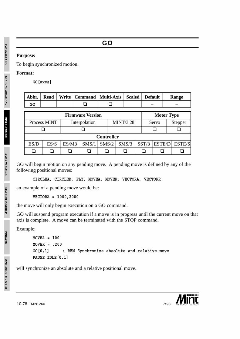
10-78 7/98MN1260
GO
Purpose:
To begin synchronized motion.
Format:
GO[axes]
Abbr. Read Write Command Multi-Axis Scaled Default Range
GO ❑ ❑ – –
Firmware Version Motor Type
Process MINT Interpolation MINT/3.28 Servo Stepper
❑ ❑ ❑ ❑
Controller
ES/D ES/S ES/M3 SMS/1 SMS/2 SMS/3 SST/3 ESTE/D ESTE/S
❑ ❑ ❑ ❑ ❑ ❑ ❑ ❑ ❑
GO will begin motion on any pending move. A pending move is defined by any of thefollowing positional moves:
CIRCLEA, CIRCLER, FLY, MOVEA, MOVER, VECTORA, VECTORR
an example of a pending move would be:
VECTORA = 1000,2000
the move will only begin execution on a GO command.
GO will suspend program execution if a move is in progress until the current move on thataxis is complete. A move can be terminated with the STOP command.
Example:
MOVEA = 100MOVER = ,200
GO[0,1] : REM Synchronize absolute and relative move
PAUSE IDLE[0,1]
will synchronize an absolute and a relative positional move.

10-797/98
GO will take into account the AXES string as in the following example:
AXES[0,1] : REM Default to axis 0 and 1
JOG.1 = 100 : REM Jog axis 1MA = 10 : GO : REM Absolute move on axis 0
will result in a motion in progress error. This can be solved as follows:
AXES[0,1] : REM Default to axis 0 and 1
JOG.1 = 100 : REM Jog axis 1MA = 10 : GO.0 : REM Explicit axis reference on GO
It is possible to synchronize moves off a digital input using the TRIGGER command asshown:
TRIGGER.1 = 1 : REM Trigger off input 1
MOVEA.1 = 100 : GO.1
The axis will move to position 100 when digital input 1 goes from active to inactive.
See section 6.3.6 for more detail on GO.
Note that move commands sent to a MINT/3.28 based controller will executeimmediately without the need for the GO command.
See also:
CIRCLEA, CIRCLER, FLY, IDLE, MODE, MOVEA, MOVECAM, MOVER, STOP,TRIGGER, VECTORA, VECTORR
GOSUB
Purpose:
To branch program execution to a subroutine.
Format:
GOSUB <subroutine_name>
Causes the program to branch to the subroutine with the label given by<subroutine_name>. Since MINT does not support line numbers, all subroutines arereferenced by labels. RETURN is used to resume execution from the statementimmediately following the GOSUB statement.
MN1260

10-80 7/98
Example:
GOSUB init
...END
#init
xpos = 0
ypos = 0fast = 100
slow = 10
RETURN
Notes:
Subroutines can be nested up to 20 levels deep i.e. a subroutine can call anothersubroutine which in turn can call another up to 20 levels.
A maximum of 40* labels can be defined for any given program.
A subroutine defined in the configuration file cannot be called from within theprogram file and vice versa.
GOSUB cannot be used on the command line.
See also:
#, GOTO, #IN0..#IN7, #ONERROR, RETURN, #STOP
MN1260

10-817/98
GOTO
Purpose:
To branch unconditionally out of the normal program sequence to a specified label.
Format:
GOTO label_name
Branches unconditionally to a specified label.
Example:
{ statements }GOTO label1
{statements }
#label1
GOTO should be used with care. Do not use GOTO to jump out of an interrupt routine,loops or block IFs. For example:
LOOP
...
IF IN1 DO
...IF IN2 THEN GOTO abortLoop
...
ENDIF
#abortLoop...
ENDL
will eventually result in a “Stack overflow” error message.
GOTO cannot be used on the command line.
See also:
#, GOSUB
MN1260
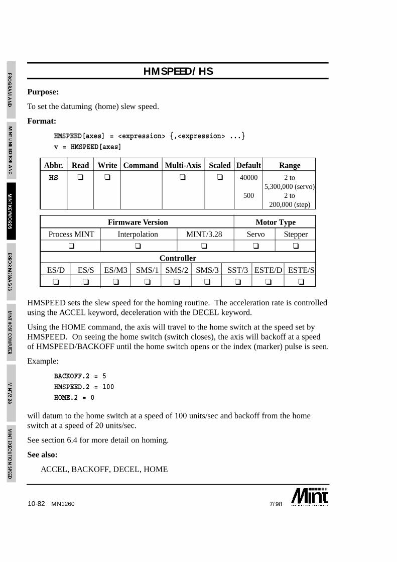
10-82 7/98MN1260
HMSPEED/HS
Purpose:
To set the datuming (home) slew speed.
Format:
HMSPEED[axes] = <expression> {,<expression> ...}
v = HMSPEED[axes]
Abbr. Read Write Command Multi-Axis Scaled Default Range
HS ❑ ❑ ❑ ❑ 40000 2 to 5,300,000 (servo)
500 2 to200,000 (step)
Firmware Version Motor Type
Process MINT Interpolation MINT/3.28 Servo Stepper
❑ ❑ ❑ ❑ ❑
Controller
ES/D ES/S ES/M3 SMS/1 SMS/2 SMS/3 SST/3 ESTE/D ESTE/S
❑ ❑ ❑ ❑ ❑ ❑ ❑ ❑ ❑
HMSPEED sets the slew speed for the homing routine. The acceleration rate is controlledusing the ACCEL keyword, deceleration with the DECEL keyword.
Using the HOME command, the axis will travel to the home switch at the speed set byHMSPEED. On seeing the home switch (switch closes), the axis will backoff at a speedof HMSPEED/BACKOFF until the home switch opens or the index (marker) pulse is seen.
Example:
BACKOFF.2 = 5
HMSPEED.2 = 100HOME.2 = 0
will datum to the home switch at a speed of 100 units/sec and backoff from the homeswitch at a speed of 20 units/sec.
See section 6.4 for more detail on homing.
See also:
ACCEL, BACKOFF, DECEL, HOME
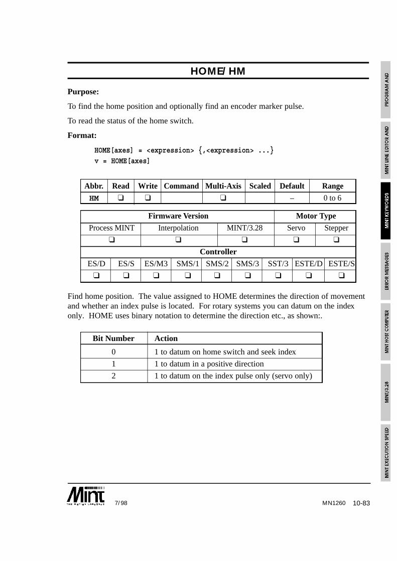
10-837/98 MN1260
HOME/HM
Purpose:
To find the home position and optionally find an encoder marker pulse.
To read the status of the home switch.
Format:
HOME[axes] = <expression> {,<expression> ...}v = HOME[axes]
Abbr. Read Write Command Multi-Axis Scaled Default Range
HM ❑ ❑ ❑ – 0 to 6
Firmware Version Motor Type
Process MINT Interpolation MINT/3.28 Servo Stepper
❑ ❑ ❑ ❑ ❑
Controller
ES/D ES/S ES/M3 SMS/1 SMS/2 SMS/3 SST/3 ESTE/D ESTE/S
❑ ❑ ❑ ❑ ❑ ❑ ❑ ❑ ❑
Find home position. The value assigned to HOME determines the direction of movementand whether an index pulse is located. For rotary systems you can datum on the indexonly. HOME uses binary notation to determine the direction etc., as shown:.
Bit Number Action
0 1 to datum on home switch and seek index
1 1 to datum in a positive direction
2 1 to datum on the index pulse only (servo only)

10-84 7/98MN1260
HOME values are:
Binary value Meaning
0 (0) Negative seek, datum on switch
0001 (1) Negative seek, datum on index (servo only)
0010 (2) Positive seek, datum on switch
0011 (3) Positive seek, datum on index (servo only)
0100 (4) Seek index pulse negative direction (servo only)
0110 (6) Seek index pulse positive direction (servo only)
Datuming slews at a speed set by the HMSPEED keyword and an acceleration rate set bythe ACCEL keyword. The axis will reverse off a home switch at a speed ofHMSPEED/BACKOFF.
Example:
HMPSEED.2 = 10
BACKOFF.2 = 5HOME.2 = 1
will datum to the home switch at a speed of 10 units/sec and then backoff at a speed of 2units/sec until the index (marker) pulse is seen.
Notes
• Datuming does not take into account RAMP.
• Reading HOME will return the value of the home switch.
• See section 6.4 for more detail on homing.
See also:
ACCEL, BACKOFF, HMSPEED, IDLE, MODE

10-857/98 MN1260
IDLE/IDPurpose:
To determine if motion has finished.
To set the idle following error (servo only).
Format:IDLE[axes] = <expression> {,<expression> ...}
v = IDLE[axis]
Abbr. Read Write Command Multi-Axis Scaled Default RangeID ❑ ❑ ❑ ❑ 16000 0 to 16000
Firmware Version Motor TypeProcess MINT Interpolation MINT/3.28 Servo Stepper
❑ ❑ ❑ ❑ ❑
ControllerES/D ES/S ES/M3 SMS/1 SMS/2 SMS/3 SST/3 ESTE/D ESTE/S
❑ ❑ ❑ ❑ ❑ ❑ ❑ ❑ ❑
Returns true (1) when controller is idle (mode of motion is zero).
Example:
HOME = 2,2
PAUSE IDLE[0,1]
This will home axes 0 and 1 and will wait for both axes to come to rest before continuingprogram execution.
Writing to IDLE defines the permissible following error (servo only) at which point amove is considered to be complete i.e.:
(MODE = _idle) AND (VELr <= VELw) AND (ABS(FOLERR) <= IDLEw)(where r is to show the read value of the variable and w the value written to it).
writing to VEL defines the velocity at which IDLE considers the motor to be stationary.By default, VEL is zero.
Example:
IDLE.0 = 10
MA.0 = 1000 : GO.0
PAUSE IDLE.0
the PAUSE IDLE statement will only terminate when profiling has stopped and thefollowing error is less than 10.
See also:
MODE, PAUSE
10-86 7/98
IF .. DO
Purpose:
To execute a series of instructions based on the value of an expression.
Format:
IF condition DO
...{ELSE
...}
ENDIF
Whereas the IF THEN statement can only be used to execute one line of commands, theblock IF structure can execute a series of commands.
If the condition is true, the statements up to the ELSE or ENDIF will be executed. If thecondition is false, the statements after the ELSE or ENDIF statement will be executed.ELSE is optional, statements following the ELSE will be executed only if the condition isfalse. Note the use of the keyword DO in place of THEN.
Example:
IF IN5 AND IN6 DO
FOR a = 1 TO 10
REM Move the position XYMOVEA = xpos(a), ypos(a) : GO
PAUSE IDLE[0,1] : REM Wait for axes to stop
OUT2 = _on : REM Set output
WAIT = 250 : REM Wait 1/4 secondOUT2 = _off : REM Output off
NEXT
ELSE
STOP[0,1]ENDIF
IF POS > 100 DO
INCA = MOVEA + newPos : REM Set new end position
PAUSE IDLEENDIF
IF DO statements can be nested up to 10 levels.
MN1260

10-877/98
If the statements can fit onto one line and no ELSE is required,IF .. THEN should be used for program speed.
See also:
IF..THEN
IF .. THEN
Purpose:
To execute a series of instructions based on the value of an expression.
Format:
IF <condition> THEN statements
If the condition is true the statements following THEN and up to the end of the line areexecuted. The condition can be any valid expression (see section 4.6 on relationaloperators).
Examples:
IF POS[0] > 100 AND POS[1] > 200 THEN STOP[0,1]
IF IN2 OR IN3 THEN GOSUB label1
Multiple statements are separated by colons and must be on the same line if they are to beexecuted in the same IF statement.
Example:
IF IN1 THEN OUT1 = 0 : OUT2 = 1
If the statements cannot fit onto one line or an ELSE clause is required,use the IF .. DO structure.
See also:
IF..DO
MN1260

10-88 7/98MN1260
IMASK/IM
Purpose:
To mask off MINT interrupts #IN0 to #IN7
Format:
IMASK = <expr>
v = IMASK
Abbr. Read Write Command Multi-Axis Scaled Default Range
IM ❑ ❑ 255 0 to 255
Firmware Version Motor Type
Process MINT Interpolation MINT/3.28 Servo Stepper
❑ ❑ ❑ ❑
Controller
ES/D ES/S ES/M3 SMS/1 SMS/2 SMS/3 SST/3 ESTE/D ESTE/S
❑ ❑ ❑ ❑ ❑ ❑ ❑ ❑ ❑
The IMASK variable is used to mask off selective MINT interrupts, #IN0 to #IN7.
Example:
To mask off interrupts #IN4 to #IN7 the following command is used:
IMASK = 000001111
DINT (disable interrupts) can be used first to ensure no interrupt is called before settingthe IMASK value.
In order for IMASK to take immediate effect within an interrupt routine, it must be placedimmediately following the label:
#IN0
IMASK = 011000000
…
RETURN
Reading IMASK will return the interrupt mask value.
IMASK can also be used to suspend a triggered move. See section 6.9 for details onTRIGGER.
See also:
DINT, EINT, IPEND, TRIGGER
10-897/98 MN1260
IN
Purpose:
To read the digital inputs as an 8 bit value.
Format:
v = IN
Abbr. Read Write Command Multi-Axis Scaled Default Range
IN ❑ – ❑ – –
Firmware Version Motor Type
Process MINT Interpolation MINT/3.28 Servo Stepper
❑ ❑ ❑ ❑ ❑
Controller
ES/D ES/S ES/M3 SMS/1 SMS/2 SMS/3 SST/3 ESTE/D ESTE/S
❑ ❑ ❑ ❑ ❑ ❑ ❑ ❑ ❑
Allows uncommitted user inputs 0 to 7 to be read as an eight bit binary number. This isuseful for reading dip switches attached to the digital inputs. Example:
BINARY IN
Prints the settings of the uncommitted user inputs to the screen.
Using bitwise arithmetic, individual bits can be tested:
IF IN & 15 THEN {statements}
if bits 0 to 3 are on then process the statement.
Individual bits can be accessed by adding the bit number to the IN keyword. For example:
a = IN1
will assign the value of input bit 1 to the variable a.
Alternatively, the dot notation can be used and a variable used to define the bit. Forexample:
a = 2
b = IN.a
will assign the value if IN2 to b. Note that if a is not within the range 0 <= a <= 7, thenan “Out of Range” error will result.

10-90 7/98MN1260
An interrupt routine can also be called in response to an input. See section 5.3.2 for moredetail.
See also:
ANALOGUE, #IN, IN0..7, OUT, XIO
IN0/I0 .. IN7/I7
Purpose:
To read the individual bit values of the digital inputs.
Format:
v = IN0
v = IN1
v = IN2
v = IN3
v = IN4v = IN5
v = IN6
v = IN7
Abbr. Read Write Command Multi-Axis Scaled Default Range
IO.. ❑ – –I7
Firmware Version Motor Type
Process MINT Interpolation MINT/3.28 Servo Stepper
❑ ❑ ❑ ❑ ❑
Controller
ES/D ES/S ES/M3 SMS/1 SMS/2 SMS/3 SST/3 ESTE/D ESTE/S
❑ ❑ ❑ ❑ ❑ ❑ ❑ ❑ ❑
Returns a value of either 0 or 1 for the input port 0 to 7, where 0 represents a groundedinput (connected to power if PNP inputs used).
Example:
my_var = IN3
Sets the user variable my_var to one if input 3 is high, or zero if low.

10-917/98 MN1260
Example 2:
IF IN2 OR IN3 THEN OUT1 = _on
If a #INx subroutine is defined, this will be called in response to a falling edge (atransition of 1 to 0 as seen by the controller) on the input. For example:
#IN2
STOP[0,1]PAUSE IDLE[0,1]
RETURN
See also:
ANALOGUE, #IN, OUT, XIO
INCA/IA
Format:
INCA[axes] = <expression> {,<expression> ... }v = INCA[axis]
Abbr. Read Write Command Multi-Axis Scaled Default Range
IA ❑ ❑ ❑ ❑ – -8388607 to8388607.0
Firmware Version Motor Type
Process MINT Interpolation MINT/3.28 Servo Stepper
❑ ❑ ❑ ❑ ❑
Controller
ES/D ES/S ES/M3 SMS/1 SMS/2 SMS/3 SST/3 ESTE/D ESTE/S
❑ ❑ ❑ ❑ ❑ ❑ ❑ ❑ ❑
Sets a new end position for the current positional move, MOVEA or MOVER, equal to theexpression. Given a positive move, the new position must be greater than the currentposition otherwise the current move will finish executing. Reading INCA will return trueor false to tell you whether the new end position has been set-up. If zero is returned thenew end position could not be set-up.

10-92 7/98
Example:
MOVEA = 100 :GO
PAUSE IN1 : REM Wait for an inputINCR = -10 : REM Set new end position
REM See of new end position setup otherwise perform a relative move.
IF !INCR THEN MOVER = -1 : GO
The new final position can beread by reading either MOVEAor MOVER.
Example:
On seeing an input, we want toset a new position of the currentmove equal to the currentposition plus a relative distance of 10.
PAUSE IN0 : REM Wait for the input
INCA = POS + 10
PAUSE IDLE
Reading the OFFSET keyword will return the remaining move length.
See also:
INCR, MOVEA, MOVER, OFFSET
MN1260

10-937/98 MN1260
INCR/IR
Format:
INCR[axes] = <expression> {,<expression> ... }
v = INCR[axis]
Abbr. Read Write Command Multi-Axis Scaled Default Range
IR ❑ ❑ ❑ ❑ – -8388607 to8388607.0
Firmware Version Motor Type
Process MINT Interpolation MINT/3.28 Servo Stepper
❑ ❑ ❑ ❑ ❑
Controller
ES/D ES/S ES/M3 SMS/1 SMS/2 SMS/3 SST/3 ESTE/D ESTE/S
❑ ❑ ❑ ❑ ❑ ❑ ❑ ❑ ❑
Extends or retracts the current positional move, MOVEA or MOVER, by the expressionvalue. Given a positive move, the new position must be greater than the current positionotherwise the current move will finish executing. Reading either INCR will return true orfalse to tell you whether the new end position has been set-up. If zero is returned the newend position could not be set-up.
Example:
MOVEA = 100 :GO
PAUSE IN1 : REM Wait for an input
INCR = -10 : REM Set new end position
REM See of new end position setup otherwise perform a relative move.
IF !INCR THEN MOVER = -1 : GO
The new final position can be readby reading either MOVEA orMOVER.

10-94 7/98
Example:
In a one axis rolling feed system, a second encoder, on axis 1, is used to detect slip.When the material is near the end of its move, we want to check for slip and correct for it.
PAUSE POS < nearEndPos
INCR = POS.0 - POS.1PAUSE IDLE
Note that axis 1 should be set to servo off mode (SERVOFF) or its axis turned off(CONFIG.1 = _off) to avoid following errors. Reading the OFFSET keyword will returnthe remaining move length.
See also:
INCA, MOVEA, MOVER, OFFSET
INKEY/IK
Purpose:
To read the next key in the serial/keypad buffer.
Format:
v = INKEY
Abbreviation:
IK
INKEY reads a single character from the serial port buffer. IF no character is present itwill return zero, otherwise it returns the ASCII value of the character. (ASCII is aninternational standard defining numeric equivalents to alphanumeric characters).
INKEY always returns the uppercase value of the characters A-Z. Thus:
my_var = INKEY
will return the value 65 (the ASCII value of ‘A’) to the variable my_var if the character ‘A’or ‘a’is present in the buffer.
MN1260
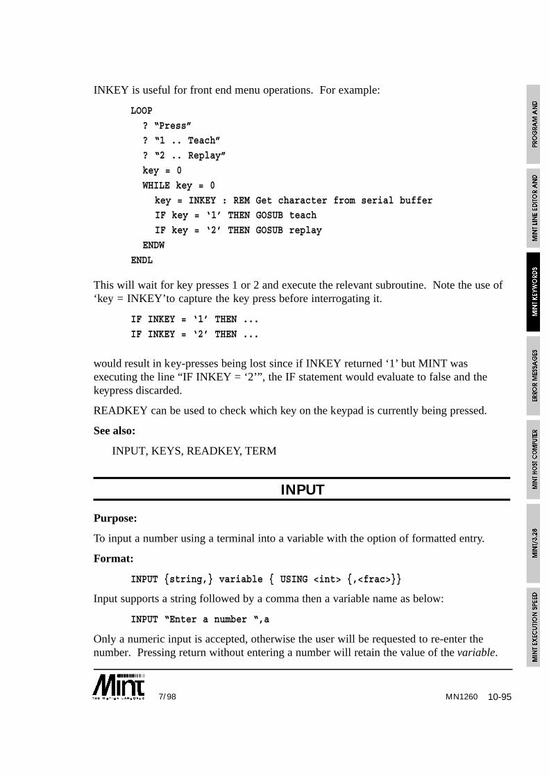
10-957/98
INKEY is useful for front end menu operations. For example:
LOOP
? “Press”? “1 .. Teach”
? “2 .. Replay”
key = 0
WHILE key = 0
key = INKEY : REM Get character from serial bufferIF key = ‘1’ THEN GOSUB teach
IF key = ‘2’ THEN GOSUB replay
ENDW
ENDL
This will wait for key presses 1 or 2 and execute the relevant subroutine. Note the use of‘key = INKEY’to capture the key press before interrogating it.
IF INKEY = ‘1’ THEN ...
IF INKEY = ‘2’ THEN ...
would result in key-presses being lost since if INKEY returned ‘1’ but MINT wasexecuting the line “IF INKEY = ‘2’”, the IF statement would evaluate to false and thekeypress discarded.
READKEY can be used to check which key on the keypad is currently being pressed.
See also:
INPUT, KEYS, READKEY, TERM
INPUT
Purpose:
To input a number using a terminal into a variable with the option of formatted entry.
Format:
INPUT {string,} variable { USING <int> {,<frac>}}
Input supports a string followed by a comma then a variable name as below:
INPUT “Enter a number “,a
Only a numeric input is accepted, otherwise the user will be requested to re-enter thenumber. Pressing return without entering a number will retain the value of the variable.
MN1260

10-96 7/98MN1260
The USING parameter allows for formatted input. <int> is the number of integer places toaccept and <frac> is the number of fractional places to accept. The number is prefixedwith zeros where necessary.
If <int> is positive, signed numbers will not be accepted. If <int> is negative, signednumbers are accepted. Pressing the ‘-’ key will toggle the sign of the number. The keysaccepted are:
Key Description
0 .. 9 Input number and move 1 char right. The decimal place will beskipped. The cursor returns to the beginning of the input when thelast character is entered.
‘-’ Toggle the sign of the number if <int> is negative otherwise ignore.The cursor will be places on the first number
‘.’ Move to the first number after the decimal place.
space Move one character to the right
del Delete the number and place a zero in its place. Move the cursor onecharacter to the left.
Example:
INPUT “A = “, a USING -5,2
Accept formatted signed input with 5 decimal places and 2 fractional places, i.e.±99999.99
To provide feedback when using the keypad and display, use the BEEPON keyword. Thiswill sound the buzzer each time a key is pressed when using the INPUT statement.
See also:
BEEPOFF, BEEPON, INKEY, LOCATE, PRINT
INT
Purpose:
To return the integer value of an expression.
Format:
v = INT(<expression>)
Strips a MINT scaled integer of its fractional part. The expression can be any valid MINTexpression.

10-977/98 MN1260
Example:
PRINT INT(12.4 + 3.2)
will print 15 to the operator terminal.
? INT POS
will print the integer part of the position.
INT will effectively round down. To round to the nearest integer, add 0.5 to theexpression:
? INT(POS + .5)
will round the position up if the fractional part is greater than .5 otherwise round theposition down.
See also:
ABS
IPEND/IP
Purpose:
To read or clear pending MINT interrupts
Format:
IPEND = <expr>
v = IPEND
Abbr. Read Write Command Multi-Axis Scaled Default Range
IP ❑ ❑ ❑ – 0 to 255
Firmware Version Motor Type
Process MINT Interpolation MINT/3.28 Servo Stepper
❑ ❑ ❑ ❑
Controller
ES/D ES/S ES/M3 SMS/1 SMS/2 SMS/3 SST/3 ESTE/D ESTE/S
❑ ❑ ❑ ❑ ❑ ❑ ❑ ❑ ❑
Reading IPEND will return all pending interrupts (#IN0 to #IN7). For example, if IPENDreturns 3 (011), then interrupts #IN0 and #IN1 are pending.

10-98 7/98MN1260
Writing to IPEND will clear or cause interrupts. For example:
IPEND = IPEND & 011111100
will clear interrupts #IN0 and #IN1
IPEND can also be used to clear a triggered move. See section 6.9 for details onTRIGGER.
See also:
DIN, EINT, IMASK, TRIGGER
JOG/JG
Purpose:
To set an axis for integral speed control.
Format:
JOG[axes] = <expression> {,<expression> ...}
v = JOG[axis]
Abbr. Read Write Command Multi-Axis Scaled Default Range
JG ❑ ❑ ❑ ❑ – -5300000.0 to5300000.0
Firmware Version Motor Type
Process MINT Interpolation MINT/3.28 Servo Stepper
❑ ❑ ❑ ❑ ❑
Controller
ES/D ES/S ES/M3 SMS/1 SMS/2 SMS/3 SST/3 ESTE/D ESTE/S
❑ ❑ ❑ ❑ ❑ ❑ ❑ ❑ ❑
JOG is used to set up integral speed control. JOG will accelerate/decelerate to speed atthe acceleration rate set by ACCEL but will not take into account RAMP, the accelerationramp smooth factor.

10-997/98
The JOG command can be executed at any time. If a move of a different time is alreadyin progress, the axis will go into JOG mode and accelerate or decelerate to its new speed.For example:
MOVEA.0 = 100 : GO.0
PAUSE IN1JOG.0 = -20
JOG is terminated with either the STOP command or by assigning a value of 0 to JOG.This will bring the axis to a controlled stop.
Example:
Assuming the SCALE has been set to revs.
JOG = 10
will jog the motor at a constant speed of 10 revs/s.
JOG = -10
will jog the motor in a negative direction at a speed of 10 revs/s. The motor willdecelerate to a stop from its previous speed and accelerate to the new speed.
Example 2:
JOG = 20 : REM Jog at 20 units/sec
PAUSE IN1 : REM Wait for input 1
STOP : REM Stop motion
PAUSE IDLE : REM Wait for axis to stopMA = 10 : GO : REM Perform an absolute positional move
note the use of PAUSE IDLE to wait for the axis to stop before setting up the absolutepositional move.
Using the TRIGGER keyword, a JOG move can be initiated on an input. For example:
TRIGGER.1 = 1
JOG.1 = 100
When the input goes low, the motor will start jogging. This is the same as:
#IN1
JOG.1 = 100
RETURN
See also:
ACCEL, MODE, SCALE, STOP, TRIGGER, VEL
MN1260

10-100 7/98MN1260
KEYS
Purpose:
To format and enable the keypad and display.
Format:
KEYS “ASCII Characters”
The KEYS keyword allows you to configure your own keypad for any particular ASCIIcharacters in an 8x8 array. The ASCII string following the keyword will define the keys.If you are using a 4x4 keypad for example, you need to map the keys onto the 8x8 matrixas shown in the example:
Assume you are using a 4x4 keypad and require the following layout:
9 8 7 A
6 5 4 B
3 2 1 <CR>
– 0 . <BS>
where <CR> is carriage return, and <BS> is backspace or delete.
The KEYS keyword will be defined as follows:
KEYS “[email protected].~....................................”REM | row 1 | row 2 | row 3 | row 4 | row 5 | row 6 | row 7 | row 8 |
This corresponds to the following 8x8 matrix:
9 8 7 A . . . .
6 5 4 B . . . .
3 2 1 <CR> . . . .
– 0 . <BS> . . . .
. . . . . . . .
. . . . . . . .
. . . . . . . .
. . . . . . . .
If keys are not used within the 8x8 matrix, they must be padded out with an arbitrarycharacter. In this case a decimal dot is used.
Since <CR> and <BS> are not directly supported using a standard keyboard, KEYS willinterpret ‘@’ as carriage return and will return ASCII code 13. ‘~’ is used to interpretback space and will return ASCII code 8.

10-1017/98 MN1260
To use the standard keypad setting just type the following:
KEYS “”
Do not insert any characters within the quotes unless you wish to change to standardkeypad layout which is defined as:
See READKEY below for details on the keys and their associated ASCII value for theoperator keypad.
If you are using your own keypad, please refer to its data sheet for its row/columnconfiguration. The connections must be made to the appropriate row/column pins on theinterface card. The keypad adapter is discussed in detail in the hardware guide.
See also:
INKEY, READKEY
KINT/KI
Purpose:
To set the servo loop integral gain term.
Format:
KINT[axes] = <expression> {,<expression> ...}
v = KINT[axis]
Abbr. Read Write Command Multi-Axis Scaled Default Range
KI ❑ ❑ ❑ ❑ 0 to 255.0
Firmware Version Motor Type
Process MINT Interpolation MINT/3.28 Servo Stepper
❑ ❑ ❑ ❑
Controller
ES/D ES/S ES/M3 SMS/1 SMS/2 SMS/3 SST/3 ESTE/D ESTE/S
❑ ❑ ❑ ❑ ❑ ❑
Integral gain is used to overcome constant motor loading such as gravity on a vertical tablebut can be used to overcome steady state following errors in other applications. KINTwould not normally be used for velocity drives since steady state errors are usually overcomeby the drive itself. See the Getting Started Guide for details on setting this parameter.

10-102 7/98MN1260
The effect of the integral gain on the DAC output can be reduced by setting theKINTRANGE parameter otherwise instability may arise. KINT is usually found to have avalue of approximately GAIN/10.
The effects of the servo loop parameters can be monitored using the AUX keyword and anoscilloscope.
Example:
GAIN = 1;
KR = 20; : REM KINT only has 20% effect on DACKINT = .1;
DEFAULT can be used to set all servo loop gains to zero.
KINT should only be set once all other servo gainparameters have been correctly set-up.
See also:
AUX, CURRLIMIT, DAC, DEFAULT, DEMAND, GAIN, KINTRANGE, KVEL,KVELFF, MFOLERR, TORQUE
KINTRANGE/KR
Purpose:
To restrict overall effect the integral gain has on the DAC output.
Format:
KINTRANGE[axes] = <expression> {,<expression> ...}
v = KINTRANGE[axis]
Abbr. Read Write Command Multi-Axis Scaled Default Range
KI ❑ ❑ ❑ ❑ 0 to 255.0
Firmware Version Motor Type
Process MINT Interpolation MINT/3.28 Servo Stepper
❑ ❑ ❑ ❑
Controller
ES/D ES/S ES/M3 SMS/1 SMS/2 SMS/3 SST/3 ESTE/D ESTE/S
❑ ❑ ❑ ❑ ❑ ❑
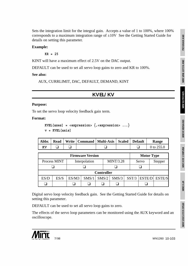
10-1037/98 MN1260
Sets the integration limit for the integral gain. Accepts a value of 1 to 100%, where 100%corresponds to a maximum integration range of ±10V See the Getting Started Guide fordetails on setting this parameter.
Example:
KR = 25
KINT will have a maximum effect of 2.5V on the DAC output.
DEFAULT can be used to set all servo loop gains to zero and KR to 100%.
See also:
AUX, CURRLIMIT, DAC, DEFAULT, DEMAND, KINT
KVEL/KV
Purpose:
To set the servo loop velocity feedback gain term.
Format:
KVEL[axes] = <expression> {,<expression> ...}
v = KVEL[axis]
Abbr. Read Write Command Multi-Axis Scaled Default Range
KV ❑ ❑ ❑ ❑ 0 to 255.0
Firmware Version Motor Type
Process MINT Interpolation MINT/3.28 Servo Stepper
❑ ❑ ❑ ❑
Controller
ES/D ES/S ES/M3 SMS/1 SMS/2 SMS/3 SST/3 ESTE/D ESTE/S
❑ ❑ ❑ ❑ ❑ ❑
Digital servo loop velocity feedback gain. See the Getting Started Guide for details onsetting this parameter.
DEFAULT can be used to set all servo loop gains to zero.
The effects of the servo loop parameters can be monitored using the AUX keyword and anoscilloscope.

10-104 7/98MN1260
See also:
AUX, CURRLIMIT, DAC, DEFAULT, DEMAND, GAIN, KINT, KVELFF, TORQUE
KVELFF/KF
Purpose:
To set the servo loop velocity feedforward gain term.
Format:
KVELFF[axes] = <expression> {,<expression> ...}v = KVELFF[axis]
Abbr. Read Write Command Multi-Axis Scaled Default Range
KF ❑ ❑ ❑ ❑ 0 to 255.0
Firmware Version Motor Type
Process MINT Interpolation MINT/3.28 Servo Stepper
❑ ❑ ❑ ❑
Controller
ES/D ES/S ES/M3 SMS/1 SMS/2 SMS/3 SST/3 ESTE/D ESTE/S
❑ ❑ ❑ ❑ ❑ ❑
Digital servo loop velocity feedforward gain. See the Getting Started Guide for details onsetting this parameter.
Example:
KVELFF = 10.5;
Example 2:
KVELFF = KVEL
can be used for a current amplifier to reduce the following error during constant motion.See the Getting Started Guide for further detail.
DEFAULT can be used to set all servo loop gains to zero.
The effects of the servo loop parameters can be monitored using the AUX keyword and anoscilloscope. Alternatively, cTERM for Windows can be used.
See also:
AUX, CURRLIMIT, DAC, DEFAULT, DEMAND, GAIN, KINT, KVEL, TORQUE

10-1057/98 MN1260
LASTERRPurpose:
To display the last error message that resulted in abnormal program termination.
Format:
LASTERR
Typing LASTERR at the command line will display the last error that resulted in programtermination. This is useful in stand-alone systems where a terminal is not connected to thecontroller. If a programming error does occur, the LED status display will show an ‘E’.
See also:
ERROR, ERR, ERRAXIS
LED/LDPurpose:
To set the 7 segment LED display to show the status of a particular axis.
Format:LED = <expression>
v = LED
Abbr. Read Write Command Multi-Axis Scaled Default Range
LD ❑ ❑ 0 0 to 3
Firmware Version Motor Type
Process MINT Interpolation MINT/3.28 Servo Stepper
❑ ❑ ❑ ❑ ❑
Controller
ES/D ES/S ES/M3 SMS/1 SMS/2 SMS/3 SST/3 ESTE/D ESTE/S
❑ ❑ ❑ ❑ ❑ ❑ ❑ ❑ ❑
Since there is only one LED status display, the LED keyword is used to show the status of theassigned axis to the display. Note that axis 1 will light the decimal dot on the LED display.
LED = 2
will show the status of axis 2 on the LED display.
Reading the LED keyword will return the value assigned to it.
See also:
ERROR, MODE

10-106 7/98MN1260
LIMIT/LM
Purpose:
To read the status of the limit (end of travel) inputs.
Format:
v = LIMIT[axis]
Abbr. Read Write Command Multi-Axis Scaled Default Range
LM ❑ ❑ – –
Firmware Version Motor Type
Process MINT Interpolation MINT/3.28 Servo Stepper
❑ ❑ ❑ ❑ ❑
Controller
ES/D ES/S ES/M3 SMS/1 SMS/2 SMS/3 SST/3 ESTE/D ESTE/S
❑ ❑ ❑ ❑ ❑ ❑ ❑ ❑ ❑
LIMIT returns the status of the limit switch inputs. The keyword accepts axis parametersin the normal manner. For example:
a = LIMIT.1
returns 1 to variable a if the limit input on axis 1 is asserted, 0 if the input is negated.
#ONERROR
REM Check for a limit error
IF ERROR.0 = _limit | ERROR.1 = _limit DO
DISLIMIT[0,1] : REM Disable limits and clear errorSERVOFF[0,1] : REM Turn servos off
PAUSE LIMIT[0,1] : REM Wait to move off limits
SERVOC[0,1] : REM Servo on
ENLIMIT[0,1] : REM Enable the limits
ENDIFRETURN
shows the use of LIMIT within an ONERROR routine.
If the limits are disabled with DISLIMIT, their value can still be read using the LIMITkeyword.
See also:
ERROR, DISLIMIT, #ONERROR, PAUSE

10-1077/98
LINE
Purpose:
To write a string to a specified line on the terminal, clearing all characters to the end ofthe line.
Format:
LINE <line number>, <expression>
The LINE command will print the expression at the specified line on the display and thenclear the display to the end of that line (assuming 20 characters per line). The cursor isreturned to the end of the printed text.
The expression can be any expression supported by PRINT and will allow the use of theUSING parameter for formatted output. For example:
LINE 2, “A = “, a USING 5,2
will print the value of a at line 2 with formatted output.
Example
LINE 1,” EXIT”LINE 2,”Main Menu”
LINE 3,”Select Function”
LINE 4,”SETUP START MANUAL”,
Note the use of the comma at the end of the line to suppressline feeding which results in the display clearing.
See also:
LOCATE, PRINT
MN1260

10-108 7/98MN1260
LOAD
Purpose:
To load a file into the controller using a terminal editor other than cTERM or to load arraydata into an executing program.
Format:
LOAD <buffer>
LOAD can be used to load programs and data into the controller if cTERM is not used.Buffer corresponds to:
Value Buffer
-3 Load array data from memory card if fitted
-2 Load configuration file from memory card if fitted
-1 Load program from memory card if fitted
1 Program buffer, no checksum
2 Configuration buffer, no checksum
3 Array data, no checksum
4 Program buffer with checksum
5 Configuration buffer with checksum
6 Array data with checksum
LOAD can also be used within a program for downloading array data into an executingprogram.
Example:
{ statements }
IF INKEY = ‘L’ THEN GOSUB getData
{ statements }
END#getData
TIME = 0
REPEAT
IF INKEY = ‘3’ THEN : ? “Ok 3”: LOAD 3 : RETURNUNTIL TIME > 1000 : REM TImeout after 1000ms
RETURN

10-1097/98
on receiving an ‘L’, the subroutine getData will be called. If ‘3’ is received the data willbe loaded, otherwise the routine will time-out. This can be used with cTERM which onfile load will send down the string “LOAD” followed by “3” for array data. cTERM willthen expect the response “Ok 3” before downloading the data.
Buffer values 4 to 6 should only be used with cTERM which provides a checksum tocheck for data corruption. Always send “Ok 1” to “Ok 3” in acknowledgement and not“Ok 4” to “Ok 6”.
Data can be loaded to the memory simply using the LOAD command. In order to retrievethe array data from the memory card
LOAD -3
is used.
The upload/download routines as used within cTERM for DOS can be found on theaccompanying diskette. These are written in Turbo C but should be portable among mostC compilers. Alternatively the MINT Interface Library provides functions for Windowsfor many of the popular development suites.
See also:
DIM, DISPLAY, SAVE
LOCATE
Purpose:
To locate the cursor on a VT100 (or VT52) terminal or the LCD display.
Format:
LOCATE <x>,<y>
Using VT100 (or VT52; see TERM) emulation, the cursor is located at column <x>, row<y>, where the top left corner is at location column 1, row 1. <x> and <y> are not rangechecked. The cursor will remain stationary if <x> or <y> are out of bounds of the screenco-ordinates. Example:
LOCATE 10,10 : PRINT “Column 10, Row 10”
The string “Column 10, Row 10” will be printed at column 10, row 10.
<x> and <y> can be any valid MINT expression. If an LCD terminal is connected, thecursor will be located at the given co-ordinates.
See also:
BOL, CLS, INPUT, LINE, PRINT, TERM
MN1260

10-110 7/98
LOOP .. ENDL
Purpose:
To perform an endless loop.
Format:
LOOP{statements}
ENDL
This is the simplest type of loop in MINT, it loops round forever, for instance:
LOOP
JOG = ANALOGUE1/100
ENDL
loops round forever reading analog input one and jogging the motor to a maximum valueof 10.
Notes:
A loop can be terminated by use of the EXIT keyword.
LOOPs can be nested up to 10 levels deep.
See also:
EXIT, FOR..NEXT, REPEAT..UNTIL, WHILE..ENDW
MN1260

10-1117/98 MN1260
LOOPTIME/LT
Purpose:
To set the servo loop time and the number of axes supported.
Format:
LOOPTIME = <expression>
Abbr. Read Write Command Multi-Axis Scaled Default Range
LT ❑ ❑ 2 1 to 2
Firmware Version Motor Type
Process MINT Interpolation MINT/3.28 Servo Stepper
❑ ❑ ❑ ❑
Controller
ES/D ES/S ES/M3 SMS/1 SMS/2 SMS/3 SST/3 ESTE/D ESTE/S
❑ ❑ ❑ ❑ ❑ ❑
Sets the loop closure time and the number of axes supported by MINT. SettingLOOPTIME to 1 will give a loop closure time of 1 ms for one axis of servo control. Thesecond encoder is still accessible using the POS or ENCODER keyword.
LT = 1
A LOOPTIME of 2 will set a loop closure time of 2ms and support 3 axes of motion.
DEFAULT will set LOOPTIME to 2.
See also:
AXES, DEFAULT, TIME
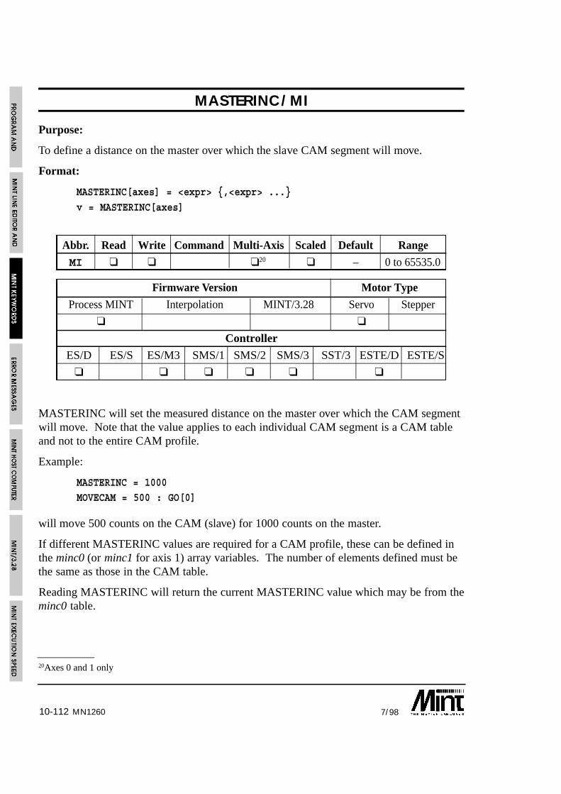
10-112 7/98MN1260
20Axes 0 and 1 only
MASTERINC/MI
Purpose:
To define a distance on the master over which the slave CAM segment will move.
Format:
MASTERINC[axes] = <expr> {,<expr> ...}
v = MASTERINC[axes]
Abbr. Read Write Command Multi-Axis Scaled Default Range
MI ❑ ❑ ❑20 ❑ – 0 to 65535.0
Firmware Version Motor Type
Process MINT Interpolation MINT/3.28 Servo Stepper
❑ ❑
Controller
ES/D ES/S ES/M3 SMS/1 SMS/2 SMS/3 SST/3 ESTE/D ESTE/S
❑ ❑ ❑ ❑ ❑ ❑
MASTERINC will set the measured distance on the master over which the CAM segmentwill move. Note that the value applies to each individual CAM segment is a CAM tableand not to the entire CAM profile.
Example:
MASTERINC = 1000MOVECAM = 500 : GO[0]
will move 500 counts on the CAM (slave) for 1000 counts on the master.
If different MASTERINC values are required for a CAM profile, these can be defined inthe minc0 (or minc1 for axis 1) array variables. The number of elements defined must bethe same as those in the CAM table.
Reading MASTERINC will return the current MASTERINC value which may be from theminc0 table.

10-1137/98 MN1260
Notes:
The MASTERINC value and those defined in the array (mincX() ) must be positive.
If the slave is following an external encoder, the MASTERINC values will be scaledby the scale factor (SCALE) of the external encoder axis. For example:
FOLLOWAXIS.0 = 1 : REM Slave axis 0 to follow axis 1
SCALE[0,1] = 100,200 : REM Scale slave and master to mmMASTERINC = 10 : REM Master increment given as 10mm
: REM equivalent to 10*200 quad counts
The scale factor SCALE[FOLLOWAXIS[axis]] is used for the conversion.
If the master input reference is given by the SPEED (FA = -1), the pulse timer input (FA =-2) or one of the 3 channel encoder inputs (FOLLOWAXIS = 3,4,5), MASTERINC mustbe given in quadrature counts.
See also:
CAM, FOLLOWAXIS, MOVECAM
MFOLERR/MF
Purpose:
To set the maximum permissible following error before an error is generated.
Format:
MFOLERR[axes] = <expression> {,<expression> ...}
a = MFOLERR[axis]
Abbr. Read Write Command Multi-Axis Scaled Default Range
MF ❑ ❑ ❑ ❑ 16000 0 to 32767.0
Firmware Version Motor Type
Process MINT Interpolation MINT/3.28 Servo Stepper
❑ ❑ ❑ ❑
Controller
ES/D ES/S ES/M3 SMS/1 SMS/2 SMS/3 SST/3 ESTE/D ESTE/S
❑ ❑ ❑ ❑ ❑ ❑

10-114 7/98MN1260
Sets the maximum permissible following error before an error is generated. The followingerror is defined as the demand position (where you want to be) minus the actual motorposition (where you are). If the following error exceeds the value set by MFOLERR(maximum following error) an error is generated which is shown by an ‘F’ on the LCDdisplay and the ERROR keyword will be set to 2. If an ONERROR routine is defined,this will be called otherwise program execution will be aborted with the error message:
ERROR: Program: Following error on axis Y at line XXX
Example:
SCALE = 500; : REM Scale to mm
MFOLERR = 4; : REM Max following error = 4mm
should the following exceed 4mm, an error will be generated.
See also:
AXISCON, ERROR, FOLERR, SCALE
MODE/MD
Purpose:
To return the current mode of motion.
Format:
v = MODE[axis]
Abbr. Read Write Command Multi-Axis Scaled Default Range
MD ❑ ❑ – 0 to 20
Firmware Version Motor Type
Process MINT Interpolation MINT/3.28 Servo Stepper
❑ ❑ ❑ ❑ ❑
Controller
ES/D ES/S ES/M3 SMS/1 SMS/2 SMS/3 SST/3 ESTE/D ESTE/S
❑ ❑ ❑ ❑ ❑ ❑ ❑ ❑ ❑

10-1157/98 MN1260
Returns the current mode of motion on the axis specified. Modes are as follows:
Code Constant Status LED Meaning Set by (MINT keyword)0 _idle 8 Idle1 _servoff – Servo amplifier power off SERVOFF2 _linear P Linear positional move MOVEA/MOVER,
VECTORA/VECTORR3 _jog J Jogging. JOG4 _circular C Circular interpolation CIRCLEA/CIRCLER5 _pulse U Pulse following PULSE6 _torque q Torque control TORQUE7 _homing H Homing (datuming) HOME8 _offset o Offset OFFSET9 _follow Æ Follow mode FOLLOW
10 reserved11 c Cam segment MOVECAM12 reserved13 reserved14 reserved15 F Flying shear FLY16 c Cam table execution CAMA/CAM17 J Joystick mode JY
(MINT/3.28, stepper only)18 g High resolution gear ratio GEARN19 reserved20 reserved
MINT constants can be used as shown::
PULSE = 1
PAUSE IN1OFFSET = 10
PAUSE MODE = 5
can be replaced by:
PULSE = 1PAUSE IN1
OFFSET = 10
PAUSE MODE = _pulse
during an OFFSET command.
10-116 7/98MN1260
To check when a move has finished execution, the following can be used:
MA[0,2] = 1000,-3000 : GO[0,2]
PAUSE MODE.0 = _idle AND MODE.2 = _idle
can be replaced by:
MA[0,2] = 1000,-3000 : GO[0,2]
PAUSE IDLE[0,1]
which detects when the motor has physically come to reset to within a user definedfollowing error rather than detecting the end of profiling.
See also:
IDLE, LED, TRIGGER
MOVEA/MA
Purpose:
To set up a positional move to an absolute position.
Format:
MOVEA[axes] = <expression> {,<expression ...}
v = MOVEA[axis]
Abbr. Read Write Command Multi-Axis Scaled Default Range
MA ❑ ❑ ❑ ❑ – -8388607 to8388607.0
Firmware Version Motor Type
Process MINT Interpolation MINT/3.28 Servo Stepper
❑ ❑ ❑ ❑ ❑
Controller
ES/D ES/S ES/M3 SMS/1 SMS/2 SMS/3 SST/3 ESTE/D ESTE/S
❑ ❑ ❑ ❑ ❑ ❑ ❑ ❑ ❑
Sets an absolute positional move. The command will be accepted during a currentpositional move (CIRCLEA/R, MOVEA/R, VECTORA/R) but will not be executed untilthe next GO statement.

10-1177/98
Example:
MOVEA[2] = -50 : GO[2]
Moves axis two to absolute position -50 counts from datum (zero point).
MA = 100,200 : GO
moves to absolute position 100,200 from the zero position. Reading MOVEA will returnthe desired end position.
MOVEA = 100,200 : GO[0,1]
PRINT MOVEA.0;MOVEA.1
will print:
100 200
Setting AXISCON bit 3 to 1 will allow MOVEA to return the target position from theprofile generator. This value is passed to the servo/stepper control loop every cycle(typically 2ms) and determines the position of the motor.
The positional move will follow the velocity profile defined by ACCEL, SPEED andRAMP. During a positional move, the slew speed can be changed using the SPEEDkeyword. The end position of the current move can be altered using either the INCA orINCR keywords. For example:
MOVEA = 10 : GO
PAUSE IN1INCA = 20
PAUSE IDLE
will set the end position to 20 on seeing digital input 1.
Reading the OFFSET keyword during a positional move will return the remaining movelength. For example, assuming a start position of 100:
MA = 200 : GO
? OFFSET
will return 100 since this is the length of the move in operation i.e. from position 100 to200.
MA = 200 : GO
PAUSE POS >= 170
? OFFSET
will return a value of approximately 30. Note that OFFSET always returns a positivenumber regardless of the direction of motion.
MN1260

10-118 7/98MN1260
See also:
ACCEL, AXISCON, CIRCLEA, CIRCLER, FLY, GO, INCA, INCR, MOVER,OFFSET, RAMP, SPEED, STOP, TRIGGER, VECTORA, VECTORA
MOVER/MR
Purpose:
To set up a positional move to a position relative from the current position.
Format:
MOVER[axes] = <expression> {,<expression> ...}v = MOVER[axis]
Abbr. Read Write Command Multi-Axis Scaled Default Range
MR ❑ ❑ ❑ ❑ – -8388607 to8388607.0
Firmware Version Motor Type
Process MINT Interpolation MINT/3.28 Servo Stepper
❑ ❑ ❑ ❑ ❑
Controller
ES/D ES/S ES/M3 SMS/1 SMS/2 SMS/3 SST/3 ESTE/D ESTE/S
❑ ❑ ❑ ❑ ❑ ❑ ❑ ❑ ❑
Sets up a relative positional move. The command will be accepted during a currentpositional move (CIRCLEA/R, MOVEA/R, VECTORA/R) but will not be executed untilthe next GO statement. If the desired end position is greater than 223 counts, the positioncounter will wrap round. If for example a move is set up that goes beyond position +223,MOVER will return a value in the region of -223.
Example:
MOVER[2] = -50 : GO : REM Assuming AXES[0,1,2]
Moves axis two 50 counts from the present position in a negative direction.
The positional move will follow the velocity profile defined by ACCEL, SPEED andRAMP. During a positional move, the slew speed can be changed using the SPEEDkeyword.
10-1197/98
The end position of the current move can be altered using either the INCA or INCRkeywords. For example:
MOVER = 10 : GO
PAUSE IN1INCR = 20
PAUSE IDLE
will set a relative end position of 20 on seeing digital input 1.
Reading the OFFSET keyword during a positional move will return the remaining movelength. For example:
MR = 200 : GO
? OFFSET
will return 200 i.e. the length of the move in operation.
MR = 200 : GOPAUSE POS >= 170
? OFFSET
will return a value of approximately 30. Note that OFFSET always returns a positivenumber regardless of the direction of motion.
The OFFSET keyword is useful in indexing applications to determine how much of theindex is remaining. For example: in an indexing application, an output must be set 30mmbefore the end of the move where each index is 100mm in length:
LOOP
MOVER = 100 : GOPAUSE OFFSET <= 30 : REM Wait for 30mm before end
OUT1 = 1 : REM Set output
PAUSE IDLE : REM Wait to stop
OUT1 = 0 : REM Clear outputENDL
See also:
ACCEL, CIRCLEA, CIRCLER, GO, INCA, INCR, MOVEA, OFFSET, RAMP,SPEED, STOP, TRIGGER, VECTORA, VECTORA
MN1260
10-120 7/98MN1260
MP
Purpose:
To return the mode of motion in the move buffer.
Abbr. Read Write Command Multi-Axis Scaled Default Range
MP ❑ ❑ – –
Firmware Version Motor Type
Process MINT Interpolation MINT/3.28 Servo Stepper
❑ ❑ ❑
Controller
ES/D ES/S ES/M3 SMS/1 SMS/2 SMS/3 SST/3 ESTE/D ESTE/S
❑ ❑ ❑ ❑ ❑ ❑ ❑ ❑ ❑
If two moves are set-up without waiting for the first move to complete, the second movewill be buffered. In MINT/3.28, if a third move is sent, a NAK will result. In order todetermine when the buffer is free, the MP keyword can be read. If it returns 0, then thebuffer is free for the next move.
See also:
MODE, ZZ
NOT/!
Purpose:
To perform a logical not on an expression.
Format:
v = NOT <expr>
Abbreviation:
!

10-1217/98 MN1260
Logical NOT. If <expr> is true (non-zero) NOT <expr> will be 0 as shown in the table:
<expr> NOT <expr>
0 1
1 0
NOT is very useful when testing the state of binary inputs. For example:
IF !IN1 THEN OUT1 = 1
is the same as
IF IN1 = 0 THEN OUT1 = 1
The first expression however uses less code space and is quicker to execute.
Note that the expression:
IF A NOT = B THEN {statement}
is not valid, instead use:
IF A <> B THEN {statement}
See also:
AND, OR
OFFLINE
Purpose:
To define an off-line array. The array values are stored off-line on a memory card
Format:
DIM OFFLINE var( elements )

10-122 7/98MN1260
The OFFLINE keyword is used in conjunction with the DIM statement to specify off-linearray data.
DIM OFFLINE xpos(1000)
DIM OFFLINE ypos(1000)DIM data(50)
SERVOFF
FOR a = 1 TO 1000
PAUSE IN1 : REM Wait for input 1xpos(a) = POS.0 : ypos(a) = POS.1
NEXT
The array data xpos and ypos have both been defined as residing off-line on the memorycard by use of the OFFLINE keyword within the DIM statement. The array data can thenbe used throughout the program as though the data resides within the controller addressspace.
Off-line array data is discussed in detail in section 4.5.1.
See also:
DIM
OFFSET/OF
Purpose:
To perform a positional offset during pulse or encoder following.
Format:
OFFSET[axes] = <expression> {,<expression> ...}v = OFFSET[axis]
Abbr. Read Write Command Multi-Axis Scaled Default Range
OF ❑ ❑ ❑ ❑ – -8388607 to8388607.0
Firmware Version Motor Type
Process MINT Interpolation MINT/3.28 Servo Stepper
❑ ❑ ❑ ❑ ❑
Controller
ES/D ES/S ES/M3 SMS/1 SMS/2 SMS/3 SST/3 ESTE/D ESTE/S
❑ ❑ ❑ ❑ ❑ ❑ ❑ ❑ ❑

10-1237/98
Performs an offset during pulse or encoder following, i.e. an offset is performed on a basespeed. The axis must be in PULSE or FOLLOW mode. Note that GO is not required.However if an OFFSET is set up while an OFFSET is being performed, MINT will issuean “Motion in progress error”. OFFSET is ignored if MODE is IDLE.
From esMINT v2.71, can OFFSET can be performed on FLY.
OFFSET is the same as a relative move i.e. it follows a velocity profile, therefore allparameters such as SPEED, ACCEL and RAMP will affect the profile. Note that SPEEDdefines the relative speed from the base speed.
OFFSET = 10 : REM Perform move
PAUSE MODE = _pulse: REM Wait for offset to finish
The LED will show a small ( when performing an offset.
Reading OFFSET will return the remaining vector size of the offset beingperformed or of an positional move (MOVEA/R, CIRCLEA/R,VECTORA/R). Note that the sign gives the direction of motion.
Reading the OFFSET keyword during a positional move will return the remaining movelength. For example:
MR = 200 : GO
? OFFSET
will return 200 i.e. the length of the move in operation.
POS.0 = 0
MA.0 = 200 : GO.0PAUSE POS.0 >= 170
? OFFSET.0
will return a value of approximately 30.
The OFFSET keyword is useful in indexing applications to determine how much of theindex is remaining. For example: in an indexing application, an output must be set 30mmbefore the end of the move where each index is 100mm in length:
LOOP
MOVER = 100 : GOPAUSE OFFSET <= 30 : REM Wait for 30mm before end
OUT1 = 1 : REM Set output
PAUSE IDLE : REM Wait to stop
OUT1 = 0 : REM Clear outputENDL
MN1260

10-124 7/98
Example of OFFSET:
PULSE = 1
OFFSET = 10:REM move forward 10PAUSE MODE = _pulse
OFFSET = -10:REM Move back 10
OFFSET is discussed in more detail in theinfeed application note in the Getting StartedGuide.
See also:
ACCEL, DECEL, FLY, FOLLOW, MODE, MOVER, PAUSE, PULSE, RAMP,SPEED, TIMER, TRIGGER, WRAP
OR/|
Purpose:
To perform a logical or bitwise OR operation.
Format:
<expr1> OR <expr1>
Abbreviation:
|
Logical OR used in conditional statements and loops, for example:
WHILE IN1 = 1 OR IN2 = 0
{statements}
ENDW
Logical OR is based on the following truth table
<expr1> <expr2> <expr1> OR <expr2>
0 0 0
0 1 1
1 0 1
1 1 1
MN1260

10-1257/98 MN1260
OR is a bitwise logical operator and can be used for setting bits in digital outputs. Forexample:
OUT = OUT | 15
will set bits 0 to 3 and leave bits 4 to 7 intact.
See also:
AND, NOT
OUT/OT
Purpose:
To set the digital outputs.
Read the last output value.
Format:
OUT = <expression>
v = OUT
Abbr. Read Write Command Multi-Axis Scaled Default Range
OT ❑ ❑ ❑ 0 to 255
Firmware Version Motor Type
Process MINT Interpolation MINT/3.28 Servo Stepper
❑ ❑ ❑ ❑ ❑
Controller
ES/D ES/S ES/M3 SMS/1 SMS/2 SMS/3 SST/3 ESTE/D ESTE/S
❑ ❑ ❑ ❑ ❑ ❑ ❑ ❑ ❑
Outputs are written to as an eight bit binary number.
Examples:
OUT = 3
sets the digital outputs to 3 binary, i.e.:
0 0 0 0 0 0 1 1
OUT = 0
will clear all the 8 outputs.

10-126 7/98
Alternatively binary numbers can be used to set the outputs.
Example:
OUT = 011 : REM Same as OUT = 3
Reading OUT will return the last value written to the digital outputs. For example:
OUT = OUT & 15
will clear output bits 4 to 7 while retaining bits 0 to 3.
Individual bits can be set by adding the bit number to the OUT keyword. For example:
OUT2 = 1
will set output 2.
Using the dot notation, it is also possible to set an output bit using a variable as follows:
a = 1
OUT.a = 0
will clear output bit 1. Note that if a lies outside the range 0 to 7, an “Out of Range” errorwill occur.
RESET will set all the outputs to zero (this is equivalent to OUT = 0).
SmartMove provides over current, over temperature and short circuit protection on theoutputs. If an error occurs, the ONERROR routine will be called with an ERROR valueof 13 and ERR value of 15. The error condition can be reset using the RESET andCANCEL command.
See also:
BOOSTOFF, BOOSTON, IN, OUT0..7, XIO, XOUT
MN1260

10-1277/98 MN1260
OUT0/O0 .. OUT7/O7
Purpose:
To set individual digital output bits.
Format:
OUT0 = <expression>
OUT1 = <expression>OUT2 = <expression>
OUT3 = <expression>
OUT4 = <expression>
OUT5 = <expression>OUT6 = <expression>
OUT7 = <expression>
Abbr. Read Write Command Multi-Axis Scaled Default Range
00.. ❑ ❑ 0 to 107
Firmware Version Motor Type
Process MINT Interpolation MINT/3.28 Servo Stepper
❑ ❑ ❑ ❑ ❑
Controller
ES/D ES/S ES/M3 SMS/1 SMS/2 SMS/3 SST/3 ESTE/D ESTE/S
❑ ❑ ❑ ❑ ❑ ❑ ❑ ❑ ❑
Allows individual writing of bits to the eight bit outputs
Example:
OUT1 = 1
sets digital output number one (bit 1). The remaining 7 bits are unaffected.
RESET will set all the outputs to zero (this is equivalent to OUT = 0).
SmartMove provides over current, over temperature and short circuit protection on theoutputs. If an error occurs, the ONERROR routine will be called with an ERROR valueof 13 and ERR value of 15. The error condition can be reset using the RESET andCANCEL command.

10-128 7/98
See also:
BOOSTOFF, BOOSTON, IN, OUT, XIO, XOUT
PAUSE
Purpose:
To pause program execution until a condition becomes true.
Format:
PAUSE <condition>
Execution is paused until the condition is true, where the condition is any valid MINTexpression. This has many uses in for example synchronizing motion or waiting forinputs.
PAUSE I1 = 1
pause until input bit 1 equals 1
PAUSE I1
has the same effect but will respond quicker to the input.
Pause can also be used to respond to edges on inputs. For example:
PAUSE IN1
PAUSE !IN1
this will wait for a falling edge on input 1.
PAUSE POS > 300
pause until position is greater than 300
PAUSE is more commonly used to wait for the axis to become idle.
PAUSE IDLE[0,1]
This will wait for both axis 0 and axis 1 to become idle before executing the next programstatement.
PAUSE INKEY
Will wait for any key to pressed at the user terminal. Alternatively:
PAUSE IK = ‘y’
MN1260

10-1297/98 MN1260
21Abbreviation applies to MINT/3.28 only
will wait until Y is pressed at the user terminal. The statement:
PAUSE !INKEY
will flush the serial buffer.
See also:
IN, INKEY, LIMIT, MODE, POS, REPEAT..UNTIL, WHILE..ENDW
PEEK/PK
Purpose:
To read an option card address space.
Format:
v = PEEK(<expression>)
Abbr. Read Write Command Multi-Axis Scaled Default Range
PK21 ❑ – 0 to 630 to 67 (STE)
Firmware Version Motor Type
Process MINT Interpolation MINT/3.28 Servo Stepper
❑ ❑ ❑ ❑ ❑
Controller
ES/D ES/S ES/M3 SMS/1 SMS/2 SMS/3 SST/3 ESTE/D ESTE/S
❑ ❑ ❑ ❑ ❑ ❑ ❑ ❑ ❑
PEEK allows the reading of the controller’s option address space. The expression is anyvalid MINT expression that evaluates within the range of 0 to 63 (0 to 67 for STE, 64 to67 will read from 4 reserved Dual Port RAM locations).
Example:
PRINT PEEK(10)
This will read the option address 10 and return a byte value.
10-130 7/98MN1260
PEEK is used in conjunction with POKE and removes the need for customized softwarewhere custom options boards are used. Contact your distributor for further details onoption boards.
When used for MINT/3.28, the address must be given in the data field of theread data packet.
See also:
PO, POKE
PO
Purpose:
To write to an option card address space within MINT/3.28.
Abbr. Read Write Command Multi-Axis Scaled Default Range
PO ❑ – 0 to 630 to 67 (STE)
Firmware Version Motor Type
Process MINT Interpolation MINT/3.28 Servo Stepper
❑ ❑ ❑
Controller
ES/D ES/S ES/M3 SMS/1 SMS/2 SMS/3 SST/3 ESTE/D ESTE/S
❑ ❑ ❑ ❑ ❑ ❑ ❑ ❑ ❑
The PO keyword is functionally equivalent to the POKE keyword. It is used byMINT/3.28 to write a value to an option address space. The data field within the writedatapacket must be of the form:
address, data
where the address is within the range of 0 to 63 (0 to 67 for STE, where 64 to 67 writes toDual Port RAM) and the data within the range of 0 to 255.
See also:
PEEK, POKE

10-1317/98
POFF
Purpose:
To turn the command line and INPUT prompt off.
Format:
POFF
Turns P> or C> user prompt off, useful for host computer communications. Will also turnthe INPUT prompt off.
ECHO can be used to turn off echoing from the commands line and the echoing of errormessages to the terminal.
See also:
ECHO, PON
POKE
Purpose:
To write a byte value to the option card address space.
Format:
POKE <address>,<expression>
Writes a byte value to the option board address space. The address can be any validMINT expression as long as its evaluates within the range of 0 to 63 (0 to 67 for STE, 64to 67 will write to 4 reserved Dual Port RAM locations). The expression is the byte valueyou wish to write, in the range of 0 to 255.
Example:
POKE 1,127
will write 127 to option address 1.
POKE is used in conjunction with PEEK and removes the need for customized softwarewhere custom options boards are used. Contact your distributor for further details onoption boards.
See also:
PEEK
MN1260
10-132 7/98MN1260
PON
Purpose:
To turn the command line and INPUT prompt on.
Format:
PON
Turns P> or C> user prompt on. Also turn the INPUT (?) prompt on. PON is the defaulton power up.
See also:
ECHO, POFF
POS/PS
Purpose:
To read the instantaneous axis position.
To set the axis position.
Format:
POS[axes] = <expression> {,<expression> ...}
v = POS[axis]
Abbr. Read Write Command Multi-Axis Scaled Default Range
PS ❑ ❑ ❑ ❑ – -8388607.0 to8388607.0
Firmware Version Motor Type
Process MINT Interpolation MINT/3.28 Servo Stepper
❑ ❑ ❑ ❑ ❑
Controller
ES/D ES/S ES/M3 SMS/1 SMS/2 SMS/3 SST/3 ESTE/D ESTE/S
❑ ❑ ❑ ❑ ❑ ❑ ❑ ❑ ❑
Returns the instantaneous axis position.

10-1337/98
Example:
MR = 100 : GO
WHILE !IDLE? POS; : BOL
ENDW
This will print the position to the user terminal until the axis is idle.
Writing to POS will set the position to the value of the expression. Make sure the axis isidle before setting the new position. If the axis is currently executing a move, an errorwill be generated. Using POS with HOME allows you to set your own datum positions.For example:
HOME = 1,1 : REM Datum axesPAUSE IDLE[0,1] : REM Wait for axes to stop
POS = 100,200 : REM Set new datum positions
The ENCODER keyword can be used to provide a form of closed loop on a stepper motor.If we assume that we have the same number of quad count to steps on the stepper motor,the following subroutine, correction, can be used to correct for any missing steps:
! MANUAL\CORRECT.MNT
SF = 1MA.0 = 1000 : GO.0
PAUSE IDLE.0
GOSUB correction
END
#correction
REM Read the position we should be at
finalPos = POS.0
REM Keep correcting until we get to the position
WHILE ENCODER.0 <> finalPos
MR.0 = finalPos - ENCODER.0 : GO.0PAUSE IDLE.0
ENDW
REM Reset the position to the actual encoder positionPOS.0 = ENCODER.0
RETURN
MN1260
10-134 7/98MN1260
The PRESCALE keyword can be used to scale down the encoder input, thus increasingthe effective range of the axis within its absolute limits.
See also:
FOLERR, ENCODER, FASTPOS, PRESCALE. RESET, SCALE, ZERO
PRESCALE/PR
Purpose:
To scale down the encoder input
Format:
PRESCALE[axes] = <expr> {,<expr> ...}
v = PRESCALE.axis
Abbr. Read Write Command Multi-Axis Scaled Default Range
PR ❑ ❑ ❑ 1 1 to 100
Firmware Version Motor Type
Process MINT Interpolation MINT/3.28 Servo Stepper
❑ ❑ ❑ ❑
Controller
ES/D ES/S ES/M3 SMS/1 SMS/2 SMS/3 SST/3 ESTE/D ESTE/S
❑ ❑ ❑ ❑ ❑ ❑
The PRESCALE keyword is used to scale down the encoder input. For example, if a 1000line encoder is used, giving 4000 counts per revolution, a PRESCALE value of 2 isequivalent to using a 500 line encoder. The controller will now see 2000 counts perrevolution.
PRESCALE will affect both the axis position (read using the POS keyword) and theencoder position (read using the ENCODER keyword). It has no effect on the 3 channelencoder position (XENCODER).
If the PRESCALE value is changed, the axis speed, acceleration and servo gains must bechanged to reflect the new PRESCALE.
PRESCALE is useful where it is not always possible to change the encoder to increase theabsolute positional range of the axis.
See also:
ENCODER, POS
10-1357/98
PRINT/?
Purpose:
To display expressions and strings to the terminal.
Format:
PRINT argument list {USING <int> {,<frac>}}
Abbreviation:
?
Strings may be printed with the PRINT command delimited by double quotes.Expressions and strings may be separated by semicolons or commas. A comma will causethe next argument to print directly after the previous one; a semicolon will print the nextargument at the next tab position, where each tab position is at every 8 characters. PRINTmay be abbreviated by a question mark (?).
Example:
PRINT “a = “,a,” POS = “,POS[0]
or
? “a = “,a,” POS = “,POS[0]
Example 2:
LOOP : ? POS[0];POS[1];POS[2]; : BOL : ENDL
will repeatedly print the position of axes 0, 1 and 2 to the same line. This is achieved byuse of the BOL (Beginning Of Line) keyword. Note the use of semicolon to suppress linefeeding. This is especially useful when writing to the LCD display. If a carriage return ifperformed on the last line of the display, the display will be cleared. Use a comma tosuppress this.
The USING parameter allows for formatted output. <int> is the number of decimalplaces to print and <frac> is the number of fractional places to print. The printed numberis prefixed with zeroes where necessary.
If <int> is positive, the number will be printed without a sign. If <int> is negative, thenumber will be printed with a leading + or - sign.
MN1260
10-136 7/98
Example 3:
a = -123.5
PRINT a USING -5,1
will display:
-00123.5
Example 4:
a = 123.5
PRINT a USING 5,2
will display:
00123.50
Example 5:
a = 123.5
PRINT a USING 4
will display:
0123
Fractional numbers are not rounded up.
In addition to the PRINT keyword, MINT also has the BINARY and the LINE keywordsfor terminal output. The BINARY keyword is used to print 8 bit binary numbers. TheLINE keyword is used, in conjunction with the LCD display, to write to a specified lineand clearing all characters to the end of that line. LINE will replace:
LOCATE 1,2 : REM Locate to line 2PRINT “A Message “ REM Print message and clear rest ofline
with:
LINE 2, “A Message”
LINE accepts all the parameters that PRINT uses.
See also:
BINARY, CHR, INPUT, INKEY, LINE, LOCATE
MN1260
10-1377/98
PROTECT
Purpose:
To password protect the program and configuration files.
Format:
PROTECT password
The PROTECT keyword provides password protection for the program and configurationfiles. The keyword PROTECT must be placed on the first line of the program file (not theconfiguration file) followed by the password. When this has been entered into theprogram, any editor commands used will require the password to be entered. On issuingan editor command, the prompt “password” is displayed requesting a password. Enterthe correct password for the operation to be carried out (note that *’s are printed to theterminal in place of the characters pressed).
Editor commands affected by password control are:
DEL, EDIT, INS, LIST, LOAD, NEW, SAVE
Notes:
• The keyword PROTECT must be in upper case otherwise it will be ignored.
• The password is case sensitive and will accept letters, numbers, spaces andpunctuation. A password length of 20 characters is allowed.
• Only the keyword PROTECT and the password must exist on line 1 of the program.Additional keywords such as REM cannot be placed on this line since these willbecome part of the password.
• In order to gain full control of the editor without entering the password each time, thePROTECT keyword must be removed. This can be achieved by either placing REMbefore PROTECT or inserting a line at line 1 before the PROTECT keyword.
• Programs cannot be loaded and saved using cTERM with password protection inoperation. The loading and saving of array data is not affected by passwordprotection.
Example:
PROTECT abcREM Program example
GOSUB init
GOSUB main
#init
...
MN1260
MN126010-138 7/98
See also:
BAUD, DEL, EDIT, INS, LIST, LOAD, NEW, PROG, SAVE
PULSE/PU
Purpose:
To set the axis to follow the pulse timer input with a given gear ratio.
Format:
PULSE[axes] = <expression> {,<expression> ...}v = PULSE[axis]
Abbr. Read Write Command Multi-Axis Scaled Default Range
PU ❑ ❑ ❑ 0 -127.0 to 127.0
Firmware Version Motor Type
Process MINT Interpolation MINT/3.28 Servo Stepper
❑ ❑ ❑ ❑ ❑
Controller
ES/D ES/S ES/M3 SMS/1 SMS/2 SMS/3 SST/3 ESTE/D ESTE/S
❑ ❑ ❑ ❑ ❑ ❑ ❑ ❑ ❑
Executes Pulse following mode allowing the axis to follow an external pulse train. Onlyvalid when the controller is in IDLE or PULSE mode i.e. MODE = _idle or MODE =_pulse. The value of the expression controls the gearing and direction between the axisand the pulse train. For example:
PULSE = 2
for every pulse in, the axis will move 4 encoder counts. This is due to the fact that thepulse follower input will count every edge of the pulse train. As a safety feature, the axiswill ramp up to the speed of the pulse train at an acceleration set by the ACCEL keyword.
A change in the direction input will result in a change in direction on the axis, with theaxis ramping up to the new speed. If the direction input is not being used it should be tiedto ground in-case of any noise.
Only one pulse and direction input is available. However all axes can be set-up to followthe same pulse train but with a different gear ratio and direction. For example:
PULSE = -5,2.5,-1.25

10-1397/98 MN1260
During pulse following mode, an offset can be applied to the base speed using theOFFSET keyword. See OFFSET for more details.
If the pulse/timer input is reset for a set number of counts, i.e. an index pulse on anencoder resets the pulse input every revolution, the WRAP keyword must be used to tellMINT the number of counts to expect. For example:
WRAP = 2000
will inform MINT that the timer is reset every 2000 counts.
PULSE is terminated by either executing the STOP command or assigning a value of 0 toPULSE.
Reading PULSE will return the last value assigned to it.
See section 6.5 for more detail on pulse following.
See also:
ACCEL, DECEL, FOLLOW, MODE, OFFSET, STOP, TIMER, WRAP
PULSEVEL/PV
Purpose:
To return the pulse timer velocity.
Format:
v = PULSEVEL
Abbr. Read Write Command Multi-Axis Scaled Default Range
PV ❑ – –
Firmware Version Motor Type
Process MINT Interpolation MINT/3.28 Servo Stepper
❑ ❑ ❑ ❑ ❑
Controller
ES/D ES/S ES/M3 SMS/1 SMS/2 SMS/3 SST/3 ESTE/D ESTE/S
❑ ❑ ❑ ❑ ❑ ❑ ❑ ❑ ❑

10-140 7/98MN1260
Returns the velocity of the pulse follower input in terms of counts per second. The valuereturned takes no account of the scale factor set. The minimum resolution of PULSEVELis 500 for a LOOPTIME of 2, and 1000 for a LOOPTIME of 1.
Example:
PULSE = 1 : REM Set pulse following
LOOP? PULSEVEL; : BOL : REM Display velocity
ENDL
See also:
PULSE, TIMER
RAMP/RP
Purpose:
To set the smoothness of the velocity profile.
Format
RAMP[axes] = <expression> {,<expression> ...}
v = RAMP[axis]
Abbr. Read Write Command Multi-Axis Scaled Default Range
RP ❑ ❑ ❑ 0 0 to 10.0
Firmware Version Motor Type
Process MINT Interpolation MINT/3.28 Servo Stepper
❑ ❑ ❑ ❑ ❑
Controller
ES/D ES/S ES/M3 SMS/1 SMS/2 SMS/3 SST/3 ESTE/D ESTE/S
❑ ❑ ❑ ❑ ❑ ❑ ❑ ❑ ❑

10-1417/98
Sets the smoothness of the velocity profile, where 0 is a trapezoidal profile, and 10 is avery rounded profile. For interpolated and contoured moves, the ramp factor must be thesame for all axes.
Example:
RAMP = 5,5
ACCEL = 500,500SPEED = 20,20
CIRCLER = 100,200,45 : GO
The RAMP factor only affectspositional and circular moves and hasno affect on JOG or HOME. It cannotbe changed during a positional move.
See also:
ACCEL, SPEED
READKEY/RK
Purpose:
To return the currently pressed key on the keypad.
Format:
v = READKEY
Abbreviation:
RK
READKEY will return the ASCII value of the key on the keypad that is currently pressed.Unlike INKEY, which only reads a key once when it is pressed, READKEY will returnthe key value until the key is released. If no key is pressed, READKEY will return 0.
Example:
LOOP
temp = INKEY : REM Clear the keypad buffer
IF READKEY = ‘A’ THEN JOG = 1
IF READKEY = 0 THEN JOG = 0ENDL
MN1260

MN126010-142 7/98
This example will jog the motor while A is pressed. The motor will stop when the key isreleased.
The standard keypad returns the followingASCII as shown in the table:
Notes:
• Key presses are stored in a 128 bytecircular buffer until they are removed byeither INKEY or INPUT. READKEYwill return the key that is currently beingpressed. This key press will also bestored in the keypad buffer and can becleared using INKEY as shown in theabove example.
• Like INKEY, READKEY returns theASCII code for the upper case value ofthe key.
See also:
INKEY, INPUT, KEYS
Key Character ASCII Value
0 0 48
1 1 49
2 2 50
3 3 51
4 4 52
5 5 53
6 6 54
7 7 55
8 8 56
9 9 57
– – 45
del 8
sp space 32
– – 46
enter CR 13
F1 A 65
F2 B 66
F3 C 67
F4 D 68
F5 E 69
F6 F 70
x left U 85
x right X 88
y up V 86
y down Y 89
z down W 87
z up Z 90
10-1437/98
RELEASE
Purpose:
To clear all user variables from memory.
Format:
RELEASE
The currently defined variables are released from memory. All array values are stillmaintained in non-volatile memory and will not be cleared by RELEASE. Re-executingthe DIM statements will restore the array values.
RELEASE cannot be used within a program. Variables are defined atcompile time and RELEASE will clear them at run time.
See also:
DIM, DISPLAY
REM
Purpose:
To place comments into a program file.
Format:
REM {string}
Allows remarks to be placed in a program file. All characters after the REM until the endof line are ignored. If remarks are to be placed after a line of code, the REM should beseparated from the statement by a colon although this is not necessary. For example:
PRINT : REM this prints a blank linePRINT REM This also prints a blank line
The colon is not necessary as a consequence of the MINT code being semi-compiled atrun time. However, to aid readability and future compatibility, the colon should be used.
MN1260

10-144 7/98
REPEAT .. UNTIL
Purpose:
To perform a loop until a condition becomes true.
Format:
REPEAT
{statements}UNTIL <condition>
Executes the statements until the condition becomes true. In MINT any value other than 0is defined as true and only 0 is false. A REPEAT loop can be terminated by setting thecondition after UNTIL to zero. By defining a variable, the loop could terminate for anumber of conditions.
Example:
a = _falseREPEAT
{statements}
IF POS > 10 THEN a = _true
IF IN1 THEN a = _trueUNTIL a
A repeat loop will always execute at least once. REPEAT .. UNTIL loops can be nestedup to 10 levels.
EXIT can be used to prematurely terminate the loop.
See also:
EXIT, FOR..NEXT, LOOP..ENDL, PAUSE, WHILE..ENDW
MN1260

10-1457/98 MN1260
RESET/RE
Purpose:
To clear the motion error and set the position to zero.
Format:
RESET[axes]
Abbr. Read Write Command Multi-Axis Scaled Default Range
RE ❑ ❑ – –
Firmware Version Motor Type
Process MINT Interpolation MINT/3.28 Servo Stepper
❑ ❑ ❑ ❑ ❑
Controller
ES/D ES/S ES/M3 SMS/1 SMS/2 SMS/3 SST/3 ESTE/D ESTE/S
❑ ❑ ❑ ❑ ❑ ❑ ❑ ❑ ❑
Clears all errors and sets the position to zero. If the position is to be retained, use theCANCEL keyword to clear the error only.
Note: The digital outputs are cleared with the RESET command, regardlessof which axis is selected. This is equivalent to OUT = 0.
On power up, the amplifier enable signal will keep the amplifiers disabled until a RESETor CONFIG is issued. If this signal is used, RESET should always be placed near thebeginning of the configuration file to enable the amplifiers.
AUTO
REM Configuration file
AXES[0,1]RESET[0,1,2]
GAIN = 2;
KVEL = 10;
...

10-146 7/98MN1260
The following parameters are reset:
Keyword Reset Value or Action
AUXDAC 0V
CONTON* Contouring is switched off
DISLIMIT Limits are enabled
ENCODER 0
FASTPOS 0
FOLERR 0
GEARD* 1
GEARN* 0
IMASK 255
MODE* 0 (idle)
OUT Outputs are cleared
POS 0
TIME 0
The keywords marked with * are also reset by the CANCEL and DISLIMIT keywords.
DEFAULT can be used to return all motion variables to their power up values.
See also:
CANCEL, CONFIG, DEFAULT, DISLIMIT, ENLIMIT, ERROR

10-1477/98
RETURNPurpose:
To return program execution from the subroutine to the calling GOSUB.
Format:
RETURN
Returns execution of the program to the line or statement following the calling GOSUBstatement.
GOSUB label1END#label1
? “A Label”RETURN
RETURN can also be used to return execution from the subroutine on a condition. Forexample:
...GOSUB label1...#label1
...IF IN1 THEN RETURN : REM Return from subroutine if IN1 becomes
true...
RETURN
See also:
GOSUB
RUN
Purpose:
To execute the program from the command line or re-execute the currently running program.
Format:
RUN
Begins program execution from the command line. The configuration file is executed firstfollowed by the program file. If RUN is encountered in a file (configuration or program)during execution, only the current file is re-executed. This is useful for re-executing theprogram after an error.
MN1260

10-148 7/98MN1260
Example:
#ONERROR : REM Re-execute the program on an error
RESET[0,1,2]RUN
RETURN
Programs can be made to auto execute on power up by placing AUTO at the beginning ofthe configuration file.
In order to terminate program execution, press Ctrl-E at the terminal.
See also:
AUTO, #ONERROR
SAVE
Purpose:
To save a file (program, configuration or array) from the controller memory.
Format:
SAVE <buffer>
SAVE can be used to save programs and data from the controller if cTERM is used.SAVE is useful within a program for uploading array data from an executing program.<buffer> corresponds to:
Buffer value Buffer
-3 Save array data to memory card if installed
-2 Save configuration file to memory card if installed
-1 Save program file to memory card if installed
1 Program buffer, no checksum
2 Configuration buffer, no checksum
3 Array data, no checksum
4 Program buffer with checksum
5 Configuration buffer with checksum
6 Array data with checksum

10-1497/98
Example:
{ statements }
IF INKEY = ‘S’ THEN GOSUB saveData{ statements }
END
#saveData
TIME = 0
REPEATIF INKEY = ‘3’ THEN : ? “Ok 3”: SAVE 3
UNTIL TIME > 1000 : REM Timeout after 1000ms
RETURN
on receiving an ‘S’, the subroutine saveData will be called. If ‘3’ is received the data willbe save, otherwise the routine will time-out. This can be used with cTERM which on filesave will send down the string “SAVE” followed by “3” for array data. cTERM will thenexpect the response “Ok 3” before saving the data.
Buffer values 4 to 6 should only be used with cTERM which provides a checksum tocheck for data corruption. Always send “Ok 1” to “Ok 3” in acknowledgement and not“Ok 4” to “Ok 6”.
If the memory card is installed and AUTO is present in the configuration file, the programand config files will be copied automatically into memory. In order to save the files intothe memory card, first download them into internal memory and type the following at thecommand line:
SAVE -1
SAVE -2
The upload/download routines as used within cTERM for DOS can be found on theaccompanying diskette. These are written in Turbo C but should be portable among mostC compilers. Alternatively the MINT Interface Library provides functions for Windowsfor many of the popular development suites.
See also:
DIM, DISPLAY, LOAD
MN1260

10-150 7/98MN1260
SCALE/SF
Purpose:
To set all encoder/step driven variables (e.g. SPEED, POS) to user defined units.
Format:
SCALE[axes] = <expression> {,<expression> ...}
v = SCALE[axis]
Abbr. Read Write Command Multi-Axis Scaled Default Range
SF ❑ ❑ ❑ 1 1 to 3200
Firmware Version Motor Type
Process MINT Interpolation MINT/3.28 Servo Stepper
❑ ❑ ❑ ❑ ❑
Controller
ES/D ES/S ES/M3 SMS/1 SMS/2 SMS/3 SST/3 ESTE/D ESTE/S
❑ ❑ ❑ ❑ ❑ ❑ ❑ ❑ ❑
SCALE allows you to scale the encoder quadrature counts (or stepper motor steps) to yourown units as illustrated in the diagram:
All the following keywords will be scaled to the user’s units:
ACCEL, CAM, CAMA, CIRCLEA, CIRCLER, FLY, FOLERR, JOG, MASTERINC, MOVECAM,MFOLERR, MOVEA, MOVER, OFFSET, POS, SPEED, VECTORA, VECTORR, VEL
Note that SCALE only accepts integer values. A non-integer value will be rounded down.

10-1517/98 MN1260
Example:
An XY table uses servo motors with 500 line encoders and a 4 mil pitch. With aquadrature encoder this gives 2000 counts per revolution of the motor or 500 counts permilli-metre. To scale the positions and speeds to milli-meters, the following could beused:
SCALE = 500,500 : REM Scale to mm
SPEED = 30,30 : REM Speed = 30 mm/secACCEL = 500,500 : REM Accel = 500 mm/sec^2
MOVEA = 100,200 : GO : REM Move to position 100,200mm
MOVER = -10,-10 : GO : REM Move relative -10,-10mm
See also:
ACCEL, CAM, CAMA, CIRCLEA, CIRCLER, FLY, FOLERR, JOG, MASTERINC,MFOLERR, MOVEA, MOVER, PRESCALE, POS, SPEED, VECTORA, VECTORR,VEL
SERVOC/SC
Purpose:
To restore power to the motor at the current position.
Format:
SERVOC[axes]
Abbr. Read Write Command Multi-Axis Scaled Default Range
SC ❑ ❑ – –
Firmware Version Motor Type
Process MINT Interpolation MINT/3.28 Servo Stepper
❑ ❑ ❑ ❑
Controller
ES/D ES/S ES/M3 SMS/1 SMS/2 SMS/3 SST/3 ESTE/D ESTE/S
❑ ❑ ❑ ❑ ❑ ❑

10-152 7/98MN1260
Restore power to the motors and retain the current position. SERVOC is used inconjunction with SERVOFF to allow manual movement to the motors while stillmaintaining position. For example, moving off limit switches or teach by hand.
Example:
SERVOFF.1 : REM Turn servos off
? “Move to new position and press End”PAUSE INKEY = ‘E’
SERVOC.1 : REM Turn servos on to new position
where pressing ‘E’will return power to the motors at the new position.
Note: The use of CANCEL, RESET, DISLIMIT and CONFIG while inSERVOFF mode will re-enable the servo loop
See also:
CANCEL, ENABLE, RESET, SERVOFF, SERVON, TORQUE
SERVOFF/SO
Purpose:
To remove power from the motor while retaining position.
Format:
SERVOFF[axes]
Abbr. Read Write Command Multi-Axis Scaled Default Range
SO ❑ ❑ – –
Firmware Version Motor Type
Process MINT Interpolation MINT/3.28 Servo Stepper
❑ ❑ ❑ ❑
Controller
ES/D ES/S ES/M3 SMS/1 SMS/2 SMS/3 SST/3 ESTE/D ESTE/S
❑ ❑ ❑ ❑ ❑ ❑

10-1537/98
Turns the power off to the current amplifiers allowing for manual movement of the axis.SERVOFF will display a minus sign on the LED display and MODE will return a value of 1.
The following example shows how SERVOFF can be used to manually move off a limitswitch and then restore power using SERVOC.
SERVOFF.0
PAUSE !LIMIT : REM Wait to move off limitSERVOC.0 : REM Restore power to current position.
Alternatively:
TORQUE = 0
PAUSE !LIMIT
STOP.0
will produce the same effect as the previous example.
Example 2:
During encoder following (FOLLOW), it may be necessary to turn the axis off that youare following, to avoid following errors resulting in a system shut down. The axis can beeither turned off using SERVOFF or CONFIG = _off.
SERVOFF.2 : REM Servo off axis 2
REM Could use CONFIG.2 = _off
FOLLOWAXIS.0 = 2 : REM Follow axis 2
FOLLOW.0 = 2 : REM Follow at a ratio of 2:1
SERVOFF turns off the servo control loops within the controller but will not turn off theamplifiers. When using velocity amplifiers it will be necessary to turn off the drives usingthe ENABLE keyword before turning the servo control off.
ENABLE = _off
SERVOFF
The ENABLE keyword will turn all the drives off since it controls the error output signal.
Note: The use of CANCEL, RESET, DISLIMIT and CONFIG while inSERVOFF mode will re-enable the servo loop
See also:
CANCEL, ENABLE, RESET, SERVOC, SERVON
MN1260

10-154 7/98MN1260
SERVON/SV
Purpose:
To restore power to the motor.
Format:
SERVON[axes]
Abbr. Read Write Command Multi-Axis Scaled Default Range
SV ❑ ❑ – –
Firmware Version Motor Type
Process MINT Interpolation MINT/3.28 Servo Stepper
❑ ❑ ❑ ❑
Controller
ES/D ES/S ES/M3 SMS/1 SMS/2 SMS/3 SST/3 ESTE/D ESTE/S
❑ ❑ ❑ ❑ ❑ ❑
Restores power to the motors. The axis will go back to the position it was it whenSERVOFF was issued. If the axis has been moved the motor may well jump or afollowing error will be issued. In such a case use SERVOC to restore power at the currentposition.
Note: The use of CANCEL, RESET, DISLIMIT and CONFIG while inSERVOFF mode will re-enable the servo loop
See also:
CANCEL, ENABLE, RESET, SERVOC, SERVON

10-1557/98 MN1260
SIN
Format:
v = SIN( <angle> )
Return the sine of the angle, where the <angle> is in the range of 0 to 360 and can be anyvalid MINT expression. The return value will be in the range of -1000 to 1000representing -1 to 1.
Example:
? SIN(245)
will print -906 to the terminal.
SIN has no inverse function
See also:
COS, TAN
SPEED/SP
Purpose:
To set the desired slew speed for positional moves.
Format:
SPEED[axes] = <expression> {,<expression> ...}
v = SPEED[axis]
Abbr. Read Write Command Multi-Axis Scaled Default Range
SP ❑ ❑ ❑ ❑ 40000 (servo) 0 to1000 (step) 5300000.0
Firmware Version Motor Type
Process MINT Interpolation MINT/3.28 Servo Stepper
❑ ❑ ❑ ❑ ❑
Controller
ES/D ES/S ES/M3 SMS/1 SMS/2 SMS/3 SST/3 ESTE/D ESTE/S
❑ ❑ ❑ ❑ ❑ ❑ ❑ ❑ ❑

10-156 7/98
Sets the desired slew speed for positional moves. This variable can be changed during apositional move and the axis will control acceleration to the new SPEED at anacceleration defined by the ACCEL keyword. Deceleration is controlled with the DECELkeyword.
Example:
SCALE = 2000 : REM Scale to revs
SPEED = 20 : REM Speed = 20 revs/secMA = 10 : GO : REM Move to position 10 revs
will move to absolute position 10 revs at a speed of 20 revs/sec.
In an interpolated move the SPEED will determine the SPEED on the vector ofmovement. In order for correct motion, all axes performing interpolation must have thesame SPEED specified before the move is executed.
Example:
ACCEL = 2500,2500RAMP = 5,5
SPEED = 100,100
CIRCLEA = 100,200,270 : GO
See also:
ACCEL, ACCELTIME, AXISCON, CAM, CIRCLEA, CIRCLER, DECEL, FLY,FOLLOWAXIS, INCA, INCR, MOVEA, MOVER, OFFSET, SCALE, VECTORA,VECTORR
MN1260

10-1577/98 MN1260
STOP/ST
Purpose:
To perform a controlled stop during motion.
Format:
STOP[axes]
Abbr. Read Write Command Multi-Axis Scaled Default Range
ST ❑ ❑ – –
Firmware Version Motor Type
Process MINT Interpolation MINT/3.28 Servo Stepper
❑ ❑ ❑ ❑ ❑
Controller
ES/D ES/S ES/M3 SMS/1 SMS/2 SMS/3 SST/3 ESTE/D ESTE/S
❑ ❑ ❑ ❑ ❑ ❑ ❑ ❑ ❑
Stops motion with controlled deceleration set by the DECEL keyword. Primary use is toterminate jog and torque modes before entering a positional mode.
Example 1:
JOG.1 = 1000 : REM Jog motor
PAUSE IN1 : REM Wait for inputSTOP.1 : REM Stop motion
PAUSE IDLE.1 : REM Wait for stop
MOVER.1 = 100 : GO.1 : REM Perform positional move
Example 2:
#IN0
STOP[0,1] : REM Stop motion on axes 0 and 1
PAUSE IDLE[0,1]
RETURN
will stop motion on axes 0 and 1 on seeing an interrupt on digital input 0.
Stop will perform the following action on the motion keywords:
10-158 7/98MN1260
Keyword Action
CAM/CAMA Crash stop
CIRCLEA/CIRCLER Decelerate at rate defined by the DECEL keyword
FLY Crash stop
FOLLOW Crash stop or decelerate over the MASTERINC/2 distance.
GEARN/GEARD Decelerate if a MASTERINC is defined otherwise crashstop
JOG Decelerate at rate defined by the DECEL keyword
MOVEA/MOVER Decelerate at rate defined by the DECEL keyword
MOVECAM Crash stop
PULSE Decelerate at rate defined by the DECEL keyword
VECTORA/VECTORR Decelerate at rate defined by the DECEL keyword
See also:
ABORT, ACCEL, DECEL, RAMP, STOPMODE, STOPSW, #STOP
STOPMODE/SM
Purpose:
To allow the stop input to cancel the current move in progress
Format:
STOPMODE[axes] = <expr> {,<expr> ...}v = STOPMODE.axis
Abbr. Read Write Command Multi-Axis Scaled Default Range
SM ❑ ❑ ❑ 1 1-2
Firmware Version Motor Type
Process MINT Interpolation MINT/3.28 Servo Stepper
❑ ❑ ❑ ❑ ❑
Controller
ES/D ES/S ES/M3 SMS/1 SMS/2 SMS/3 SMM/1 SMM/2 SMM/3 SST/3 ESTE/D ESTE/S
❑ ❑ ❑ ❑ ❑ ❑ ❑ ❑ ❑ ❑ ❑ ❑

10-1597/98 MN1260
The STOPMODE keyword is used to configure the stop input to act as a CANCELcommand on the current move in progress.
STOPMODE.1 = 2
will configure axis 1 to perform a CANCEL operation if the stop input is activated.
STOPMODE.1 = 1
will revert axis 1 to normal operation on the stop input, ie decelerate to a stop.
See also:
CANCEL, STOP, #STOP
STOPSW/SS
Purpose:
To return the value of the stop input.
Format:
v = STOPSW[axes]
Abbr. Read Write Command Multi-Axis Scaled Default Range
SS ❑ – –
Firmware Version Motor Type
Process MINT Interpolation MINT/3.28 Servo Stepper
❑ ❑ ❑ ❑ ❑
Controller
ES/D ES/S ES/M3 SMS/1 SMS/2 SMS/3 SST/3 ESTE/D ESTE/S
❑ ❑ ❑ ❑ ❑ ❑ ❑ ❑ ❑
Read the status of the stop input. This is useful for pausing program execution in anSTOP subroutine.
#STOP
PAUSE !STOPSW
RETURNSee also:
PAUSE, #STOP, STOPMODE
10-160 7/98MN1260
TAN
Format:
TAN( <angle> )
Return the tangent of the angle, where the <angle> is in the range of 0 to 360 and can beany valid MINT expression. The return value will be in the range of -1000000 to 1000000with the exception of TAN 90 which is represented by 8000000.
Examples:
TAN(45) = 1000TAN(80) = 5622
TAN has no inverse function
See also:
COS, SIN
TERM/TM
Purpose:
To control serial output to the serial port and the keypad/display.
Format:
TERM = <expression>
Abbr. Read Write Command Multi-Axis Scaled Default Range
TM ❑ ❑ 3 1 to 7
Firmware Version Motor Type
Process MINT Interpolation MINT/3.28 Servo Stepper
❑ ❑ ❑ ❑
Controller
ES/D ES/S ES/M3 SMS/1 SMS/2 SMS/3 SST/3 ESTE/D ESTE/S
❑ ❑ ❑ ❑ ❑ ❑ ❑ ❑ ❑

10-1617/98 MN1260
TERM defines where the terminal output is directed to. Terminal output refers to thefollowing keywords:
BEEP, BINARY, BOL, CLS, INPUT, LINE, LOCATE, PRINT
TERM accepts one of the following values:
Value Constant Terminal Output
1 _lcd LCD Display only
2 _serial Serial port only
3 _both LCD and Serial port
+4 VT52 compatibility
For Example:
TERM = _lcd
will direct all terminal I/O to the LCD display.
Should a program error occur, MINT will automatically set terminal output to both theserial port and LCD display.
See also:
BAUD, BEEP, BINARY, BOL, CLS, INPUT, LINE, LOCATE, PRINT

10-162 7/98MN1260
TIME/TE
Purpose:
To function as a user timer.
Format:
TIME = <expression>
v = TIME
Abbr. Read Write Command Multi-Axis Scaled Default Range
TE ❑ ❑ – 2 to 65535
Firmware Version Motor Type
Process MINT Interpolation MINT/3.28 Servo Stepper
❑ ❑ ❑ ❑
Controller
ES/D ES/S ES/M3 SMS/1 SMS/2 SMS/3 SST/3 ESTE/D ESTE/S
❑ ❑ ❑ ❑ ❑ ❑ ❑ ❑ ❑
Returns the number of milli-seconds elapsed since TIME was last written to or the lastRESET command was issued. TIME can be useful for timing moves etc. For example:
TIME = 0 : REM Reset TIME
MOVER = 100 : GO : REM Setup a move and execute it
PAUSE IDLE : REM Wait for move to stop? TIME : REM Print time for move to complete
Notes:
TIME increments in values of 2 if LOOPTIME is set to 2. It increments in values of1 if LOOPTIME is set to 1.
TIME will wrap round to zero after 65536 loop closure times: 131 or 65 seconds.
See also:
LOOPTIME, WAIT
10-1637/98 MN1260
TIMER/TI
Purpose:
To the return the value of the external 16 bit timer (pulse input timer).
Format:
v = TIMER
Abbr. Read Write Command Multi-Axis Scaled Default Range
TI ❑ – 0 to 65535
Firmware Version Motor Type
Process MINT Interpolation MINT/3.28 Servo Stepper
❑ ❑ ❑ ❑ ❑
Controller
ES/D ES/S ES/M3 SMS/1 SMS/2 SMS/3 SST/3 ESTE/D ESTE/S
❑ ❑ ❑ ❑ ❑ ❑ ❑ ❑ ❑
Read back the timer input value (the pulse follower input) in the range of 0 to 65535.
Consider the example of a master encoder connected to the pulse/timer input. If the indexpulse is used to reset the counter every revolution and the encoder has 1000 pulses per rev,TIMER will return a value in the region of 0 to 1999. This can be used to determine theangular position of the master encoder. The WRAP keyword must be used to informMINT that the counter is reset every 2000 counts i.e.
WRAP = 2000
Note that the timer input will read every edge and not every pulse of the input train.
See also:
OFFSET, PULSE, WRAP

10-164 7/98MN1260
TORQUE/TQPurpose:
To execute torque control; constant current mode to the amplifier.
Format:
TORQUE[axes] = <expression> {,<expression> ...}
v = TORQUE[axis]
Abbr. Read Write Command Multi-Axis Scaled Default Range
TQ ❑ ❑ ❑ – -100.0 to 100.0
Firmware Version Motor Type
Process MINT Interpolation MINT/3.28 Servo Stepper
❑ ❑ ❑ ❑
Controller
ES/D ES/S ES/M3 SMS/1 SMS/2 SMS/3 SST/3 ESTE/D ESTE/S
❑ ❑ ❑ ❑ ❑ ❑
Executes torque control where +/-100 represents the peak current from the amplifier(100%). The value is the percentage of peak current, with the sign giving direction. Thepeak value of TORQUE will be determined by the current limit, CURRLIMIT. TORQUEis terminated by executing STOP.
Torque mode can be set up at any time. For example:
MOVEA.0 = 100 : GO.0
PAUSE DEMAND.0 >= 50
TQ.0 = 50
Example:
TQ = 50
Apply 50% torque or +5V
TQ = 0
0% torque or 0V. This has the same function as the SERVOFF command.
For velocity controlled drives, where the motor speed is proportional to the analog inputvoltage, TORQUE is useful for setting an open loop speed demand especially duringcommissioning.
See also:
CURRLIMIT, DAC, DEMAND, MODE, SERVOFF, STOP
10-1657/98 MN1260
TRIGGER/TG
Purpose:
To trigger a motion on a digital input.
Format:
TRIGGER[axes] = <channel> {,<channel>...}
v = TRIGGER.axis
Abbr. Read Write Command Multi-Axis Scaled Default Range
TG ❑ ❑ ❑ -1 -1 to 8
Firmware Version Motor Type
Process MINT Interpolation MINT/3.28 Servo Stepper
❑ ❑
Controller
ES/D ES/S ES/M3 SMS/1 SMS/2 SMS/3 SMM/1 SMM/2 SMM/3 SST/3 ESTE/D ESTE/S
❑ ❑ ❑ ❑ ❑ ❑ ❑ ❑ ❑
The TRIGGER keyword can be used to trigger motion on a digital input (IN) or the fastinterrupt by passing the trigger channel to the TRIGGER keyword:
Value Function
-1 Cancels the trigger and executes the pending move
0 .. 7 Triggers a move off one of the 8 digital inputs
8 Triggers the move off the fast interrupt.
On seeing the falling edge of the input, the move is executed.
TRIGGER = 1
MOVER = 100GO
is functionally equivalent to the following interrupt routine:
#in1
MOVER = 100
GORETURN
10-166 7/98
Using the TRIGGER keyword however, guarantees that the move will begin executionwith 2ms.
The digital input channel (0 to 7) is passed to TRIGGER to specify which input starts themove. Once a move has been triggered, it must be re-triggered using the TRIGGERcommand. For example:
TRIGGER = 1
MOVER = 100GO
MOVER = 200
GO
The first GO will wait for the trigger signal, the second GO will execute immediately.
Triggering can be applied to the following move types:
• CAM, CAMA
• FLY
• FOLLOW
• GEARN/GEARD
• JOG
• MOVEA, MOVER (GO must also be executed)
• OFFSET
• PULSE
• VECTORA, VECTORR (GO must also be executed)
If a slaved move (CAM, FLY, FOLLOW, GEARN/GEARD) is triggered off the fastinterrupt where the master input is one of the 3 internal axes (FOLLOWAXIS = 0,1 or 2),the position of the master will be recorded. The recorded master position will be used tocalculate the slave position allowing for accurate registration to the fast interrupt.
The triggered move can be cleared and executed by setting TRIGGER to -1. For example:
TRIGGER = 1,1
MOVER = 100,200 :GO
TIME = 0
PAUSE TIME > 100 OR TRIGGER = 0TRIGGER = -1,-1
will trigger 2 moves on input 1. If the trigger does not come within 100 milli-seconds, themove will be triggered in software.
MN1260
10-1677/98
Reading TRIGGER will return the move type that is currently waiting for a trigger input.If no move is waiting, TRIGGER will return 0 (see MODE keyword for details of movetypes).
IMASK can be used to mask out the triggered move. IPEND can be used to clear atriggered move. See section 6.9 for more detail on TRIGGER>
Care must be taken to ensure a move has been triggered and executed beforeanother triggered move is setup. This can be tested by reading TRIGGER
which returns 0 if no moves are waiting for a trigger signal.
Special Case for FLY:
Flying shears must be treated slightly different to ensure correct motion.
MASTERINC = b
TRIGGER = 1FLY = 4096 : GO
PAUSE !TRIGGER : REM Wait for trigger to start
MASTERINC = b
FLY = 8192 : GO
Note the use of PAUSE !TRIGGER. Without this statement, the flying shear will not betriggered correctly.
See also:
INx, #INx, IMASK, IPEND
TROFF
Purpose:
To turn program trace off.
Format:
TROFF
Trace program execution off. See TRON for details of tracing program execution.
See also:
TRON
MN1260

10-168 7/98
TRON
Purpose:
To turn program trace on.
Format:
TRON
Trace program execution on. To aid program debugging, TRON will print each linenumber of the program as it is executed. The line numbers are enclosed in squarebrackets, prefixed by ‘C’ for the configuration file and ‘P’ for the program file. TRON andTROFF can be used within a program.
Example:
TRONFOR a = 1 to 5
PRINT a
NEXT
TROFF
On execution the following will be displayed:
[C 1]
[P 1] [P 2] [P 3] 1[P 4] [P 3] 2
[P 4] [P 3] 3
[P 4] [P 3] 4
[P 4] [P 3] 5
[P 5][P 6]
Using cTERM for DOS, the displayed output can be saved to a file for later inspection.Press F4 to save, select “other” and enter the filename. All displayed output will be savedto file. Press Esc to save the file. The file can now be inspected using an editor.
See also:
TROFF
MN1260

10-1697/98 MN1260
VECTORA/VA
Purpose:
To perform an interpolated vector move on two or more axes with absolute co-ordinates.
Format:
VECTORA[axis0,axis1 {,axis2}] = <position0>,<position1> {,<position2>}
Abbr. Read Write Command Multi-Axis Scaled Default Range
VA ❑ ❑ ❑ -8388607.0 to8388607.0
Firmware Version Motor Type
Process MINT Interpolation MINT/3.28 Servo Stepper
❑ ❑ ❑ ❑ ❑
Controller
ES/D ES/S ES/M3 SMS/1 SMS/2 SMS/3 SST/3 ESTE/D ESTE/S
❑ ❑ ❑ ❑ ❑ ❑ ❑ ❑
Absolute vector move: Two/three axis linear interpolated move on two/three orthogonalaxes specified in absolute co-ordinates. At least two axes must be specified. In this modethe axis speed, acceleration and ramp apply not to the individual axis but to the vectoralong which movement occurs. The command will be accepted during a current positionalmove but will not be executed until the next GO statement.
Although vector moves can be mixed between stepper and servo motors, it is desirablethat the step count on the stepper is the same as the encoder count on the servo.
The desired end position of the vector move can be read using either theMOVEA or MOVER keywords.
Example:
VECTORA = 100,200 : GO : ? MA[0];MA[1];
will display:
100 200
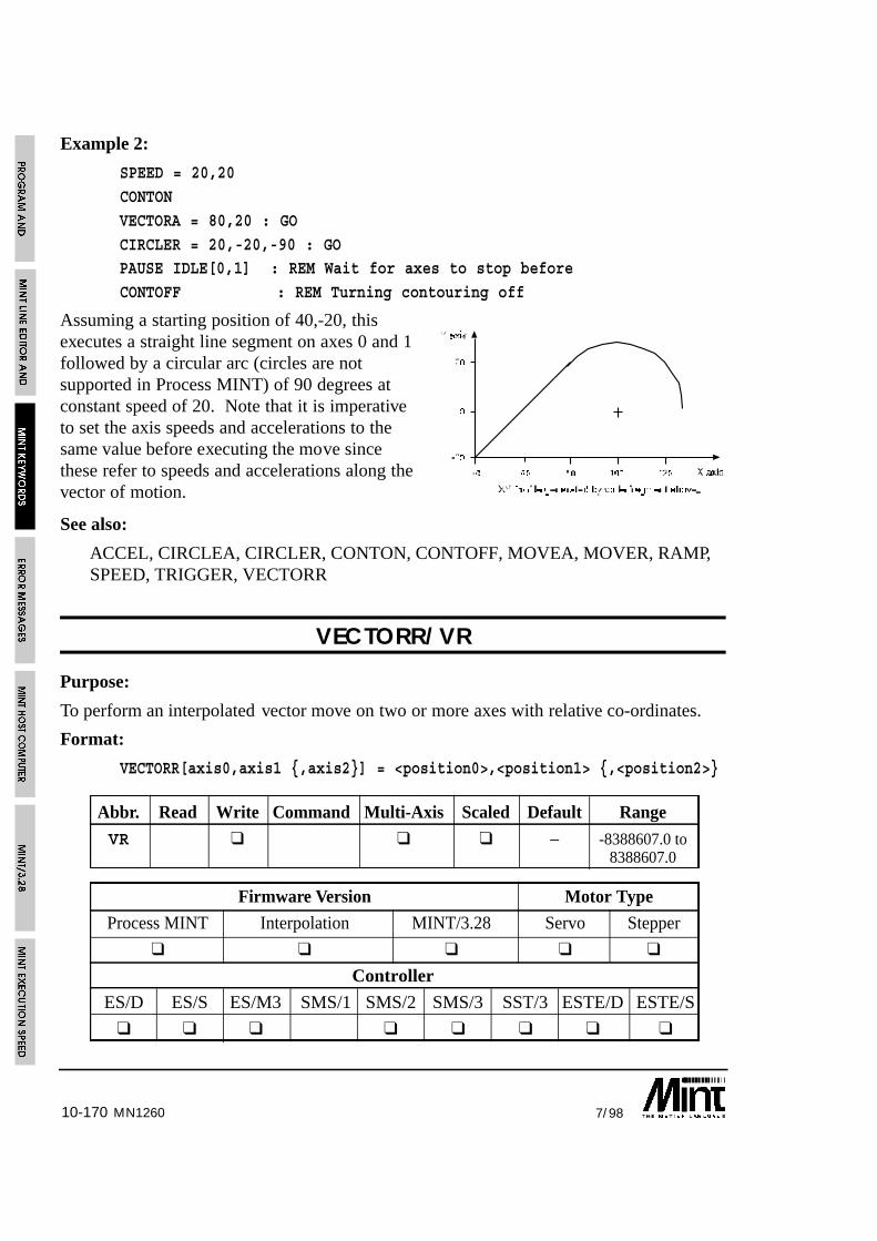
10-170 7/98MN1260
Example 2:
SPEED = 20,20
CONTON
VECTORA = 80,20 : GO
CIRCLER = 20,-20,-90 : GOPAUSE IDLE[0,1] : REM Wait for axes to stop before
CONTOFF : REM Turning contouring off
Assuming a starting position of 40,-20, thisexecutes a straight line segment on axes 0 and 1followed by a circular arc (circles are notsupported in Process MINT) of 90 degrees atconstant speed of 20. Note that it is imperativeto set the axis speeds and accelerations to thesame value before executing the move sincethese refer to speeds and accelerations along thevector of motion.
See also:
ACCEL, CIRCLEA, CIRCLER, CONTON, CONTOFF, MOVEA, MOVER, RAMP,SPEED, TRIGGER, VECTORR
VECTORR/VR
Purpose:
To perform an interpolated vector move on two or more axes with relative co-ordinates.
Format:
VECTORR[axis0,axis1 {,axis2}] = <position0>,<position1> {,<position2>}
Abbr. Read Write Command Multi-Axis Scaled Default Range
VR ❑ ❑ ❑ – -8388607.0 to8388607.0
Firmware Version Motor Type
Process MINT Interpolation MINT/3.28 Servo Stepper
❑ ❑ ❑ ❑ ❑
Controller
ES/D ES/S ES/M3 SMS/1 SMS/2 SMS/3 SST/3 ESTE/D ESTE/S
❑ ❑ ❑ ❑ ❑ ❑ ❑ ❑

10-1717/98
Relative vector move: Two/three axis linear interpolated move on two/three orthogonalaxes specified in relative co-ordinates. At least two axes must be specified. In this modethe axis speed, acceleration and ramp apply not to the individual axis but to the vectoralong which movement occurs. The command will be accepted during a current positionalmove but will not be executed until the next GO statement.
Although vector moves can be mixed between stepper and servo motors, it is desirablethat the step count on the stepper is the same as the encoder count on the servo.
The desired end position of the vector move can be read using either theMOVEA or MOVER keywords.
Example:
VECTORA[1,2] = 100,100 : GOVECTORR[1,2] = 100,200 : GO
? MA[1];MA[2];
will display:
200 300
Example 2:
SPEED = 20,20
CONTON
VECTORR = 40,40 : GOCIRCLEA = 100,0,-90 : GO
PAUSE IDLE[0,1] : REM Wait for axes to stop before
CONTOFF : REM Turning contouring off
Assuming a starting position of 40,-20, this executes a straight line segment on axes 0 and1 followed by a circular arc (circles are not supported in Process MINT) of 90 degrees atconstant speed of 20. Note that it is imperative to set the axis speeds and accelerations tothe same value before executing the move since these refer to speeds and accelerationsalong the vector of motion.
See also:
ACCEL, CIRCLEA, CIRCLER, CONTON, CONTOFF, MOVEA, MOVER, RAMP,SPEED, TRIGGER, VECTORA
MN1260

10-172 7/98MN1260
VEL/VL
Purpose:
To return the instantaneous axis velocity.
Format:
v = VEL[axis]
Abbr. Read Write Command Multi-Axis Scaled Default Range
VL ❑ ❑ ❑ ❑ 0 0 to 32000
Firmware Version Motor Type
Process MINT Interpolation MINT/3.28 Servo Stepper
❑ ❑ ❑ ❑ ❑
Controller
ES/D ES/S ES/M3 SMS/1 SMS/2 SMS/3 SST/3 ESTE/D ESTE/S
❑ ❑ ❑ ❑ ❑ ❑ ❑ ❑ ❑
Returns instantaneous axis velocity in counts/second where the sign indicates direction.VEL is applicable in all modes of motion. For a scale factor of 1, the minimum resolutionof VEL is 500 for a LOOPTIME of 2 and 1000 for a LOOPTIME of 1.
VEL is dependent on the scale factor (SCALE) on read back only.
Using the AUX keyword, the velocity can be directed to a DAC output to assist withsystem tuning using an oscilloscope.
Writing to VEL sets the IDLE velocity. This is the velocity where MINT thinks the motoris at rest. VEL is defined in quadrature counter per servo cycle and is defaulted to zero.A value other than zero should be set if the motor suffers a lot of ‘jitter’ which may resultin it never settling to zero velocity.
Example:
VEL = 1 : REM 1 quad count/per servo loop = 500 counts/sec
MOVEA = 100 : GO
PAUSE IDLE
See the IDLE keyword for further details.
See also:
AUX, JOG, LOOPTIME. PRESCALE, PULSEVEL, SPEED
10-1737/98 MN1260
VER
Purpose:
To display the current MINT version number.
Format:
VER
Display the version number of the MINT software.
The version number of the software should be quoted in all correspondence,with your distributor, regarding queries with MINT.
VN
Purpose:
To return the firmware version number in a MINT/3.28 data packet
Abbr. Read Write Command Multi-Axis Scaled Default Range
VN ❑ – –
Firmware Version Motor Type
Process MINT Interpolation MINT/3.28 Servo Stepper
❑ ❑ ❑
Controller
ES/D ES/S ES/M3 SMS/1 SMS/2 SMS/3 SST/3 ESTE/D ESTE/S
❑ ❑ ❑ ❑ ❑ ❑ ❑ ❑ ❑
The VN keyword returns the MINT/3.28 firmware version number in the data field of aMINT/3.28 data packet. Note that the data returned is a string containing alpha-numericcharacters.
10-174 7/98MN1260
WAIT/WT
Purpose:
To halt program execution for a given number of milli-seconds.
Format:
WAIT = <expr>
Abbr. Read Write Command Multi-Axis Scaled Default Range
WT ❑ – 2 to 65535
Firmware Version Motor Type
Process MINT Interpolation MINT/3.28 Servo Stepper
❑ ❑ ❑ ❑
Controller
ES/D ES/S ES/M3 SMS/1 SMS/2 SMS/3 SST/3 ESTE/D ESTE/S
❑ ❑ ❑ ❑ ❑ ❑ ❑ ❑ ❑
Program execution is suspended for the number of milliseconds specified by <expr>.WAIT can be interrupted by a MINT interrupt.
Example:
OUT1 = _on : REM Turn output on
WAIT = 250 : REM Wait 1/4 second
OUT1 = _off : REM Turn output off
will turn output 1 on which may be activating a solenoid, wait 1/4 second for the solenoidto settle, then turn if off.
See also:
TIME

10-1757/98
WHILE .. ENDW
Purpose:
To perform a loop while a condition is true.
Format:
WHILE <condition>
{statements}ENDW
A WHILE will loop until the <condition> after the WHILE becomes false. Unlike aREPEAT loop which will execute at least once, a WHILE loop will only execute if the<condition> is true. A WHILE loop must be terminated with an ENDW (end while).
Example:
WHILE _true
{statements}
ENDW
while loops are useful for looping indefinitely (see also LOOP), for instance:
WHILE !IN7
JOG = INENDW
loops round until input 7 is set, reading the digital inputs and jogging the motor at a speedset by the binary value of these inputs.
WHILE loops may be nested up to 10 levels.
EXIT can be used to prematurely terminate the loop.
See also:
EXIT, FOR..NEXT, LOOP..ENDL, PAUSE, REPEAT..UNTIL
MN1260
10-176 7/98MN1260
WRAP/WR
Purpose:
To instruct MINT when the external (pulse follower) timer is reset.
Format:
WRAP = <expression>
v = WRAP
Abbr. Read Write Command Multi-Axis Scaled Default Range
WR ❑ ❑ 0 0 to 32767
Firmware Version Motor Type
Process MINT Interpolation MINT/3.28 Servo Stepper
❑ ❑ ❑ ❑ ❑
Controller
ES/D ES/S ES/M3 SMS/1 SMS/2 SMS/3 SST/3 ESTE/D ESTE/S
❑ ❑ ❑ ❑ ❑ ❑ ❑ ❑ ❑
In pulse following mode, if an index pulse, from a master encoder, is used to reset thetimer input, the number of pulses per turn must be set by the WRAP keyword. Thisensures that MINT can take into account the timer being reset. Assigning a value of 0 willdisable the wrap feature.
Example:
WRAP = 2000will inform MINT that the timer input is reset every 2000 counts.
See also:
OFFSET, PULSE, TIMER

10-1777/98 MN1260
22Not standard. Cannot be used in conjunction with the 3rd Axis Servo Board (ES/06)
XENCODER/XE
Purpose:
To read back the position of the encoder on the three channel encoder interface board.
Format:
XENCODER[axes] = <expr> {,<expr> ...}
v = XENCODER[axis]
Abbr. Read Write Command Multi-Axis Scaled Default Range
XE ❑ ❑ ❑ – -8388607 to8388607
Firmware Version Motor Type
Process MINT Interpolation MINT/3.28 Servo Stepper
❑ ❑ ❑ ❑ ❑
Controller
ES/D ES/S ES/M3 SMS/1 SMS/2 SMS/3 SMM/1 SMM/2 SMM/3 SST/3 ESTE/D ESTE/S
❑22 ❑ ❑ ❑ ❑ ❑ ❑ ❑ ❑22 ❑
The operating firmware for the 3 channel encoder interface board is supported as standardwith esMINT v2.65 and above (denoted by /X on the version number) on most controllers.In order to use the XENCODER keyword, the 3 channel encoder board must be switchedon using the AXISCON keyword as follows:
AXISCON.1 = AXISCON.1 | 010
This will turn on the external encoder for axis 1. Note the use of a binary number andbitwise OR to retain bit settings on AXISCON.
The use of the XENCODER keyword has been further enhanced as follows:
The XENCODER value can be written to. This allows the 3 channel encoderinterface board to be used for positional verification on a stepper system.
The 3 channel encoder board can be used to provide a master reference to camprofiles, flying shears and software gearboxes. The source of the master input is givenusing the FOLLOWAXIS keyword:

10-178 7/98MN1260
FOLLOWAXIS Source
-2 Follow the pulse timer input. Now applies to the FOLLOWkeyword
-1 Follow a constant base speed set by the SPEED keyword
0 Follow axis 0
1 Follow axis 1
2 Follow axis 2
3 Follow external encoder channel 0
4 Follow external encoder channel 1
5 Follow external encoder channel 2
Notes:
SmartSystem/1 and SmartMove/1 do not support the three channel encoder board.Instead, use the additional master encoder input provided with the controller. This isread using POS.1.
EuroSystem does not support the three channel encoder board as standard. Supportcan be supplied by on request if the 3rd axis servo board (ES/O6) is not required.
The velocity of the encoder channel cannot be read.
The XENCODER position is not latched during a fast interrupt.
The value is returned in quadrature counts and is not scaled by the SCALE keyword.
Example:
The 3 channel encoder board is used as a position reference for an open loop steppersystem. Assume a 1:1 relationship between the step rate and encoder counts.
MOVEA = 100 : GO[0]
PAUSE IDLE
finalPos = POS
WHILE POS <> XENCODERMOVER = finalPos = XENCODER : GO
PAUSE IDLE
ENDW
See also:
AXISCON, CAM, CAMA, ENCODER, FLY, FOLLOW, FOLLOWAXIS, POS

10-1797/98 MN1260
23The axis number references the I/O bank
XIO/XIXIO0..7
For use with 24 bit expanded I/O option board only
Purpose:
To read and write to the 24 bit expanded I/O option board.
Format:
XIO[bank] = <expression> {,<expression> ...}
v = XIO[bank]
Abbr. Read Write Command Multi-Axis Scaled Default Range
XI ❑ ❑ ❑ 23 – 0 to 255XX 0 to 1
Firmware Version Motor Type
Process MINT Interpolation MINT/3.28 Servo Stepper
❑ ❑ ❑ ❑ ❑
Controller
ES/D ES/S ES/M3 SMS/1 SMS/2 SMS/3 SST/3 ESTE/D ESTE/S
❑ ❑ ❑ ❑ ❑ ❑ ❑ ❑ ❑
24bit I/O keywords feature as standard in MINT for use with the 24 bit I/O option board.The 24 bits of I/O are treated as 3 banks of 8 and are accessed through the XIO keyword(standing for eXpanded I/O). Each bank is on an individual axis. For example:
XIO.1 = 1: REM Output to bank 1 (bit 8)
? XIO.2 : REM Read inputs on Bank 2
X2.0 = 0 : REM Clear bit 2 of bank 0
Reading XIO will return the input value. Writing to XIO will write out to the outputs.Each individual bit can be addressed by appending the bit number to the XIO keyword.For example XIO2/X2. Note that X2 is the abbreviated keyword for XIO2.

10-180 7/98MN1260
I/O Bit Keyword Bank
0 XIO0[0] 0
1 XIO1[0] 0
2 XIO2[0] 0
3 XIO3[0] 0
4 XIO4[0] 0
5 XIO5[0] 0
6 XIO6[0] 0
7 XIO7[0] 0
8 XIO0[1] 1
9 XIO1[1] 1
10 XIO2[1] 1
11 XIO3[1] 1
12 XIO4[1] 1
13 XIO5[1] 1
14 XIO6[1] 1
15 XIO7[1] 1
16 XIO0[2] 2
17 XIO1[2] 2
18 XIO2[2] 2
19 XIO3[2] 2
20 XIO4[2] 2
21 XIO5[2] 2
22 XIO6[2] 2
23 XIO7[2] 2
SmartMove I/O expansion is via CAN bus
See also:
IN, OUT

10-1817/98 MN1260
24The axis number references the I/O bank
XOUT/XO
For use with 24 bit expanded I/O option board only
Format:
v = XOUT[bank]
Abbr. Read Write Command Multi-Axis Scaled Default Range
XO ❑ ❑ 24 – 0 to 255
Firmware Version Motor Type
Process MINT Interpolation MINT/3.28 Servo Stepper
❑ ❑ ❑ ❑ ❑
Controller
ES/D ES/S ES/M3 SMS/1 SMS/2 SMS/3 SST/3 ESTE/D ESTE/S
❑ ❑ ❑ ❑ ❑ ❑ ❑ ❑ ❑
The expanded output value can now be read back as a byte value. This can be used forsetting outputs without affecting others.
Example:
XIO = XOUT & 011110000
turn expanded output bits 0 to 3 off without affecting bits 4 to 7.
Notes:
There are no keywords for reading back individual bit values.
XOUT cannot be written to. XIO must be used for this function.
SmartMove I/O expansion is via CAN bus
See also:
OUT, XOUT

10-182 7/98MN1260
ZERO/ZR
Purpose:
To set the present axis position to zero.
Format:
ZERO[axes]
Abbr. Read Write Command Multi-Axis Scaled Default Range
ZR ❑ ❑ – –
Firmware Version Motor Type
Process MINT Interpolation MINT/3.28 Servo Stepper
❑ ❑ ❑ ❑ ❑
Controller
ES/D ES/S ES/M3 SMS/1 SMS/2 SMS/3 SST/3 ESTE/D ESTE/S
❑ ❑ ❑ ❑ ❑ ❑ ❑ ❑ ❑
Defines the present axis position to be the zero position.
Example:
MA.2 = 200 : GO.2
PAUSE IDLE.2
ZERO.2
moves to absolute position 200 and resets the position to zero when the axis comes to rest.
To define a new position other than zero, use the POS keyword. For example:
POS.2 = 100
will set a position of 100 units.
See also:
POS, RESET

10-1837/98 MN1260
ZZ
Purpose:
To return the position for all three axes and I/O information in a MINT/3.28 datapacket. .
Format:
ZZ
Abbr. Read Write Command Multi-Axis Scaled Default Range
ZZ ❑ – –
Firmware Version Motor Type
Process MINT Interpolation MINT/3.28 Servo Stepper
❑ ❑ ❑
Controller
ES/D ES/S ES/M3 SMS/1 SMS/2 SMS/3 SST/3 ESTE/D ESTE/S
❑ ❑ ❑ ❑ ❑ ❑ ❑ ❑ ❑
Reading ZZ will return the following keyword values as comma separated.
POS[0], POS[1], POS[2], IDLE[0], IDLE[1], IDLE[2], MP[0], MP[1],MP[2], IN, STOPSW, ANALOGUE1, ANALOGUE2, XIO[0], XIO[1], XIO[2]
as abbreviated or MINT/3.28 keywords, this becomes:
PS[0], PS[1], PS[2], ID[0], ID[1], ID[2], MP[0], MP[2], IN, SS, A1, A2, XI[0],XI[1], XI[2]
Due to the size of the return datapacket, it is important that the read buffer is large enoughto handle the data.
See also:
ANALOGUEx, IDLE, MP, POS, STOPSW, XIO

10-184 7/98MN1260

11-17/98 MN1260
11. Error MessagesAll error messages begin with the syntax:
ERROR:
This may be of use when operating the controller as a slave to a host computer - the hostneed only check for the word ERROR: to detect a card error. The command LASTERRcan be used to display the last error message that caused program termination.
11.1 General Error Messages
Syntax error
Invalid character(s) or syntax has been found on a line.
Example:
GAIN = 12*
A syntax error will also occur if a MINT keyword is used in a DIM statement. Forexample
DIM a1(100)
The variable a1 is the abbreviation for ANALOGUE1
Too many levels of nesting/Stack Overflow
The total level of nesting has exceeded the maximum allowed in MINT. Refer to the tablebelow for the maximum levels of nesting.
MINT Structure Max Nesting Level
IF..DO 30
FOR 8
GOSUB 20
LOOP 10
REPEAT 10
WHILE 10
Combined 30
No expression
There is an assignment but no expression.

11-2 7/98
Example:
avar =
Invalid Command
An unknown command is found. MINT immediately assumes it is a variable, or theprogram has encountered an ENDW or UNTIL statement without a WHILE/REPEAT.
Undefined Variables
A variable has been encountered that has not been declared or a variable has been used asa command. Use the DISPLAY command to list all the currently defined variables.
Too many variables
The total number of variables defined exceeds the total allowed (50 maximum). It may bethat variables have been declared in the immediate (user prompt) mode, that are not usedin the program. Use the RELEASE command to release all currently defined variablesfrom memory or re-define some variables.
Invalid Index
An index has been used in an array variable that is out of range. Example:
DIM a(10)
a(11) = 12 : REM Invalid index#
The index must be in the range of 1 to the maximum number of elements defined.
Out of memory
This can occur for the following reasons:
• There is not enough memory to store the compiled code.
• Too many array variables have been declared given the available memory.
• There is not enough room to insert a line of code into the current buffer.
• If you are using REM statements in your source file, remove some of them and re-execute the program. Alternatively, if arrays have been defined, reduce the number ofarray elements.
Line too long
A line within the program or configuration file exceeds 127 characters in length. Thisapplies to memory expansion and will occur during compilation.
MN1260

11-37/98
No Memory Card
An attempt was made to read or write to the memory card when no memory card exists.LOAD, SAVE and OFFLINE arrays can produce this error message. If the write protectswitch is on, a read or write from an OFFLINE array will produce a “No Memory Card”message.
11.2 Subroutine Errors
Too many labels
Too many subroutines have been defined (40 maximum).
Invalid label
This can occur for the following reasons:
• A duplicate subroutine (label) has been defined. Remember that only the first tencharacters of a name are significant, therefore “subroutine_1” and “subroutine_2” arethe same.
• A subroutine has been called that does not exist. This error will occur at compiletime.
• The label name is neither a number or a valid variable name.
RETURN w/o GOSUB
A RETURN statement has been found when no GOSUB was called.
11.3 Conditional Statement Errors
THEN or DO expected
An IF statement has been entered without a THEN or DO.
ELSE/ENDIF w/o IF DO
An ELSE or ENDIF statement has been found without an IF DO statement.
Example:
IF a = 10WHILE true
<statements>
ELSE <— Error
<statements>ENDIF
MN1260
11-4 7/98
11.4 Loop Structure Errors
TO expected
A FOR loop has been found with no TO.
NEXT w/o FOR
A NEXT has been found without a respective FOR.
ENDW w/o WHILE
An ENDW statement has been found without a respective WHILE.
UNTIL w/o REPEAT
An UNTIL statement has been found without a respective REPEAT.
Incorrect loop terminator
A loop or block structure does not have an associated closing keyword. For example,LOOP was found with no ENDL.
11.5 Motion Variable/Command Errors
Write only
An expression contains a read of a write only variable or command
Example:
a = FLY
Read only or Command
An attempt has been made to write to a read only variable or read/write to a command.Example:
A1 = 10
a = STOP
Missing parameter
A system command declaration is missing an axis in the expression.
Examples:
GAIN[1] = 10,20
VR[0,1] = ,100
In the first example, no axis number has been given for the value 20. In the secondexample, VR (vector move) requires at least 2 parameters.
MN1260

11-57/98
Card Aborted
The card is aborted when a motion keyword is executed. Use RESET or CANCEL toclear the error.
Limit Error
Limit error on axis when a motion keyword is executed. Use RESET or CANCEL toclear the error.
Following Error
Following error on axis when a motion keyword is executed. Use RESET or CANCEL toclear the error.
Invalid mode
The axis has not been set up for the correct motor type when the motion keyword isexecuted. For example:
CONFIG = _stepper
FREQ = 200
This will give an Invalid Mode error since the axis must be set-up as a servo motor beforeyou can write to the frequency generator.
Out of range
A system variable has been assigned a value that is out of its range. Remember that thevalid numerical ranges for SPEEDs, accelerations and positions vary depending on theSCALE keyword.
Motion in progress
An assignment to a motion variable or command was encountered when motion was inprogress. Some motion variables or commands can only be executed when the axis is idleor only when specific modes of motion are being used. See 11 for details of eachkeyword.
Example:
ACCEL = value
JOG = valueare both invalid during a positional move.
MN1260

11-6 7/98
Example 2:
AXES[0,1]
JOG[1] = 1000MOVEA[0] = 10 : GO
results in a motion in progress error since GO will try and begin motion on axes 0 and 1.The following will cure the problem:
AXES[0,1]
JOG[1] = 1000
MOVEA[0] = 10 : GO[0] : REM Explicit axis reference
Servo off
A move was attempted when the servo amplifier had been disabled in software with theSERVOFF command. Execute SERVON or SERVOC to turn servo power on.
Invalid axis
An axis number was specified that was not a variable or number. Array variables orexpressions cannot be used as axis numbers. Vector and circular moves require at least 2axes. An invalid axis error will occur if this is not the case.
Examples:
VR[0] = 100SF[a+1] = 1000
Output Error
Applies only to SmartMove. One or more of the digital outputs has gone into error. Thiscan be result of: over current; over temperature or short circuit. Check the wiring andclear the error using RESET.
MN1260

12-17/98
12. MINT Host Computer CommunicationsIn many applications a MINT program running on the controller performs a local controlfunction, while a supervisory ‘host computer’ controls the overall system. There is usuallya requirement for data interchange with the host computer. MINT protectedcommunications is an enhancement to the MINT language for systems where secure datainterchange is required.
Connection between cards is normally via an RS485 multi-drop serial link. The system isset-up as a master/slave configuration, where the host computer acts as the master and thecontroller cards are the slaves. The host computer can talk to only one slave at any onetime and must ensure that it does not transmit data to another slave before receiving areply from the previous slave, otherwise there may be contention.
The protected communications routines allow interchange of data between host computerand MINT via an array variable COMMS, which is 99 locations in length. The commandCOMMSON is placed at the top of the MINT program to activate protectedcommunications.
The following simple example will jog the motor at a speed defined by comms location 1which is transmitted to the controller from the host. At the same time , the host can readthe position of the moor by reading comms location 2.
MN1260
12-2 7/98
Example:
COMMSON
comms(1) = 0LOOP
JOG.0 = comms(1)
comms(2) = POS.0
ENDL
The protocol is based on ANSI x3.28 with minor modifications.
The end of the section gives details of some library routines for the IBM PC written inTurbo C and QBasic as supplied with MS-DOS 5.0. The routines can be found on theaccompanying diskette in the ‘comms’ directory. Alternatively, the MINT InterfaceLibrary can be purchased which provides the necessary Windows libraries for 3.1, 95 andNT, compatible with most of the common programming development tools.
12.1 Activating Protected CommunicationsThe protected protocol is activated by placing the COMMSON keyword at the top of theprogram file. This instructs MINT that all incoming data is used to make up datapackets,and as such Ctrl-E will be ignored. The communications protocol can be aborted bysending a special data packet. Ctrl-E can then be used to abort program execution.
COMMSON must be placed before any other DIM statement since it automaticallydefines the array, COMMS which is used for data transfer.
Example:
COMMSONDIM a(100)
DIM b(100)
is valid, however:
DIM a(100)DIM b(100)
COMMSON
is invalid. The array variable a, will share the same data area as the array variableCOMMS.
Ideally, COMMSON should be placed in the configuration file just after the AUTOkeyword. This reduces the chance of data packets resulting in program termination whenthe controller is powering up.
MN1260

12-37/98
Once COMMSON has been issued, MINT will now be ready to receive and process datapackets. The data packet structures are described in the following sections.
The COMMSOFF keyword is used to turn protected communications off and can be usedin conjunction with COMMSON to turn protected communications on and off. OnceCOMMSON has been used once to define the comms array, any further use will turn thecommunication protocol on.
12.2 Use of the COMMS variableCOMMS looks like an array variable of dimension 99. COMMS differs from the normalMINT array variables in that there is no need to define it with a DIM statement since it isautomatically defined with the COMMSON keyword. The contents of the COMMS arrayare preserved during power off.
Use of COMMS is very simple. For instance, consider the following wire windingapplication, where a drum is traversed between two points defined by a host computer:
COMMSONcomms(3) = 0 : REM Initialize the value first
LOOP
IF POS>COMMS(2) THEN PULSE = -COMMS(3)
IF POS<COMMS(1) THEN PULSE = COMMS(3)COMMS(4) = POS
ENDL
The program is a simple continuous loop. The drum will be driven back at forth betweenpoint specified by COMMS(2) and COMMS(1) at a speed proportional to the rotation ofthe drum (measured using an encoder on the drum). The following ratio is specified bythe variable COMMS(3). These values can be changed at any time by sending datapackets from the host computer and are automatically made available to the MINTprogram.
MN1260

12-4 7/98
Example 2:
COMMSON
comms(1) = 0LOOP
command = comms(1)
IF command <> 0 DO
IF command = 1 THEN SP.1 = comms(2):MOVEA.1 = comms(3):GO.1:PAUSE IDLE.1
IF command = 2 THEN SP.1 = comms(2):MOVER.1 = comms(3):GO.1:PAUSE IDLE.1IF command = 3 THEN HM.1 = comms(4):PAUSE IDLE.1
ENDIF
comms(1) = 0 : REM Send Ack back to host
ENDL
In this example, the host will transmit a command in comms(1). The data for the movetype is held in indexes 2 to 4. When the moves is complete, the command is set to zero.This acts as an acknowledgement to the host.
Similarly, the host can read the position of the drum by reading the value of COMMS(4),which is updated once per loop (approximately every 10mS). The communicationsroutines ensure that valid data is available to both MINT and host computer.
12.3 Read and Writing Data from a HostIn order to read from a location on a controller or write to a location, a datapacket is sentfrom the host. This is made up of ASCII characters, including control characters. In orderto send a number, this is transmitted as a string, for example “1234.5”. All controlcharacters are shown in the shaded boxes.
MN1260

MN1260 12-57/98
12.3.1 Writing Data
The host sends the following data packet to write information to the card.
Reset: EOT (04H)
Card ID: ASCII character 0-9;A-F; set by axis switch on card
Card ID: Card ID repeated
Start: STX (02H)
Comms address digit 1: ASCII character 0-9; location in COMMS arrayM.S. digit
Comms address digit 2: ASCII character 0-9; location in COMMS arrayL.S. digit
Data field: Up to 60 characters, decimal format, commaseparated, for example: ì1234,45.6,-23.4î
End: ETX (03H)
Checksum: 1 byte, XOR of everything after (but not including)STX, up to and including ETX
Note: M.S.: most significant; L.S.: least significant
Note that the card ID and the comms address are both ASCII values. To write to commsaddress 12, the user would send the ASCII character 1, followed by the ASCII character 2.
The card will respond with an ACK (06H) or a NAK (015H), within 50mS of receipt ofchecksum. A NAK will be sent if the data field contains an invalid string, or thechecksum is incorrect. The card ID is set by the 4 way address switch on the card.
The data may be comma separated where each data value will load into subsequentcomms addresses. For example, if the data string “10,20,30” is sent to comms address 10,address 10 will contain 10, address 11 will contain 20 and address 12 will contain 30.Note that the total data length field must not exceed 60 characters.

12-6 7/98
12.3.2 Reading Data
The host sends the following data packet to read data:
Reset: EOT (04H)
Card ID: ASCII character 0-9;A-F; set by axis switch on card
Card ID: Card ID repeated
Start: STX (02H)
Comms address digit 1: ASCII character 0-9; location in COMMS array M.S. digit
Comms address digit 2: ASCII character 0-9; location in COMMS array L.S. digit
End: ENQ (05H)
The card will reply with the following data packet:
Start: STX (02H)
Comms address digit 1: 0-9; location in COMMS array M.S. digit
Comms address digit 2: 0-9; location in COMMS array L.S. digit
Data field: Up to 60 characters, decimal format
End: ETX (03H)
Checksum: 1 byte, XOR of everything after (but not including) STX,up to and including ETX
The reply will be sent within 50mS of receipt of the checksum. A NAK will be sent if thecomms address is invalid.
12.3.3 Special Location
Communication address 00, is used for special purposes. Writing to location 00 willenable the host to abort program execution. Reading location 00 will return an errorstatus.
MN1260

12-77/98 MN1260
12.3.3.1 Aborting Program Execution
The abort character (Ctrl-E) is used in the protocol and could appear at any time during achecksum. Therefore, when COMMSON is executed, Ctrl-E will not be active in thenormal sense.
To abort the program, first send a null data field to special communications location 00:
Reset: EOT (04H)
Card ID: ASCII character 0-9;A-F; set by axis switch on card
Card ID: Card ID repeated
Start: STX (02H)
Comms address digit 1: ASCII character 0
Comms address digit 2: ASCII character 0
End: ETX (03H)
Checksum: 1 byte, XOR of everything after (but not including) STX,up to and including ETX
The controller will revert to normal non-protected mode, so that Ctrl-E will cause anabort. COMMSOFF can also be used to revert back to the non-protected mode.
The checksum for the null data packet is ETX.
cTERM for DOS can be used to automatically send the data packet bypressing Shift-F8 and selecting the required card.
12.3.3.2 Program Status
To allow the host to detect an error on the slave controller, reading location 00 will returnthe status of the error and whether the controller is stepper or a servo controller. Thecontroller will return the following data packet:
Start: STX (02H)
Error 0; No Error, 1; Error
Controller Type 0; Servo, 1; Stepper
End: ETX (03H)
Checksum: 1 byte, XOR of everything after (but not including) STX,up to and including ETX
The controller type byte can also be used to detect whether the card is up and running ornot.
12-8 7/98
12.4 Limitations of UseINKEY and INPUT should not be used when MINT is in protected communications modesince they will take bytes from the incoming data packet, corrupting it, unless TERM isused it direction all terminal I/O to the LCD keypad and display.
12.5 PC Library RoutinesSample source code is provided with the installation disk for integration into Capplications. Alternatively, the MINT Interface Library can be purchased which providesthe necessary Windows libraries for 3.1, 95 and NT, compatible with most of the commonprogramming development tools.
Using the Host Computer Communications facility in MINT (COMMSON keyword), ahost computer can communicate with MINT over the serial port, using a protectedprotocol. Two example programs are given, one written in ‘C’ and the other written inQBasic as supplied with MS-DOS 5.0. These provide two functions which allow you tosend and receive data to and from the controller. Both programs are available on theaccompanying Applications and Utilities diskette in the following files
COMMSON.C: C Routines found in CLIB sib-directory
COMMSON.BAS QBasic Routines found in BASICLIB sub-directory
Although MINT does not support floating point numbers as such, instead using scaledintegers, floats are used within the example programs. Care must be taken that thefloating point numbers are not converted to exponent form for transmission.
12.5.1 C Interface
The C source provides the necessary routines to read and write data with the followingfeatures:
• Retry a maximum of 5 times
• Re-transmit on a checksum error
• Floating point numbers as the default data type
A serial port interface, written in Borland Turbo C, can be found on the enclosedapplications diskette in the CLIB directory. The following functions are used in theCOMMS routines to access the serial port buffer:
void flushSerialPort( void )
Flush serial port or serial port buffer
int getCharacterFromSerialPort( void )
MN1260

12-97/98
Read the next character from the serial port or serial port buffer in the range of 0 to 255.It is assumed that a time-out feature has been built into the function and the function willreturn -1 if timed out.
void serialCharacterOutput( int )
Transmit a character over the serial port.
12.5.1.1 Reading and Writing Data
Data is written to the controller through the function commsWrite, which has thefollowing prototype:
int commsWrite( int card, int index, double value );
The parameters are:
card Card address 0 to 15
index Index of comms address, 0 to 99
value Value to be written
The function will return one of the following values:
0 Time-out
1 Transmitted OK
Example:
returnValue = commsWrite( 0, 10, 10.5 )
Write 10.5 to index 10 on card 0, ie. COMMS(10) = 10.5
Data is read from the controller using the function commsRead, which has the followingprototype:
int commsRead( int card, int index, double *value );
The parameters are:
card Card address 0 to 15
index Index of comms address, 0 to 99
value Value, passed by reference, that is read
MN1260

12-10 7/98
The function will return one of the following values:
0 Time-out1 Transmitted OK
Example:
returnValue = commsRead( 1, 2, &value );
Read COMMS(2) from card 1.
The source code can be found on the enclosed applications diskette in the COMMSONdirectory.
12.5.2 MS-DOS 5.0 QBasic Interface
The Basic interface has been written using QBasic as supplied with MS-DOS 5.0. Itshould be possible to convert the program for other types of structured Basic. Theroutines have the following features:
• Retry a maximum of 5 times
• Re-transmit on a checksum error
• Interrupt driven serial port
• Addresses card 0 only, although addressing other cards is an easy amendment to thesoftware
12.5.2.1 Reading and Writing Data
Data is written to the controller using the writeData function which accepts the followingparameters:
letterBox Index of comms array, 0 to 99, to write
dataValue Value to be written
The function will return one of the following values:
0 Time-out
1 Transmitted OK
Example:
returnValue = writeData( 10, 200 )
Write 200 to COMMS(10).
MN1260

12-117/98
Data is read from the controller using the readData function which accepts the followingparameter:
letterBox Index of comms array, 0 to 99, to read
The value read from the controller is passed to the global variable dataValueReturned.
The function will return one of the following values:
0 Time-out
1 Transmitted OK
Example:
returnValue = readData( 1 )
Read comms address 1 ( COMMS(1) ).
An example of use is included in the main body of the program.
MN1260

12-12 7/98MN1260
13-17/98
13. MINT/3.28
MINT/3.28 is an ASCII based protected protocol derived from ANSI x3.28, implementinga subset of the Interpolation command set. MINT/3.28 can be used in place of MINT onstandard controller cards. It is suitable as a slave motion control system, where the slaveresponds to immediate commands from a host computer. The slave cannot execute itsown program.
The communication protocol caters for the 3 motion instruction types that MINT uses.These are:
• Write to a motion variable
• Read a motion variable
• Issue a command
All MINT keywords are limited to their two letter abbreviation. See section 13.9 for acomplete list of MINT motion keywords that are supported.
The system is set-up as a master/slave configuration, where the host computer acts as themaster, and the controller cards are the slaves. The slaves will tri-state their outputdrivers (RS485) unless they are requested to transmit information to the host computer.This implies that the host computer can talk to only one slave at any one time. It istherefore up to the master to ensure that it does not transmit data to another slave beforereceiving a reply from the previous slave, otherwise there may be contention on the line.
‘C’ library routines, for use on a PC, have been provided and can be found on theaccompanying Applications and Utilities diskette in the MINT328 directory. These shouldprovide an adequate interface to MINT/3.28.
13.1 Serial Port ConfigurationThe serial port is configured for:
• 9600 Baud
• 8 data bits
• no parity
• 1 stop bit
A typical system consists of a number of controller cards communicating with a hostcomputer over a multi-drop full duplex RS485 link, in a master/slave arrangement. RS232may also be used where there is only one slave card.
MN1260

13-2 7/98MN1260
13.2 Data Packet StructureFor each instruction, the host transmits a data packet made up of the following elements:
Reset: EOT (04H) Start of Header
Drive ID: Card number followed by the axis number, each digit repeated.
Start: STX (02H) Start of data. Used for Write
MINT Keyword: 2 letter abbreviated keyword.
Data: Data where applicable
End ETX (03H) End of data packet
Checksum: byte checksum.
All control characters are shown in the shaded boxes. Each instruction type data packet isexplained in more detail in the following sections.
13.2.1 Reset: EOT
The reset byte, EOT, instructs the slave of incoming data and to discard any data that maybe in its buffer, should it have received an incomplete data packet.
13.2.2 Drive ID
The Drive ID corresponds to the Card Address (0 to 9; A to F) as the first digit (repeated),followed by the Axis Number (repeated). The Axis Number is interpreted as follows:
Axis Number Axis
0 X
1 Y
2 Z
3 X & Y
4 X & Z
5 Y & Z
6 X, Y & Z

13-37/98 MN1260
To send data to the Y axis on card 2, the following would be sent:
Byte ASCII Value (in HEX) Description
2 32 Card Address
2 32 Card Address
1 31 Axis Number
1 31 Axis Number
13.2.3 MINT Keyword
The MINT keyword is transmitted in its abbreviated form i.e. two letter. A complete listof the MINT keywords supported is shown in section 13.9. The keywords can be in eitherupper or lower case.
13.2.4 Data
A data field will only be sent for write instructions (see section 13.4: Writing Data). Thedata field is represented in its ASCII format. For example, 100.5 would be representedby:
Character ASCII Value
1 31
0 30
0 30
. 2E
5 35
The data field can contain any number within the bounds of MINT scaled integers. Themaximum number of characters for a number will therefore be 12 and would correspondto the number -8388607.996. Note that the maximum size of the number will changedepending upon the scale factor set. If for example the scale factor (SF keyword) is set to500, the number of characters will be 9 (corresponds to: -16777.996).

13-4 7/98MN1260
For data fields which contain more than one number (for instance vector motion) thestring of numbers must be separated by commas. For example, the data field for a vectormove of 10,20, would be represented by:
Character ASCII Value
1 31
0 30
, 2C
2 32
0 30
13.2.5 End of Data: ETX, ENQ
Each data packet is terminated by a single byte. These are:
Byte Instruction
ETX (03H) Write
ENQ (05H) Read
ETX (03H) Command
The ASCII hex value is shown in brackets.
13.2.6 Checksum
A checksum is appended to the end of the data packet for a write and commandinstruction only. The checksum is the exclusive OR of all the bytes received between theMINT keyword and the terminating byte, inclusive. The checksum will ensure that alldata received by the slave is not corrupted.

13-57/98 MN1260
13.3 Slave ReplyWhen the slave receives the data, it will transmit, in the case of a command or writeinstruction, an ACK (06H). For a read instruction, data is transmitted to the master. If forany reason an error occurs, a NAK (15H) will be transmitted. An error can be any one ofthe following conditions:
13.3.1 MINT/3.28 Error Codes
Error Code Error
1 User Abort on slave
2 Maximum following error exceeded
3 Limit switch error
4 Variable value out of range
5 Unknown Command
6 Motion already in progress
7 Servo power is off
8 Communication or checksum error
9 Invalid axis number given
10 Reserved
11 External error
12 Invalid parameters
The error can be interrogated by reading back the error code through the keyword ER.Note that errors 1 to 3 and 11 are fatal errors and must be cleared through use of the resetcommand, RE, or the cancel command, CN. If there is no error, ER will return 0.
The slave will send its reply within 30ms of receipt of the data packet from the master. Ifthe master does not receive a reply, it must assume a NAK.

13-6 7/98MN1260
13.4 Writing DataThe master sends the following data packet to the slave:
Reset: EOT (04H)
Drive ID: Card number followed by the axis number, each digitrepeated. (see below)
Start: STX (02H)
MINT keyword: 2 letter abbreviated MINT keyword.Upper or lower case.
Data Field: Up to 60 characters
End: ETX (03H)
Checksum: byte representing the exclusive OR of all the bytesbetween the MINT keyword and ETX inclusive.
The slave will reply with either an ACK or a NAK, within 30ms of receipt of thechecksum. If the master does not receive a reply, it must assume a NAK. A NAK will besent for any of the error codes 1,2,3,4,5,6,7,8,9,11 (see section 13.3.1)
13.5 Reading DataWhen requesting data from the slave, the master sends the following data packet:
Reset: EOT (04H)
Drive ID: Card number followed by the axis number, each digitrepeated.
Start: STX (02H)
MINT keyword: 2 letter abbreviation
Data: Data where applicable
End: ENQ (05H)

13-77/98 MN1260
The slave will reply with the data packet:
Start: STX (02H)
MINT keyword: 2 letter abbreviation, always in lower case.
Data Field: Up to 60 characters
End: ETX (03H)
Checksum byte representing the exclusive OR of all the bytesbetween the MINT keyword and ETX inclusive.
The reply will be sent within 10 milliseconds of receipt of the ENQ byte. A NAK will besent if the MINT keyword cannot be understood (error code 5), ie it is corrupted. If noreply is received, a NAK must be assumed.
The data field for a read instruction is used to cope with the keyword PEEK/PK. As wellas sending the keyword, the address of the option slot must also be sent. The controllerwill reply with the contents of the address. The data field is also used for formatting thereturn data. By default, if a read datapacket requests the data from more than one axis, thevalues are bitwise-ANDed together. The following characters can be used in the data fieldwhich affect the formatting of the return data:
Code Formatting
| (vertical bar) The results are bitwise-ORed together
, (comma) The results are comma separated
13.6 CommandsCommand data packets are the same as write data packets, but with no data. The masterwill therefore issue the following data packet for a command:
Reset: EOT (01H)
Drive ID: Card number followed by the axis number, each digitrepeated
Start: STX (02H)
MINT keyword: 2 letter abbreviation
End: ETX (03H)
Checksum: byte representing the exclusive OR of all the bytes betweenthe MINT keyword and EOT, inclusive.
13-8 7/98
The slave will reply with either an ACK or a NAK. The reply will be sent within 10milliseconds of receipt of the checksum. A NAK will be sent for the error codes1,2,3,5,6,7,8,9,11 (see section 13.3.1).
13.7 Buffered Motion CommandsMINT/3.28 will accept and set-up the next motion command when a move is in progress.This is particularly useful for contouring, or where two moves must be executed in rapidsuccession. For example:
VR 10,20
VR 12,21
Any further move instructions cannot be accepted until the first move to position 10,20 iscompleted. If any move instruction is received, the slave will reply with a NAK. Readingthe error keyword will return the error code for “motion in progress”.
During contoured motion, it is important to ensure that the next move is always in theslave’s buffer. Therefore the host must periodically check the move pending flag (MP)and immediately send the next move when it is cleared.
It is however acceptable to communicate with the slave while contoured moves are inprogress. A typical function is interrogating position to update an operator display.
13.7.1 The GO Command
The GO command is not required when a move is setup since this will be handledautomatically. When the previous move is complete, the new move will be executed.
MN1260
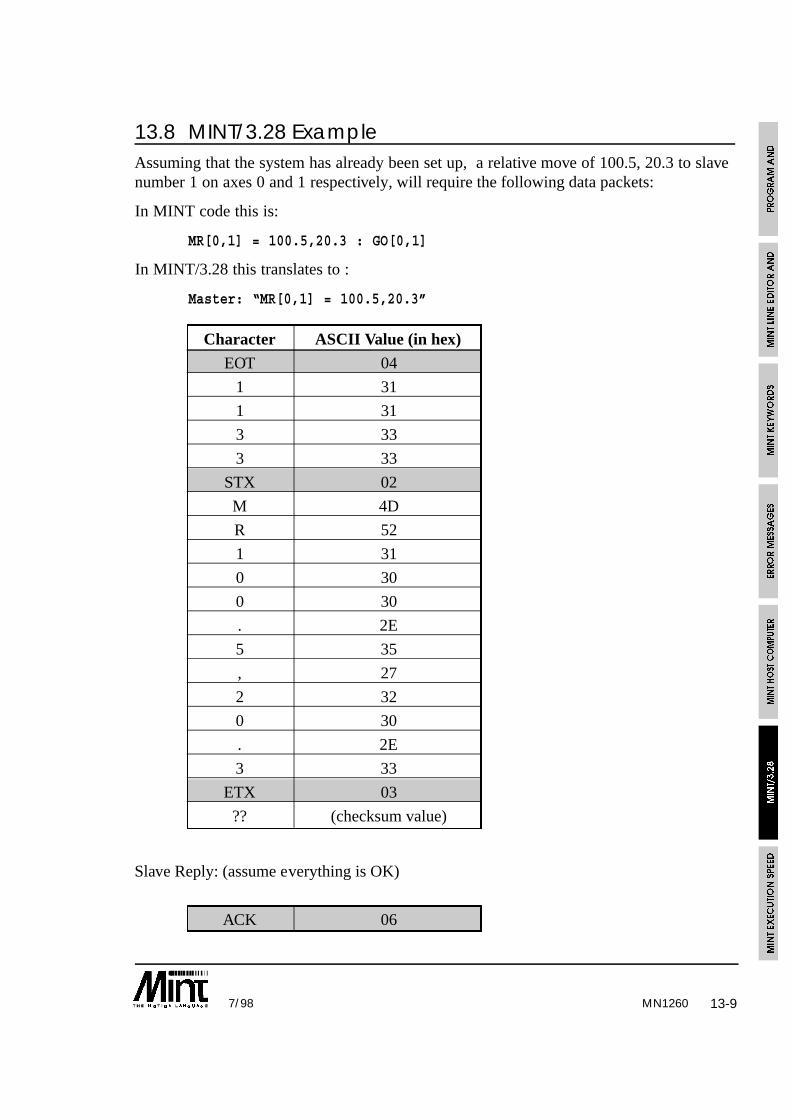
13-97/98 MN1260
13.8 MINT/3.28 ExampleAssuming that the system has already been set up, a relative move of 100.5, 20.3 to slavenumber 1 on axes 0 and 1 respectively, will require the following data packets:
In MINT code this is:
MR[0,1] = 100.5,20.3 : GO[0,1]
In MINT/3.28 this translates to :
Master: “MR[0,1] = 100.5,20.3”
Character ASCII Value (in hex)
EOT 04
1 31
1 31
3 33
3 33
STX 02
M 4D
R 52
1 31
0 30
0 30
. 2E
5 35
, 27
2 32
0 30
. 2E
3 33
ETX 03
?? (checksum value)
Slave Reply: (assume everything is OK)
ACK 06

MN126013-10 7/98
A1 Analog input 1 IR Move increment relativeA2 Analog input 2 JG Speed controlA3 Analog input 3 KF Velocity feedforward gainAB Abort KI Integral gainAC Acceleration KR Integral gain rangeAD Auxiliary DAC KV Velocity feedback gainAT Acceleration Time LM Limit statusAX Tuning output control LT Servo loop timeBA Home backoff MA Move absoluteBF Boost output off MD Mode of motion statusBO Boost output on MF Maximum following errorCA Circle absolute MP Pending mode of motion statusCD Card address MR Move relativeCF Configure axis OF Offset on software gearboxCL Current Limit OT Digital outputsCN Cancel Ox Digital outputsCO Contouring on PK Peek option board locationCR Circle Relative PO Poke option board locationCT Contouring off PS Axis positionDC DAC output PU Software gearbox on external timerDF Set parameters to default PV Pulse velocityDL Disable limits RE ResetDM Demand output level SC Servo on to current positionEB Enable output control SF Scale factorEI Error input status SO Servo offEL Enable Limits SP SpeedEN Encoder value SS Stop input problemER Error status ST Stop motionEW Encoder wrap SV Servo on to previous positionFA Axis to follow TI Timer input valueFE Following error TQ Torque controlFL Encoder following ratio VA Vector absoluteFQ Frequency output control VL Velocity feedbackGN Proportional Gain VN Firmware version numberHM Home control/input status VR Vector relativeHS Home speed WR Timer wrap valueIA Move increment absolute XI Expanded I/OID Idle status Xx Expanded I/OIN Digital inputs ZR Zero positionIx Digital inputs ZZ Status information
13.9 MINT/3.28 Supported Keywords

13-117/98
13.10 MINT/3.28 C Library Routine for Host ComputerSample source code is provided with the installation disk for integration into Capplications. Alternatively, the MINT Interface Library can be purchased which providesthe necessary Windows libraries for 3.1, 95 and NT, compatible with most of the commonprogramming development tools.
The sample code gives the following functions:
• Writing to a motion variable
• Reading a motion variable
• Issuing a command
The routines have the following features:
• Retry a maximum of 5 times
• Re-transmit on a checksum error
• Floating point numbers as the default data type
The source code is available on the enclosed applications diskette in the directory CLIB(filename MINT328.c). A serial port interface, written in Borland Turbo C, can be foundon the enclosed applications diskette in the SERIAL directory. The following functionsare used in the MINT/3.28 routines to access the serial port buffer:
int getccb( void )
Read the next character from the serial port or serial port buffer in the range of 0 to 255.If no byte is available, getccb must return -1.
void SerialOut( char )
Transmit a character over the serial port.
13.10.1 Writing Data
A motion variable is written to using the function MINT328Write which has the followingprototype:
int MINT328Write( char *cardAxis, char *keyword, char *dataValue );
The parameters are:
cardAxis Card address 0 to 15, followed by axis
keyword Abbreviated keyword
value Value to be written (string)
MN1260

13-12 7/98
The functions can be easily re-written to accept floating point numbers etc.
The function will return one of the following values:
6 (ACK) OK
21 (NAK) Transmission Problem
-1 Timeout
Example:
returnValue = MINT328Write( “0011”, “SF”, “1000” );
Set the scale factor on card 0, axis 1 to 1000.
13.10.2 Reading Data
A motion variable is read using the MINT328Read function which has the followingprototype:
int MINT328Read( char *cardAxis, char *keyword, long *dataValue );
The parameters are:
cardAxis Card address 0 to 15, followed by axis
keyword Abbreviated keyword
value Value to be read, passed by reference as a long.
The function will return one of the following values:
6 (ACK) OK
21 (NAK) Transmission Problem
-1 Timeout
Example:
returnValue = MINT328Read( “1100”, “PS”, &value );
Read the position of axis 0 on card 1. The value will be returned as a scaled integer (seesection 4 for further details on scaled integers).
MN1260
13-137/98
13.10.3 Issuing a Command
A command is issued using the MINT328Command function which has the followingprototype:
int MINT328Command( char *cardAxis, char *keyword );
The parameters are:
cardAxis Card address 0 to 15, followed by axis
keyword Abbreviated keyword
The function will return one of the following values:
6 (ACK) OK
21 (NAK) Transmission Problem
-1 Timeout
Example:
returnValue = MINT328Command( “0066”, “AB” );
Abort all 3 axes on card 0.
MN1260

13-14 7/98MN1260

14-17/98 MN1260
14. MINT Execution SpeedThe following code was used for the test procedure.
TIME = 0
FOR a = 1 to 1000
<code to test here>
NEXT
? TIME
The time in brackets is the time taken to perform the loop. The time to perform theoperation is shown below in milliseconds. Note: that where true or false is shown inbrackets, this means that the expression evaluated to either true or false. The time takento perform a single operation, or set of operations, is calculated as:
(time to loop with test code - time to loop with no code) / 1000
Timings were taken using a 16Mhz Servo Controller
Code Section Time (ms)
No code, just loop 0.3
MR = 1000 1.05
MR[1] = 1000 1.11
MR.1 = 1000 0.92
MR = 1000,1000 1.79
MR = c(d),c(d) 3.0
VR = 1000,2000 4.5
VR = c(b),c(d) 5.84
SP = 2,2,2 2.43
SP = 2; 1.95
SP[0,1,2] = 2,2,2 2.7
b = POS 0.8
b = POS[1] 1.33
b = POS.1 0.89
IF IN1 (false) 0.66
IF IN1=1 (false) 1.38
OUT1 = 1 0.53
b = a 0.47
b = a * 2.5 1.18
14-2 7/98MN1260
Code Section Time (ms)
b = a / 2.5 1.41
GOSUB test 0.55
IF !IN0 (false) 0.68
IF IN0=0 (false) 1.37
FLY = 1 1.72
MASTERINC = 100 0.96
GO 1.71
GO.0 1.71
STOP[0,1] 0.94
STOP.1 0.60
b = IDLE[0,1] 1.62
Notes:
• Timings were taken when the controller was idle. If a 2 axis positional move is beingperformed, the timings will increase by about 15 to 20%.
• AXES[0,1,2] is assumed throughout the test.
• Process MINT on a EuroSystem controller was used throughout the test.
14.1 Improving Execution SpeedThere are a number of areas to look at in order to improve program execution speed.
14.1.1 Unnecessary use of Square Brackets
Consider the following:
AXES[0,1]
MOVEA[0,1] = 100,200 : GO[0,1]PAUSE IN1
MOVEA[0] = 200 : GO[0]
14-37/98 MN1260
MINT will already assume that axes 0,1 exist by definition of the AXES command at thetop of the program. The program can be replaced by:
AXES[0,1]
MOVEA = 100,200 : GOPAUSE IN1
MOVEA = 200 : GO[0]
14.1.2 Optimizing Logical Expressions
In MINT, if an expression evaluates to 0, it is considered false. Any non-zero evaluatedexpressions are considered true. The following logical expressions can be optimized:
IF IN1 = 1 THEN a = 1
can become:
IF IN1 THEN a = 1
IF IN0 = 0 THEN b = 2
can become:
IF !IN0 THEN b = 2
Both of these expressions will evaluate some 10-20% quicker.
IF IN0 = 1 OR IN1 = 1 THEN c = 3
can become:
IF IN AND 011 THEN c = 3
Care must be taken when using the AND and OR keywords since AND and OR (plus theirabbreviated counterparts, & and |) are bitwise operators. Therefore:
IF (IN & 4) AND (IN & 8) THEN OUT1 = 1
will always evaluate to false. The expression must be changed to:
IF (IN AND 12) = 12

14-4 7/98MN1260
14.1.3 Removing Blank Lines
Although MINT is semi-compiled, blank lines are still interpreted allowing MINT tomaintain line numbers in case of an error. Removing blank lines can go some to helpincreasing program execution. Note that the SQUASH utility is useful for this function.
14.1.4 Performing More Time Intensive Code Outside to Dead Time
Often MINT can be left waiting for an input after which it must perform a series ofinstructions with a certain time. Consider the following:
LOOP
PAUSE IN1PAUSE !IN1 : REM Wait for falling edge
MOVER = length * factor : REM Perform an index operation
GO
ENDL
It is required that on seeing the input, the machine starts moving as quickly as possible.This can be achieved as follows:
LOOP
MOVER = length * factor : REM Setup the move
PAUSE IN1PAUSE !IN1 : REM Wait for falling edge
GO : REM Tell move to GO
ENDL
As can be seen, the move is setup in the deadtime of the loop. The move should beginsome 4-6ms quicker.

14-57/98 MN1260
14.1.5 Turning Redundant Axes Off
In a 2 axes servo system using EuroSystem, the third axes of stepper is still performingsome background calculations. By turning this axis off, program execution speed shouldincrease by about 10%. An axis can be turned off by using the CONFIG keyword:
CONFIG[2] = _off
will turn axis 2 off.
14.1.6 Replacing Single Axis Reference with Dot
A single axis reference using square brackets can be replaced with the dot syntax. Forexample:
IF POS[1] > 1000 THEN OUT1 = 1
can be replaced by:
IF POS.1 > 1000 THEN OUT1 = 1
this not only saves on code space but is about 20% quicker to execute.
SQUASH can be used to replace all single axis reference with the dot syntax.

14-6 7/98MN1260

15-17/98 MN1260
15. Manuals and Software for MINT ProductsProduct Shipped with the Related Manuals Related Software
Following Manuals
EuroSystem & MN1254, MN1260 MN1259, MN1263, SW1250 (shipped with MN1254)EuroStep MN1264, MN1265, MN1266 SW1259 (option at extra charge)
EuroServo/3 MN1256, MN1260 MN1259, MN1263, SW1250 (shipped with MN1256)MN1264, MN1265, MN1266 SW1259 (option at extra charge)
SmartStep/3 MN1251, MN1260 MN1259, MN1263, SW1250 (shipped with MN1251)MN1264, MN1265, MN1266 SW1259 (option at extra charge)
SmartMove MN1250, MN1260 MN1259, MN1255, SW1250 (shipped with MN1250)MN1266 SW1259 (option at extra charge)
NextMove PC MN1257, MN1261 MN1259, MN1255, SW1257 (shipped with MN1257)MN1266 SW1259 (option at extra charge)
NextMove BX MN1258, MN1261 MN1259, MN1255, SW1250 (shipped with MN1258)MN1266 SW1259 (option at extra charge)
CAN Peripherals (ioNodes) MN1255
24 I/O Expansion MN1263
Memory Card Interface MN1264
3 Channel Encoder MN1265
Encoder Splitter MN1266
Product ManualsProduct Code Description
MN1250 SmartMove Installation Manual
MN1251 SmartStep/3 Installation Manual
MN1254 EuroSystem & EuroStep Installation Manual
MN1255 CANbus Peripherals Installation and Programming Manual
MN1256 EuroServo/3 Installation Manual
MN1257 NextMove PC Installation Manual
MN1258 NextMove BX Installation Manual
MN1259 MINT Interface Library – C Programming and Host Interface Libraries for MINT
MN1260 MINT – Programming Manual (for SmartMove, EuroSystem, SmartStep)
MN1261 MINT for NextMove – Programming Manual
MN1262 MINT for ServoNode – Programming Manual
MN1263 24 I/O Expansion Installation Manual
MN1264 Memory Card Installation Manual
MN1265 3 Channel Encoder Installation Manual
MN1266 Encoder Splitter Installation Manual
MINT SoftwareProduct
DescriptionCode
SW1250 MINT Programmer’s Toolkit, serial version
SW1257 MINT Programmer’s Toolkit (CD-ROM)
SW1259 MINT Interface Library(latest manual included on CD-ROM)
PR MaterialProduct
DescriptionCode
FL1250 SmartMove
FL1257 NextMove PC
FL1258 NextMove BX
PR1250 MINT Control Products CD

15-2 7/98MN1260

I-17/98
##: 10-2#FASTPOS: 5-13, 10-3#IN0 .. #IN7: 5-11#ONERROR: 5-10, 8-1, 10-4#STOP: 5-10, 6-43, 10-5, 10-158$: 10-1
AABORT/AB: 10-5. See also ENABLEABS: 4-20, 10-6Absolute move: 6-9
MOVEA: 10-116Absolute value of number: 4-20ACCEL: 6-9ACCEL/AC: 10-7Acceleration: 6-9ACCELTIME/AT: 10-8Analog inputs: 6-38, 10-10
joystick: 6-38Analog output: 10-14
DAC: 10-45ANALOGUE1/A1: 10-10AND: 4-20AND/&: 10-11ANSI standard 3.28: 1-8ANSI x3.28: 12-2, 13-1Applications and Utilities diskette: 4-19, 13-1Array data: 4-8. See also MINT Host ComputerCommunications. See also RELEASE.See also DISPLAY
advanced use of: 4-12COMMS array: 5-24loading, LOAD: 10-108reserving space for: 4-8
DIM: 4-8, 10-49saving: 10-148
SAVE: 10-148saving and loading of: 4-10
File Format: 4-14File format restrictions: 4-15
using semicolon to initialize array data: 4-9Array variables: 4-9ASCII: 10-34ASCII character: 4-2AUTO: 1-4, 10-12AUX/AX: 10-13AUXDAC/AD: 10-15AXES: 1-4, 3-3, 6-6, 10-16. See also Multi-axis syntaxAXISCON: 9, 10-17, 10-47, 10-177
BBACKOFF: 6-14, 10-82BACKOFF/BA: 10-18BASIC: 1-1, 4-5BAUD: 10-19BEEP: 10-20BEEPOFF: 10-21BEEPON: 10-21Begin motion
GO: 10-78BINARY: 5-16, 10-22, 10-136Binary Numbers: 4-1, 10-22. See also Numbers.See also BINARYBitwise operators: 4-21
AND/&: 10-11OR/|: 10-124
Blended moves: 6-2, 6-3BOL: 10-22Boost output
turning off, BOOSTOFF: 10-23turning on, BOOSTON: 10-24
BOOSTOFF: 10-23BOOSTON: 10-24Buffers: 1-3, 9-1. See also Editor. See also Passwordprotection
configuration: 1-3program: 1-3
Buzzer: 5-17
CCAM: 10-25CAM Profiling: 6-22
cam table: 6-24, 10-25, 10-30CAMEND: 10-29master position: 6-22, 6-25
master position table: 6-22, 6-24master reference: 10-112
defining: 6-24reading current segment: 10-28starting: 10-25synchronized with the fast interrupt: 6-27
Cam Tables: 6-24defining multiple tables: 6-27
CAMA: 10-25CAMEND: 10-29CAMINDEX: 10-26, 10-28CAMSTART: 10-30CANCEL: 8-4CANCEL/CN: 10-31CAPTURE: 7-9, 7-10, 10-14, 10-32, 10-33, 10-46Card address: 10-33CARD/CD: 10-33
INDEX

I-2 7/98
Character constants: 4-2, 4-3, 5-21CHR: 10-34CIRCLEA: 6-8CIRCLEA/CA: 10-34CIRCLER: 6-8CIRCLER/CR: 10-37Circular interpolation: 6-8Clear the terminal screen: 10-38Clearing the serial port buffer: 5-21CLS: 10-38clutch distance: 6-18, 6-21Command line: 1-5Comments
REM: 10-137Commissioning: 10-48COMMS: 5-23COMMS array: 12-3Comms Protocol: 1-8, 5-20, 5-23, 10-39
abort: 12-7Aborting Program Execution: 12-7applications diskette: 12-8Limitations: 12-8PC interface using C: 12-8PC interface using QBasic: 12-10Program status: 12-7Reading data: 12-6Writing data: 12-5
COMMSOFF: 10-39, 12-3, 12-7COMMSON: 5-24, 10-1, 10-12, 10-39, 10-50, 12-1, 12-2,12-3, 12-7, 12-8CON: 9-1, 9-4Conditional statements: 4-20, 5-1. See also Nesting
IF .. THEN: 5-1, 10-87IF block structure: 5-1
levels of nesting: 5-2IF DO block structure: 10-86PAUSE: 5-1, 5-3, 10-128
CONFIG: 7-1, 7-5CONFIG/CF: 10-40Configuration file: 14, 1-4, 7-7Configuring system
CONFIG: 10-40Constant numbers: 4-2Constants: 4-2CONTOFF: 6-10, 10-41CONTOFF/CO: 10-41CONTON: 6-10CONTON/CT: 10-42Contouring: 6-10, 10-41. See also CONTOFF.See also CONTON. See also Interpolated movesCOS: 4-20, 4-22, 10-43cTERM: 9, 1-1, 1-5, 4-10, 4-18, 5-21, 5-24, 6-41, 7-8,9-6, 10-108, 10-109, 10-137, 10-148, 10-149, 10-168, 12-7
Ctrl-E: 1-6, 5-20, 5-24, 9-7, 10-1, 10-12, 10-39, 12-2,12-7Current limit
CURRLIMIT: 10-44CURRLIMIT: 7-4CURRLIMIT/CL: 10-44
DDAC output: 10-15DAC/DC: 10-45DATATIME: 7-9, 7-10, 10-33, 10-46Datuming: 6-11, 6-14, 10-18, 10-82
BACKOFF: 10-82establishing a new position: 6-13, 6-15HMSPEED: 6-13HOME: 6-11, 6-12, 10-83home and limit switches: 6-11, 6-44home sequence: 6-13on index pulse: 6-11order of: 6-14setting backoff factor: 6-14setting backoff speed factor: 10-18setting direction: 6-13, 6-14setting the speed of: 6-14setting zero position: 6-15, 10-182speed of
HMSPEED: 10-82Debugging: 10-168. See also TROFF. See also TRONDebugging programs: 10-168DECEL: 10-9, 10-17, 10-18, 10-46Decimal numbers: 4-2. See also NumbersDEFAULT/DF: 10-48DEL: 9-5Delay: 10-174DEMAND/DM: 10-49Diagnostics: 5-17
DEMAND: 10-49instantaneous motor demand: 10-49mode of motion: 6-34
MODE: 10-114motion error: 5-10, 8-1
ERROR: 10-61reading limit status
LIMIT: 6-43, 10-106Digital Input/Output: 6-35, 10-179
'On the Fly': 6-41I/O expansion: 6-37, 10-179Interrupts on inputs: 5-11
limitations and restrictions: 5-11reading of: 6-35
IN: 6-35, 10-89XIO: 10-179
INDEX

I-37/98
writing to: 6-35OUT: 6-35, 10-125XIO: 10-179
Digital servo loop: 10-75DIM: 4-8, 10-49DINT: 10-51DIR: 7-5, 10-41, 10-51, 10-52DISLIMIT: 5-10, 6-43, 8-5DISLIMIT/DL: 10-52DISPLAY: 4-6, 4-16, 10-53Displaying numbers in binary: 10-22Documenting source code: 10-143
EECHO: 10-54EDIT: 9-5Editor: 1-6, 9-1
clearing a program from memory: 9-7configuration file: 7-7delete program lines: 9-5edit line: 9-5, 9-6editor commands
CON: 9-2, 9-4DEL: 9-2, 9-5EDIT: 9-5INS: 9-7LIST: 9-7NEW: 9-7PROG: 9-8
editor keys: 9-5Insert a line: 9-7List the program: 9-7program and configuration buffers: 9-1selecting configuration file: 9-4Selecting program file: 9-8
EINT: 10-55ELSE: 5-1ENABLE/EB: 10-55Encoder: 7-4, 7-6, 10-133. See also Quadrature counts
reading using POS: 10-132SCALE: 10-150
Encoder Following: 10-138FOLLOW: 10-69FOLLOWAXIS: 10-71
Encoder position: 10-56, 10-57wrap around value: 10-57
ENCODER/EN: 10-56ENCWRAP/EW: 10-58END: 8-5, 10-59ENLIMIT: 5-10, 6-43ENLIMIT/EL: 10-59ERR: 8-1ERRAXIS: 8-1
Error: 8-8ERR: 8-1
Error Messages: 11-1Error recovery: 8-5ERROR/ER: 10-61ERRORIN: 8-5ERRORIN/EI: 10-63Errors: 8-1, 10-62
automatic error recovery using ONERROR: 5-9, 8-1,8-5, 10-4cancelling motion error using ERROR: 10-31determining motion error usins ERROR: 8-1, 10-61digital outputs: 6-37, 8-4disabling drives: 10-55displaying last error LASTERR: 10-105error handling: 8-1error messages: 11-1error recovery
disabling limits: 10-52enabling limits: 10-59
LED status display: 8-7limit error: 6-15reading the last error: 8-3resetting controller: 10-145
Escape codes: 10-34Execution: 8-5Execution speed: 14-1, 14-2
improving: 14-2EXIT: 5-6, 10-64External error
setting state of: 10-63
FFast interrupt
latching positionFASTENC/FCFASTPOS/FPFeedforward gainFile handling
loadingsaving
FilesFLY: 6-29, 6-31, 10-66Flying shear: 6-28
master reference defining: 6-28Flying Shears: 6-28, 10-67
master reference: 10-112FOLERR/FE: 10-68FOLLOW: 6-17, 6-20FOLLOW/FL: 10-69FOLLOWAXIS: 6-17, 6-20, 6-24, 6-29FOLLOWAXIS/FA: 10-71
INDEX
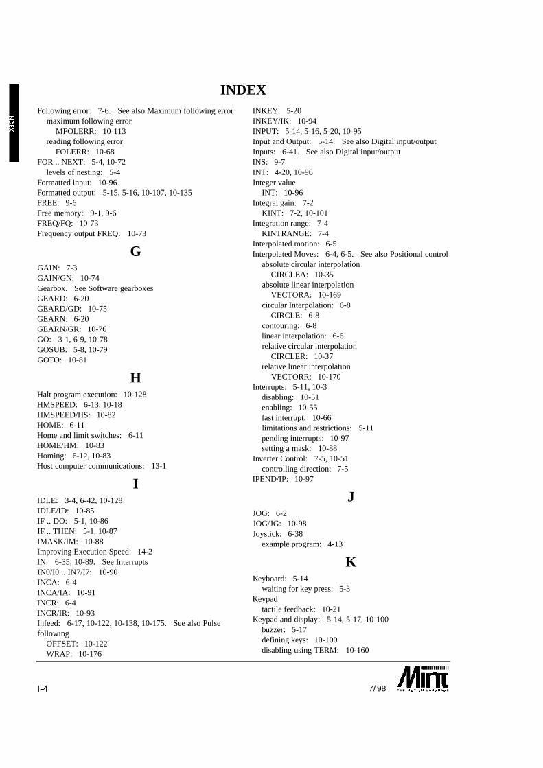
I-4 7/98
Following error: 7-6. See also Maximum following errormaximum following error
MFOLERR: 10-113reading following error
FOLERR: 10-68FOR .. NEXT: 5-4, 10-72
levels of nesting: 5-4Formatted input: 10-96Formatted output: 5-15, 5-16, 10-107, 10-135FREE: 9-6Free memory: 9-1, 9-6FREQ/FQ: 10-73Frequency output FREQ: 10-73
GGAIN: 7-3GAIN/GN: 10-74Gearbox. See Software gearboxesGEARD: 6-20GEARD/GD: 10-75GEARN: 6-20GEARN/GR: 10-76GO: 3-1, 6-9, 10-78GOSUB: 5-8, 10-79GOTO: 10-81
HHalt program execution: 10-128HMSPEED: 6-13, 10-18HMSPEED/HS: 10-82HOME: 6-11Home and limit switches: 6-11HOME/HM: 10-83Homing: 6-12, 10-83Host computer communications: 13-1
IIDLE: 3-4, 6-42, 10-128IDLE/ID: 10-85IF .. DO: 5-1, 10-86IF .. THEN: 5-1, 10-87IMASK/IM: 10-88Improving Execution Speed: 14-2IN: 6-35, 10-89. See InterruptsIN0/I0 .. IN7/I7: 10-90INCA: 6-4INCA/IA: 10-91INCR: 6-4INCR/IR: 10-93Infeed: 6-17, 10-122, 10-138, 10-175. See also Pulsefollowing
OFFSET: 10-122WRAP: 10-176
INKEY: 5-20INKEY/IK: 10-94INPUT: 5-14, 5-16, 5-20, 10-95Input and Output: 5-14. See also Digital input/outputInputs: 6-41. See also Digital input/outputINS: 9-7INT: 4-20, 10-96Integer value
INT: 10-96Integral gain: 7-2
KINT: 7-2, 10-101Integration range: 7-4
KINTRANGE: 7-4Interpolated motion: 6-5Interpolated Moves: 6-4, 6-5. See also Positional control
absolute circular interpolationCIRCLEA: 10-35
absolute linear interpolationVECTORA: 10-169
circular Interpolation: 6-8CIRCLE: 6-8
contouring: 6-8linear interpolation: 6-6relative circular interpolation
CIRCLER: 10-37relative linear interpolation
VECTORR: 10-170Interrupts: 5-11, 10-3
disabling: 10-51enabling: 10-55fast interrupt: 10-66limitations and restrictions: 5-11pending interrupts: 10-97setting a mask: 10-88
Inverter Control: 7-5, 10-51controlling direction: 7-5
IPEND/IP: 10-97
JJOG: 6-2JOG/JG: 10-98Joystick: 6-38
example program: 4-13
KKeyboard: 5-14
waiting for key press: 5-3Keypad
tactile feedback: 10-21Keypad and display: 5-14, 5-17, 10-100
buzzer: 5-17defining keys: 10-100disabling using TERM: 10-160
INDEX

I-57/98
locating the cursor: 10-109writing to using LINE: 10-107
KEYS: 10-100KINT: 7-3KINT/KI: 10-101KINTRANGE: 7-4, 10-102KINTRANGE/KR: 10-102KVEL: 7-3KVEL/KV: 10-103KVELFF: 7-3KVELFF/KF: 10-104
LLabels: 10-2
GOTO: 10-81LASTERR: 8-3, 10-105LCD display: 5-17, 10-107LED: 8-7LED status display: 8-7, 10-105
LED keyword: 8-7LED/LD: 10-105LIMIT: 6-43Limit switches. See also Error recovery
disablingDISLIMIT: 5-10, 6-43, 10-52
enabling: 10-55ENABLE: 10-55ENLIMIT: 5-10, 6-43
LIMIT: 6-43, 10-106LIMIT/LM: 10-106
LINE: 5-16, 10-107, 10-136Line editor: 9-1Linear Interpolation: 6-6LIST: 9-7LOAD: 4-17, 10-108Loading programs and data: 10-108LOCATE: 10-109Logical operators: 10-11. See also Operators
AND/&: 10-11NOT/!: 10-120OR/|: 10-124
LOOP .. ENDL: 5-6, 10-110Loops: 5-4. See also Nesting
Nesting. See alsocontinuous loops: 5-6EXIT: 10-64FOR .. NEXT: 5-4, 10-72LOOP .. ENDL: 5-6, 10-110REPEAT .. UNTIL: 5-5, 10-144terminating from: 5-7, 10-64WHILE .. ENDW: 5-5, 10-175
LOOPTIME/LT: 10-111
MMASTERINC: 6-18, 6-19, 6-20, 10-26, 10-112MASTERINC/MI: 10-112Mathematical operators: 4-20Maximum following error: 7-6. See also MFOLERR
MFOLERR: 10-113Memory: 9-1
determining free memory: 9-6out of memory: 11-2
Memory Expansion: 9-2, 10-121MFOLERR: 7-6, 10-113MFOLERR/MF: 10-113Micro stepper
configuring forCONFIG: 10-40
MINTexecution speed: 14-1
MINT Editor: 9-1MINT Host Computer Communications: 12-1.See also COMMSON. See also Comms protocolMINT Host Computer Protected Protocol: 5-23MINT Versions: 1-7MINT/3.28: 1-8, 13-1
applications diskette: 13-1buffered moves: 13-8commands: 13-7GO command: 13-8reading data: 13-6status request: 10-182writing data: 13-6
MOD: 4-20MODE: 6-34, 8-8MODE/MD: 10-114Modular arithmetic: 4-20Motion: 10-85
checking for idle: 10-85GO: 10-78IDLE: 10-85MODE: 6-34, 10-115
Motion commands: 3-1Motion error: 8-5Motion Variables: 3-1, 4-6
range checking: 3-1Motor demand
DEMAND: 10-49Motor type: 10-40
CONFIG: 10-40Move Buffer: 6-9Move pending: 6-10, 6-41MOVEA/MA: 10-116MOVECAM: 8-8, 10-27, 10-79, 10-112, 10-115, 10-150,10-158
INDEX

I-6 7/98
MOVER/MR: 10-118Multi-Axis Syntax: 3-2
AXES: 10-16default using AXES: 3-2reading more than 1 axis: 3-4referencing axes: 3-2using: 3-2using, to skip axes: 3-2
Multi-drop RS485: 1-1, 1-7, 10-1, 13-1card address: 10-33
Multi-drop systems: 1-8
NNesting: 5-7NEW: 9-7NOT: 4-20NOT/!: 10-120Numbers: 4-1. See also Operators
binary numbers: 4-1, 4-21character constants: 4-2, 5-21constant numbers: 4-2scaled integers: 4-1
OOFFLINE: 4-10, 4-11, 4-15, 9-2, 10-50, 10-121OFFSET: 6-17, 6-18, 6-19OFFSET/OF: 10-122ONERROR: 5-10, 8-5Operators
absolute valueABS: 4-20, 10-6
bitwise operatorsAND/&: 10-11AND/&, OR/|: 4-20OR/|: 10-124
Integer valueINT: 4-20, 10-96
logical operators: 10-11AND/&: 10-11AND/&, OR/, NOT/!: 4-21NOT/!: 10-120
mathematical operators– + / *: 4-20
performing logical operations: 4-21priority: 4-20relational operators: 4-21
< > = <= >= <>: 4-21Option card
reading address spacePEEK: 10-129
writing to address spacePOKE: 10-131
OR: 4-20OR/|: 10-124Out of memory: 11-2OUT/OT: 10-125OUT0/O0 .. OUT7/O7: 10-127Output Errors On SmartMove
Over current: 8-8Over temperature: 8-8Short circuit: 8-8
Outputs: 6-41, 10-125. See also Digital input/output
PPassword Protection: 9-4, 10-137PAUSE: 5-3, 10-128PEEK/PK: 10-129POFF: 10-131POKE: 10-131PON: 10-132POS: 6-13, 10-182POS/PS: 10-132Position
latching using fast interrupt: 10-66reading
POS: 10-132reading using ENCODER: 10-56writing
POS: 10-133Positional control: 6-3
absolute positional control: 6-3, 10-116correctly for slip: 10-93incremental positional control: 6-4, 10-118interpolated moves: 6-5relative positional control: 10-118velocity profile: 6-9
ACCEL: 6-9RAMP: 6-9, 10-140SPEED: 6-9
Positional error: 7-6Positional moves. See Positional control
defining new end position: 6-4, 10-91, 10-93interpolated moves: 10-35, 10-169, 10-170
Positional Resolution: 7-6quadrature counts: 7-6SCALE: 7-6, 10-150
Positioning the cursor: 10-109LOCATE: 10-109
Power to motors: 10-151Pre-defined constant keywords: 4-3PRESCALE: 10-134PRINT: 5-15PRINT/?: 10-135Process MINT: 1-7PROG: 9-8
INDEX
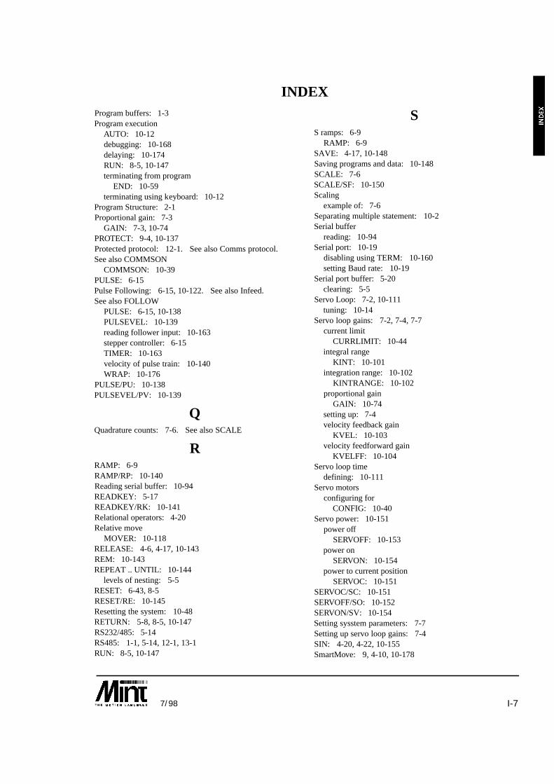
I-77/98
Program buffers: 1-3Program execution
AUTO: 10-12debugging: 10-168delaying: 10-174RUN: 8-5, 10-147terminating from program
END: 10-59terminating using keyboard: 10-12
Program Structure: 2-1Proportional gain: 7-3
GAIN: 7-3, 10-74PROTECT: 9-4, 10-137Protected protocol: 12-1. See also Comms protocol.See also COMMSON
COMMSON: 10-39PULSE: 6-15Pulse Following: 6-15, 10-122. See also Infeed.See also FOLLOW
PULSE: 6-15, 10-138PULSEVEL: 10-139reading follower input: 10-163stepper controller: 6-15TIMER: 10-163velocity of pulse train: 10-140WRAP: 10-176
PULSE/PU: 10-138PULSEVEL/PV: 10-139
QQuadrature counts: 7-6. See also SCALE
RRAMP: 6-9RAMP/RP: 10-140Reading serial buffer: 10-94READKEY: 5-17READKEY/RK: 10-141Relational operators: 4-20Relative move
MOVER: 10-118RELEASE: 4-6, 4-17, 10-143REM: 10-143REPEAT .. UNTIL: 10-144
levels of nesting: 5-5RESET: 6-43, 8-5RESET/RE: 10-145Resetting the system: 10-48RETURN: 5-8, 8-5, 10-147RS232/485: 5-14RS485: 1-1, 5-14, 12-1, 13-1RUN: 8-5, 10-147
SS ramps: 6-9
RAMP: 6-9SAVE: 4-17, 10-148Saving programs and data: 10-148SCALE: 7-6SCALE/SF: 10-150Scaling
example of: 7-6Separating multiple statement: 10-2Serial buffer
reading: 10-94Serial port: 10-19
disabling using TERM: 10-160setting Baud rate: 10-19
Serial port buffer: 5-20clearing: 5-5
Servo Loop: 7-2, 10-111tuning: 10-14
Servo loop gains: 7-2, 7-4, 7-7current limit
CURRLIMIT: 10-44integral range
KINT: 10-101integration range: 10-102
KINTRANGE: 10-102proportional gain
GAIN: 10-74setting up: 7-4velocity feedback gain
KVEL: 10-103velocity feedforward gain
KVELFF: 10-104Servo loop time
defining: 10-111Servo motors
configuring forCONFIG: 10-40
Servo power: 10-151power off
SERVOFF: 10-153power on
SERVON: 10-154power to current position
SERVOC: 10-151SERVOC/SC: 10-151SERVOFF/SO: 10-152SERVON/SV: 10-154Setting sysstem parameters: 7-7Setting up servo loop gains: 7-4SIN: 4-20, 4-22, 10-155SmartMove: 9, 4-10, 10-178
INDEX

I-8 7/98
Software Gearbox: 6-17, 6-19, 6-20, 6-21, 10-77CAM profiling. Seeclutch distance: 6-18, 6-21
SPEED: 6-9. See also VelocitySpeed Control: 6-2
JOG: 6-2, 10-98SPEED/SP: 10-155Status Display: 8-7, 10-105Stepper control
BEEPOFF: 10-21BEEPON: 10-21frequency output: 10-73
Stepper controller: 6-15Stepper motors: 10-40
configuring for: 10-40CONFIG: 10-40
STOP: 3-1, 6-16STOP Input: 6-42, 10-158
reading input: 10-159reading value of: 6-42STOP subroutine: 10-5STOPSW: 10-159
Stop motioncontrolled stop
STOP: 10-157crash stop
ABORT: 10-5STOP subroutine: 5-10, 10-5STOP/ST: 10-157STOPMODE: 10-158STOPSW: 6-43STOPSW/SS: 10-159Subroutine label: 10-2Subroutines: 5-8
calling: 5-8, 10-80defining: 5-8GOSUB: 5-8, 10-79interrupt routines: 5-11labels: 5-8, 10-2maximum number of in a program: 5-9RETURN: 5-8, 10-147
System commissioning: 10-13System Software Configuration: 7-1
TTAN: 4-20, 4-22, 10-160TERM/TM: 10-160Terminal Input/Output: 5-14
associated keywordsBEEP: 10-20BEEPOFF: 10-21BEEPON: 10-21
BINARY: 10-22BOL (Beginning of line): 10-22CHR: 10-34CLS: 10-38INKEY: 10-94INPUT: 5-16, 10-95LINE: 10-107LOCATE: 10-109POFF: 10-131PON: 10-132PRINT: 5-15, 10-135TERM: 10-160
character constants: 5-21clearing the serial port buffer: 5-21controlling use of: 10-160formatted input: 5-16formatted output: 5-16keypad and display: 5-17positioning the cursor: 10-22, 10-109reading the serial port buffer: 5-21serial port buffer: 5-20write to a line: 5-15
Terminate motion. See also Ctrl-Econtrolled stop
STOP: 10-157crash stop
ABORT: 10-6Terminate program execution: 1-4, 1-6Terminating loops: 5-7Terminating program execution: 1-6. See also Ctrl-E
END: 8-5Three channel encoder interface board: 10-177TIME/TE: 10-162TIMER: 6-16, 10-163Timer input: 10-163TIMER/TI: 10-163Timing program execution: 10-162Torque Control: 6-1
terminating: 6-1Torque: 6-1, 10-164
TORQUE/TQ: 10-164Trapezoidal profile: 6-9TRIGGER: 6-33, 10-165, 10-166, 10-167Triggered Moves: 6-33Trigonometric Functions: 4-22
COS: 10-43SIN: 10-155TAN: 10-160
TROFF: 10-167TRON: 10-168Tuning servo loop: 10-14
INDEX

I-97/98
UUni-directional control. See also Inverter controlUser timer: 10-162User units
setting: 10-150User variables: 4-5
VVariable software gearbox: 6-22. See also Cam profilingVariables: 4-5. See also Numbers. See also Motionvariables
array dataDIM: 10-49reserving space for: 10-49
associated keywordsDISPLAY: 4-6RELEASE: 4-6
clearing variables from memory: 4-6, 10-143clearing variables from memory during runtime: 4-6declaring user variables: 4-5displaying defined variables: 4-5, 10-53motion variables: 4-21
Motion variables. See non-volatile: 4-6
VECTORA: 6-6VECTORA/VA: 10-169VECTORR: 6-6VECTORR/VR: 10-170VEL/VL: 10-172Velocity. See also SPEED
reading using VEL: 10-172Velocity control: 10-98Velocity feedback gain: 7-2
KVEL: 7-2, 10-103Velocity feedforward: 7-2Velocity feedforward gain
KVELFF: 7-3Velocity Profile: 6-9. See also S ramps acceleration
ACCEL: 10-7ACCELTIME: 10-8RAMP: 10-140
VER: 10-173Version of MINT: 10-173Versions: 1-7VPU: 10-156
WWAIT/WT: 10-174WHILE .. ENDW: 5-5, 10-175WRAP: 6-16, 10-139WRAP/WR: 10-176
XXENCODER: 10-18, 10-72, 10-134, 10-177, 10-178XIO: 10-179XIO/XI: 10-179XIO0..7: 10-179XOUT/XO: 10-181
ZZERO: 6-15Zero position. See also DatumingZERO/ZR: 10-182ZZ: 10-183
INDEX

I-10 7/98
INDEX

���� ��������� ��������������������������� ������������������
��������������������������� ������!���"�#"��$%
����������
��� �������������������
���������

����������� ���!�����������"�#����$$%�
&""�����������������
This manual is copyrighted and all rights are reserved. This document may not, in whole or in part,be copied or reproduced in any form without the prior written consent of Optimised Control.
Optimised Control makes no representations or warranties with respect to the contents hereof andspecifically disclaims any implied warranties of fitness for any particular purpose. The information inthis document is subject to change without notice. Optimised Control assumes no responsibility forany errors that may appear in this document.
MINT ™ is a registered trademark of Optimised Control Ltd.
���!�����������"�'��"�( ���� ������)
�������*���� �����+)
Optimised Control Ltd178-180 Hotwell RoadBristolBS8 4RPU.K.Tel: (+44) (117) 987 3100FAX: (+44) (117) 987 3101BBS: (+44) (117) 987 3102
,������������)
Optimised Control Inc3923 Coconut Palm DriveSuite 107TampaFloridaUSATel: (+1) (813) 626 0780Fax: (+1) (813) 626 0361
-���������!)
Optimised Control (NZ) Ltd5 Matija PlaceRed BeachHibiscus CoastNew ZealandTel: (+64) (0) 9426 6627Fax: (+64) (0) 9426 6762

.����"����������������
����� ���� ������� �������
1.0 Aug 92 MN00105-001 First release1.1 Aug 95 MN00105-002 Corrected digital outputs1.2 Mar 95 MN00105-003 Tidied up and added overview section

��������
-�����
��� ������ ��������������������������������������������������������������������������������
����/�������"���������������������������������������������������������������������������������
������.�������������"��� ����������������������������������������������������������������������������������� �
����.����""�������0�.��������"����������������������������������������������
����1��������2����� ����������������������������������������������������������������������������
������3��� �2�����������������������������������������������������������������������������������������������������
����� ��������-���" ��������������������������������������������������������������������������������������������
����.�!������������������������������������������������������������������������������������������������
���3�/�����������"������������������ ������������������������������������������������������������� 3
��3�4��! ���� ������ ����������������������������������������������������������������������������3
���������""����� ������������������������������������������������������������������������%
����$%( ���5�6�����������-������������������������������������������������������������7
����� �����/�����������������������������������������������������������������������������������������
���#�!�������������������������������������������������������������������������������������������������
��3��!�������� �������������������������������������������������������������������������������������
��8�������"��� �������������������������������������������������������������������������������������
��8���5�����"������������������������������������������������������������������������������������������������������ �
��8���5�����"� ������ ������������������������������������������������������������������������������������������� �3
��8��&��"����������� ���������������������������������������������������������������������������������������� �3
��8�3�-�"�������5�������� ����������������������������������������������������������������������������������� �8
��%������� ������ ���������������������������������������������������������������������������������%
��%���/�������!�������"������������������������������������������������������������������������������������� �%
��9�-� �� �����������������������������������������������������������������������������������������������9
��9���,����-� ���������������������������������������������������������������������������������������������������� �9
��9���2�������2��:(�� ����������������������������������������������������������������������������������������� �9
��7�������� �������������������������������������������������������������������������������������������7
��$�.����""������ ���������������������������������������������������������������������������������$
��$��������� ����� ������������������������������������������������������������������������������������������������ �$
��$������������� ��������������������������������������������������������������������������������������������������� �$
��$������������� ������������������������������������������������������������������������������������������������� �;
��$�3������������ ��������������������������������������������������������������������������������������������������� �;

��������
-������
��$�8�4������������� ���������������������������������������������������������������������������������������������� �;
���;������"�-��� ����������������������������������������������������������������������������������������
���;���������������������������������������������������������������������������������������������������������������� ��
���;�����378��������������������������������������������������������������������������������������������������������� ��
�� ���������������� ����������������������������������������������������������8
���-���&�����!��� �����������������������������������������������������������������������������8
����������"�5����������� �������������������������������������������������������������������������������������� �8
���-������������������������������������������������������������������������������������������������%
3��<��=���������5���"��������������������������������������������������9
3���3('���������-���&������!���������������������������������������������������9
3����������"�5������������������������������������������������������������������������������������������������ �9
8�������&�����������������������������������������������������������������������������7
%��/���������""���2��:�"��������������� ���������������������������$
%���5�����"� ������)� ,/����������������������������������������������������������������������;
%���5�����"�������)��6 �����������������������������������������������������������������������������;
%�� .��#�.�/ ������������������������������������������������������������������������������������;
%�3�������5����������������)�&6&( ,/ ��������������������������������������������
%�8�&��"���������������������)�&6&����������������������������������������������
%�%�-� ��)�-'��.������������������������������������������������������������������������������
%�9����������������������������������������������������������������������������������������
%�7����������� ����������������������������������������������������������������������������������������
%�$�3�$������378 ����������������������������������������������������������������������������������

������
�������������� ���������)������ ��� -�����
��� ������
The EuroServo/3 controller is aprogrammable computer designedspecifically for motion control of up tothree independent axes, integrated onone extended eurocard sized printedcircuit board. The controller is suppliedas a printed circuit board and isnormally built up in a 19" rack with theEuroServo/3 back plane, a power supplyand options such as the operator keypadwith LCD message display or 24 I/0 expansion board.
The major features of the controller are as follows:
� Three axis position controller for closed loop servo motors
� Stand-alone operation or controlled by host computer over RS232/485 link, up to 16 cards onRS485 multi drop link
� Extended eurocard format (100 by 220mm) using surface mount technology, ideal for machine"design-in".
� Incremental encoder feedback, two channel plus index
� 12 bit analogue +/-10V servo amplifier outputs
� Easy to use BASIC-like motion control language, MINT
� 28k bytes non-volatile program/data memory
� On board program editor
� Circular and linear interpolation
� 8 uncommitted digital inputs and outputs for machine control
� 3 Limit switches, 3 Home switches and Error input
� Three 10 bit analogue inputs for interface to joy-stick or sensors
� Pulse follower input
� +5V, +/-12V, 24V power requirement
� Expansion port for option boards such as extended I/O
���� /�������"��������������

������
�������������� ���������)������ ��� -�����
������ .�������������"���
����� ����� � 1 input per axis. Provides end of travel protection. Crash stop allaxes when active.
� PNP Opto-isolated. Connect to normally closed switch to User V+.� �� ����� � 1 input per axis. Provides reference position for the axis.
� PNP Opto-isolated. Connect to normally closed switch to User V+.�� � ����� � 1 input per controller. Brings all axes to a controlled stop when
active.� PNP Opto-isolated. Connect to normally closed switch to User V+.
��� � ����� � 1 input per controller. Brings all axes to the crash stop when active.� PNP Opto-isolated.� Input sense software configurable.
��� ������� ����� � 8 input lines.� PNP opto-isolated.� Logical one when floating or pulled low.� Logical zero when connected to User V+.
��� ������� ����� � 8 output lines driven by Darlington array.� 50mA continuous source on all channels.� 350mA max source per channel, 700mA max for all 8 channels.
��� ��������� � 1 input per controller.� PNP opto-isolated.� Latches position of all axes within 50 microseconds on rising edge.
������ ����� � Voltage free change over relay rated at 1A @ 24V.� 1 output per controller.� Fail safe operation: relay de-energised on an error.
���� �� ����� � 3 independent analogue channels.� 10 bit resolution.� Jumper selectable for ±10V (differential) or 0-5V operation.
���� �� ����
������ ��������
� 1 output per axis for motor demand signal.� ±10V output (±0.1%).� 12 bit resolution (4.9mV).� Additional analogue output provided for system tuning and general
use.��� ����� � Counts rising and falling edge of pulses. Used for software
gearboxes.� Max input frequency of 150kHz.� Opto-isolated� Opto-isolated PNP direction input to change operation of up/down
counter.� Opto-isolated PNP reset input clears counter on a rising edge.
��! ��� ����� � Encoder input per axis for positional feedback via incrementalencoder.
� Operates with both single ended (TTL or open collector) ordifferential (TTL or RS422) output type. Differential isrecommended.
� Accepts three channel increment encoders (A, B and Z). A and Bchannels are quadrature decoded.
� Minimum requirement: Channel A and B single ended TTL.� Maximum encoder frequency: 5.3MHz quadrature count.
������ � ��� � RS232 or full duplex 4 wire RS485. Factory set.� Connections brought out on 9-way male D-type connector.� 9600 baud, 1 start bit, 8 data bits, 1 stop bit, no parity.
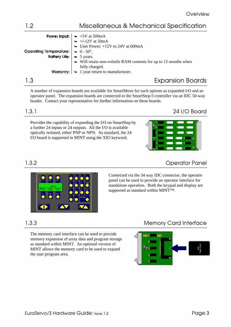
������
�������������� ���������)������ ��� -����
���� .����""�������0�.��������"��������������
� "�� ����� � +5V at 500mA� +/-12V at 50mA� User Power: +12V to 24V at 600mA
��������� #���������� � 0 - 50°.$�����% ��&�� � 5 years.
� Will retain non-volatile RAM contents for up to 12 months whenfully charged.
'������%� � 1 year return to manufacturer.
��� �1��������2�����
A number of expansion boards are available for SmartMove for such options as expanded I/O and anoperator panel. The expansion boards are connected to the SmartStep/3 controller via an IDC 50-wayheader. Contact your representative for further information on these boards.
����� �3��� �2����
Provides the capability of expanding the I/O on SmartStep bya further 24 inputs or 24 outputs. All the I/O is availableoptically isolated, either PNP or NPN. As standard, the 24I/O board is supported in MINT using the XIO keyword.
����� ��������-���"
Connected via the 34 way IDC connector, the operatorpanel can be used to provide an operator interface forstandalone operation. Both the keypad and display aresupported as standard within MINT™.
���� .�!������������������
The memory card interface can be used to providememory expansion of array data and program storageas standard within MINT. An optional version ofMINT allows the memory card to be used to expandthe user program area.

������
�������������� ���������)������ ��� -����3
���3� /�����������"������������������
The three channel encoder interface board can be usedto provide position verification of the stepper motorposition. This board is supported as standard withinMINT™ through the use of the XENCODER keyword.
��3� 4��! ���� ������
EuroServo/3 comes as standard with Process MINT™ (denoted by a /P on the version number). Anumber of other firmware options are available:
������ ���� Process MINT™, as standard with EuroServo.3, incorporates suchmotion control features as software gearboxes, cam profiles andflying shears. Process MINT™ supports up to 3 axes of linearinterpolation but does not support circular interpolation.
Is must be noted that Process MINT™ supports cam profiles andflying shears on the first 2 axes only (Axes 0 and 1).
������������ ���� Interpolation MINT™ provides full linear and circular interpolationwithin the MINT™ environment. Interpolation MINT™ does notsupport the cam profiling and flying shear capabilities of ProcessMINT™. A subset of Process MINT’s software gearboxes aresupported.
��������� MINT/3.28 is intended specifically for systems where a hostcomputer sends motion control commands to the controller in realtime. Motion control programs are not supported on the controller,but commands are sent by a host computer by means of datapackets.
MINT/3.28 only supports a subset of the MINT command set,namely the motion control commands. The Process MINTcommand set is not supported.
MINT/3.28 will operate over either an RS232 or RS485 link. Thephysical constraints of RS232 allow only point-to-pointcommunication, i.e. one host computer can talk to one controller,RS485 provides longer transmission distances and allows a singlehost computer to communicate with up to 16 controllers on onemulti-drop link.
Within a multi-drop 485 system using MINT/3.28, a controllercannot act as a host to other controllers on the system.
cTERM provides the facility to send instructions as MINT/3.28datapackets to facilitate testing. The Applications and UtilitiesDiskette also contains the C source code (MINT328 sub-directory)for creating MINT/3.28 datapackets for transmission.
���� The HPGL EPROM (sometimes referred to as OCGL) provides asubset of the HPGL graphics language for use with pen plotters,routers and knife cutters. The following features are not supported:
� No support for text strings (LB command) or character fonts.
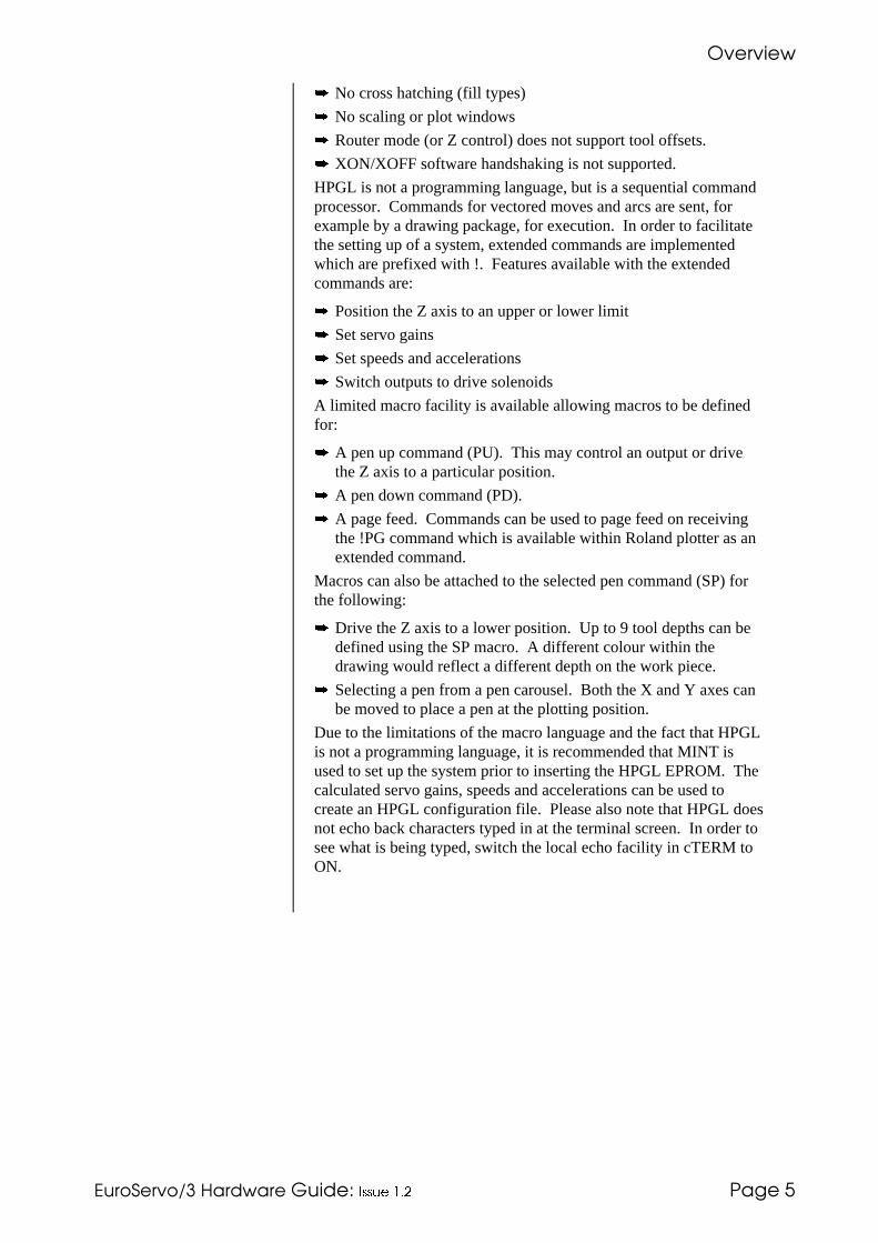
������
�������������� ���������)������ ��� -����8
� No cross hatching (fill types)
� No scaling or plot windows
� Router mode (or Z control) does not support tool offsets.
� XON/XOFF software handshaking is not supported.
HPGL is not a programming language, but is a sequential commandprocessor. Commands for vectored moves and arcs are sent, forexample by a drawing package, for execution. In order to facilitatethe setting up of a system, extended commands are implementedwhich are prefixed with !. Features available with the extendedcommands are:
� Position the Z axis to an upper or lower limit
� Set servo gains
� Set speeds and accelerations
� Switch outputs to drive solenoids
A limited macro facility is available allowing macros to be definedfor:
� A pen up command (PU). This may control an output or drivethe Z axis to a particular position.
� A pen down command (PD).
� A page feed. Commands can be used to page feed on receivingthe !PG command which is available within Roland plotter as anextended command.
Macros can also be attached to the selected pen command (SP) forthe following:
� Drive the Z axis to a lower position. Up to 9 tool depths can bedefined using the SP macro. A different colour within thedrawing would reflect a different depth on the work piece.
� Selecting a pen from a pen carousel. Both the X and Y axes canbe moved to place a pen at the plotting position.
Due to the limitations of the macro language and the fact that HPGLis not a programming language, it is recommended that MINT isused to set up the system prior to inserting the HPGL EPROM. Thecalculated servo gains, speeds and accelerations can be used tocreate an HPGL configuration file. Please also note that HPGL doesnot echo back characters typed in at the terminal screen. In order tosee what is being typed, switch the local echo facility in cTERM toON.

������ �����
�������������� ���������)������ ��� -����%
��� ������""�����
mas/mc
Option Bus
Keypad Interface
EP
RO
M
CP
U
LED StatusDisplay
Serial Port
LCD ContrastAdjust
Card AddressSwitch
Analogue InputVoltage Select ionJumper Posit ions
+/-10V1
2
3
0 to 5V1
2
3
96 Way DIN Connector
������ �� �� ������� ������

������ �����
�������������� ���������)������ ��� -����9
Operatorpanel Address
96-wa
yD
INC
on
ne
cto
r
CPU
Card
50W
ay
Op
tion
Slot
34w
ay
StatusDisplay
Serial PortRS232/485
Switch
Option Bus Connector
DIN
41612C
on
ne
cto
r
Option Board:
I/O expansion
Custom design
Operator Panel
Controller
Connector
34w
ay
Display adaptorboard
Buzzer
LCD 20x4 Op
to-iso
lato
rs
ref:masfig2/isg
Backplane Board
Eprom
������ �� ����������� ���� ������ ����� �������
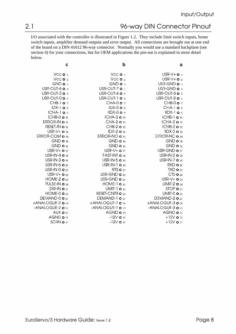
������ �����
�������������� ���������)������ ��� -����7
���� $%( ���5�6�����������-�����
I/O associated with the controller is illustrated in Figure 1.2. They include limit switch inputs, homeswitch inputs, amplifier demand outputs and error output. All connections are brought out at one endof the board on a DIN 41612 96-way connector. Normally you would use a standard backplane (seesection 4) for your connections, but for OEM applications the pin-out is explained in more detailbelow.
c b a
��� � ��� � ������ �
��� � ��� � ������ �
� � � � ����� �
������ �� � ������ �� � ����� �
������ �� � ������ �� � ������ �� �
������ �� � ������ �� � ������ �� �
����� � ����� � ����� �
����� ����� �����
������ ������ ������
������ �� ������ �� ������ ��
������� �� ����� �� ������ ��
���� �� �� ����� �� ������ ��
������ �� ����� �� ������ ��
��������� �� ������� �� ������� ��
� �� � �� � ��
� �� � �� � ��
������ �� ������ �� ����� ��
������� � ��� �� � ������� �
������� � ������� � ������� �
������� �� ������� �� ��� ��
������� �� � � �� �� ��
������ �� ����� �� � � ��
������ �� ����� �� ������ ��
�!���� �� ������ �� !��� �� ��
����� �� !��� �� �� � � ��
������ �� ���� �� � �� !��� �� ��
������� �� ������� �� ������� ��
���!����� � ���!����� � ���!����� �
���!����� � ���!����� � ���!����� �
��� �� �� �� �� ��
�� �� ���� �� ���� ��
��� �� ���� �� ���� ��

������ �����
�������������� ���������)������ ��� -����$
$%( ����������������(���
��� �� ����� �� �� ��
DEMAND-0 Demand signal out, +/-10V, axis 0 c27 DEMAND-1 Demand signal out, +/-10V, axis 1 b27 DEMAND-2 Demand signal out, +/-10V, axis 2 a27
CHA-0 Encoder channel A, true, axis 0 b7!CHA-0 Encoder channel A, compliment, axis 0 b10 CHB-0 Encoder channel B, true, axis 0 a7!CHB-0 Encoder channel B, compliment, axis 0 c10 IDX-0 Encoder INDEX, true, axis 0 b8!IDX-0 Encoder INDEX, compliment, axis 0 b9
CHA-1 Encoder channel A, true, axis 1 a8!CHA-1 Encoder channel A, compliment, axis 1 c9 CHB-1 Encoder channel B, true, axis 1 c7!CHB-1 Encoder channel B, compliment, axis 1 a10 IDX-1 Encoder INDEX, true, axis 1 c8!IDX-1 Encoder INDEX, compliment, axis 1 a9
CHA-2 Encoder channel A, true, axis 2 b11!CHA-2 Encoder channel A, compliment, axis 2 a11 CHB-2 Encoder channel B, true, axis 2 b12!CHB-2 Encoder channel B, compliment, axis 2 a12 IDX-2 Encoder INDEX, true, axis 2 b13!IDX-2 Encoder INDEX, compliment, axis 2 a13
LIMIT-0 Limit input, axis 0 a26 HOME-0 Home input, axis 0 c26
LIMIT-1 Limit input, axis 1 b25 HOME-1 Home input, axis 1 b24
LIMIT-2 Limit input, axis 2 a24 HOME-2 Home input, axis 2 c23
PULSE-IN Pulse input, pulse follower c24 DIR-IN Direction input, pulse follower c25
RESET-CNTR Timer 2 reset input b26 RST-IN System reset, input c12 STOP Stop execution, input a25
ERROR-COM Common pin of error output relay c14 ERROR-NO Normally Open pin of error output relay b14 ERROR-NC Normally Closed pin of error output relay c14 ERROR-IN Motion/System error input c11 FAST-INT User hardware INTERRUPT b18
USR-IN-0 User input, bit 0 c21 USR-IN-1 User input, bit 1 b20 USR-IN-2 User input, bit 2 a18 USR-IN-3 User input, bit 3 c19 USR-IN-4 User input, bit 4 c18 USR-IN-5 User input, bit 5 b19

������ �����
�������������� ���������)������ ��� -�����;
��� �� ����� �� �� ��
USR-IN-6 User input, bit 6 c20 USR-IN-7 User input, bit 7 a19
USR-OUT-0 User output, bit 0 c6 USR-OUT-1 User output, bit 1 b6 USR-OUT-2 User output, bit 2 a6 USR-OUT-3 User output, bit 3 c5 USR-OUT-4 User output, bit 4 b5 USR-OUT-5 User output, bit 5 a5 USR-OUT-6 User output, bit 6 c4 USR-OUT-7 User output, bit 7 b4
+ANALOGUE-1 Analogue input 1, non-inverting b28-ANALOGUE-1 Analogue input 1, inverting b29
+ANALOGUE-2 Analogue input 2, non-inverting c28-ANALOGUE-2 Analogue input 2, inverting c29
+ANALOGUE-3 Analogue input 3, non-inverting a28-ANALOGUE-3 Analogue input 3, inverting a29
TXD Transmitted data (TxD true) a21 RXD Received data (RxD true) a20 RTS Request to send (TxD compliment) b21 CTS Clear to send (RxD compliment) a22
-12V -12V @ 100mA b31,b32+12V +12V @ 100mA a31,a32 5V + 5V @ 500mA c1,c2,b1,b2GND 0V Digital ground
AGND 0V Analogue ground b30,a30USR-V+ power for opto isolation (+12 to +24)
USR-GND ground for opto isolationSCRN 0V Cable screen c32
All of the digital motion and uncommitted inputs and uncommitted outputs are optically isolated, adetailed description can be found later in this document. Inputs are always in their logically 'active'state (ie STOP in its active state will cause motion to cease) unless they are pulled up to user power(USR-V+) by external circuitry, this provides fail safe operation. Before the system will operate, youmust connect the limit switches and the stop switch either to their respective switches or to USR-V+.Failure to do so will result in a limit error on the controller and a stop condition. This is indicated bythe LED status display showing either an 'L' or an 'S'. Details of how to set up the controller can befound in the Getting Started Guide.
The following sections explain each of the I/O types in detail. A pin-out table lists all the relevantpins on the DIN connector and the backplane for that I/O function. The pin number on the DINconnector is given in brackets. The backplane detail shows the connector block followed by the pinname.

������ �����
�������������� ���������)������ ��� -������
���� � �����/����
Because the inputs are active when floating they must be tied to USR-V+ through normally closedswitches. The system will not operate correctly with normally open switches.
��� #�!���������
-�����)
��� ���!� � $�!(����� ��!����� �&'�'(�� )��%* +,�-"&'�'(� &� &���� ������ �.�� �
&'�'(� )/�* +,�-"&'�'(� & &���� ������ �.��
&'�'(�� )��0* +,�-"&'�'(� &� &���� ������ �.�� �
12��34 +,�-"&'�'(� 15 1��� 6����
In a typical application, the limit switch inputs would be connected to normally closed micro switcheson the axis. Hitting the limit switch will cause the switch to become open circuit, the respective inputthen becomes active internally, resulting in a limit error and the axis coming to an immediate stop. Alimit error is indicated by an 'L' on the LED status display, and the ERROR keyword will return thevalue 3 when read. See the MINT Programming Guide for more details on the ERROR keyword anderror handling within MINT.
Because there is only one limit input per axis, if two end-of-travel limit switches are fitted then theymust both be connected in series as shown below.
LIMIT INPUTLIMIT FORWARD LIMIT REVERSE
USER POWER
limit/mc
������ �� ��� !���� � "�� �#���$ �� �����
A possible problem with this arrangement is that is it not possible to determine in software which end-of-travel switch has been hit by simply reading the limit input. This can be overcome by introducing adouble pole limit switch at one end of the axis and connecting this to the home input or a spare digitalinput. This means that when a limit switch is hit the program can determine whether this is theforward or reverse limit by reading the status of the home switch or relevant digital input.
LIMIT INPUTLIMIT FORWARD LIMIT REVERSE
USER POWER
HOME SWITCHHOME INPUT
Note: Switches should be normally closed
masfig15
������ �� ��� !���� � � %����& "�� �� �����
In many applications it is necessary to have separate limit and home switches. In these cases it is bestto arrange the active areas of the switches to be set up as shown below.

������ �����
�������������� ���������)������ ��� -������
Limit Active Area
Home Active Area
Travel
home/mc/0392
������ �� !�����%��� �#���$ ������ �����
Hitting a limit switch causes an error which is handled in software by the ONERROR subroutine,details of this are given in the MINT programming guide.
In an application where not all 3 axes are being used, the redundant axes must have their respectivelimit switches tied to USR-V+ for normal operation. Alternatively the MINT keyword DISLIMIT canbe used to disable the detection of limit switches.
The state of the limit switches can be read using the MINT LIMIT keyword. A value of 1 (logicallyactive) will be returned if the limit input is low or floating (switch open) and 0 (logically inactive) ifconnected to USR-V+ (switch closed).
Figure 2.4 shows the input buffer circuit and normal connections for all motion inputs.
VCC
10K
USER POWER
UNCOMMITED AND MOTION INPUTS
INPUT
OPTO
2K2
74HCT244
USER GNDmasfig13
������ �' & "�� ��((�� ������� (�� !����) %���) ���") ����� � ) �����) �� � � *����
��� ���
��3� �!��������
-�����)
��� ���!� � $�!(����� ��!����� �+,�-�� )��%* +,�-"&'�'(� +� +��� ������ �.�� �
+,�-� )/�0* +,�-"&'�'(� + +��� ������ �.��
+,�-�� )���* +,�-"&'�'(� +� +��� ������ �.�� �
12��34 +,�-"&'�'(� 15 1��� 6����
Three home inputs are provided, one for each axis. Like the limits these inputs require normallyclosed switches for normal operation. Unlike the limit switches, however, they do not have to beconnected if they are not used.
If the limit switch is used as a datum point, both the limit input and the home input must be connectedtogether. Noisy environments can cause glitches on the limit switches which may result in a limiterror during homing. A 100nF ceramic capacitor connected between the limit input and groundshould eliminate this problem.

������ �����
�������������� ���������)������ ��� -�����
The state of the home switches can be read using the MINT HOME keyword. A value of 1 (active)will be returned if the home input is low or floating (switch open) and 0 (inactive) if connected toUSR-V+(switch closed).
The input buffer circuit is shown below:
VCC
10K
USER POWER
UNCOMMITED AND MOTION INPUTS
INPUT
OPTO
2K2
74HCT244
USER GNDmasfig13
��8� ������"���
The controller provides 8 uncommitted digital inputs and 8 uncommitted digital outputs. These areaccessed through the MINT keywords IN and OUT.
��8��� 5�����"�������
-�����)
��� ���!� � $�!(����� ��!����� �12��'��� )��* '�� � 1��� ��6�� /�� �
12��'�� )/��* '�� 1��� ��6�� /��
12��'��� )�7* '�� � 1��� ��6�� /�� �
12��'��� )�$* '�� � 1��� ��6�� /�� �
12��'��0 )�7* '�� 0 1��� ��6�� /�� 0
12��'�� )/$* '�� 1��� ��6�� /��
12��'��% )���* '�� % 1��� ��6�� /�� %
12��'��8 )�$* '�� 8 1��� ��6�� /�� 8
12��34 '�� 15 1��� 6����
The uncommitted inputs are buffered and interpreted in the same way as the home and limit inputswith a floating or low input reading as a 1 and an input connected to USR-V+ reading as a 0. Thestate of the inputs is read using the MINT IN keyword.
The input buffer circuit is shown in figure 2.5.
OUTPUT
INDUCTIVELOAD
USER GND
USER POWER
USER POWER
10k10k
OPTO ISOLATOR
D
CLK
Q
470R
LATCH
UNCOMMITED OUTPUTS
FIG14
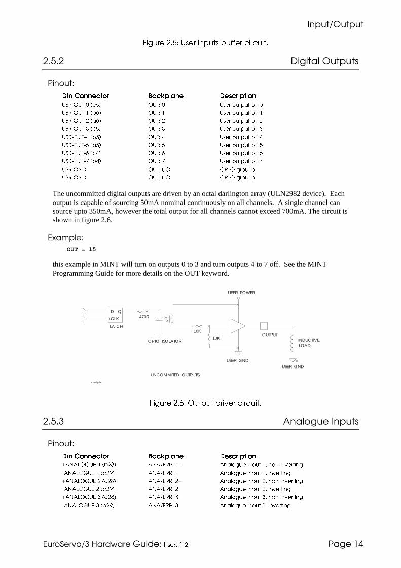
������ �����
�������������� ���������)������ ��� -�����3
������ �+ ,��� � "��� ��((�� �������
��8��� 5�����"� ������
-�����)
��� ���!� � $�!(����� ��!����� �12��,1(�� )�%* ,1(� � 1��� ���6�� /�� �
12��,1(� )/%* ,1(� 1��� ���6�� /��
12��,1(�� )�%* ,1(� � 1��� ���6�� /�� �
12��,1(�� )�* ,1(� � 1��� ���6�� /�� �
12��,1(�0 )/* ,1(� 0 1��� ���6�� /�� 0
12��,1(� )�* ,1(� 1��� ���6�� /��
12��,1(�% )�0* ,1(� % 1��� ���6�� /�� %
12��,1(�8 )/0* ,1(� 8 1��� ���6�� /�� 8
12��9�: ,1(� 19 ,5(, ;�����
12��9�: ,1(� 19 ,5(, ;�����
The uncommitted digital outputs are driven by an octal darlington array (ULN2982 device). Eachoutput is capable of sourcing 50mA nominal continuously on all channels. A single channel cansource upto 350mA, however the total output for all channels cannot exceed 700mA. The circuit isshown in figure 2.6.
�1�!�"�)
OUT = 15
this example in MINT will turn on outputs 0 to 3 and turn outputs 4 to 7 off. See the MINTProgramming Guide for more details on the OUT keyword.
USER POWER
470R
LATCH
D Q
CLK
OPTO ISOLATOR
10K
10KOUTPUT
INDUCTIVELOAD
USER GNDUSER GND
UNCOMMITED OUTPUTS
masfig14
������ �- .��"�� ������ �������
��8�� &��"�����������
-�����)
��� ���!� � $�!(����� ��!����� �4<�<&,91-� )/�7* <�<"-��� 4 <����;�� ��6�� = ������������;
�<�<&,91-� )��$* <�<"-��� � <����;�� ��6�� = ��������;
4<�<&,91-�� )��7* <�<"-��� �4 <����;�� ��6�� �= ������������;
�<�<&,91-�� )��$* <�<"-��� �� <����;�� ��6�� �= ��������;
4<�<&,91-�� )��7* <�<"-��� �4 <����;�� ��6�� �= ������������;
�<�<&,91-�� )��$* <�<"-��� �� <����;�� ��6�� �= ��������;
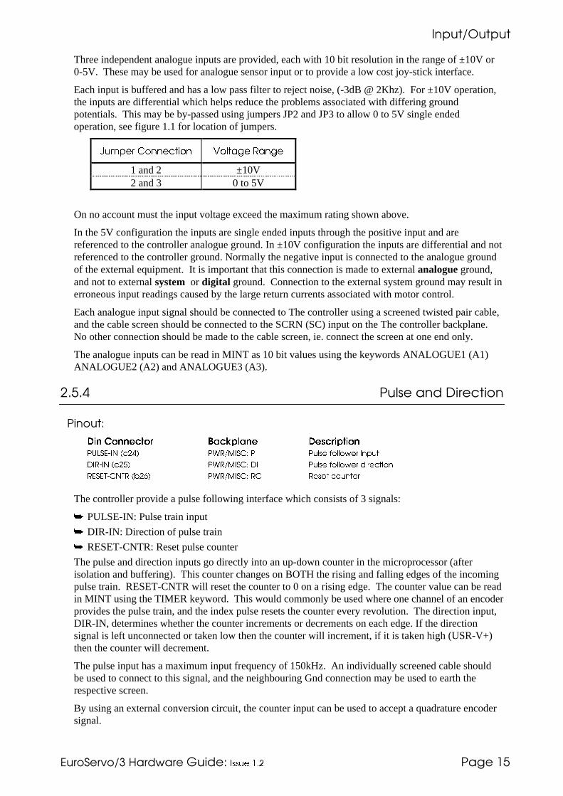
������ �����
�������������� ���������)������ ��� -�����8
Three independent analogue inputs are provided, each with 10 bit resolution in the range of ±10V or0-5V. These may be used for analogue sensor input or to provide a low cost joy-stick interface.
Each input is buffered and has a low pass filter to reject noise, (-3dB @ 2Khz). For ±10V operation,the inputs are differential which helps reduce the problems associated with differing groundpotentials. This may be by-passed using jumpers JP2 and JP3 to allow 0 to 5V single endedoperation, see figure 1.1 for location of jumpers.
"#$%&' �())&�*+() �(,*-.& �-).&
1 and 2 ±10V2 and 3 0 to 5V
On no account must the input voltage exceed the maximum rating shown above.
In the 5V configuration the inputs are single ended inputs through the positive input and arereferenced to the controller analogue ground. In ±10V configuration the inputs are differential and notreferenced to the controller ground. Normally the negative input is connected to the analogue groundof the external equipment. It is important that this connection is made to external analogue ground,and not to external system or digital ground. Connection to the external system ground may result inerroneous input readings caused by the large return currents associated with motor control.
Each analogue input signal should be connected to The controller using a screened twisted pair cable,and the cable screen should be connected to the SCRN (SC) input on the The controller backplane.No other connection should be made to the cable screen, ie. connect the screen at one end only.
The analogue inputs can be read in MINT as 10 bit values using the keywords ANALOGUE1 (A1)ANALOGUE2 (A2) and ANALOGUE3 (A3).
��8�3� -�"�������5��������
-�����)
��� ���!� � $�!(����� ��!����� �51&2-�'� )��0* 5>�"�'2#� 5' 5���� �������� ��6��
:'��'� )��* 5>�"�'2#� :' 5���� �������� ���������
�-2-(�#�(� )/�%* 5>�"�'2#� �# ����� �������
The controller provide a pulse following interface which consists of 3 signals:
� PULSE-IN: Pulse train input
� DIR-IN: Direction of pulse train
� RESET-CNTR: Reset pulse counter
The pulse and direction inputs go directly into an up-down counter in the microprocessor (afterisolation and buffering). This counter changes on BOTH the rising and falling edges of the incomingpulse train. RESET-CNTR will reset the counter to 0 on a rising edge. The counter value can be readin MINT using the TIMER keyword. This would commonly be used where one channel of an encoderprovides the pulse train, and the index pulse resets the counter every revolution. The direction input,DIR-IN, determines whether the counter increments or decrements on each edge. If the directionsignal is left unconnected or taken low then the counter will increment, if it is taken high (USR-V+)then the counter will decrement.
The pulse input has a maximum input frequency of 150kHz. An individually screened cable shouldbe used to connect to this signal, and the neighbouring Gnd connection may be used to earth therespective screen.
By using an external conversion circuit, the counter input can be used to accept a quadrature encodersignal.

������ �����
�������������� ���������)������ ��� -�����%
The buffer circuit for these inputs is shown below:
.
VCC
10K
USER POWER
UNCOMMITED AND MOTION INPUTS
INPUT
OPTO
2K2
74HCT244
USER GNDmasfig13
��%� ������ ������
-�����)
��� ���!� � $�!(����� ��!����� �:-�<�:�� )��8* <�<�,1(� :� :����� ��;��� ��� ?�3
:-�<�:� )/�8* <�<�,1(� : :����� ��;��� ��� ?�3
:-�<�:�� )/�8* <�<�,1(� :� :����� ��;��� ��� ?�3
<9�: )/��=���* <�<�,1(� <9 <����;�� 9�����
2#�� )���* <�<�,1(� 2# 2����� ����� 6����
The controller provides three ±10V (±0.1%) analogue outputs for motor demand, one for each servoaxis. A 12 bit DAC is used which gives a resolution of 4.9mV. The signals are brought out on screwterminals on the backplane.
��%��� /�������!�������"�����
After connecting motor, encoder and the required inputs you must ensure that the sense of yourencoder is correct with respect to the motor armature connections, this can be achieved by applying alittle torque (constant DAC output) to the system and testing to see if the axis is responding correctly.
In order to test the sense of the encoder you should perform the following steps, preferably with themotor shaft in free air, disconnected from your system mechanics:
• Apply power to the controller, since the servo loop parameters default to zero, the motorwill have no power applied to it on power up. If all is well, the LED status display will showan '8'.
• Apply a little positive torque to the system:
TQ = 5
If the motor does not move, increase the torque by a value of 1 until the motor startsmoving. When the motor is rotating, read back the position using the POS keyword:
? POS
re-enter the above line. The position should have increased. If the position has decreased,the armature connections are the wrong way round. If the position does not change, thenthere is a fault with the encoder connections.
You now need to set up the system gains for optimum response, which is discussed in the GettingStarted Guide.
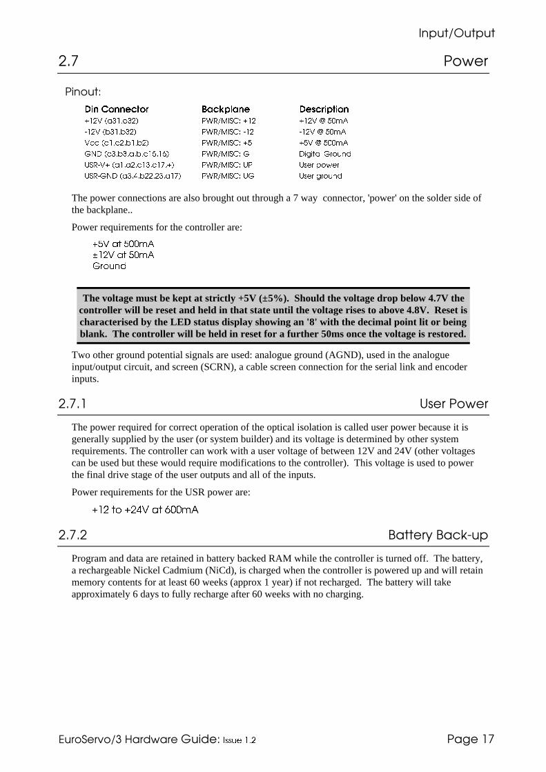
������ �����
�������������� ���������)������ ��� -�����9
��9� -� ��
-�����)
��� ���!� � $�!(����� ��!����� �4�3 )��=���* 5>�"�'2#� 4� 4�3 @ ��<
��3 )/�=/��* 5>�"�'2#� �� ��3 @ ��<
3�� )�=��=/=/�* 5>�"�'2#� 4 43 @ ���<
9�: )��=/�=�=/=�=%* 5>�"�'2#� 9 :�;���� 9�����
12��34 )�=��=��=�8=4* 5>�"�'2#� 15 1��� 6����
12��9�: )��=0=/��=��=�8* 5>�"�'2#� 19 1��� ;�����
The power connections are also brought out through a 7 way connector, 'power' on the solder side ofthe backplane..
Power requirements for the controller are:
��� -* ���$�
/��� -* ��$�
'(#)0
The voltage must be kept at strictly +5V (±5%). Should the voltage drop below 4.7V thecontroller will be reset and held in that state until the voltage rises to above 4.8V. Reset ischaracterised by the LED status display showing an '8' with the decimal point lit or beingblank. The controller will be held in reset for a further 50ms once the voltage is restored.
Two other ground potential signals are used: analogue ground (AGND), used in the analogueinput/output circuit, and screen (SCRN), a cable screen connection for the serial link and encoderinputs.
��9��� ,����-� ��
The power required for correct operation of the optical isolation is called user power because it isgenerally supplied by the user (or system builder) and its voltage is determined by other systemrequirements. The controller can work with a user voltage of between 12V and 24V (other voltagescan be used but these would require modifications to the controller). This voltage is used to powerthe final drive stage of the user outputs and all of the inputs.
Power requirements for the USR power are:
/�� �� /�'0 �� -11�2
��9��� 2�������2��:(��
Program and data are retained in battery backed RAM while the controller is turned off. The battery,a rechargeable Nickel Cadmium (NiCd), is charged when the controller is powered up and will retainmemory contents for at least 60 weeks (approx 1 year) if not recharged. The battery will takeapproximately 6 days to fully recharge after 60 weeks with no charging.

������ �����
�������������� ���������)������ ��� -�����7
��7� �������
-�����)
��� ���!� � $�!(����� ��!����� �#+<�� )/8* A���;�� ��� �� :���6� #������ < �.�� �
#+A�� )�8* #������ A
':B�� )/7* '���.
C#+<�� )/�* #������ < ���6������
C#+A�� )��* #������ A ���6������
C':B�� )/$* '���. ���6������
#+<� )�7* #������ < �.��
#+A� )�8* #������ A
':B� )�7* '���.
C#+<� )�$* #������ < ���6������
C#+A� )��* #������ A ���6������
C':B� )�$* '���. ���6������
#+<�� )/* #������ < �.�� �
#+A�� )/�* #������ A
':B�� )/�* '���.
C#+<�� )�* #������ < ���6������
C#+A�� )��* #������ A ���6������
C':B�� )��* '���. ���6������
The controller provides interfaces for three independent, three channel, incremental encoders (CHA,CHB, INDEX) and operates with both single ended (TTL or open collector) or differential (TTL orRS422) output types. It is recommended that line driver outputs (RS422) be used in all applications,since this gives increased noise immunity. It is important that each encoder cable is screenedindependently and that the screen is connected at the controller end only. Maximum cable length isdependent on the encoder specification, but should be kept as short as possible.
The input receiver circuit allows encoders with either single ended or differential line drivers to beused and is shown in figure 2.8.
+5V+5V
TRUE
COMPLIMENT
10K 3K3
4K7
AM26LS32
enc_cct/mc
������ �3 � ����� �� � �������� �������

������ �����
�������������� ���������)������ ��� -�����$
��$� .����""������
��$��� ������ �����
-�����)
��� ���!� � $�!(����� ��!����� �-��,��#,� )�0* <�<"-��� - -���� ��� ����� ������
-��,���, )/0* <�<"-��� -� -���� ��� ����� �������� �6��
-��,���# )�0* <�<"-��� -� -���� ��� ����� �������� ������
The error output provides a set of voltage free change over contacts for connection to motor drivesand other equipment. The error relay is energised when no faults are present. When the controllerdetects a fault such as an end-of-travel limit switch open, maximum following error exceeded, aprogramming error or the error input is active, the controller de-energises the relay. In this way ifpower to the controller is lost, or the relay itself fails, all motor drives would be disabled thus givingfail safe operation.
It is essential that the error output is connected to the drives and configured to the correct polaritywith servo drives. The error output ensures that the drive is disabled during power up. Once powered-up the error signal is maintained until deliberately removed by software. This allows time for systemgains to be set before the motors are enabled (relay energised).
��$��� ����������
-�����)
��� ���!� � $�!(����� ��!����� �2(,5 )��* +,�-"&'�'(� 2( 2��6 ��6��
The stop input causes a controlled stop on all axes when asserted. The stop input is considered activewhen not connected and must be connected to USR-V+ to allow motion. If it is not used it must beconnected to USR-V+ otherwise the controller will stay in the STOPed condition, which is indicatedby an 'S' on the LED status display.
The stop input is useful where a controlled stop is required such as machine guards.
The state of the stop input can be read in MINT using the STOPSW keyword. A subroutine withinMINT can be called in response to a rising edge on the stop input.
The stop input buffer circuit is shown below:
VCC
10K
USER POWER
UNCOMMITED AND MOTION INPUTS
INPUT
OPTO
2K2
74HCT244
USER GNDmasfig13

������ �����
�������������� ���������)������ ��� -�����;
��$�� �����������
-�����)
��� ���!� � $�!(����� ��!����� ��-2-(�'� )��* +,�-"&'�'(� �2 ����� ��6��
The reset input will cause a hardware reset when the line is pulled up to USR-V+. This can be usefulto provide an external reset of the system where turning the power off to the controller would prove tobe inconvenient.
��$�3� �����������
-�����)
��� ���!� � $�!(����� ��!����� �-��,��'� )�* <�<"-��� -' -���� ��6��
The error input is used to detect error conditions in other parts of the system such as PLCs, or fromthe motor drives so that if a fault occurs on one motor the whole system is stopped.
The sense of this input is software selectable for active high or active low, it may also be disabled insoftware.
The error input buffer circuit is shown in figure 2.4.
��$�8� 4�������������
-�����)
��� ���!� � $�!(����� ��!����� �D<2(�'�( )��* �'2#� D' D��� '������6�
The fast interrupt is an external interrupt into the processor available with custom software only. Thishas a service time in the region of 25 microseconds as opposed to MINT interrupts which have aservice time in the region of milliseconds. The primary function of the fast interrupt is to record axispositions which is provided as an option to the standard MINT software.
The Fast Interrupt has a fast response time and will capture spurious voltage spikes if care is not takenover cable connections. An individually screened cable should be used to connect to this signal, andthe neighbouring Gnd connection may be used to earth the respective screen.
The fast-interrupt buffer circuit is shown in figure 2.4.
VCC
10K
USER POWER
UNCOMMITED AND MOTION INPUTS
INPUT
OPTO
2K2
74HCT244
USER GNDmasfig13

�����"�-���
�������������� ���������)������ ��� -������
���;� �����"�-���
The controller has a full duplex serial port which can be either RS232 or RS485. The serial port is setup for the following configuration:
� 9600 Baud
� 1 start bit
� 8 data bits
� 1 stop bit
� No parity
� Hardware handshaking lines (RS232) RTS and CTS must be connected.
MINT will transmit a carriage return/line feed (<CR><LF>) combination but only expects a carriagereturn (<CR>) from the host terminal.
cTERM, a terminal emulator program is supplied pre-configured for use with the controller.
���;��� ����
-�����)
��� ���!� � $�!(����� ��!����� ��B: )���* A���;�� ��� �� :���6� ������� :���
(B: )��* (������� :���
#(2 )���* #���� �� 2���
�(2 )/�* ��E���� �� 2���
2#�� )���* 2�����
The RS232 connections are brought out onto a male 9-way D-type connector on the front of thecontroller and also on the backplane.
The RS232 port is configured as a DTE (Data Terminal Equipment) unit so it is possible to operateThe controller with any DCE (Data Communications Equipment) or DTE equipment. Both the outputand input circuitry are single ended and operate between ±12V.
5 4 3 2 1o o o o o
o o o o9 8 7 6
GND DTR TXD RXD SCRN
GND CTS RTS DSRserial/mc
*���� 45�"� �� ����� "� ���

�����"�-���
�������������� ���������)������ ��� -������
�� �� ��� �� ���� � � �� ���� 5�"�
1 SCRN : Cable screen Input2 RXD : Receive Data Input3 TXD : Transmit Data Output4 DTR : Data Terminal Ready
(Internal connection to pin 6)Output
5 GND : Signal Ground6 DSR : Data Set Ready Input
(Internal Connection to pin 4)7 RTS : Request to Send Output8 CTS : Clear to Send Input9 GND : Signal Ground
The following table shows the wiring required for a standard IBM PC 25 way or 9 way connector:
�()*'(,,&'
+) (1
�+.)-, -$& -)0 �#)�*+() 2+'& *(3
�� 2-4
2+'& *(3
5 2-4
1 SCRN : Cable screen - -2 RXD : Receive Data 2 33 TXD : Transmit Data 3 24 DTR : Data Terminal Ready
(Internal connection to pin 6)6 6
5 GND : Signal Ground 7 56 DSR : Data Set Ready
(Internal Connection to pin 4)20 4
7 RTS : Request to Send 5 88 CTS : Clear to Send 4 79 GND : Signal Ground 7 9
���;��� ��378
-�����)
��� ���!� � $�!(����� ��!����� ��B: )���* A���;�� ��� �� :���6� ������� :��� (���
(B: )��* (������� :��� (���
#(2 )���* ������� :��� #��6������
�(2 )/�* (������� :��� #��6������
:2� )�%* :��� 2�� �����
:(2 )�8* :��� (������� �����
2#�� )���=/��=���* 2�����
The RS485 connections are brought out onto the male 9-way D-type connector on the front of thecontroller and also on the backplane.
The RS485 supports a full multi-drop protocol. Both the output and input signals are differential andoperate between 0 and 5V.
Fail safe operation of the receiving line is achieved by inclusion of line biasing resistors. The valuesof these resistors are set for operation with a small number of cards, where a larger number of cardsare required on the same line the values may need to be altered.
The D-Type signals are also brought out on the 96-way connector.

�����"�-���
�������������� ���������)������ ��� -�����
5 4 3 2 1o o o o o
o o o o9 8 7 6
GND N/C TXD RXD SCRN
GND !RXD !TXD N/CRS485/mc
*�'3+ 45�"� �� ����� "� ���
�� �� ��� �� ���� � � �� ���� 5�"�
1 SCRN : Cable screen Input2 RXD : Receive Data Input3 TXD : Transmit Data Output4 Not connected5 GND : Signal Ground6 Not connected7 !TXD : Transmit Data Compliment Output8 !RXD : Receive Data Compliment Input9 GND : Signal Ground
���;����� ��378�.�"��(5���
Host Computer
RS485 Multi-drop link
Up to 16 controllers on multi-drop link
multi/mc/0392
A multi-drop system can be easily configured using a ribbon cable and IDC D-Type connectors to thecontroller cards. A multi-drop layout is shown in the diagram below. The controller supports up to16 cards on the serial line, where each card is distinguished by a unique address set by a 4 bit DIPswitch. See section 3 for more details on the card address. Software details on multi-drop can befound in the MINT Programming Guide.
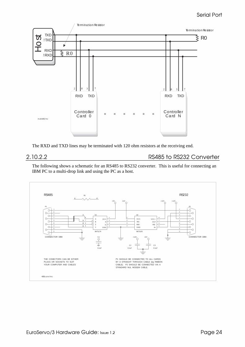
�����"�-���
�������������� ���������)������ ��� -�����3
TXD!TXD
RXD!RXD
RXD TXD
R0
R0
2 8 3 7 2 8 3 7
ControllerCard 0
mult485/mc
TerminationResistor
TerminationResistor
Ho
st
RXD TXD
ControllerCard N
The RXD and TXD lines may be terminated with 120 ohm resistors at the receiving end.
���;����� ��378������������������
The following shows a schematic for an RS485 to RS232 converter. This is useful for connecting anIBM PC to a multi-drop link and using the PC as a host.
RS232R1
A A’
RS485
5
9
4
8
3
7
2
6
1
P1
CONNECTOR DB9
1
2
3
VCC
R
D
GND4
A8
B7
Z6
Y5
U1
SN75179
A
A’
B’
-12V+5V
VCC-1
TXD2
RXD3
GND4
8
7
6
VCC+
OUT
RTC
IN5
U2
SN75155
+12V +12V
5
9
4
8
3
7
2
6
1
P2
CONNECTOR DB9-12V+12V
C2
0.1uF
C3
0.1uF
C1
0.1uF
B
THE CONECTORS CAN BE EITHERPLUGS OR SOCKETS TO SUITYOUR COMPUTER AND CABLES
P1 SHOULD BE CONNECTED TO ALL CARDSBY A STRAIGHT THROUGH CABLE (eg RIBBONCABLE). P2 SHOULD BE CONNECTED VIA ASTANDARD NUL MODEM CABLE.
485conv/mc

����������������
�������������� ���������)������ ��� -�����8
�� ����������������
The option card header (50-way IDC) allows the controller to access additional peripherals asdiscussed in section 1.3 to give additional functionality which is not part of the controller. Thissection describes the option card header in more detail.
The header interface consists of the Data Bus part of the Address bus some control signals and somepower rails. All of the high speed signals are separated by ground lines to reduce any cross-talk orinterference.
��� -���&�����!���
Data bus bit 0 AD0 1 � � 2 GND 0VData bus bit 1 AD1 3 � � 4 GND 0VData bus bit 2 AD1 5 � � 6 GND 0VData bus bit 3 AD1 7 � � 8 GND 0VData bus bit 4 AD1 9 � � 10 GND 0VData bus bit 5 AD1 11 � � 12 GND 0VData bus bit 6 AD1 13 � � 14 GND 0VData bus bit 7 AD1 15 � � 16 GND 0V
Address Latch Enable ALE 17 � � 18 GND 0VRead Strobe !RD 19 � � 20 GND 0VWrite Strobe !WR 21 � � 22 GND 0VAddress bit 0 MA0 23 � � 24 GND 0VAddress bit 1 MA1 25 � � 26 GND 0VAddress bit 2 MA2 27 � � 28 GND 0VAddress bit 3 MA3 29 � � 30 GND 0VAddress bit 4 MA4 31 � � 32 GND 0VAddress bit 5 MA5 33 � � 34 GND 0V
Option Card Select !OCS 35 � � 36 EXTINT External InterruptReset Out !RSTOUT 37 � � 38 !RSTIN Reset InputError In ERRIN 39 � � 40 ERROR Error output
0V GND 41 � � 42 Vcc +5V+5V Vcc 43 � � 44 Vcc +5V0V GND 45 � � 46 +12V +12V
+12V +12V 47 � � 48 GND 0V-12V -12V 49 � � 50 -12V -12V
����� �����"�5�����������
��� �� �����"���
Data Bus These signals are bidirectionally buffered connections to the processors’multiplexed data/address bus and are used to convey data to and from theoption cards.
ALE This signal allows the use of peripherals which need to connect to amultiplexed bus and demultiplex it internally. (Currently unused)
Read/Write These signals are buffered connections to the processor read and write pins,they are used as normal to indicate the direction of data flow and when datais available on the bus. Read is also used to set the direction of the data busbuffers on the controller and the option cards.
Address Bus These signals are buffered connections to the processor address bus. Theyare used, with OCS to determine which card and then which location on thecard is accessed. Bits 5 and 4 determine which card, giving a maximum of 4

����������������
�������������� ���������)������ ��� -�����%
��� �� �����"���
cards. And bits 3-0 are used on each card to give a maximum of 16 bytesper card, 64 bytes in total.
OCS This option card select signal indicates when access to one of the optioncards occurs.
EXTINT This signal is an open drain common interrupt signal from all option cardsfor any cards that require it. (Currently unused)
RSTOUT This signal indicates when the processor or voltage monitor has caused asystem reset. Any peripherals with hardware reset inputs are connected tothis line.
RSTIN Pulling this line low will cause a system reset. (Currently unused)ERRIN This signal is connected in paralell with the standard error in input.ERROR This signal is connected directly to the controller error output.
Power Rails These are connected directly to the controller rails.
��� -����������
A prototyping board is available, for those who want to design their own option cards, which consistsof:
� a connector
� data buffer
� PAL socket
� links for board number (0-3) selection
� a wire wrapping area
� space for a DIN41612 B,C,D or F connector

<����������5���"��������
�������������� ���������)������ ��� -�����9
3�� <��=���������5���"��������
This header allows easy connection of the operator panel, but it can also be used to connect customersown Man Machine Interfaces.
The keyboard connection arrangement is arranged so that an N x M keyboard can be connected with asingle continuos connector. Any matrix from 1x1 upto 8x8 can be read. The matrix does not have tobe a single keypad, it could consist of more than one keypad or a keypad and a series of push buttons.
The display must conform to the format used by Hitachi (most do) and any size up to 20 characters by4 lines can be written to. However, devices other than 20 x 4 will need care in using as they are notexplicitly supported, and some areas can be written to but will not be displayed.
3��� 3('���������-���&������!���
Keyboard Input 7 KIN7 1 � � 2 GND GroundKeyboard Input 6 KIN6 3 � � 4 Vcc +5vKeyboard Input 5 KIN5 5 � � 6 VO Contrast VoltageKeyboard Input 4 KIN4 7 � � 8 RS Regiser SelectKeyboard Input 3 KIN3 9 � � 10 GND Ground (R/W)Keyboard Input 2 KIN2 11 � � 12 E1 Timing signalKeyboard Input 1 KIN1 13 � � 14 SOUT0 Display Data bit 0Keyboard Input 0 KIN0 15 � � 16 SOUT1 Display Data bit 1
Keyboard Output 0 KOUT0 17 � � 18 SOUT2 Display Data bit 2Keyboard Output 1 KOUT1 19 � � 20 SOUT3 Display Data bit 3Keyboard Output 2 KOUT2 21 � � 22 SOUT4 Display Data bit 4Keyboard Output 3 KOUT3 23 � � 24 SOUT5 Display Data bit 5Keyboard Output 4 KOUT4 25 � � 26 SOUT6 Display Data bit 6Keyboard Output 5 KOUT5 27 � � 28 SOUT7 Display Data bit 7Keyboard Output 6 KOUT6 29 � � 30 Vcc +5VKeyboard Output 7 KOUT7 31 � � 32 RED Positive Buzzer con.
Negative Buzzer con. BLACK 33 � � 34 BLUE Buzzer Feedback
3����� �����"�5�����������
��� �� �����"���
Keyboard Inputs (Rows) The controller reads these lines to determine if any of theswitches on the current column are closed.
Keyboard Outputs(Columns)
These lines are pulled low one at a time.
Display Data Bus These signals pass data to the display deviceRS This signal differentiates between the data and control registers
in the display device.GND(R/W) This is the display read/write signal, it is held permanently at 0V
(write).E1 This signal is the timing signal for data transfer.VO This voltage controls the contrast of the display and can be
adjusted over the range -12V to +5V.Buzzer connections These signals connect to a self resonating Pizo sounder unit.
The drive for this is built in to the controller.

�����&������
�������������� ���������)������ ��� -�����7
8�� �����&������
Up to 16 controllers can be connected together over a multi-drop RS485 link for host control.
Host Computer
RS485 Multi-drop link
Up to 16 controllers on multi-drop link
multi/mc/0392
Each card on the link is distinguished by a unique address set by a 4 bit DIP switch located next to theprocessor.
On power up, the controller will show the address number on the LED status for about 1 second. TheDIP switch value can be read through MINT using the CARD keyword.
If the controller is used in a stand-alone system, the card address should be set to address 0.
�� � ��������
� � � �
������� ���
� � � � � �
� � � � � �
� � � � � �
� � � � � �
� � � � � �
� � � � � �
� � � � � �
� � � � � �
� � � � � �
� � � � � �
� � � � �� �
� � � � ��
� � � � �� !
� � � � �� �
� � � � �� �
� � � � �� "
�� ������� 2������
�#���$
3
2
1
0
ON OFF
(1) (0)
Bit
DIP/MC

������""���2��:�"���
�������������� ���������)������ ��� -�����$
%�� /���������""���2��:�"���������������
esback/mc
+12 -12 +5 G UP UG
Encoder 0
Encoder 1
Encoder 2
1 2 3 4 5 6 70 UG UG
Sc D0 Ag D1 Ag D2 Ag DA Ag Sc
3+ 3- EI E1 E2 E3
Earth Stud
1 2 3 4 5 6 70 UP UP
H0 L0 H1 L1 H2 L2 ST RSUP UP
1+ 1- 2+ 2-
PI DI AC FI
INO
UT
Hom
e/Li
mit
AN
A-O
UT
AN
A/E
RR
Pw
r/M
isc
Con
trol
ler
Ser ial
Pwr connector on underside
4������3��)�/���������""���2��:�"���
Your backplane, figure 4.1, has been designed to provide easy connection between the controller andyour application signals. All signals with the exception of the encoders and RS232/485 are connectedto via six removable ten way connectors. Encoders and RS232/485 are connected to via nine pin Dtype connectors.
Connections to the backplane are as follows. For a full description of the function of each signal referto section 2.

������""���2��:�"���
�������������� ���������)������ ��� -����;
%��� 5�����"� ������)� ,/
��� ��������
� :�;���� ���6��� /�� �
/��
� /�� �
� /�� �
0 /�� 0
/��
% /�� %
8 /�� 8
19 1��� ;����� ������ �����������
19
All of the outputs have a flyback diode which is connected internally. This allows the use ofinductive loads without the need for external diodes.
%��� 5�����"�������)��6
��� ��������
� :�;���� ��6��� /�� �
/��
� /�� �
� /�� �
0 /�� 0
/��
% /�� %
8 /�� 8
15 1��� 6���� ����������
15
%�� .��#�.�/
��� ��������
+� +��� '�6�� �
&� &���� '�6�� �
+ +��� '�6��
& &���� '�6��
+� +��� '�6�� �
&� &���� '�6�� �
2( 2��6 '�6��
�2 ����� #��� '�6��
15 1��� 6���� ����������
15
Note: The limit and stop inputs must be connected to UP if not used, for the system tooperate correctly.

������""���2��:�"���
�������������� ���������)������ ��� -�����
%�3� ������5����������������)�&6&( ,/
��� ��������
2# #�/�� ������
:� :����� ,��6�� �
<9 <����;�� 9�����
: :����� ,��6��
<9 <����;�� 9�����
:� :����� ,��6�� �
<9 <����;�� 9�����
:< <�.������ :<# ���6��
<9 <����;�� 9�����
2# #�/�� 2�����
%�8� &��"���������������������)�&6&����
��� ��������
4 <����;�� '�6�� )������������ 4��*
� <����;�� '�6�� )������������ ���*
�4 <����;�� '�6�� �)������������ 4��*
�� <����;�� '�6�� �)������������ ���*
�4 <����;�� '�6�� �)������������ 4��*
�� <����;�� '�6�� �)������������ ���*
-' -���� '�6��
- -���� ,��6�� ������
-� -���� ,��6�� �������� �6��
-� -���� ,��6�� �������� ������
%�%� -� ��)�-'��.���
The Fast Interrupt and Pulse input have fast response times and will capture spurious voltage spikes ifcare is not taken over cable connections. Individually screened cables should be used to connect tothese signals, and the neighbouring Gnd connection may be used to earth the respective screen.
��� ��������
4� 4�3 6���� ��66�� ��6��
�� ��3 6���� ��66�� ��6��
4 43 6���� ��66�� ��6��
9 :�;���� 9�����
15 1��� 6���� ��66�� ��6��
19 1��� ;����� ��66�� ��6��
5' 5���� ��6��
:' :�������� '�6��
�# ����� #������ '�6��
D' D��� '������6� '�6��

������""���2��:�"���
�������������� ���������)������ ��� -�����
%�9� �������������������
The encoder inputs are brought out onto 9 pin 'D' type female sockets. The encoder should be wiredto a 9 pin 'D' male plug.
5 4 3 2 1o o o o o
o o o o9 8 7 6
CHA SCRN !CHB INDEX +5V
!CHA CHB GND !INDEXencoder/mc
��� �� �� ��� ��� � �������� ����
43 � 5���� �� -������ ,��6��
� '�:-B � '���. ���F '�6��
� C#+A � #������ A #��6������ '�6��
0 2#�� � #�/�� 2����� '�6��
#+< � #������ < '�6��
% C'�:-B � '���. #��6������ '�6��
8 9�: � 2�;��� 9�����
7 #+A � #������ A '�6��
$ C#+< � #������ < #��6������ '�6��
%�7� ����������
This connection should be used as the main earth point for your controller. It should be connected toa low impedance star earth point within the system.
%�$� 3�$ �����378
The RS232/485 port available on the front of the card is duplicated on the backplane.

����1
2
26� ) �-
2 ������ � "���) �') ��
� ������ ���� �) �+
����� ����� ) �+
���������� �"��) �'
2 ������ ���"���) �-) ��
��� ���� �����) ��
2�7����� 2� ���"��) ��
8
8���"�� �) �9
� ������ � "���) ��
� ������ ���"���) ��
������� � "���) �1
������� ���"���) �1
� ����� �� ����� �) ��
����� � "��) ��
����� ���"��) ��
(��� � �����"�) ��
$��� � "���) �1
����� � "���) �1
"�#�� ��""��) ��
"���� (����#��) ��
����� � "��) �1
���" � "��) �1
8������ 8���4�") �:
�
����� �����
��� ����� � �) �+
���� �������) �3
�%247) �3
�%847) �3
�� �����
&� 9-4#�� �� �����) 3
�� ������� "�#��
��� "�#�� ��""��) ��
2�) �-
��� ��;������� ) �1
����� �) ��
����� ������) ��
��� � ������ �� $��� � "���) ��
�<2� 47) �-
6� ) �:
������ � "���) ��
����"�� � �� ����� ) �1
&� ���#���) ��
������� � "��) ��
������ ���"���) ��
����"�� � �� ����� ) �1
����� ����") �') �1
���������� �"��) �'
.,5 ���#���) ��) �'
&� �� �����) 3
"� 4���) 3
��� �� ����) 3
���� ����") �'
&*4&�) �+
4��"� �� �����) ��) ��
�
����$) ��
����$ ����) ��
������ �� ���") �9
� �����) �+) �-) �3) �9) ��
"� ���) ��
����� � "��) �1
����"�� � �� ����� ) ��
����� ���"��) �9
����"�� � �� ����� ) ��
�$� �� � �� �� �() �9
(�� ��� #��$ ����2�"��) �9
(�� ��� #��$ ����2�"�3) �9
�**.*4&�) �1
����2�"��) �:
����2�"�3) �:
�7"� ��� 8�����) �) �+
�
���� � �����"�) �1
����"�� � �� ����� ) ��
�2�54&�5) �1
����#��� ."��� �) '
6
6� ���� &�.) ��
� ������ � "���) �'
6��� � "��� �����) �:
%
%� ��$��� �
��� ������ "���) ��
%���#��� �����) �1
%.<�) ��
%��� � "���) ��
����"�� � �� ����� �) �1
����� � ����� �( � <&�5) ��
%.<�47) ��
%��� �
��� ����� �) ��
&
& =47) �3
& "���
��� ������ � "���
>
>������� � � ��"��� %�����) �:
!
!� ������ ���"���) ��) �9
!&<&5) ��
!���� �����) ��
!���� � "���) ��
����"�� � �� ����� �) �1

����1
����) ��
����� � ����� �( � <&�5) ��
���� �� � �7��) ��
��� � �� $��� �#���$��) ��
!&<&547) ��
<
<���� "�������) �-
<����4���") ��) �3
����� � ���� �������) �3
�
�����) ��
.
."������ "� ��) �:
."��� ���� $�����) �+
."��4�������� ����"�� �) ��
.��"���
��� ������� ���"���) �'
�
�� 4���
&� �� �����) 3
��#��) �:
��#�� ��""��) �:
����"�� � �� ����� �) ��
����� (����#��) �+
����"�� � �� ����� �) ��
(����#� � � � �����) �+
�,!��4&�) �+
*
*2<
��� 8������ 8���4�") �:
*�����) �'
*����) �1
����"�� � �� ����� ) �1
*���� � "��) �1
*���54��5*) �+
*����
��� ������ "���) ��
*�����'3+) ��
*�'3+
��� ������ "���) ��
*�'3+ �� *���� �� ������) �'
�
����� � �) �+) �:
��*�) �-
������ "���
�� (�������� ) ��
�� ���� � �� &8< ��) ��
$� ��$��� �) ��
*����) ��) �9configuration, 21connector pinout, 21*�'3+) ��) ��) �9
connector pinout, 22multi-drop, 22
����� ���") �-
����� ������
���"��) �-
����� ���"���) �-) ��
����� � ����� "�������) �-
��� �� ����) 3
���" � "��) �9
����"�� � �� ����� ) �1
����� � ����� �( � <&�5) �9
�5.��?) �9
��""�� ��������) �:
��� ���� ��#�� ��""��) ��
�#���$��) ��
������ ����
����� � ����� "�������) �-
5
5���� ��
��� ������ "���) ��
5���� � "��) �+
,
, ��������� &�.
��� ������ � "���) ��
��� ������ ���"���) ��
,�*4&�47) ��
,�*4.,54�.<) �'
,�*4.,547) �'


Ref: MN00XXX-000;m:\user manuals\eurosystem family\utilities\cterm\i3_0 latest release\ctmuwd.doc/ZZ/XX97
cTERM and MINT™ Utilitiesfor Windows and DOS
Issue:3.0
Copyright Baldor Optimised Control Ltd 1997.
All rights reserved.
This manual is copyrighted and all rights are reserved. This document may not, in whole or in part,be copied or reproduced in any form without the prior written consent of Baldor Optimised Control.
Baldor Optimised Control makes no representations or warranties with respect to the contents hereofand specifically disclaims any implied warranties of fitness for any particular purpose. Theinformation in this document is subject to change without notice. Baldor Optimised Control assumesno responsibility for any errors that may appear in this document.
MINT™ is a registered trademark of Baldor Optimised Control Ltd.
Baldor Optimised Control Ltd.178-180 Hotwell RoadBristolBS8 4RPU.K.Tel: (+44) (117) 987 3100FAX: (+44) (117) 987 3101BBS: (+44) (117) 987 3102
Technical SupportE-mail: [email protected]

Manual Revision History
Issue Date Reference Comments
1.0 Mar 92 MN00106-001 First release1.01 n/a MN00106-0022.0 Mar 96 MN00106-003 Re-formatted for clarity
Added section for cTERM for Windows2.01 Apr 96 MN00106-004 Added section for Macro keys in cTERM for
DOS3.0 Aug 97 MN00106-005 Correct for cTERM for Windows v3.0

Contents
Page i
1. Introduction ............................................................................. 11.1 cTERM....................................................................................................1
2. MINT Programmer’s Toolkit ..................................................... 22.1 Selecting a Controller & COM Port ...................................................2
2.2 The Main Toolbar .................................................................................3
2.3 Terminal.................................................................................................4
2.4 Editor .....................................................................................................5
2.5 The Comms Window...........................................................................5
2.6 Project Files...........................................................................................6
2.7 Capture/Graphing..............................................................................7
2.8 Update..................................................................................................9
2.9 Macros ..................................................................................................9
2.10 Squash...............................................................................................10
3. cTERM for DOS v2.1 ............................................................... 133.1 cTERM Options ...................................................................................13
3.1.1 /c: No CRC......................................................................................................14
3.1.2 /comX: Select COM2.....................................................................................14
3.1.3 /d: Load a defaults file...................................................................................14
3.1.4 /m: Mono screen ............................................................................................14
3.1.5 /l: Load (download) file .................................................................................15
3.1.6 /s: Save (upload) file ......................................................................................15
3.2 Filenames............................................................................................17
3.3 cTERM Menu Structure......................................................................173.3.1 File Menu .........................................................................................................18
3.3.2 Options Menu .................................................................................................19
3.3.3 Terminal ...........................................................................................................20
3.3.4 Comms Menu .................................................................................................20
3.3.5 MINT328............................................................................................................22
3.3.6 Communications Window .............................................................................25

Contents
Page ii
3.4 Log Menu ...........................................................................................26
3.5 Macro/Quick Keys.............................................................................26
4. Function Key Reference for cTERM for DOS....................... 28
5. steTERM for DOS .................................................................... 295.1 Dual Port RAM....................................................................................29
6. DOS Command Line Utilities ................................................ 306.1 LINES: Program Line Numbers ..........................................................30
6.2 SQUASH: MINT Source Code Squasher...........................................316.2.1 Options ............................................................................................................32
6.2.2 Keywords .........................................................................................................36
6.2.3 SQUASH Examples ..........................................................................................36

Introduction
cTERM and MINT™ Utilities: Issue 3.0 Page 1
1. IntroductionThis manual covers the DOS and Windows based utilities and source code contained on the encloseddisks for the MINT™ based motion control products.
1.1 cTERM
cTERM is a terminal emulator for the MINT™ programming language with the following features:
ä File upload and download.ä Full screen programming editor in cTERM for Windows. cTERM for DOS allows any external editor
to be called.ä VT100 compatible terminal screen.ä Support for the MINT Host Computer Communications Protocol.ä cTERM for Windows support the data capture facility of esMINT v2.67 for system tuning. Axis
velocity or following information can be displayed on a graph.ä cTERM for Windows supports the MINT code squashing utility and can be setup to squash code on
download. cTERM for DOS supports code squashing through the use of a DOS utility, SQUASH.cTERM is available both for DOS and Microsoft Windows on the enclosed disks.

cTERM for Windows
cTERM and MINT™ Utilities: Issue 3.0 Page 2
2. MINT Programmer’s ToolkitThe MINT Programmer’s Toolkit is a set of PC applications and examples for use with SmartMove. Themain component of the MINT Programmer’s Toolkit is cTERM for Windows.
Before starting, cTERM must first be installed on the PC. Insert disk 1 into the floppy drive.
If you are running Windows 95:
1. Select Start and Run2. Type A:\SETUP and follow the on screen instructions.3. cTERM can be selected from the MINT Programmer’s Toolkit group.If you are running Window 3.1:
1. Select Run from the Program Manager2. Type A:\SETUP and follow the on screen instructions.3. cTERM can be selected from the MINT Programmer’s Toolkit group.
2.1 Selecting a Controller & COM Port
The first time cTERM for Windows is used it will be configured for a EuroSystem (or member of theEuroSystem family i.e. SmartMove, EuroStep, EuroServo) on COM1. To specify a different controller,select ‘Controller’ from the ‘Setup’ menu.
The controller dialog box (select ‘Controller’ from the ‘Setup’ menu) allows selection of:

cTERM for Windows
cTERM and MINT™ Utilities: Issue 3.0 Page 3
ä Controller Type: EuroSystem Family, NextMove/BX or ServoNode 34, 50 or 51.ä RS232 or RS485: Select RS485 if you are using a multi-drop RS485 system. Note that if you are
using RS485 RTS/CTS will have no effect and should not be relied on to provide hardwarehandshaking.
ä Address (RS485 only): If a multi drop system is being used, the controllers address should be enteredhere.
Use RTS/CTS: In most cases RTS/CTS should be left on except:1. When using a ServoNode 50. These do not support RTS/CTS, so cTERM for Windows will
automatically clear the checkbox when you select ServoNode 50.2. When using a NextMove/BX with MINT version earlier than 3.8.3. If there is a problem updating the firmware with ServoNode 34 or 51. A problem has been found with
some RTS/CTS on some PCs that only shows while operating at the higher speeds involved inupdating the firmware.
4. If you are using RS485 RTS/CTS will have no effect. No hardware handshaking is available onRS485.
The Setup COM Port dialog (select ‘COM Port’ from the ‘Setup’ menu) allows the serial port numberand serial port speed to be specified. It is generally recommended that the highest baud rate supported bythe controller is selected. i.e.:
ä 19200 on the EuroSystem family of controllers running MINT v2.67 on higher (see the BAUDkeyword in the MINT Programming Guide or MINT for NextMove Keyword Reference Guide).
ä 9600 on the EuroSystem family of controllers running MINT version less than 2.67.ä 9600 on ServoNode 50.ä 38400 on NextMove BX (RS232) , 19200 on NextMove BX (RS485).
2.2 The Main Toolbar
Many of the tools in cTERM for Windows can be launched from the main toolbar. All tools aredescribed in greater detail later in the manual.
Download File: if an editor is selected, the editor file will be downloaded. Otherwise a dialog box willprompt for the file to download.
Upload File: if an editor is selected, the file will be uploaded to that editor. If an editor does not havethe focus, a dialog will prompt to upload to an open editor, create a new editor to upload to, or save tofile.
Send MINT ‘Run’ command.
Send ‘Comms abort’ and MINT ‘Break’ ( Ctrl-E ) command.
Terminal: communicate with the MINT command line.
MINT Comms: communicate with a running MINT program using the protected mode comms array.
to Execute macros 1 through to 10.

cTERM for Windows
cTERM and MINT™ Utilities: Issue 3.0 Page 4
2.3 Terminal
For the Terminal Window select ‘Terminal’ from the ‘Tools’ menu or on the toolbar.
The Terminal window provides access to the MINT command line. The terminal can be resized up to amaximum size of fifty lines by eighty columns either by dragging the border or selecting ‘Terminal’ fromthe ‘Setup’ menu.

cTERM for Windows
cTERM and MINT™ Utilities: Issue 3.0 Page 5
2.4 Editor
For the editor, select ‘New File’ + type from ‘File’ menuor:
Select ‘Open File’ + type from ‘File’ menuor:
Select ‘Upload File + type (to editor)’ from the ‘File’ menu.or:
Press to load a file into an editor from the controller.
An editor with cut/paste and search/replace facilities is available from the ‘File’ menu. Either a new filecan be selected or an existing file opened. Separate editors are supported for both the MINT programand MINT configuration files.
The standard Windows Cut, Copy and Paste functions are available from the toolbar as well as the Editmenu. Other functions for the editor include:
ä Ability to change the font settings from the Setup/Font menu.ä Downloading the files to the controller through the use of the download icon on the button bar. Using
the Setup/Squash menu, files can be compressed on download. Alternatively, selecting Edit/Squashwill squash the current editor file to a new file. Full details of squash can be found in section 2.10.
ä Uploading the files from the controller into the current menu. cTERM will automatically upload thecorrect file from the controller depending upon which editor window is open.
ä Ability for MINT files to be dragged from the Program Manager / Explorer onto the cTERM desktop.This will automatically open the editor.
ä Printing from the editor using the Print icon on the tool bar. The file is printed to the currentlyinstalled Windows printer.
2.5 The Comms Window
For the Terminal Window select ‘Comms Window’ from the ‘Comms’ menu or on the toolbar.

cTERM for Windows
cTERM and MINT™ Utilities: Issue 3.0 Page 6
The MINT Comms Protocol is supported through the use of the Comms Window, allowing thedebugging of a MINT program using the comms protocol. The Comms Protocol is discussed in theMINT Programming Guide.
Locations are added using the button, and removed using the button. The Address field is thecomms array index and the Description is free form text. The data within the Value field is then updatedusing a timer.
It is possible to change a value of a comms location by clicking on the value field and editing it in theedit field. Click the button to update the value and write it back to the controller. Note that Enterwill not write back the value. The button can be used to cancel the value.
To rearrange the lines in the grid, select the address of the comms location to move and use the buttons to move it.
Notes:
1. The Comms Window polls the controller on a regular basis. This will slow the MINT programrunning on the controller as it will have to spend a high percentage of its time processing the commsrequests. The more comms locations are put in the window, the slower MINT will execute.
2. To pause the Comms Window select the Terminal Window. Only one of the Terminal Window andComms window can be active at any one time, so selecting one disables the other.
3. For a multi-drop RS485 system, the card address for individual controllers is selected using eitherComms Address from the Comms menu, or Controller from the Setup menu.
2.6 Project Files
cTERM for Windows uses project files to record the following information.
ä Open editors.ä COM port settings.ä Locations displayed in the Comms window.ä Terminal settings.This is particularly useful if many elements have been added to the Comms Window. To save a projectselect the File/Save Desktop As menu option. The information is saved to a file with a .CTW extension.Once saved, the .CTW file can be added to the program manager as an icon in Windows 3.1 or to theTaskbar in Win95. Selecting the icon will start cTERM for Windows with the desktop settings. This canbe used to create, for example, one icon for each COM port. There are several ways to open a desktop:
ä If cTERM for Windows is started normally, the most recent desktop is used.ä Create an icon for the desktop (as above).ä Pass the name of the desktop file to cTERM for Windows as a parameter e.g. Command Line : c:\ctwin\ctwin.exe c:\ctwin\com1.ctw

cTERM for Windows
cTERM and MINT™ Utilities: Issue 3.0 Page 7
ä Drag the desktop file from the File Manager/Windows Explorer and drop it on to cTERM forWindows.
2.7 Capture/Graphing
For Capture select ‘Capture’ from the ‘Tools’ menu.cTERM for Windows allows a move to be set up and plotted in order to assist in servo tuning. This usesthe CAPTURE keyword implemented in esMINT v2.65 or higher. As there can be a large amount ofdata to be transferred it is recommended that the MINT BAUD keyword is used to set the baud rate to19200 before using the capture facility.
To have cTERM for Windows set up and perform a move, select the required move parameters in theCapture Parameters dialog. It is possible to have cTERM for Windows create a new configuration filefor you by selecting the ‘Create New Configuration File’ radio-button, or the current gains can be usedby selecting the ‘Use Existing Gains / Configuration File’ radio-button. With the ‘Use Existing ..’ optionselected, the configuration file will not be modified.
It is also possible to have cTERM for Windows load and plot on a graph custom data. To do this
ä Store the data on the controller in an array called data.ä Create a variable on the controller called NUMPOINTS which holds the number of points to plot.ä Press the 'Custom' button to begin loading the data.
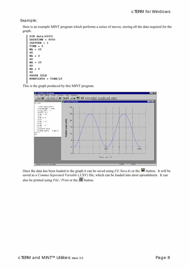
cTERM for Windows
cTERM and MINT™ Utilities: Issue 3.0 Page 8
Example:
Here is an example MINT program which performs a series of moves, storing all the data required for thegraph.
DIM data(4000)DATATIME = 8000CAPTURE = 3TIME = 0MA = 25GOMA = 0GOMA = 25GOMA = 0GOPAUSE IDLENUMPOINTS = TIME/LT
This is the graph produced by this MINT program.
Once the data has been loaded to the graph it can be saved using Fil /SaveAs or the button. It will besaved as a Comma Seperated Variable (.CSV) file, which can be loaded into most spreadsheets. It canalso be printed using File / Print or the button.

cTERM for Windows
cTERM and MINT™ Utilities: Issue 3.0 Page 9
2.8 Update
For Update select ‘Update’ from the ‘Tools’ menu.Update allows a new version of MINT to be loaded onto ServoNode or NextMove/BX via the controllersRS232 port. It should only be used when Baldor Optimised Control or a distributor have provided a newversion of MINT, or custom firmware has been written for NextMove/BX using the MINT InterfaceLibrary.
To update the firmware.
ä Select 'Update' from the 'Tools’ menu.ä Select the file to load onto the controller. This will usually be MINT.HEX for ServoNode and
MINT.H02 for NextMove/BX.ä cTERM for Windows will display a progress screen. When it displays “Waiting for controller to
power-up”, remove the power to the controller for ten seconds and power it up again.
ä The progress screen should display "Controller is erasing flash". If it hasn't displayed this messagewithin ten seconds, power cycle the controller again.
- IMPORTANT -Once cTERM has reached the “Controller is erasing flash” stage do NOT remove the powerto a ServoNode 50 until update has completed. Use the cancel button if you have to stop theupdate. In the case of power being removed to the PC, or the PC crashing, remove the serial
cable from the controller and wait one minute to allow the controller to timeout beforetrying again.
ä Once the controller has erased its flash, the progress screen will display the percentage of thefirmware downloaded. It can take up to five minutes to complete, particularly on slower PCs.
2.9 Macros
To edit a macro, select ‘Macros’ from the ‘Setup’ menu.Ten macro buttons are located on the right hand side of the cTERM for Windows toolbar. Each macrowill allow a text string to be sent to the controller. Editing these macros is performed in the ‘SetupMacros’ dialog (select ‘Macros’ from the ‘Setup’ menu).
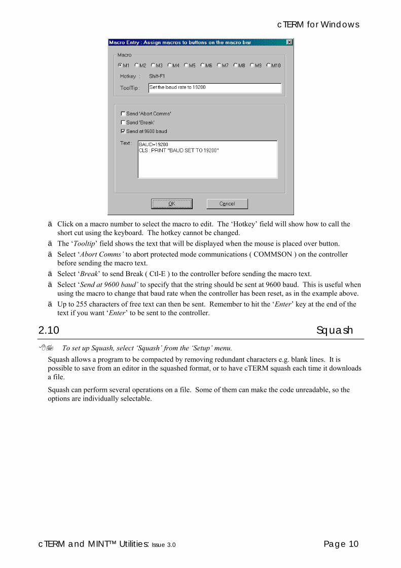
cTERM for Windows
cTERM and MINT™ Utilities: Issue 3.0 Page 10
ä Click on a macro number to select the macro to edit. The ‘Hotkey’ field will show how to call theshort cut using the keyboard. The hotkey cannot be changed.
ä The ‘Tooltip’ field shows the text that will be displayed when the mouse is placed over button.ä Select ‘Abort Comms’ to abort protected mode communications ( COMMSON ) on the controller
before sending the macro text.ä Select ‘Break’ to send Break ( Ctl-E ) to the controller before sending the macro text.ä Select ‘Send at 9600 baud’ to specify that the string should be sent at 9600 baud. This is useful when
using the macro to change that baud rate when the controller has been reset, as in the example above.ä Up to 255 characters of free text can then be sent. Remember to hit the ‘Enter’ key at the end of the
text if you want ‘Enter’ to be sent to the controller.
2.10 Squash
To set up Squash, select ‘Squash’ from the ‘Setup’ menu.Squash allows a program to be compacted by removing redundant characters e.g. blank lines. It ispossible to save from an editor in the squashed format, or to have cTERM squash each time it downloadsa file.
Squash can perform several operations on a file. Some of them can make the code unreadable, so theoptions are individually selectable.

cTERM for Windows
cTERM and MINT™ Utilities: Issue 3.0 Page 11
ä ‘Remove Inentation’ removes spaces from the start of lines.ä ‘Remove Spaces’ removes any unnecessary spaces other than at the start of a line.ä ‘Remove REMs’ removes all REM statements.ä ‘Remove Blank Lines’ removes any blank lines.ä ‘Evaluate Constants’ replaces any MINT constants with their numeric values (for example: replace
_servo with 1).ä ‘Abbreviate keywords’ replaces any longhand MINT keywords with their two or three letter forms.ä ‘Rename Variables’ replaces any user variable names with single letter variable names. It will replace
the first variable it finds with ‘a’, the second with ‘b’ and so on. It is possible to have cTERM forWindows create a file of the variables it has renamed, and what it has renamed them with (see later).
ä ‘Optimise Axis Strings’ will replace any single axis statements in the square bracket form with the dotform. For example: MA[0] will be squashed to MA.0
The ‘Advanced’ tab allows further options to be specified.
ä ‘Squash on Download’ will squash each file as it is downloaded. This allows the file to be edited inthe editor in its full ‘readable’ form, but will download a compact version of the code.

cTERM for Windows
cTERM and MINT™ Utilities: Issue 3.0 Page 12
ä ‘Create Cross Reference File Of Renamed Variables’ create a file specifying which variables havebeen replace if the ‘Rename Variables’ option was selected. The file will be stored in the same placeas the program being squashed and will have a .VAR extension.
The ‘Update’ tab is for future implementation.

cTERM for DOS
cTERM and MINT™ Utilities: Issue 3.0 Page 13
3. cTERM for DOS v2.1cTERM for DOS version 2.1 is a powerful terminal emulator program supplied specifically for use withthe MINT™ based serial range of controllers. cTERM offers the following features:
ä Automatically sets up the serial port for the controllerä Easy to use 'pop-down' menu structureä File upload and downloadä File upload and download from the DOS command line allowing file upload/download from within
other application programsä Powerful debugging facilities for controller communicationsä Facility to call your favourite program editor from within cTERM. The editor is called with the
relevant filename for editing.To use the utilities, you require the following:
ä IBM compatible PC with 3.5" disketteä DOS version 2.0 or higherä Serial communication ports COM1 or COM2cTERM is called by simply typing:
CTERM
at the DOS prompt. cTERM can also be called withvarious options, see the section on cTERM Options formore details.
After a period of about 4 seconds, or on pressing a key, youwill be taken direct to the terminal screen. Provided acontroller is connected and powered up, characters typed atthe keyboard should be echoed back to the terminal. IfcTERM cannot communicate with the controller thefollowing error message will be display:
3.1 cTERM Options
cTERM can be called with various options using the following syntax:cTERM [options]
by typing:CTERM /h
a list of the following options will be displayed:/c Do not use the CRC checking on file upload/download/comX Select COMx for communications (1 .. 4)/d Load a defaults file/m Force mono attributes/l Download a file from the DOS prompt/s Upload a file from the DOS prompt

cTERM for DOS
cTERM and MINT™ Utilities: Issue 3.0 Page 14
Example:CTERM /m /com2
will call up cTERM in mono mode and use COM2 for serial communications. Note that cTERM canaccept any number of arguments.
3.1.1 /c: No CRC
Format:CTERM /c
cTERM on file upload and download will automatically add a Cyclic Redundancy Checksum to the endof the file to ensure correct transmission of the files. To suppress the check, use the /c option.
3.1.2 /comX: Select COM2
Format:CTERM /com2
Using the /com2 option, all serial communications will be addressed through communications port 2(COM2). The active communications port (COMx) will be displayed in the bottom right corner of thescreen.
If your PC supports comms ports 3 and 4, the argument /COM3 or /COM4 can be used to select thecomms port.
3.1.3 /d: Load a defaults file
Format:CTERM /d:<filename>
The defaults file is used to store the filenames used in a cTERM session. By default cTERM will loadthe defaults file cTERM.DEF which can be placed anywhere within the DOS path (see your DOS manualfor an explanation of the path). If you require to load a defaults file other than cTERM.DEF, then callcTERM with the /d option as shown in the example:
CTERM /d:xyplot
will load the defaults file xyplot.def. Note that no extension is necessary since cTERM will use theextension .DEF for all default files.
Default files can also be loaded and saved from the Options menu.
3.1.4 /m: Mono screen
Format:CTERM /m
The /m will force cTERM to use monochrome attributes. cTERM will automatically detect amonochrome monitor but many mono LCD displays emulate colour displays. Use the /m option to give amore acceptable display on LCD screens.

cTERM for DOS
cTERM and MINT™ Utilities: Issue 3.0 Page 15
3.1.5 /l: Load (download) file
Format:CTERM /l<buffer>:<filename>
The /l options allows files to be downloaded from the DOS command line without calling up the cTERMterminal screen.
Using the above format, <buffer> is a number relating to one of the following MINT files:
<buffer> File
1 Program file2 Configuration file3 Array data
For example:CTERM /l1:xyplot
will download the file XYPLOT.MNT to the program buffer. Note that the the following defaultextension is attached to the file if no extension is given:
File Extension
Program .MNTConfiguration .CFGArray .ARR
cTERM will display any error message and also return the error as a DOS errorlevel number. Theerrorlevel numbers:
errorlevel Error
0 No error1 Cannot open file or file not found2 Cannot download the file3 Timeout on serial transmission4 Checksum error
Notes:
ä If you require to load a file over serial communications port 2, the /com2 option must be places beforethe /l option as follows:CTERM /com2 /l1:test
ä A utility (including source code), FUD485, is available within the CLIB subdirectory for file uploadand download. FUD485 also includes additional features for aborting program execution, terminatingthe Comms Protocol and re-running the program.
3.1.6 /s: Save (upload) file
Format:CTERM /s<buffer>:<filename>
The /s options allows files to be uploaded from the DOS command line without calling up the cTERMterminal screen.

cTERM for DOS
cTERM and MINT™ Utilities: Issue 3.0 Page 16
Using the above format, <buffer> is a number relating to one of the following MINT files:
<buffer> File
1 Program file2 Configuration file3 Array data
For example:CTERM /s1:xyplot
will upoad the program file to XYPLOT.MNT. Note that the the following default extension is attatchedto the file if no extension is given:
File Extension
Program .MNTConfiguration .CFGArray .ARR
cTERM will display any error message and also return the error as a DOS errorlevel number. Theerrorlevel numbers:
errorlevel Error
0 No error1 Cannot open file or file not found2 Cannot download the file3 Timeout on serial transmission4 Checksum error
Notes:
ä If you require to save a file over serial communications port 2, the /com2 option must be places beforethe /s option as follows:CTERM /com2 /s1:test
ä A utility (including source code), FUD485, is available within the CLIB subdirectory for file uploadand download. FUD485 also includes additional features for aborting program execution, terminatingthe Comms Protocol and re-running the program.

cTERM for DOS
cTERM and MINT™ Utilities: Issue 3.0 Page 17
3.2 Filenames
Where filenames are requested within cTERM, alist of the file in the current directory can becalled up by pressing F2. For example: a programfilename is requested, pressing F2 will display allfiles with a .MNT extension. Pressing Enter onthe filename will automatically enter the nameinto the field and perform the required action.You can also move around a disk's directorystructure. Files prefixed with '\' are directories.Pressing Enter on a directory name will move youdown into the directory. To move up a directory,press Enter on the file '..\' (the parent directory).
The default file extensions are:
Extension File
.MNT MINT Program file.CFG MINT Configuration file.ARR MINT Array data file.PLT HPGL plot file.HPC HPGL configuration file.CMS Comms protocol data file.328 MINT/3.28 data file.DEF cTERM defaults file.LOG cTERM log file
If you require a file that does not use a default file extension, press Shift-F2 instead of F2. This willdisplay all files in the directory.
3.3 cTERM Menu Structure
Pressing F10 from the terminal screen will open up the main menu:
The menu options are:
FILE: Allows upload and downloading of files to the controller. Files can also be editedusing an external editor.
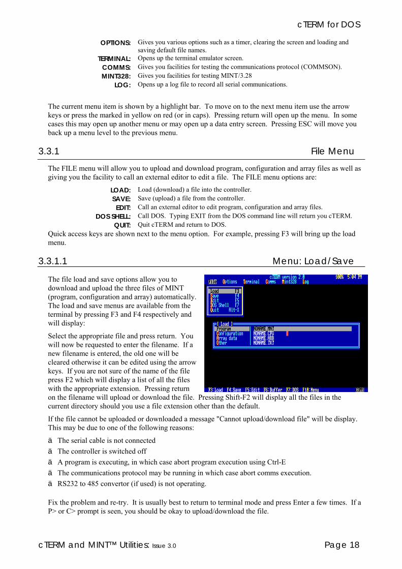
cTERM for DOS
cTERM and MINT™ Utilities: Issue 3.0 Page 18
OPTIONS: Gives you various options such as a timer, clearing the screen and loading andsaving default file names.
TERMINAL: Opens up the terminal emulator screen.COMMS: Gives you facilities for testing the communications protocol (COMMSON).MINT328: Gives you facilities for testing MINT/3.28
LOG: Opens up a log file to record all serial communications.
The current menu item is shown by a highlight bar. To move on to the next menu item use the arrowkeys or press the marked in yellow on red (or in caps). Pressing return will open up the menu. In somecases this may open up another menu or may open up a data entry screen. Pressing ESC will move youback up a menu level to the previous menu.
3.3.1 File Menu
The FILE menu will allow you to upload and download program, configuration and array files as well asgiving you the facility to call an external editor to edit a file. The FILE menu options are:
LOAD: Load (download) a file into the controller.SAVE: Save (upload) a file from the controller.EDIT: Call an external editor to edit program, configuration and array files.
DOS SHELL: Call DOS. Typing EXIT from the DOS command line will return you cTERM.QUIT: Quit cTERM and return to DOS.
Quick access keys are shown next to the menu option. For example, pressing F3 will bring up the loadmenu.
3.3.1.1 Menu: Load/Save
The file load and save options allow you todownload and upload the three files of MINT(program, configuration and array) automatically.The load and save menus are available from theterminal by pressing F3 and F4 respectively andwill display:
Select the appropriate file and press return. Youwill now be requested to enter the filename. If anew filename is entered, the old one will becleared otherwise it can be edited using the arrowkeys. If you are not sure of the name of the filepress F2 which will display a list of all the fileswith the appropriate extension. Pressing returnon the filename will upload or download the file. Pressing Shift-F2 will display all the files in thecurrent directory should you use a file extension other than the default.
If the file cannot be uploaded or downloaded a message "Cannot upload/download file" will be display.This may be due to one of the following reasons:
ä The serial cable is not connectedä The controller is switched offä A program is executing, in which case abort program execution using Ctrl-Eä The communications protocol may be running in which case abort comms execution.ä RS232 to 485 convertor (if used) is not operating.
Fix the problem and re-try. It is usually best to return to terminal mode and press Enter a few times. If aP> or C> prompt is seen, you should be okay to upload/download the file.

cTERM for DOS
cTERM and MINT™ Utilities: Issue 3.0 Page 19
The options Program to Array automatically send the LOAD and SAVE commands and a CRC to thecontroller. If this is not required, use the "Other" option. Loading a "other" file will download the filecontents only. If you request "Save Other", then on returning to the terminal screen, anything transmittedfrom the terminal screen will be saved to the file. This is useful for saving data from an executingprogram. Pressing ESC will close the file.
3.3.1.2 Menu: Edit
cTERM allows you to edit the MINT files bycalling an external editor of your choice.Choosing the edit option (or pressing F5 from theterminal screen) will display:
Selecting any of the file and entering a filenamewill call the editor with the filename given. Theeditor can be changed by moving to the Editoroption and entering a new name. You can thensave this as your default editor by using the SaveDefault menu option within the Options menu andselecting CTERM.DEF as the defaults file. Everytime cTERM is called, the defaults file,CTERM.DEF will be loaded unless anotherdefaults file is requested.
3.3.2 Options Menu
The options menu is:
TIMER: Turns a timer on and off. The timer will time between successive beeps and canbe used to time routines within MINT programs.
CTS: Turns the CTS checking of cTERM on and off.LOCAL ECHO Turns local echo on and off. This is used to HPGL which does not support
echoing. All characters sent to the controller will be displayed in magenta onthe screen.
VT100 Allows VT100 emulation to be turned off.CLEAR SCREEN: Clears the terminal screen and homes the cursor.CLEAR BUFFER: Clears the serial port buffer. On slow machines, cTERM may have trouble
keeping up with large amounts of data over the serial port. This option willallow cTERM's internal serial buffer to be flushed.
SAVE DEFAULTS: Save all filenames to a defaults file.LOAD DEFAULTS: Restore all saved filenames from a defaults file.
3.3.2.1 Using cTERM with HPGL Firmware OptionWhen using HPGL with cTERM, Local Echo should be turned on and VT100 turned off.
3.3.2.2 Menu: TimerThe cTERM timer option allows you to time MINT programs between successive beeps. For example:
BEEPMOVEA = 100 : GO : PAUSE IDLEBEEP
On receiving the first BEEP, the timer start, when the second BEEP is received, the timer will stop andits value in seconds.milliseconds will be displayed to the terminal screen.

cTERM for DOS
cTERM and MINT™ Utilities: Issue 3.0 Page 20
3.3.2.3 Menu: Load/Save DefaultsThe load and save defaults options are used to save the filenames used within cTERM to a file for futurereference. The following filenames are saved to the defaults file:
ä Program (.MNT)ä Configuration (.CFG)ä Array data (.ARR)ä "Other" filenameä Comms protocol data file (.CMS)ä MINT/3.28 data file (.328)ä Log file (.LOG)ä Editor filenamecTERM will load the defaults file, CTERM.DEF, when loaded from DOS. Using the /d option, anotherdefaults file can be loaded. For example:
CTERM /d:keypad1
will load the defaults file KEYPAD1.DEF
3.3.3 Terminal
The terminal option opens up the terminal screen which allows communication with the controller. If,for some reason, there is no communication with the controller, an error message will be displayed.
There are various hot keys available from the terminal window to allow file upload/download etc. Thehot keys are labelled across the bottom of the screen:
F3: Calls up the file download (load) menu. Press ESC to return control to the terminal.F4: Calls up the file upload (save) menu. Press ESC to return control to the terminal.F5: Call up the external editor menu. Control is returned to the editor menu after the editor has been
called. Press ESC to return control to the terminal.F6: Flushes the serial port buffer.F7 Call the DOS Shell. Type EXIT from the DOS command line to return to cTERM
Shift-F8: Aborts MINT Host Computer Communications Protocol.Alt-X: Abort cTERM and return to DOS.
3.3.4 Comms Menu
The comms menu facilitates the testing of the MINT Host Computer Communications Protocol over amulti-drop line and has the following options:
ä Write to a comms addressä Read a comms addressä Abort comms protocolä Send a comms data fileYou are advised to read section 13 in the MINT Programming Guide for details on the MINT HostComputer Communications Protocol.
To aid debugging of a multi-drop comms system, a log file can be opened to record all data going up anddown the serial port. The log file is discussed in a later section.
3.3.4.1 Menu: Comms WriteA data entry window is opened to allow you to enter data to be sent to any one of 16 controllers.

cTERM for DOS
cTERM and MINT™ Utilities: Issue 3.0 Page 21
The parameters are:
Card #: Card number to send data to. Card numbers 10 to 15 are entered as A to F respectively.Comms
Address:The communication address (pigeon hole) to send the data to. Valid address numbersare between 0 and 99.
Data: The data to send. Any valid MINT number is allowed in this field.Max Retry: This determines the maximum number of retries, if data is corrupted or cannot get
through, before giving up.Data Packets: The number of data packets to send. For example, a value of 10 will send a total of 10
data packets to the controller.Delay Time: Determines the delay between sending data packets where 1 represents 1/18th of a
second. This allows you to see what is going on in the communications window.Pressing any key will override the delay and process the next data packet.
When the data has been entered, it is transmitted. All transmission is displayed in the CommunicationsWindow (see later).
3.3.4.2 Menu: Comms ReadA data entry window is opened to allow you to read data from a comms address from any one of 16controllers. The field parameters are:
Card #: Card number to send data to. Card numbers 10 to 15 are entered as A to F respectively.Comms
Address:The communication address (pigeon hole) to send the data to. Valid address numbersare between 0 and 99.
Max Retry: This determines the maximum number of retries, if data is corrupted or cannot getthrough, before giving up.
Data Packets: The number of data packets to send. For example, a value of 10 will send a total of 10data packets to the controller.
Delay Time: Determines the delay between sending data packets where 1 represents 1/18th of asecond. This allows you to see what is going on in the communications window.Pressing any key will override the delay and process the next data packet.
When the data has been entered, it is transmitted. All transmission is displayed in the CommunicationsWindow (see later). The result of the comms address is shown in the communications window.
3.3.4.3 Menu: Abort CommsBefore program execution can be aborted, using Ctrl-E, the communications protocol must be aborted bysending a special data packet. Using the Abort Comms menu option the required data packet will be sentto abort comms.
Note: Comms can be aborted from the terminal screen by pressing Shift-F8.
3.3.4.4 Menu: Load FileDifferent data packets can be created in a special format using a standard text editor. Once created, thesefiles can be transmitted to the controllers using the Load File option. This allows files to be created thatcan send data to more than one controller on a mutli-drop link. The data packets are made up as follows:
cTERM for DOS
cTERM and MINT™ Utilities: Issue 3.0 Page 22
A read data packet is made up as follows:R;<card #>;<comms address>
Example:R;0;10
will read comms address 10 on card 0.
A write data packet is made up as follows:W;<card #>;<comms address>;<data>
Example:W;1;23;1234.5
will write 1234.5 to comms address 23 on card 1.
A comms data file may look like:: Sample file for commsW;0;01;1234.123R;0;01W;0;01;4321.321R;0;01W;0;99;1234.123R;0;99W;0;99;4321.321R;0;99
3.3.5 MINT328
The MINT328 menu facilitates the testing of MINT/3.28 for host computer communications over amulti-drop line and has the following options:
ä Write to a motion keywordä Read a motion keywordä Send a motion commandä Send a data fileYou are advised to read section 13 in the MINT Programming Guide for details on MINT/3.28.
To aid debugging of a multi-drop comms system, a log file can be opened to record all data going up anddown the serial port. The log file is discussed in a later section.
3.3.5.1 Menu: WriteA data entry window is opened to allow you to write data to be a MINT/3.28 keyword to any one of 16controllers.
cTERM for DOS
cTERM and MINT™ Utilities: Issue 3.0 Page 23
The field parameters are:
Card #: Card number to send data to. Card numbers 10 to 15 are entered as A to Frespectively.
Keyword: Two letter abbreviated MINT keyword.Axis: Axis number. This conforms to the MINT/3.28 axis number, for example an axis
number of 3 represents axes 0 and 1.Data: The data to send. Any valid MINT number is allowed in this field. Data to more than
one axis must be seperated by commas. Note that the semi-colon syntax as with MINTin not supported within MINT/3.28
Max Retry: This determines the maximum number of retries, if data is corrupted or cannot getthrough, before giving up.
Data Packets: The number of data packets to send. For example, a value of 10 will send a total of 10data packets to the controller.
Delay Time: Determines the delay between sending data packets where 1 represents 1/18th of asecond. This allows you to see what is going on in the communications window.Pressing any key will override the delay and process the next data packet.
When the data has been entered, it is transmitted. All transmission is displayed in the CommunicationsWindow (see later).

cTERM for DOS
cTERM and MINT™ Utilities: Issue 3.0 Page 24
3.3.5.2 Menu: ReadA data entry window is opened to allow you to read a MINT/3.28 keyword from one of 16 controllers.The field parameters are:
Card #: Card number to send data to. Card numbers 10 to 15 are entered as A to Frespectively.
Keyword: Two letter abbreviated MINT keyword.Axis: Axis number. This conforms to the MINT/3.28 axis number, for example an axis
number of 3 represents axes 0 and 1.Max Retry: This determines the maximum number of retries, if data is corrupted or cannot get
through, before giving up.Data Packets: The number of data packets to send. For example, a value of 10 will send a total of 10
data packets to the controller.Delay Time: Determines the delay between sending data packets where 1 represents 1/18th of a
second. This allows you to see what is going on in the communications window.Pressing any key will override the delay and process the next data packet.
When the data has been entered, it is transmitted. All transmission is displayed in the CommunicationsWindow (see later).
3.3.5.3 Menu: CommandA data entry window is opened to allow you to send a MINT/3.28 command to any one of 16 controllers.The field parameters are:
Card #: Card number to send data to. Card numbers 10 to 15 are entered as A to Frespectively.
Keyword: Two letter abbreviated MINT keyword.Axis: Axis number. This conforms to the MINT/3.28 axis number, for example an axis
number of 3 represents axes 0 and 1.Max Retry: This determines the maximum number of retries, if data is corrupted or cannot get
through, before giving up.Data Packets: The number of data packets to send. For example, a value of 10 will send a total of 10
data packets to the controller.Delay Time: Determines the delay between sending data packets where 1 represents 1/18th of a
second. This allows you to see what is going on in the communications window.Pressing any key will override the delay and process the next data packet.
When the data has been entered, it is transmitted. All transmission is displayed in the CommunicationsWindow (see later).
3.3.5.4 Menu: Load FileDifferent data packets can be created in a special format using a standard text editor to allow a mixture ofread, write and command data packets. Once created, these files can be transmitted to the controllersusing the Load File option. This allows files to be created that can send data to more than one controlleron a mutli-drop link. The data packets are made up as follows:
A read data packet is made up as follows:R;<card #>;<keyword>;<axis>
Example:R;0;PS;1
will read the position of axis 1 on card 0.
A write data packet is made up as follows:W;<card #>;<keyword>;<axes>;<data>
cTERM for DOS
cTERM and MINT™ Utilities: Issue 3.0 Page 25
Example:W;1;VR;3;100,200
will setup a vector relative move on axes 0 and 1 on card 1 with relative coordinates of 100,200. Notethat <axes> is coded, where 3 represents axes 0 and 1. See section 14 in the MINT Programming Guidefor further details.
A command data packet is made up as follows:C;<card #>;<keyword>;<axes>
Example:C;0;ST;0
will stop motion on card 0, axis 0
A MINT/3.28 data file may look like the following:: Sample file for MINT/3.28C;0;RE;6: 2 axes of motion onlyW;0;GN;3;2,2W;0;KV;3;10,10W;0;SF;3;2000,2000W;0;SP;3;20,20W;0;AC;3;750,750W;0;RP;3;2.5,2.5
3.3.6 Communications Window
The communication window is used to display all datapacket transmissions over the serial port. cTERM usescolour to represent various data packets and messages.These are:
Colour Meaning
Yellow Transmitted dataCyan Received DataLight Grey Contents of serial buffer on
flushingWhite Comments (also enclosed in
curly braces)
All ASCII characters below 32 are represented by their control names. For example, if ASCII 6 isreceived, this will be displayed to the screen as "[ACK]". Note that space (ASCII 32) is shown as"[SPC]" within data packets to distinguish it from spaces within messages. Spaces are used to aid claritywhen reading data packets.
It should be noted that before a data packet is transmitted, the serial port buffer is flushed. To aiddebugging, any flushed characters are displayed in the communication window in light grey.
The status window shows the number of data packets sent, the total number of retries and the number ofretries for the current data packet.

cTERM for DOS
cTERM and MINT™ Utilities: Issue 3.0 Page 26
3.4 Log Menu
The Log menu is used to open and close serial communications log files. When a log file is opened, allcommunications over the serial port will be recorded within this log file. For example:
The log file can be used to determine any problem areas within data communications.
Example:{Log file opened March 30, 1992; 9:27 AM}[EOT]00[STX]011234.123[ETX][CAN][ACK][EOT]00[STX]01[ENQ][STX]011234.121[ETX][SUB]{ Result = 1234.121 }[EOT]00[STX]014321.321[ETX][CAN][ACK][EOT]00[STX]01[ENQ][STX]014321.320[ETX][EM]{ Result = 4321.320 }[EOT]00[STX]991234.123[ETX][EM][ACK][EOT]00[STX]99[ENQ][STX]991234.121[ETX][ESC]{ Result = 1234.121 }[EOT]00[STX]994321.321[ETX][EM][ACK][EOT]00[STX]99[ENQ][STX]994321.320[ETX][CAN]{ Result = 4321.320 }
All log entries in curly braces {} are comments placed by cTERM and are not data items. For example,"{ Retry }" is used to tell you that a data packet retry took place. The most common comments are:
{ Retry } Data packet retry{ Timeout } Communications timed out{ Failed } Data packet failed to be successfully transmitted.
All ASCII characters below 32 are represented by their control names. For example, if ASCII 6 isreceived, this will be displayed in the log file as "[ACK]". Note that space (ASCII 32) is shown as"[SPC]" within data packets to distinguish it from spaces within messages.
The log file is closed by using the "Close log file" menu option. The log file can be viewed using the fileedit facility.
3.5 Macro/Quick Keys
Macros can be placed on functions keys whereby a line of textof up to 75 characters in length can be sent to the controller.For example, assume that for machine setup you are interestedin the position and digital input details of the controller.Rather than typing “? POS” and ? “IN” each time, these stringscan be attached to a function key. Pressing the function keywill send the string to the controller for execution.
To define a macro definition, press Alt-M from the terminalwindow. A menu will appear for the 10 function keys.Pressing enter will allow the key definition to be altered or entered. Press Enter to accept the definition.Esc will return you back up a level.

cTERM for DOS
cTERM and MINT™ Utilities: Issue 3.0 Page 27
Backslash (\), is used to force a carriage return and is the same as pressing Enter on the keyboard.Backslash must be given as the final character to force a carriage return.
Once defined, the string is sent to the controller by using the Alt-Function key. For example Alt-F1 maybe defined as:
PRINT POS.0\PRINT POS.1\
This is equivalent to typing:PRINT POS.0PRINT POS.1
Once created, the function key definitions can be saved to a cTERM defaults file by using theOptions/Save Defaults menu.
cTERM for DOS
cTERM and MINT™ Utilities: Issue 3.0 Page 28
4. Function Key Reference for cTERM for DOS
Function Key Function
F2 Gives a directory listing when requested for a fileF3 Call up file download menuF4 Call up file upload menuF5 Call up file edit menu
Shift-F5 Clear the terminal screenF6 Clear the serial port bufferF7 Shell out to the DOS promptF8 Moves through the DPR pages 0 to 2
Ctrl-F8 Allows selective DPR contents to be written to.F9 Pops up a menu for selecting a controller
Ctrl-F9 Toggles the DPR page lock. Pressing Ctrl-F9 will lock the DPR contents until Ctrl-F9 is pressed again.
F10 Call up the main menu
steTERM for DOS
cTERM and MINT™ Utilities: Issue 3.0 Page 29
5. steTERM for DOSsteTERM provides a terminal emulator over the STE bus in the same way as cTERM does over a seriallink. steTERM provides all the facilities found in cTERM with the following differences.
ä Support for the Dual Port RAM (DPR). The DPR contents are shown in a window at the top of theterminal screen.
ä Facility to select a control card over the STE bus. This is done by pressing F9 and pressing returnover the required control card.
ä CTS on/off is not supported in the Options menu.
5.1 Dual Port RAM
The DPR contents are shown in a window above the terminal screen. This window can be closed byselecting "Display DPR" in the STE menu.
Various function keys are used to control the function of the DPR:
Function Key Function
F8 Moves through the DPR pages 0 to 2Ctrl-F8 Allows selective DPR contents to be written to.
F9 Pops up a menu for selecting a controllerCtrl-F9 Toggles the DPR page lock. Pressing Ctrl-F9 will lock the DPR
contents until Ctrl-F9 is pressed again.
DOS Command Line Utilities
cTERM and MINT™ Utilities: Issue 3.0 Page 30
6. DOS Command Line Utilities
6.1 LINES: Program Line Numbers
LINES is a utility to provide line numbers with MINT programs. This is especially useful if you requirethe program listing in a document and need to refer to line numbers.
LINES accepts one or two parameters, the input filename and the output filename. If no output filenameis given, the program, with line numbers, will be displayed to the screen.
Example:LINE myprog.mnt lines.mnt
will add line numbers to the file myprog.mnt and write the output to the file lines.mnt.
The file extension must be provided in both cases.
Example program:REM An example programAXES[0,1]RESET[0,1,2]
GOSUB initGOSUB main
END
#init slow = 10 fast = 50 esc = 'f'RETURN
#main ...
Example program with line numbers: 1> REM An example program 2> AXES[0,1] 3> RESET[0,1,2] 4> 5> GOSUB init 6> GOSUB main 7> 8> END 9> 10> #init 11> slow = 10 12> fast = 50 13> esc = 'f' 14> RETURN 15> 16> #main 17> ... 18>
Note that the output file is not compatible with MINT and must not be downloaded into the controller. Itis only to be used as an aid to debug and document programs.

Manual Page 31
6.2 SQUASH: MINT Source Code Squasher
You may find that your programs are nearing the memory limit of MINT. To overcome this problem,it is often necessary to remove REM statements or remove spaces to gain more memory. However,this often leads to unreadable source code that is difficult to maintain. SQUASH is a utility that willautomatically remove your REMs and spaces for you and thus increase your memory. By usingSQUASH, you maintain a fully documented program, SQUASH it and run the squashed code on thecontroller. SQUASH will do more than just remove REMs and spaces it can also replace allkeywords with their respective abbreviation, a task that would take a long time by hand. The full listof tasks that can be performed by SQUASH are:
ä Remove all REM statements.ä Remove all blank lines, including those left by removing a REM statement.ä Abbreviate all motion variables and the keywords PRINT, AND, OR and NOT.ä Replace constant keywords with their respective value.ä Remove all indents.ä Remove all unnecessary spaces.ä Minimise all user variables.You have complete control over the amount of squashing that takes place. Typing:
SQUASH
without parameters will display a list of the options.
The syntax of SQUASH is:SQUASH <in file> <out file> [options]
where <in file> is the file you wish to squash, and <out file> is the squashed file. To avoid over-writing your source code, <out file> must be a different to <in file> otherwise squashing will not takeplace.
The correct file extension must be provided for both the input file and the output file. For example:SQUASH myprog.mnt squashed.mnt /r
will remove all REM statements from the program file myprog.mnt, and place the new file intosquashed.mnt.
Note: SQUASH is built into cTERM for Windows and can be configured using theSetup/Squash menu. There is the option to squash the MINT files during download.

Manual Page 32
6.2.1 Options
SQUASH accepts option parameters to control the amount ofoptimisation that is done on your source code. These options aredescribed in detail in the following sections. Please note that thefollowing is always performed on the source code:
ä All keywords will be put into upper case and user variables intolower case.
ä All user variables over 10 characters in length will be truncated inlength to 10 characters.
All the options for cTERM for Windows are selected from theSetup/Squash menu.
6.2.1.1 /a: Abbreviate keywords
Format:SQUASH in.mnt out.mnt /a
All motion keywords and the keywords PRINT, AND, OR and NOT are replaced by their abbreviatedkeywords. For example:
WHILE IN0 AND IN2 JOG[1] = ANALOGUE1 - 512ENDW
will become:WHILE I0 & I2 JG[1] = A1 - 512ENDW
The motion keywords are held in the ASCII file MOTION.TAB allowing for easy updating with newversions of MINT.
6.2.1.2 /b: Remove blank lines
Format:SQUASH in.mnt out.mnt /b
Removes all blank lines. If the /r option (remove REMs) is also selected, a blank line left after takingout the REM will also be removed.
Example:a = POS[1]
REM Move axis 0 to position 1MOVEA = a : GO
will become:a = POS[1]REM Move axis 0 to position 1MOVEA = a : GO

Manual Page 33
using the option /b/r, the above will becomea = POS[1]MOVEA = a : GO
6.2.1.3 /c: Replace constants
Format:SQUASH in.mnt out.mnt /c
All constant keywords are replaced by their respective values. For example:PULSE = 1WHILE IN0 = _on OFFSET = 10 PAUSE MODE = _pulseENDW
becomes:PULSE = 1WHILE IN0 = 1 OFFSET = 10 PAUSE MODE = 7ENDW
The constant keywords and their values are held in the ASCII file CONSTANT.TAB allowing foreasy updating with new versions of MINT.
6.2.1.4 /d: Optimised Axis Strings
Format:SQUASH in.mnt out.mnt /d
Single axis references using square brackets can be replaced with a single dot.
6.2.1.5 /i: Remove indents
Format:SQUASH in.mnt out.mnt /i
Removes all spaces at the beginning of a line. For example:LOOP IF IN0 DO MOVEA = 10 : GO ENDIFENDL
becomes:LOOPIF IN0 DOMOVEA = 10 : GOENDIFENDL
to remove spaces within lines, use the /s option.

Manual Page 34
6.2.1.6 /r: Remove REMs
Format:SQUASH in.mnt out.mnt /r
Remove all REM's from the program. If the REM leaves a blank line, this can be removed with the /boption.
Example:REM Check key pressesIF key = 'A' THEN GOSUB manual : REM Manual mode
becomes:
IF key = 'A' THEN GOSUB manual
Note that ":REM" is removed not just the REM statement.
6.2.1.7 /s: Remove spaces
Format:SQUASH in.mnt out.mnt /s
Remove all unnecessary spaces but not indents (use /i). For example:WHILE POS < 100 AND POS > -100 JOG = ANALOGUE1 - 512ENDW
becomes:WHILE POS<100 AND POS>-100 JOG=ANALOGUE1-512ENDW
If the /a (abbreviate keywords) option is used, this will become:WHILE POS<100&POS>-100 JOG=ANALOGUE1-512ENDW
removing a further 2 spaces from the first expression.
6.2.1.8 /v: Minimise variables
Format:SQUASH in.mnt out.mnt /v
All variables will be replaced by the variables 'A' to 'Z' and '_A' to '_X'. Replacement will occur in theorder that the variables are found in the program file. For example:
DIM answer(10)DIM xpos(20)DIM ypos(20)
GOSUB initGOSUB main

Manual Page 35
END
#init finalPos = 100 startPos = 0 FOR x = 1 to 20 xpos(x) = 0 : ypos(x) = 0 NEXTRETURN
will become:DIM a(10)DIM b(20)DIM c(20)
GOSUB initGOSUB mainEND
#init d = 100 e = 0 FOR f = 1 TO 20 b(f) = 0 : c(f) = 0 NEXTRETURN
Caution:
Variables defined in the configuration file and used in the program file are not cross referenced.However, if the minimise variables option is selected, a cross reference file will be produced. Thecross reference file for the above example will be:
a = answerb = xposc = yposd = finalPose = startPosf = x
The cross reference file is given the same name as the output program file but with a ".var" extension.For example:
SQUASH myprog.mnt myprog2.mnt /v
will produce a cross reference file called myprog2.var.
6.2.1.9 /x: Squash with all options
Format:SQUASH in.mnt out.mnt /x
The program will be squashed with all options set with the exception of /v (minimise variables).
SPEED[0,1] = 100,200MOVER[1] = 100 : GO[1]
becomes:SPEED[0,1] = 100,200MOVER.1 = 100 : GO.1
This option will not only improve code space usage but will also make the code execute faster.
Manual Page 36
6.2.2 Keywords
The keywords are held in the ASCII files BASIC.TAB, MOTION.TAB and CONSTANT.TAB whichrelate to the Basic MINT keywords, the motion keywords and abbreviations and the constantkeywords and their values. This will allow easy updating of keywords when new keywords areintroduced to MINT.
The keyword files must be placed either in the DOS path or the current directory to be found.
6.2.3 SQUASH Examples
Example:SQUASH keypad.mnt keypad2.mnt /rb
will remove all REMs and blank lines from thefile keypad.mnt to file keypad2.mnt
Note that an input filename and an output filename must be given. If the output filename isthe same as the input, a message will bedisplayed.
Once complete, status information will be given on the conversion as shown opposite. The field,"Length of strings", shows how much memory is taken up by strings. This can prove useful inoptimising their use.
Example 2:SQUASH keypad.mnt nul /xv
show only the status after performing a complete optimisation including minimising variables. Notethat making the output file NUL, the output is effectively lost.


Printed in UK Baldor UK Ltd
EuroServo/3Reference Guide
LT0212A00
Baldor Electric CompanyP.O. Box 2400
Ft. Smith, AR 72902-2400Tel: (479) 646-4711Fax: (479) 648-5792
www.baldor.com
LT0212A00
EuroServo/3Reference
Guide
LT0212A00


