31
1 JSAE Student Formula Japan EV WG P12: updated July 17, 2018 EV Inspection Guide -2018 Student Formula Japan (SFJ)-

1
JSAEStudent Formula Japan
EV WGP12: updated July 17, 2018
EV Inspection Guide-2018 Student Formula Japan (SFJ)-

2
2018 SFJ EV Inspection Guide
Contents1. Revisions to 2017 rules for 2018
• The only revision is to rule EV5.7.3 (rule about triggering of the inertia switch).
• See the SFJ homepage for the local rules.
2. Key Points of Electrical Technical Inspection: Common mistakes will be explained in this document in the order that they appear on the Technical Inspection Sheets.
• Technical inspection procedure • Technical Inspection Sheets 1 and 2 (Self-Check)• EV0: Basic electrical systems inspection• EV1: Inspections with high-voltage system OFF• EV2: Inspections with high-voltage system ON• EV3: Rain Test

3
1. Revisions to 2018 FSAE Rules
EV5.7.3 Inertia Switch
The requirements of this rule have been changed.
• Take care when entering the Electrical Systems Form (ESF).
New:
EV5.7.3 The device must trigger due to an impact load which decelerates the
vehicle at between 8g (previously 6g) and 11g depending on the duration of
the deceleration (see spec sheet of the Sensata device).

4
1. 2018SFJ Local Rules (Revisions from 2017SFJ)
2018-20 Charging (refer to rule EV8.2.2 of 2017-18 FSAE®)Accumulators do not need to be removed from the car for charging. However, the indicator in accordance with EV 3.3.9 must be visually confirmed when the charging connectors are plugged/unplugged. Structurally, rule EV 3.2.4 is still applicable. If the accumulator is not removed from the car, teams may have to wait for charging.From the 2019 Competition, charging may not take place with the accumulator installed in the car. The accumulator container must be removed from the car for charging.
J2018-22 Failure Modes and Effects Analysis (FMEA) (refer to rule EV9.2.1 of 2017-18 FSAE®)When carrying out the FMEA, it is acceptable to implement items FMEA Nos. 41 to 54 on the "FMEA" sheet of the 2018 Failure Modes and Effects Analysis Template (file name: 2018-FMEA-template1.xls). In addition, the FMEA template may be entered in Japanese.
J2018-27 Relaxation of Weight Rule in the Accumulator Container Section Requirements (refer to rule EV3.4.6 of 2017-18 FSAE®)Teams may comply with the design guidelines for the 2016 Formula SAE® Rules (EV3.4.6).Note that the 2016 rules will not be acceptable from the 2019 Competition.
J2018-28 Thickness of Accumulator Container Floor (refer to rule EV3.4.6 a. of 2017-18 FSAE®)An aluminum sheet thickness of 3.2 mm (0.125 inches) is acceptable up to a negative tolerance of 10%.
2018-30 Seals after Rain Test (refer to rules EV7.3 and EV7.1.3 of 2017-18 FSAE®)As part of the rain test, seals will be applied to items attached to the car for waterproofing (tape or the like).Teams must re-take the rain test if any of these seals are broken.
* Refer to the local rules published on the SFJ homepage for the official details of these rules.

5
2. Key Points of Electrical Technical Inspection: Procedure
Technical Inspection
Tilt/ Weight
Signing up
EV0 EV1 EV2EV3
(Rain)
Brake
EV2:• Confirmation of circuit
operation (active, high voltage ON)
Note the order of priority (Technical Inspection sequence, etc.).
• Installation of energy meterTeams must prepare the high-voltage terminals (round terminals).Other connectors will be provided by the JSAE.
• The cowling and other parts of the bodywork that are removed for maintenance must be removed and brought to the Electrical Technical Inspection.
EV0:• Basic systems
Insulation stateRequirement for Mechanical Technical Inspection
• Confirmation of operationThe grounded low voltage (GLV) battery must be sufficiently charged.
• Rain TestTeams should apply rain countermeasures assuming that the car will be driven in the rain, rather than simply to pass the test.
When the weather is fine, EV3 and the Brake Test may be carried out in any order.
The EV1 and EV2 set, and Mechanical Technical Inspection and Tilt/Weight Test set may be carried out in any order.
EV1:• Confirmation of circuit
configuration (inactive, high voltage OFF)Make proper preparation to explain these items.

6
2. Key Points of Electrical Technical Inspection: Technical Inspection Sheet 1
• Fill out this sheet before the Electrical
Technical Inspection.
It may not be filled out at the Electrical
Technical Inspection Area.
• The purpose of this sheet is to confirm
whether the overall high-voltage
system is consistent (voltages,
currents, etc.).
• Most of this sheet can be copied from
the ESF.
Self-check of the overall system

7
2. Key Points of Electrical Technical Inspection: Sheet 2
• The accumulator container should be constructed to the standard configuration (following rule EV3.4.6).
• If a team is concerned that the accumulator container does not comply with rule EV3.4.6, confirm using the Q&A system.
• Please bring drawings and photographs if the configuration is difficult to see at the Technical Inspection Area.→ If these are not prepared, teams may be asked to dismantle
the container.• If the standard configuration is not used, calculations must be performed following the Alternative Frame Rules process in rules EV3.4.5 and AF4.8.
Self-check of accumulator container

8
Review: Accumulator Container
EV3.4.6 Item Outline
Materials
a Floor or bottom Steel: 1.25 mm (0.049 inch) / Aluminum: 3.2 mm (0.125 inch)
b External vertical walls Steel: 0.9 mm (0.035 inch) / Aluminum: 2.3 mm (0.09 inch)
c Internal vertical walls Steel: 0.9 mm (0.035 inch) / Aluminum: 2.3 mm (0.09 inch)Must be minimum of 75% of the height of the external vertical walls
d Covers and lids Steel: 0.9 mm (0.035 inch) / Aluminum: 2.3 mm (0.09 inch)
e Joining method of floor and walls Welds and/or fasteners: Fasteners must be 6 mm Metric Grade 8.8 or stronger.
Joining
f Weight in each section The accumulator container must be divided into sections by vertical walls.A maximum of 12 kg is allowed in any section.
f-iNumber of fasteners between floor and any vertical wall (internal or external) At least 2
f-iiFasteners between internal and external vertical walls Must be located in the top half of the internal vertical wall
f-iii Number of fasteners for each section Sections containing 8 kg or less: minimum of 2 fasteners connecting any two vertical walls
f-iv Number of fasteners for each section Sections containing between 8 and 12 kg: minimum of 3 fasteners connecting any two vertical walls
g Plate folding or bending The folding or bending of plates to create flanges or eliminate joints between walls is acceptable.
h Location of cover or lid fasteners Covers or lids must be fastened with a minimum of one fastener for each external vertical wall per section.
i Alternate materials
Alternate materials are allowed with proof of equivalency following rule T3.31. Proof of equivalency must be documented in the Structural Equivalency Spreadsheet (SES) and test samples must be available at the Technical Inspection.
j Use of smaller bolts One 6 mm bolt may be substituted with two 5 mm or three 4 mm bolts.
Assumptions of guidelinesLongitudinal: 40GLateral: 40GVertical: 20G
• EV3.4.6: Configuration of accumulator container
2017: 10 kg2017: 10 to 15 kg
2017: 15 kg
In 2018, the weights listed above are still acceptable.These weights will not be acceptable from the 2019 Competition.

• EV3.4.7: Securing of cells/and or segments inside the container• The mounting system must be designed to withstand 40G in the
longitudinal (front/rear) direction, 40G in the lateral (left/right) direction, and 20G in the vertical (up/down) direction.
• Calculations and/or tests proving these requirements are met must be included in the SES or Structural Requirements Certification Form (SRCF).
• Any fasteners must be 6 mm Metric Grade 8.8 or stronger.
• EV3.4.8: Attachment of container to major structure• Attachment must use 8 mm Metric Grade 8.8 fasteners or
stronger.• If the accumulator weighs less than 20 kg, a minimum of 4
attachment points are required.• If the accumulator weighs between 20 and 29 kg, a minimum of 6
attachment points are required.• If the accumulator weighs between 30 and 39 kg, a minimum of 8
attachment points are required.• If the accumulator weighs 40 kg or more, a minimum of 10
attachment points are required.
Review: Accumulator Container

10
2. Key Points of Electrical Technical Inspection: Sheet 2
• Electrical capacity: cell(s) < segment(s) (< container)• Physical size: section(s) < container
Review: Terminology related to the accumulator
Fus
e
AIR
AIR
Cell Segment Section
Between segments:•Segments must be separated electrically.
•An electrically insulating barrier must be present.
< 6 MJ< 120 V
Between sections:•Sections must be separated physically by internal walls.
< 12 kg (from 2019)(In 2018, 15 kg is still acceptable.)

11
2. Key Points of Electrical Technical Inspection: Sheet 3
6. Shutdown buttons:• Two shutdown buttons must be located behind the driver's compartment at approximately head height, one at each side of the car. The diameter of the buttons must at least 40 mm.
• One shutdown button must be mounted in the cockpit alongside the steering wheel. The diameter of this button must be at least 24 mm.
• A label consisting of "a red spark on a white-edged blue triangle"must be affixed close to all shutdown buttons.
7. Resistance measurement using Tractive System Measuring Points (TSMP)• Before the Electrical Technical Inspection, teams must prepare to enable measurement using the TSMP (these measuring points are often set far back into the car).
• Wiring leading to the TSMP must be orange because high voltage is applied! (Caution is required.)
EV0: Basic electrical systems inspectionTeams may take the Mechanical Technical Inspection after passing the Electrical Technical Inspections on sheet 3.

12
2. Key Points of Electrical Technical Inspection: Sheet 3
8. Ground measuring point• This measuring point should be connected using a thick low-resistance wire since it is used for measuring the contact resistance in point 7 on the previous slide.
10. HV disconnect (HVD)• The "HVD" label should be attached to the back surface rather than the side to make it easier to see from the rear.•The HVD should be installed within the primary structure. It should not protrude.•The HVD should be installed within the envelope of any part of the frame… (EV4.2 Positioning of tractive system parts)
• An untrained person must be able to remove the HVD within 10 seconds. (Some teams even attach a diagram.)• It must be possible to disconnect the HVD without removing the cowling or any bodywork.
• Opening a lid or cover is acceptable. However, if the process is not intuitive, it will be impossible to comply with the 10-second rule.

13
Review: Display of lightning bolt/spark for high voltage systems
EV3.4.14 Accumulator container
• A red or black lightning bolt on a yellow background
or• a red lightning bolt on a white
background
• At least 750 mm2
• The text "High Voltage" or something similar
EV4.6 Tractive System Enclosures
• The text "High Voltage" or something similar
EV5.2.8 Tractive System Master Switch
• Clearly marked with "LV" and "HV".
EV5.3 Shutdown Buttons
The international electrical symbol consisting of a red spark on a white-edged blue triangle
Review: Lightning bolt/spark

14
2. Key Points of Electrical Technical Inspection: Sheet 4
11. Attachment condition of cables• All cables must be fastened securely to the body. Cables must not be fixed to
each other. • Cables should be wrapped in corrugated sheaths: Cables will break if the
cover is damaged. (This is a cause of grounding faults and electrical shocks.)• "Spaghetti" cabling is strictly forbidden. All cables should be appropriately
gathered together and fixed to the body: This is a cause of incorrect connections and other faults.
• Use different color wiring. If all the wires are the same color, it will be confusing when checking the wiring after an issue occurs.
14. Installation method of tractive system accumulators• It must be possible to remove the tractive system accumulator from the car
without disassembling the accumulator container.→ Although the local rules permit charging without removing the accumulator,
it must be possible to remove the accumulator container from the car as-is.It is recommended to carry out maintenance of the container contents after removing the container from the car.(From 2019, charging must be carried out after removing the accumulator.)
EV1: Technical Inspections when high voltage system is OFF

15
2. Key Points of Electrical Technical Inspection: Sheet 4
15. Confirmation of electrical safety of tractive system accumulator• Teams must prepare photographs of the state inside the
accumulator container. It is very difficult and time consuming to open the container during the Electrical Technical Inspection.
• Segments must be separated electrically without requiring use of a tool. It is prohibited to use hand tightened nuts in the separation structure. Use connectors, service plugs, or the like.
16. Confirmation of wiring of the tractive system supply• All tractive system power must flow through the energy meter.
→ When accumulator containers are connected in parallel, the accumulator containers must be wired to a single point.
• Teams are strongly recommended to install their own energy meter.→ This meter can be used to collect data for analysis by each team.
Data measured by the energy meter distributed at the event will not be provided to teams.
→ This energy meter is also useful as a backup in case an issue occurs.

16
Ref.: Details of energy meter connection.
Each team should prepare the round high-voltage terminals.
These connectors will be provided by the JSAE.
This is for low-voltage use.
This is for positive voltage input on the high-voltage side.

17
2. Key Points of Electrical Technical Inspection: Sheet 5
18. Firewall• There must be an electrically insulating layer surrounding the driver on the
driver's side.• There must be no holes near the driver. Gaps of pass-throughs for wiring
must be sealed. • If a battery is located at the side, the insulation must cover the side of the
driver. The escape route must be secured.
19. Confirmation of contact safety of high-voltage system• All high-voltage terminals and the like must be isolated by covers and gaps
filled with silicon or the like.The inspectors will confirm whether contact is possible using a 6 mm diameter probe or finger.
20. Accumulator Management System (AMS) (Battery Management System (BMS))
• If a team purchases an accumulator (cells) that is integrated with an AMS or BMS, consider using it as-is (without making any changes).
Consult in advance even if a slight divergence from the rules occurs.• AMS wiring should be collected together tidily and not left in an untidy state.
Ensure a clean arrangement by placing a board in the container or adopting another measure.

18
2. Key Points of Electrical Technical Inspection: Sheet 5
21. Tractive system parts must be installed in locations protected from rear and side impacts by the truss structure described in rule T3.4.
Note: The main purpose of this is to protect high-voltage parts from direct damage if a collision occurs.If the car clearly deviates from that purpose (for example, if rigid components that accompany these parts protrude from the truss frame), this will be pointed out during the Technical Inspection.
E.g. 1: When the motor is inside the truss frame, but the transmission (i.e., a robust rigid component coupled with the motor) protrudes from the truss frame.
E.g. 2: When the accumulator container is within the prescribed range, but its cooling fan (i.e., a rigid component that directly accompanies the accumulator container) protrudes from the truss frame.

19
2. Key Points of Electrical Technical Inspection: Sheet 5
23. Confirmation of shutdown circuit
This will be confirmed using the ESF or the like.
Teams should print out and bring a large copy of the circuit
diagram (A2 or A3 size) that is easy to read.
Many teams bring blurry or difficult to read print outs.
Bring two types of diagrams: one that shows the overall
configuration, and one that shows individual areas.

20
EV5.2: Master SwitchesKey points:
• No interlocks may be connected in the area in the diagram on the left.
• Only pre-charge circuitry and hardwired interlocks may be located in the area.
EV5.2.4
TSMS
AIR_P
AIR_N
Revision: Shutdown Circuit and Systems

21
2. Key Points of Electrical Technical Inspection: Sheet 6
24. Confirmation of Accelerator Pedal Position Sensors (APPS)• Two entirely separate sensors must be used as APPS. Both the
current wires and output wires must be independent and cannot be shared.
• Each APPS must have a separate detachable connector. From 2017, the dedicated Technical Inspection switch box may also be used.
25. Accelerator pedal return springs• Each return spring must be capable of returning the pedal to the fully
released position when the other is not functional.• The weak springs inside the APPS are not acceptable.
Either two springs must be used that are recognizable when viewed from the outside, or the teams must explain the internal structure.

22
2. Key Points of Electrical Technical Inspection: Sheet 7
28. Confirmation of contact state (electrical shock protection by potential equalization)The inspectors will confirm whether the prescribed locations are connected to the chassis ground at or below the required resistance.
• Locations that teams often forget:• Steering wheel surface• Parts operated by the driver attached to plastic panels (switches, etc.)
• Smart teams directly connect ground wires and do not rely on bolt joints.Paint and the like often prevents conductance.
• When carbon parts are used within the prescribed areas (use of carbon parts has increased in recent years)
Special measures are required to ensure a sufficiently low contact resistance with carbon parts.
E.g.: Incorporating metal meshes into the carbon fiber, ensuring definite contact with the aluminum honeycomb (core) as the measurement point.

23
2. Key Points of Electrical Technical Inspection: Sheet 8
1. Confirmation of start-up method• The easiest confirmation method is to use the "ready-to-drive
mode" indicator. Teams have designed cars in the past in which even the driver could not confirm this state.
2. Tractive System Active Light (TSAL)• The TSAL must illuminate when high voltage is present between
the AIR and inverter.
3. Confirmation of high-voltage system shutdown• When the GLV master switch is turned OFF, the voltage might not
shut down for 5 seconds. Teams should examine the relationship between the GLV master switch and the discharge circuit.
EV2: Finally, Technical Inspections when high voltage system is ON

24
2. Key Points of Electrical Technical Inspection: Sheet 8
4. Confirmation of tractive system accumulator pack operation indication
• When high voltage is present on the outer side of the AIR, the indicator must operate even when the container is removed from the body.
• An analog voltmeter is permitted.
6. Confirmation of safety when Brake System Encoder (BSE) error occurs
• The brake sensor used for error detection must be used for the brake override (rule EV2.5).
• It is strongly recommended that the same sensor as this be used for the brake sensor in the Brake System Plausibility Device (BSPD, rule EV5.6), which is the final measure against the car running out of control.

25
2. Key Points of Electrical Technical Inspection: Sheet 9
8. Confirmation of BSPD operation• Each team must consider how to prove BSPD operation (the method may be
described on the ESF).• Confirmation by non-operation of the brake override is not the preferred method.• Teams should assume that it will not be possible to confirm at the Technical
Inspection Area that power of 5 kW or more is actually delivered.A normal method is to use a pseudo signal that indicates 5 kW or more.
10. Confirmation of Insulation Monitoring Device (IMD)• Cautions when using the IMD manufactured by Bender (supplied by Protrad):
• Connect the two ground wires separately.• Teams should thoroughly discuss the addition of a voltage detection function
(when purchasing a new one).When this detection function activates, shutdown will take place before the high voltage builds up.
11. Confirmation of operation of IMD• Teams must prepare the resistance (of at least 250 Ω/V) that triggers detection
and operation during the Technical Inspection.

26
2. Key Points of Electrical Technical Inspection: Sheet 9
12. Confirmation of charger
Cautions regarding the Standard Charging Procedure and Charging
Abnormality Procedure documents:
• Both should be expressed as flow charts.
• Use diagrams (photographs) to make them easier to
understand.
• Clearly state the criteria for determining whether charging is
complete or an error has occurred.
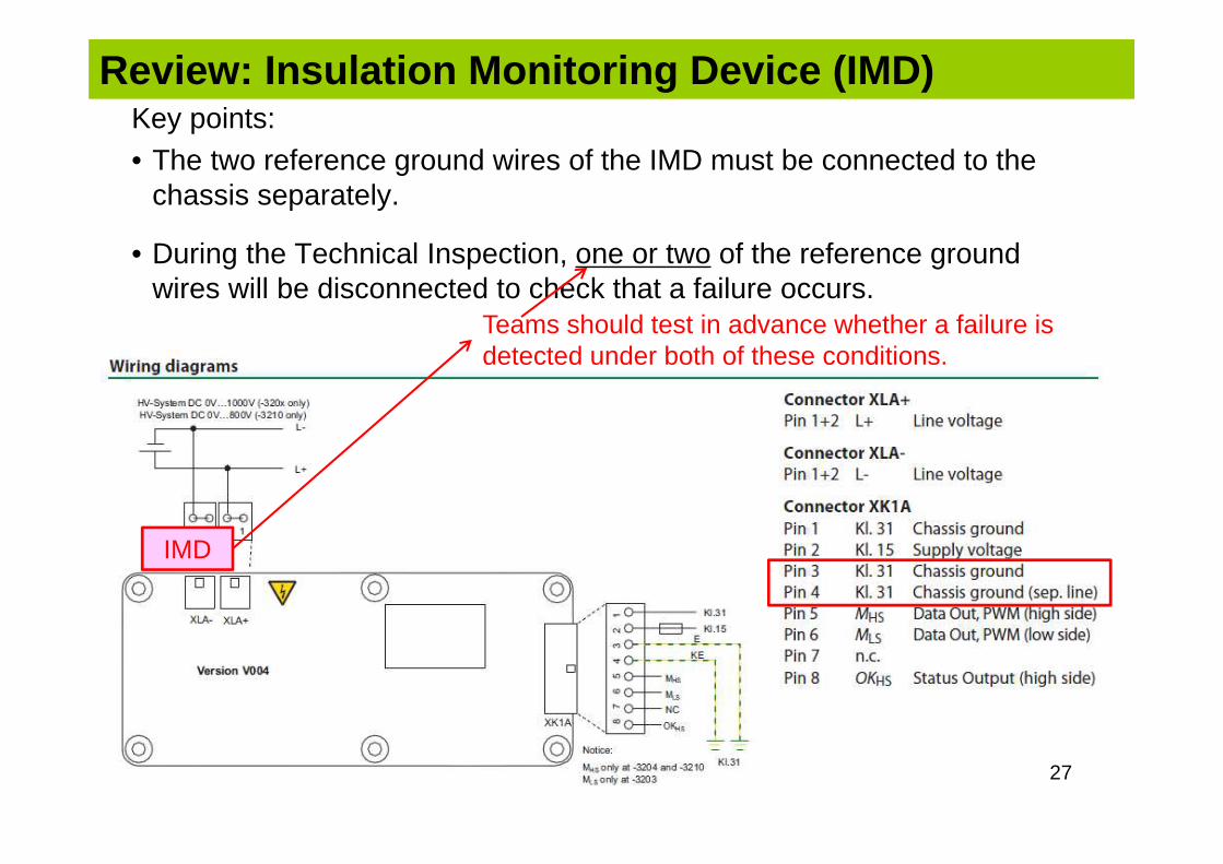
Key points: • The two reference ground wires of the IMD must be connected to the
chassis separately.
• During the Technical Inspection, one or two of the reference ground wires will be disconnected to check that a failure occurs.
Review: Insulation Monitoring Device (IMD)
Teams should test in advance whether a failure is detected under both of these conditions.
27
IMD

28
2. Key Points of Electrical Technical Inspection: Sheet 10
• Each team should prepare a stand that can hold the car with all four wheels approximately 50 to 150 mm above the ground.
• Seals will be attached to plastic covers and the like used as a countermeasure against rain. → These cannot be removed.
→ Use a structure that does not use tape or the like to seal against rain.• In the event of an emergency, teams should bring enough insulated gloves for
the people required to lift the car up.• This test can be failed in circumstances other than an insulation failure
(electrical leakage) (e.g., sensor signal disruption leading to shutdown).
EV3: Rain Test
• After accelerating, the system must be stopped by pressing the shutdown button before braking.
• Since it is more difficult to lock the tires with an EV than a gasoline-powered car, the same design may not work.
This is caused by higher weight and the rotational inertia of the motor applied to the drive wheels.
Reference: Brake Test

• Dangerous operations Jacking up the car Rotating the motor Measuring potential Charging Operations involving touching the accumulator
container must be carried out in the Charging Area.
High-voltage wiring connection Wiring inside the accumulator container
Operational Safety in the Technical Inspections
Although the following operations will not be carried out at the Technical Inspection Area, see the following slides for hints about how to carry them out.
The team members will be asked to perform various operations during the Technical Inspections. It is important that these tasks are carried out calmly.

© Photograph by Shidhartha De at Formula Student Germany (FSG)
Operational Safety in the Technical Inspections
Key point:Only the connection operation area is uncovered.
Key point:Short circuits caused by screws and the like can cause molten metal to jump out like fireworks.

© Photograph by Shidhartha De at Formula Student Germany (FSG)
Operational Safety in the Technical Inspections
Key point:Cables move.Although troublesome to set up, covers can be beneficial.


