Final Report Contract No.: M09PC00005 Evaluate New Materials for Deepwater Synthetic Mooring Systems Response to Solicitation Number M08PS00074, Issued by the Minerals Management Service U. S. Department of Interior, Posted date: May 19, 2008 White Paper Objective: Item 1: “Compare materials for use in construction of a synthetic mooring system (polyester, High modulus polyethylene-HMPE, Kevlar, etc)” Submitted: April 15, 2010 Applicant: Stress Engineering Services, Inc. PN 118189 #00005
Transcript
Final Report Contract No.: M09PC00005
Evaluate New Materials for Deepwater Synthetic Mooring Systems
Response to Solicitation Number M08PS00074,
Issued by the Minerals Management Service
U. S. Department of Interior,
Posted date: May 19, 2008
White Paper Objective:
Item 1:
“Compare materials for use in construction of a
synthetic mooring system (polyester, High modulus
polyethylene-HMPE, Kevlar, etc)”
Submitted: April 15, 2010
Applicant:
Stress Engineering Services, Inc.
PN 118189
#00005
Final Report
Evaluate New Materials for Deepwater Synthetic Mooring Systems
Response to Solicitation Number M08PS00074, Issued by the Minerals Management Service
U. S. Department of Interior, Posted date: May 19, 2008
White Paper Objective:
Item 1:
“Compare materials for use in construction of a
synthetic mooring system (polyester, High modulus polyethylene-HMPE, Kevlar, etc)”
Submitted: April 15, 2010
Contractor:
Stress Engineering Services, Inc
PN 118189
Prepared by:
Ray R. Ayers, PhD., P.E. David T. Renzi
Reviewed by:
Saltuk B. Aksu, PhD
Stress Engineering Services, Inc. 13800 Westfair East Drive
Houston TX 77041
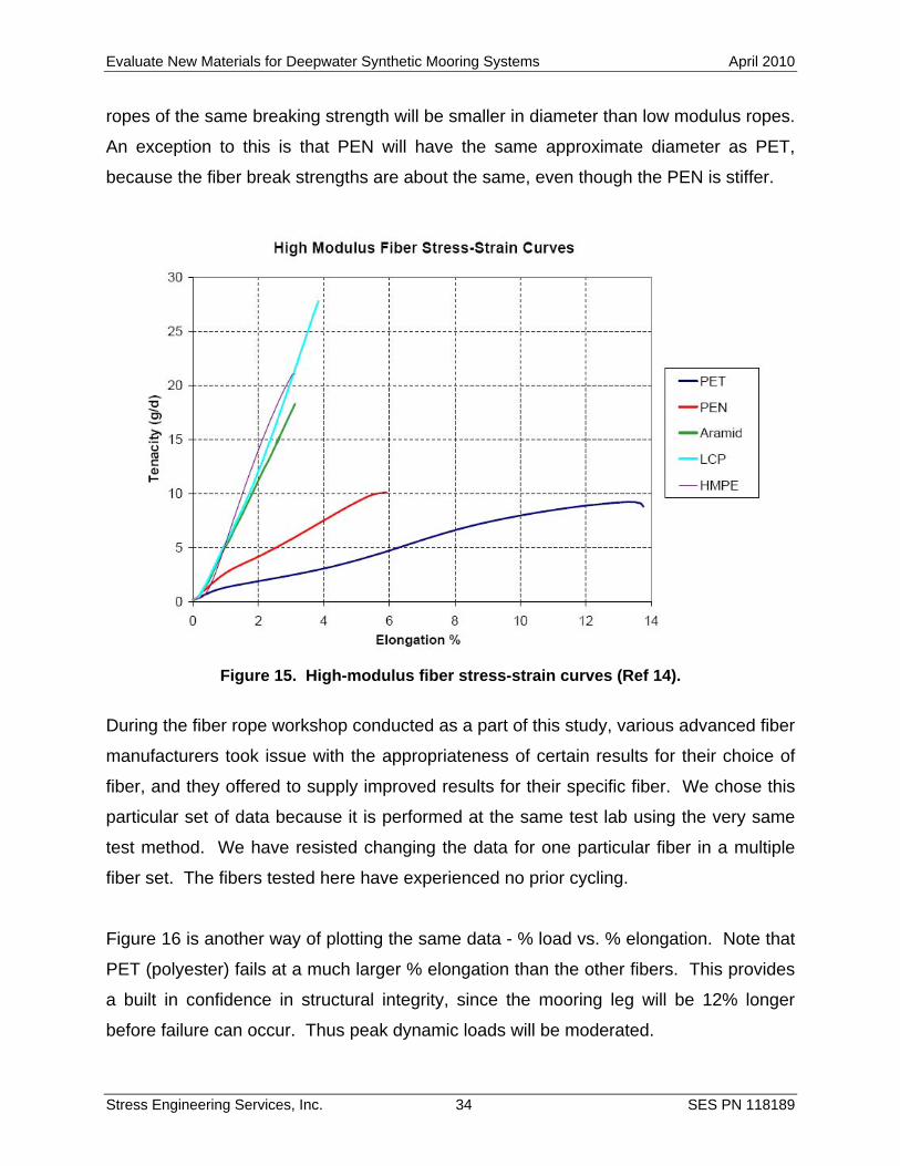
Evaluate New Materials for Deepwater Synthetic Mooring Systems April 2010
Stress Engineering Services, Inc. i SES PN 118189
LIMITATIONS OF THIS REPORT
The scope of this report is limited to the matters expressly covered. This report is
prepared for the sole benefit of the Minerals Management Service (MMS). In preparing
this report, Stress Engineering Services, Inc. (SES) has relied on information provided
by the MMS. Stress Engineering Services, Inc. (SES) has made no independent
investigation as to the accuracy or completeness of such information and has assumed
that such information was accurate and complete. Further, Stress Engineering Services,
Inc. (SES) is not able to direct or control the operation or maintenance of client’s
equipment or processes.
All recommendations, findings and conclusions stated in this report are based upon
facts and circumstances, as they existed at the time that this report was prepared. A
change in any fact or circumstance upon which this report is based may adversely affect
the recommendations, findings, and conclusions expressed in this report.
NO IMPLIED WARRANTY OF MERCHANTABILITY OR FITNESS FOR A
PARTICULAR PURPOSE SHALL APPLY. STRESS ENGINEERING SERVICES, INC.
MAKES NO REPRESENTATION OR WARRANTY THAT THE IMPLEMENTATION OR
USE OF THE RECOMMENDATIONS, FINDINGS, OR CONCLUSIONS OF THIS
REPORT WILL RESULT IN COMPLIANCE WITH APPLICABLE LAWS OR PERFECT
RESULTS.
Evaluate New Materials for Deepwater Synthetic Mooring Systems April 2010
Stress Engineering Services, Inc. ii SES PN 118189
TABLE OF CONTENTS
Limitations of This Report................................................................................................. i
Scope of Work................................................................................................................. 7
Part A: Conclusions........................................................................................................ 8
Part A: Recommendations ............................................................................................. 9
Part B: Conclusions...................................................................................................... 10
Part B: Recommendations ........................................................................................... 11
PARTS A and B REPORT............................................................................................. 12 Background ............................................................................................................... 12 Approach ................................................................................................................... 12 Experience with polyester in Brazil and GOM............................................................ 13 Breakthrough Technology for Deep Waters............................................................... 14 Advanced Fibers over Polyester?.............................................................................. 14
PART A: Parametric Study of Advanced Fiber Ropes VS. Polyester Fiber Ropes for Various Water Depths ................................................................................................... 15
Input Information........................................................................................................ 15 Analysis Results ........................................................................................................ 20 Mooring Line Tensions .............................................................................................. 22 Fatigue of Mooring Chain and Risers ........................................................................ 24 Relationship of Offset (% water depth) with Offset Force .......................................... 26
Overview ................................................................................................................ 40 Comparison of Stiffnesses (Modulii) for Advanced Fiber Ropes ............................ 42 A Comparison of Rope Diameters for Various Advanced Fibers............................ 45
Evaluate New Materials for Deepwater Synthetic Mooring Systems April 2010
Stress Engineering Services, Inc. iii SES PN 118189
Fatigue Testing to Determine Strand-on-Strand Wear ........................................... 46 Strand-on-Strand Abrasion Testing – The 20-Hurricane Test ................................ 46 Other Failure Modes for Advanced Fiber Ropes .................................................... 49 Regulatory Requirements for Mooring Systems Using Synthetic Fiber Ropes....... 50 API RP 2SM Relevance for Advanced Fiber Ropes............................................... 50 Advanced Fiber Workshop Expert Advice.............................................................. 51
–– Rigid BodiesRigid Bodies–– Risers and MooringsRisers and Moorings–– Connecting LinksConnecting Links
•• Example Example –– Large SemiLarge Semi–– 16 Mooring Lines16 Mooring Lines–– 20 Steel 20 Steel CatenaryCatenary RisersRisers
A-2
Coupled Analysis of Floating Production Systems
4/10/2009
Stress Engineering Services, Inc. 2
Coupled AnalysisCoupled Analysis
•• Details in a Single ModelDetails in a Single Model–– Floater(sFloater(s))–– RisersRisers–– MooringMooring
•• Why Coupled Analysis?Why Coupled Analysis?–– AccuracyAccuracy–– EfficiencyEfficiency–– Damping from Drag on Mooring and RisersDamping from Drag on Mooring and Risers
Numerical ModelsNumerical Models
•• FloaterFloater–– Modeled as a Rigid BodyModeled as a Rigid Body
•• Mooring Lines and RisersMooring Lines and Risers–– Slender Elastic LinesSlender Elastic Lines
•• Connecting LinksConnecting Links–– Springs, etc.Springs, etc.
A-3
Coupled Analysis of Floating Production Systems
4/10/2009
Stress Engineering Services, Inc. 3
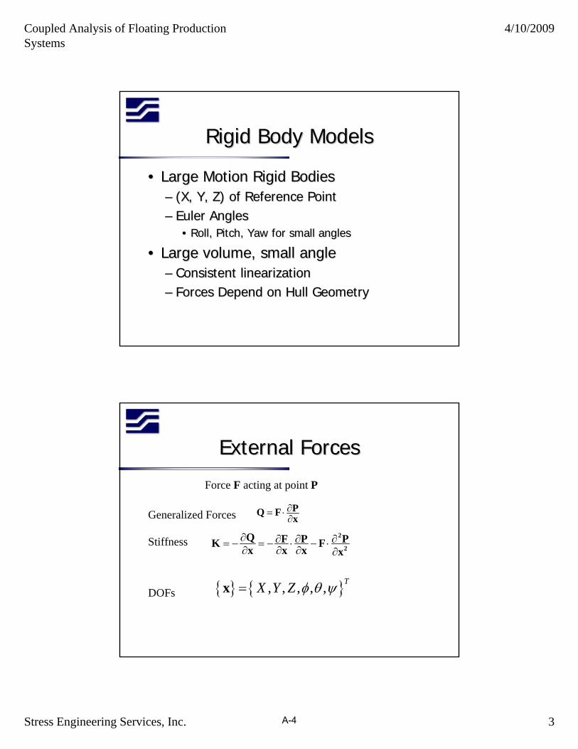
Rigid Body ModelsRigid Body Models
•• Large Motion Rigid BodiesLarge Motion Rigid Bodies–– (X, Y, Z) of Reference Point(X, Y, Z) of Reference Point–– Euler AnglesEuler Angles
•• Roll, Pitch, Yaw for small anglesRoll, Pitch, Yaw for small angles
•• Large volume, small angleLarge volume, small angle–– Consistent linearizationConsistent linearization–– Forces Depend on Hull GeometryForces Depend on Hull Geometry
External ForcesExternal Forces
∂= ⋅∂PQ F x
∂ ∂ ∂ ∂= − = − ⋅ − ⋅∂ ∂ ∂ ∂
2
2Q F P PK Fx x x x
{ } { }, , , , ,TX Y Z φ θ ψ=x
Force F acting at point P
Generalized Forces
Stiffness
DOFs
A-4
Coupled Analysis of Floating Production Systems
4/10/2009
Stress Engineering Services, Inc. 4
Slender Elastic LinesSlender Elastic Lines
( ) ( )B λ ρ′′ ′′ ′ ′− + + =r r q r&&
012 ( 1)
T TAE−′ ′⋅ − =r r
[ ] 0 0
0
( ) ( ) | |L
L LB dsδ λ δ ρ δ δ δ′′ ′′ ′ ′ ′ ′− ⋅ − ⋅ + − ⋅ = × ⋅ − ⋅∫ r r r r q r r r M r F r&&
∫ ∫−
=−′⋅′L L
dsAE
TTds
0 0
021 )1( δλδλrr
Equation of Motion
Constraint
Galerkin’s Method
Hydrodynamic LoadHydrodynamic Load
d n n m n a nC C C= + −q V V a r&&Morison Equation
Drag Force Linearized in Frequency Domain
Linearization Matches Energy Dissipated
A-5
Coupled Analysis of Floating Production Systems
4/10/2009
Stress Engineering Services, Inc. 5
Connecting LinksConnecting Links
( ) ( )11 2 1 22V K= − ⋅ −P P P P
1 2 1 212
1 2 1 2rV K⎛ ⎞ ⎛ ⎞
= − ⋅ −⎜ ⎟ ⎜ ⎟⎝ ⎠ ⎝ ⎠
E E E EE E E E
;V ∂∂= − = −∂ ∂
QQ Kx x
Extensional Spring
Rotational Spring
Generalized Force and Stiffness
Time Domain ProceduresTime Domain Procedures
zyQzMQyM
===
&
&
&& or
( )( ) ( )
( )
11 12 32 2
12
n nh
h
++ −
++
−⎛ ⎞ = − − + −⎜ ⎟⎝ ⎠−
= +
n 1 nn n n 1
n 1 nn n 1
z zM F K y y H H
y y z z
Reduce to 2 First Order Equations
Trapezoidal Rule Integration
A-6
Coupled Analysis of Floating Production Systems
4/10/2009
Stress Engineering Services, Inc. 6
Frequency Domain ProceduresFrequency Domain Procedures
•• Nonlinear Nonlinear StaticsStatics•• LinearizeLinearize at Mean Positionat Mean Position•• Statistical LinearizationStatistical Linearization
–– Coefficients Depend on SolutionCoefficients Depend on Solution–– IterativeIterative
Rational Approach To Marine SystemsRational Approach To Marine SystemsDesign Basis & MetOcean
Load Cases
GLOBAL ANALYSIS RisersModels
ForcesHull
Hydrodynamics
Mooring
MotionsStrength & Fatigue
RisersMooring
Meets Requirements?No No
Coefficients
Model
Models
Mod
ify
Mod
ify
DoneYes
Results
& MotionsResults & Motions
A-7
Coupled Analysis of Floating Production Systems
4/10/2009
Stress Engineering Services, Inc. 7
Example Example -- SemiSemi16 Mooring Lines and 20 16 Mooring Lines and 20 SCRsSCRs
Size of ModelSize of Model
•• Riser Elements 3,170Riser Elements 3,170•• Mooring Elements 384Mooring Elements 384•• Total Line Elements 3,554Total Line Elements 3,554•• Degrees of Freedom 21,546Degrees of Freedom 21,546
A-8
Coupled Analysis of Floating Production Systems
4/10/2009
Stress Engineering Services, Inc. 8
Time Domain vs. Frequency DomainTime Domain vs. Frequency Domain
•• Fatigue Sea State (HFatigue Sea State (Hss=3m)=3m)–– Time Domain Time Domain –– 10 one hour simulations10 one hour simulations–– Comparison of key resultsComparison of key results
•• MotionsMotions•• SCR and Mooring LineSCR and Mooring Line
•• Extreme Sea State (HExtreme Sea State (Hss=12.2m)=12.2m)–– Use FD Result to force component in TDUse FD Result to force component in TD
•• SCRSCR•• Mooring LineMooring Line
Fatigue Sea StateFatigue Sea State
•• Time StepsTime Steps–– Time Step 0.1sTime Step 0.1s–– TransientTransient 2000s2000s–– Single Replicate 3600sSingle Replicate 3600s–– 10 Replicates 10 Replicates 560,000560,000 time stepstime steps
•• Coupled Frequency Domain AnalysisCoupled Frequency Domain Analysis•• Motions from Frequency DomainMotions from Frequency Domain
–– 10 one hour simulations for SCR10 one hour simulations for SCR–– 100 one hour simulations for Mooring Line100 one hour simulations for Mooring Line
•• ComparisonsComparisons–– SCR Stress at SeafloorSCR Stress at Seafloor–– Mooring Line Tension StatisticsMooring Line Tension Statistics
SCR Stress at SeafloorSCR Stress at Seafloor
0
1,000
2,000
3,000
4,000
5,000
6,000
220 240 260 280 300 320
Distance along riser from bottom, m
Var
ianc
e of
Str
ess,
(M
Pa)
2
Individual Replicates
Frequency Domain
A-12
Coupled Analysis of Floating Production Systems
4/10/2009
Stress Engineering Services, Inc. 12
Mooring Line StatisticsMooring Line Statistics
0.0
0.2
0.4
0.6
0.8
1.0
1.2
1.4
0 20 40 60 80 100
Replicate
Tim
e D
omai
n/F
requ
ency
Dom
ain
Variance of TensionSecond Moment of Tension
ConclusionConclusion
•• Coupled Modeling DescribedCoupled Modeling Described–– Accurate and EfficientAccurate and Efficient–– Both Time Domain and Frequency DomainBoth Time Domain and Frequency Domain
•• Frequency DomainFrequency Domain–– Accuracy and Efficiency for Routine DesignAccuracy and Efficiency for Routine Design
•• Time DomainTime Domain–– For TransientsFor Transients–– Some Extreme Load CasesSome Extreme Load Cases
A-13
Evaluate New Materials for Deepwater Synthetic Mooring Systems April 2010
Stress Engineering Services, Inc. B-1 SES PN 118189
APPENDIX B
MMS MOORING ANALYSIS SUMMARY
1
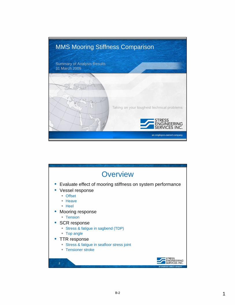
MMS Mooring Stiffness Comparison
Summary of Analysis Results31 March 2009
2
Overview• Evaluate effect of mooring stiffness on system performance• Vessel response
OffsetHeaveHeel
• Mooring responseTension
• SCR responseStress & fatigue in sagbend (TDP)Top angle
• TTR responseStress & fatigue in seafloor stress jointTensioner stroke
B-2
2
3
Overview, cont.• 3 Water Depths
5,000 ft
10,000 ft
15,000 ft
• 3 Mooring Rope Stiffnesses17.2 x MBL
34.4 x MBL
51.6 x MBL
• 4 EnvironmentsFatigue Event (HS = 6.6 ft)
10-Yr Hurricane (HS = 32.8 ft)
100-Yr Hurricane (HS = 51.8 ft)
1000-Yr Hurricane (HS = 65.0 ft)
4
Mooring Model• Nominal horizontal force = 295-kips
• Dual casing riserOuter casing - 10.750-in x 0.650-in
Inner casing – 7.625-in x 0.500-in
Tubing – 3.500-in x 0.254-in
• Steel stress jointLength = 29.2-ft
Wall thickness at base of taper = 1.500-in
10
TTR Model, cont.
WaterDepth
NominalTension
TensionerStiffness Overpull
(ft) (kips) (kips) (kips)5,000 767 11.5 200
10,000 1,289 19.3 20015,000 1,811 27.2 200
• Overpull at stress joint = 200-kips
• Tensioner stiffness = 1.5% of nominal tension
B-6
6
11
Load Case Matrix
FATIGUE
Small Seastate(3 Heading)
H10(3 Headings)
H100(3 Headings)
H1000(3 Headings)
Low X X X XMedium X X X X
High X X X XLow X X X X
Medium X X X XHigh X X X XLow X X X X
Medium X X X XHigh X X X X
5,000 feet
10,000 feet
15,000 feetFH =
295 kips
10.75-inch ODInsulatedFlowline
(T/WD=2,900)
Configuration
Configuration 1(C1)
SCRConfigurationWater Depth Mooring
Configuration
Configuration 2(C2)
Configuration 3(C3)
TTRConfiguration
10.75-inch ODDual Casing
(Overpull = 200-kips)
10.75-inch ODDual Casing
(Overpull = 200-kips)
FH =
295 kips
FH =
295 kips
10.75-inch ODInsulatedFlowline
(T/WD=2,900)
10.75-inch ODInsulatedFlowline
(T/WD=2,900)
SyntheticRope
Stiffness
STRENGTH
10.75-inch ODDual Casing
(Overpull = 200-kips)
12
Vessel Offset – Fatigue Event
-5
0
5
10
15
20
25
30
35
Low Medium High Low Medium High Low Medium High
Off
set (
ft)
MMS Mooring Analysis Study12 Mooring Line Configuration
Vessel Offset in Fatigue Seastate (HS = 6.56 ft)
5,000 ft Water Depth 10,000 ft Water Depth 15,000 ft Water Depth
B-7
7
13
Vessel Offset – Fatigue Event
-0.10%
-0.05%
0.00%
0.05%
0.10%
0.15%
0.20%
0.25%
0.30%
Low Medium High Low Medium High Low Medium High
Off
set (
% W
D)
MMS Mooring Analysis Study12 Mooring Line Configuration
Vessel Offset in Fatigue Seastate (HS = 6.56 ft)
5,000 ft Water Depth 10,000 ft Water Depth 15,000 ft Water Depth
14
Vessel Offset – 100-Yr Hurricane
0
50
100
150
200
250
300
350
400
450
500
Low Medium High Low Medium High Low Medium High
Off
set (
ft)
MMS Mooring Analysis Study12 Mooring Line Configuration
Vessel Offset in 100-Year Hurricane (HS = 51.8 ft)
5,000 ft Water Depth 10,000 ft Water Depth 15,000 ft Water Depth
B-8
8
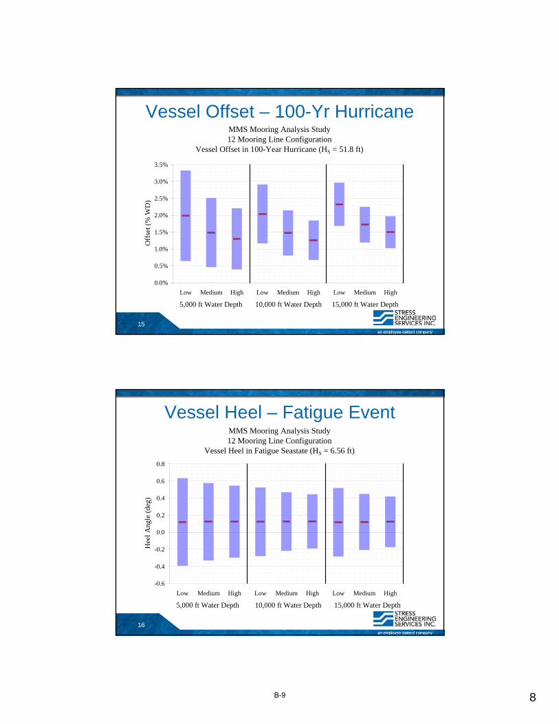
15
Vessel Offset – 100-Yr Hurricane
0.0%
0.5%
1.0%
1.5%
2.0%
2.5%
3.0%
3.5%
Low Medium High Low Medium High Low Medium High
Off
set (
% W
D)
MMS Mooring Analysis Study12 Mooring Line Configuration
Vessel Offset in 100-Year Hurricane (HS = 51.8 ft)
5,000 ft Water Depth 10,000 ft Water Depth 15,000 ft Water Depth
16
Vessel Heel – Fatigue Event
-0.6
-0.4
-0.2
0.0
0.2
0.4
0.6
0.8
Low Medium High Low Medium High Low Medium High
Hee
l Ang
le (
deg)
MMS Mooring Analysis Study12 Mooring Line Configuration
Vessel Heel in Fatigue Seastate (HS = 6.56 ft)
5,000 ft Water Depth 10,000 ft Water Depth 15,000 ft Water Depth
B-9
9
17
Vessel Heel – 100-Yr Hurricane
-6
-4
-2
0
2
4
6
8
10
12
Low Medium High Low Medium High Low Medium High
Hee
l Ang
le (
deg)
MMS Mooring Analysis Study12 Mooring Line Configuration
Vessel Heel in 100-Year Hurricane (HS = 51.8 ft)
5,000 ft Water Depth 10,000 ft Water Depth 15,000 ft Water Depth
18
Vessel Heave – Fatigue Event
-0.15
-0.10
-0.05
0.00
0.05
0.10
0.15
Low Medium High Low Medium High Low Medium High
Hea
ve (
ft)
MMS Mooring Analysis Study12 Mooring Line Configuration
Vessel Heave in Fatigue Seastate (HS = 6.56 ft)
5,000 ft Water Depth 10,000 ft Water Depth 15,000 ft Water Depth
B-10
10
19
Vessel Heave – 100-Yr Hurricane
-40
-30
-20
-10
0
10
20
30
40
Low Medium High Low Medium High Low Medium High
Hea
ve (
ft)
MMS Mooring Analysis Study12 Mooring Line Configuration
Vessel Heave in 100-Year Hurricane (HS = 51.8 ft)
5,000 ft Water Depth 10,000 ft Water Depth 15,000 ft Water Depth
20
Mooring Tension – 100-Yr Hurricane
0
500
1,000
1,500
2,000
2,500
3,000
3,500
4,000
Low Medium High Low Medium High Low Medium High
Ten
sion
(ki
ps)
MMS Mooring Analysis Study12 Mooring Line Configuration
Tension in 100-Yr Hurricane (HS = 51.8 ft)
5,000 ft Water Depth 10,000 ft Water Depth 15,000 ft Water Depth
100% MBL = 3,428-kips
80% MBL = 2,742-kips
60% MBL = 2,057-kips
B-11
11
21
Mooring Tension – 100-Yr Hurricane
0%
20%
40%
60%
80%
100%
120%
Low Medium High Low Medium High Low Medium High
Ten
sion
(%
MB
L)
MMS Mooring Analysis Study12 Mooring Line Configuration
Tension in 100-Yr Hurricane (HS = 51.8 ft)
5,000 ft Water Depth 10,000 ft Water Depth 15,000 ft Water Depth
100% MBL = 3,428-kips
80% MBL = 2,742-kips
60% MBL = 2,057-kips
22
SCR – Relative TDP Stress
0.0
0.2
0.4
0.6
0.8
1.0
1.2
1.4
1.6
1.8
Low Medium High Low Medium High Low Medium High
Fatigue Event 10-Yr Hurricane
100-Yr Hurricane 1000-Yr Hurricane
MMS Mooring Analysis Study - 12 Mooring Line ConfigurationComparison of Relative Stress at SCR TouchdownBaseline = 10,000 ft Water Depth, Low Stiffness
Rel
ativ
e St
ress
5,000 ft Water Depth 10,000 ft Water Depth 15,000 ft Water Depth
B-12
12
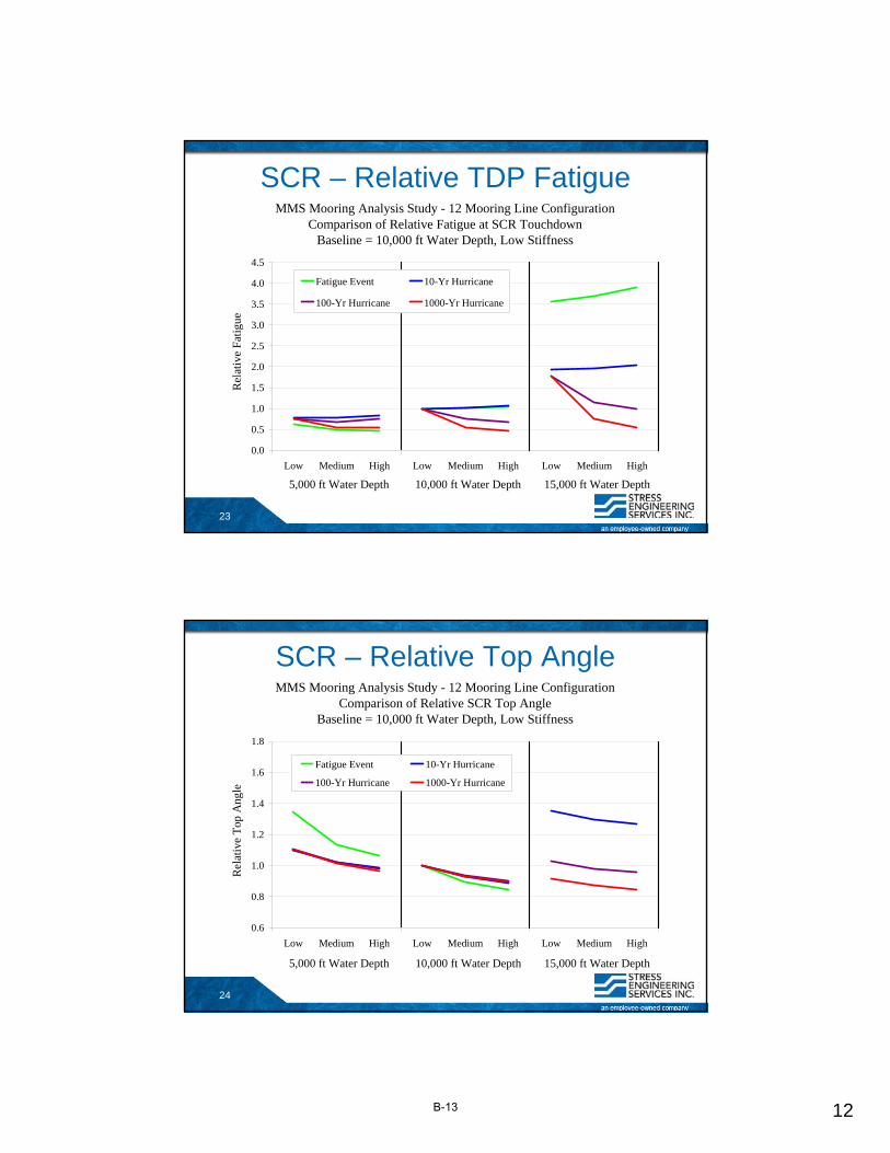
23
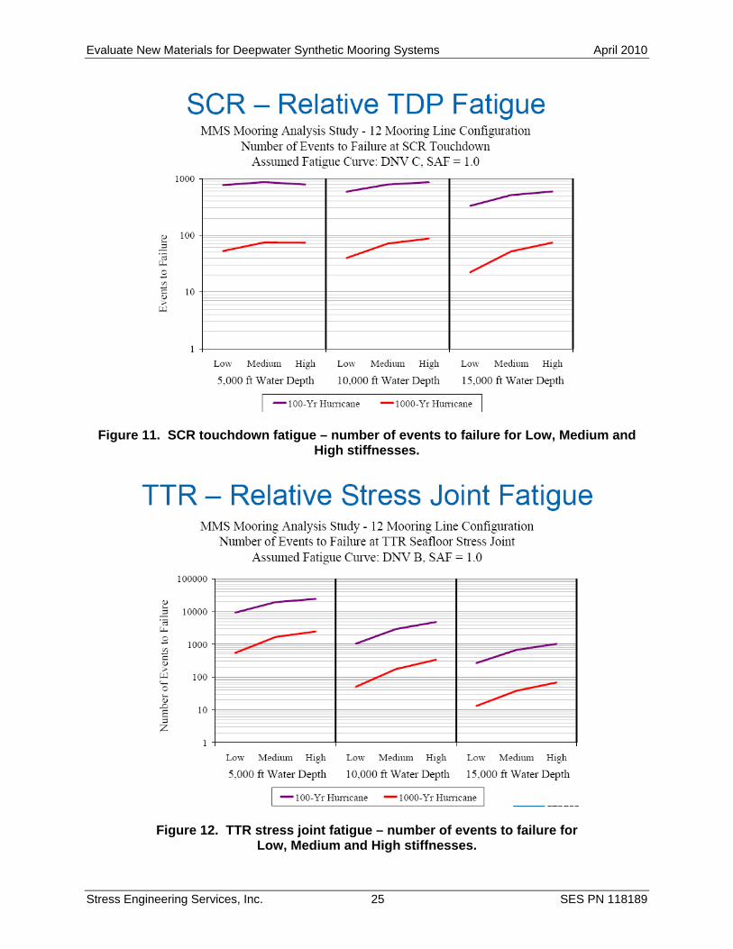
SCR – Relative TDP Fatigue
0.0
0.5
1.0
1.5
2.0
2.5
3.0
3.5
4.0
4.5
Low Medium High Low Medium High Low Medium High
Fatigue Event 10-Yr Hurricane
100-Yr Hurricane 1000-Yr Hurricane
MMS Mooring Analysis Study - 12 Mooring Line ConfigurationComparison of Relative Fatigue at SCR Touchdown
Baseline = 10,000 ft Water Depth, Low StiffnessR
elat
ive
Fat
igue
5,000 ft Water Depth 10,000 ft Water Depth 15,000 ft Water Depth
24
SCR – Relative Top Angle
0.6
0.8
1.0
1.2
1.4
1.6
1.8
Low Medium High Low Medium High Low Medium High
Fatigue Event 10-Yr Hurricane
100-Yr Hurricane 1000-Yr Hurricane
MMS Mooring Analysis Study - 12 Mooring Line ConfigurationComparison of Relative SCR Top Angle
Baseline = 10,000 ft Water Depth, Low Stiffness
Rel
ativ
e T
op A
ngle
5,000 ft Water Depth 10,000 ft Water Depth 15,000 ft Water Depth
B-13
13
25
TTR – Relative Stress Joint Stress
0.0
0.2
0.4
0.6
0.8
1.0
1.2
1.4
1.6
Low Medium High Low Medium High Low Medium High
Fatigue Event 10-Yr Hurricane
100-Yr Hurricane 1000-Yr Hurricane
MMS Mooring Analysis Study - 12 Mooring Line ConfigurationComparison of Relative Stress at Seafloor Stress Joint
Baseline = 10,000 ft Water Depth, Low StiffnessR
elat
ive
Stre
ss
5,000 ft Water Depth 10,000 ft Water Depth 15,000 ft Water Depth
26
TTR – Relative Stress Joint Fatigue
0.0
0.5
1.0
1.5
2.0
2.5
3.0
3.5
4.0
4.5
Low Medium High Low Medium High Low Medium High
Fatigue Event 10-Yr Hurricane
100-Yr Hurricane 1000-Yr Hurricane
MMS Mooring Analysis Study - 12 Mooring Line ConfigurationComparison of Relative Fatigue at Seafloor Stress Joint
Baseline = 10,000 ft Water Depth, Low Stiffness
Rel
ativ
e Fa
tigu
e
5,000 ft Water Depth 10,000 ft Water Depth 15,000 ft Water Depth
B-14
14
27
TTR – Relative Tensioner Stroke
0.6
0.8
1.0
1.2
1.4
1.6
1.8
Low Medium High Low Medium High Low Medium High
Fatigue Event 10-Yr Hurricane
100-Yr Hurricane 1000-Yr Hurricane
MMS Mooring Analysis Study - 12 Mooring Line ConfigurationComparison of Relative Tensioner Stroke
Baseline = 10,000 ft Water Depth, Low StiffnessR
elat
ive
Ten
sion
er S
trok
e
5,000 ft Water Depth 10,000 ft Water Depth 15,000 ft Water Depth
28
Work Progress
• Budgeted hours – 80 hrs
• DFR ~ 38 hrs as of 12:00 PM, 31 March 2009
B-15
Evaluate New Materials for Deepwater Synthetic Mooring Systems April 2010
Stress Engineering Services, Inc. C-1 SES PN 118189
APPENDIX C
POLYESTER ROPE FATIGUE RESULTS
POLYESTER ROPE FATIGUE RESULTS Plot of polyester fatigue data based on the TTI/NEL Durability Study (OTC 17510) provided by David Smith of ExxonMobil for the API RP 2SM re-write task group.
C-2
Evaluate New Materials for Deepwater Synthetic Mooring Systems April 2010
Stress Engineering Services, Inc. D-1 SES PN 118189
APPENDIX D
WORKSHOP RESULTS
REPORT ON MMS-SPONSORED WORKSHOP ON:
USE OF ADVANCED FIBERS FOR DEEPWATER MOORING SYSTEMS
Held September 28, 2009
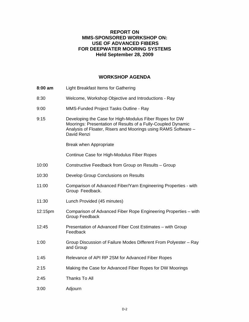
WORKSHOP AGENDA 8:00 am Light Breakfast Items for Gathering 8:30 Welcome, Workshop Objective and Introductions - Ray 9:00 MMS-Funded Project Tasks Outline - Ray 9:15 Developing the Case for High-Modulus Fiber Ropes for DW Moorings: Presentation of Results of a Fully-Coupled Dynamic Analysis of Floater, Risers and Moorings using RAMS Software – David Renzi Break when Appropriate Continue Case for High-Modulus Fiber Ropes 10:00 Constructive Feedback from Group on Results – Group 10:30 Develop Group Conclusions on Results 11:00 Comparison of Advanced Fiber/Yarn Engineering Properties - with Group Feedback. 11:30 Lunch Provided (45 minutes) 12:15pm Comparison of Advanced Fiber Rope Engineering Properties – with Group Feedback 12:45 Presentation of Advanced Fiber Cost Estimates – with Group Feedback 1:00 Group Discussion of Failure Modes Different From Polyester – Ray and Group 1:45 Relevance of API RP 2SM for Advanced Fiber Ropes 2:15 Making the Case for Advanced Fiber Ropes for DW Moorings 2:45 Thanks To All 3:00 Adjourn
D-2
WORKSHOP PARTICIPANTS
WORKSHOP PRESENTATIONS
Presentations made in the workshop consisted of the PowerPoint slides found in Appendix B, as well as slides generally consisting of the figures used in Part B of the Final Report.
WORKSHOP FEEDBACK NOTES
Project Team Response is Provided in Italics
PART A: ANALYSIS PRESENTATION FEEDBACK Advanced fiber definition: Which stiffness of the rope is selected and why? Explained in Final Report
D-3
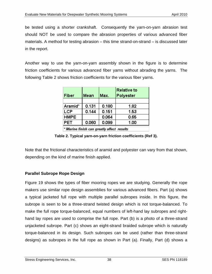
Are Loop current events included in the dynamic analysis? Yes – on offset plot. Need to show the response in time domain to verify the results – We save this for detailed design – this is FEED (Front End Engineering Design) Also need to show the offsets. Done On slide 28 add (y axis) Relative fatigue LIFE – Yes, you are correct. Agreed on the conclusion that polyester works for all water depths however the volume will be large. Yes, covered in Final Report Need to specify the conclusions more in detail ie. Cases that are studied… Explained in Final Report 3x change in the stiffness causes a change of 80% in lateral spring constant - Sometimes considered to have significant affect. Yes PART B: MATERIALS PRESENTATION FEEDBACK Fiber ropes are different from single fibers; single fiber results are purely academic. We do not agree – fibers are the building blocks of ropes. The charts shown from Bunsell – no consistent mean load… So, recommendation: Re-run the tests with appropriate mean loads. We agree, but have no funding to do so. Slide #2 HMPE 35-40 g/den. On Slide to we have a set of different fiber data performed under the same test method and equipment. To change one result would not be appropriate. If you have a better complete set of fiber data, we will consider using it instead. Single fiber failure in fatigue does not affect the performance of the rope as much. Yes, fiber results are only indicators. The truth is in less expensive 20-hurricane testing or more expensive full fatigue testing. Strand on strand? Or tension-tension fatigue testing? Explained in Final Report Have you studied HMPE in DeepStar 6403? This March 2004 DeepStar Report is proprietary to DeepStar. The report covers polyester, aramid and HMPE materials in some detail. The sensitivity study study of the spar hull mooring system does not appear to cover the semi-taut behavior of the mooring legs (no apparent catenary effect due to chain and connectors).
D-4
Compare fibers with respect to abrasion wear. The Final Report shows that strand-on-strand abrasion testing across different advanced fibers is not valid. A better test is strand-on-strand, 20 hurricane abrasion (cyclic wear) testing Permanent lines need more in-depth look. Agreed – See Final Report MMS Comments: Polyester is being used comfortably based on specific cases (water depth, platform type, etc.) One question: What kind of info do I need to compare polyester vs other fibers? See Final Report New product discussion:
Need to cover the design life. Yes, we consider 20 years. Demonstrate Applicability See Final Report Justification of the new product is needed (ie use in somewhere else with
success) All of the advanced fibers have applicability for rope applications outside of deepwater permanent mooring systems. But other applications are outside of our scope.
Try to find the best way to prove the product is safe to use. See our Final Report.
Peter Davies – ask for tension-tension fatigue data. Yes, but this is not an issue for advanced fiber ropes in general. More critical is steel mooring component fatigue. Fiber failure modes are known, focus on the rope data to understand how the rope will perform. Thank you for your advice. We believe that it is important to know both how fibers perform, and how that translates into rope performance. Aramid fiber stress-strain data will be provided (could not catch the name). To change one result would not be appropriate. If you have a better complete set of fiber data, we will consider using it instead. YOY Testing Discussion: Applicability of YOY on High modulus fibers is questioned. Yes, we believe that yarn-on yarn testing across different advanced fibers is not valid. We recommend strand on strand testing instead. It is hard to quantify the material due to dependence on the finish. Yes, different marine finishes for polyester and aramids impact rope performance, and we have indicated this in the Final Report.
D-5
Change in the yarn-on-yarn crankshaft stroke – Will it change anything? (Duration of life, etc?). We won’t know this unless we test it. What is the data source? (Should the fiber have marine finish? How long the marine finishes stay on the fiber?). Marine finishes are a proprietary part of the fiber or rope manufacturers confidential design. We can only test what we get, and explain that results might differ with different marine finishes. This discussion is appropriate for polyesters and aramids primarily. Agreed to conclusion using YOY results to compare 2 different fibers is not relevant. Thanks MMS:
Need a quick reference for mooring design. Need to be updated on the new technology and need to stay up with the
industry. Need to know the specific limitations of materials. Discussion on YOY and an alternative
To the best of our ability we have tried to provide a useful and concise guide to currently available fiber rope technology. Aside from this report, the new revised API RP 2SM, and the 2004 Handbook of Fibre Rope Technology are the best sources of advanced fiber rope technology. Strand On Strand Need to clarify: 3 Ropes for each data point. This is clarified in the Final Report. Temperature, Sample Length, Couple of photos of the sample, Failure point etc… This will be covered in the upcoming DeepStar CTR 9402 Report Are there any scaling effects? Scaling of subropes to full ropes is well understood. Scaling from fibers, to yarns, to strands to subropes is more complex. Rope makers keep their scaling techniques from yarn to subrope confidential, but the rope purchaser will have access to test results of the purchased rope. Mean load reduces the relative motion. We have lost the context of this question. Need a standard test procedure. See Final Report.
D-6
COST: Need to contact rope manufacturers for more accurate data. $/EA Need to use static stiffness value. We could not get consensus on cost at the workshop. The vendor community is very competitive. Advanced fiber materials will cost say two to four times that for commodity polyester fibers. The Final Report says no more. The advanced fiber rope purchaser will need to ask rope makers for the total cost (fiber cost plus rope manufacturing cost) of the desired rope.