Evaluating the Effect of Formal Techniques in Industry Ammar Osaiweran 1 , Jan Friso Groote 1 , Mathijs Schuts 2 , Jozef Hooman 3 , and Bart van Rijnsoever 2 1 Eindhoven University of Technology, Eindhoven, The Netherlands 2 Philips Healthcare, BU Interventional X-ray, Best, The Netherlands 3 Radboud University Nijmegen, Nijmegen, and Embedded Systems Institute, Eindhoven, The Netherlands {a.a.h.osaiweran,j.f.groote}@tue.nl,{mathijs.schuts,bart.van.Rijnsoever}@ philips.com,[email protected]Abstract. In this paper we evaluate the effectiveness of applying a for- mal component-based approach called Analytical Software Design (ASD) to the development of control software of an industrial project at Philips Healthcare. We analyze the performance of the ASD related tasks carried out during the development processes and report about the main issues encountered. Furthermore, we investigate whether introducing these for- mal techniques to industry could actually improve the quality and the productivity of the developed code compared to software developed by more traditional development methods. 1 Introduction Philips Healthcare develops a number of highly sophisticated medical systems, used for various clinical applications. One of these systems is the interventional X-ray (iXR) system, which depicted in Figure 1. Movable parts X-ray collimator X-ray pedal GUI joysticks & buttons Fig. 1. An interventional X-ray system The software practitioners at Philips Healthcare developing this type of sys- tems are constantly seeking approaches, tools and techniques to advance current
Transcript
Evaluating the Effect of Formal Techniques inIndustry
Ammar Osaiweran1, Jan Friso Groote1, Mathijs Schuts2, Jozef Hooman3, andBart van Rijnsoever2
1 Eindhoven University of Technology, Eindhoven, The Netherlands2 Philips Healthcare, BU Interventional X-ray, Best, The Netherlands
3 Radboud University Nijmegen, Nijmegen, and Embedded Systems Institute,Eindhoven, The Netherlands
Abstract. In this paper we evaluate the effectiveness of applying a for-mal component-based approach called Analytical Software Design (ASD)to the development of control software of an industrial project at PhilipsHealthcare. We analyze the performance of the ASD related tasks carriedout during the development processes and report about the main issuesencountered. Furthermore, we investigate whether introducing these for-mal techniques to industry could actually improve the quality and theproductivity of the developed code compared to software developed bymore traditional development methods.
1 Introduction
Philips Healthcare develops a number of highly sophisticated medical systems,used for various clinical applications. One of these systems is the interventionalX-ray (iXR) system, which depicted in Figure 1.
Movable
parts
X-ray
collimatorX-ray
pedal
GUI
joysticks
& buttons
Fig. 1. An interventional X-ray system
The software practitioners at Philips Healthcare developing this type of sys-tems are constantly seeking approaches, tools and techniques to advance current
2
software development processes. The purpose is to improve the quality of devel-oped code, enhance productivity, lower development costs, shorten the time tomarket, and increase end-user satisfaction.
As one of these new technologies, Philips Healthcare introduced to its devel-opment context a model-driven, formal component-based development approachcalled the Analytical Software Design (ASD). The approach was exploited fordefining formal interfaces and building mathematically verified software com-ponents. The ASD approach supports formal techniques by a commercial toolcalled the ASD:Suite, developed by the company Verum [29].
The focus of this paper is to investigate whether the use of these formaltechniques actually resulted in visible improvements to the developed software,demonstrating key issues encountered when incorporating the techniques withthe industrial development processes. The target of our investigation are thesoftware components of a subsystem of the X-ray machine, called the Frontendsubsystem.
The ASD technology was successful in other projects at Philips [23, 21, 24].In this paper we investigate whether the approach is also successful in otherprojects with other environments, circumstances and backgrounds. Moreover,we provide a more detailed quantitative analysis regarding the effectiveness ofthese techniques in industrial practices.
In order to determine any major improvement to the software developedby these formal techniques, we first need to collect quantifiable evidences andanalyze these techniques empirically and rigorously. Additionally, this requiresanswering the following research questions:
– Can these formal techniques deliver product code? And if so, is the code ofhigh or low quality?
– Do these formal techniques require more time in development compared totraditional development?
– What about the productivity using these techniques?– Do the techniques require specialized mathematicians for a successful appli-
cation?– Do these techniques always produce zero-defect software? If not, which types
of errors are expected and how many compared to industrial standards?– Which artifacts should we consider when evaluating these techniques empir-
ically? Should we include the formal models or the related code?
The paper is structured as follows. Section 2 briefly sketches the industrialcontext. In Section 3 the ASD approach is introduced to the limit needed inthis paper. Section 4 details the phases of developing the ASD components andthe main issues and limitations encountered. We analyze the data related tothe developed code to evaluate the ASD approach in Section 5. In Section 6we extend our analysis to study the cause and the type of errors that couldescape the formal techniques. Section 7 details the end results comparing theASD code with other code developed at Philips and also with the industrystandards reported worldwide. Section 8 details a number of industrial projectsthat we found incorporated formal techniques in their software development.
3
Finally, Section 9 contains our conclusions by answering the research questionsmentioned earlier.
2 Description of the project
The software that controls the X-ray machine is divided into a number of subsys-tems, including the Frontend (FE) subsystem. The FE is responsible for creatingX-ray images by controlling and managing physical hardware, such as the X-raygenerator, the X-ray detector, the table where patients can lay and the standthat holds the generator and the detector, as shown in Figure 1.
Previously, the FE subsystem was developed as a decentralized architecturein the sense that all units work on their own, observing changes of other unitsvia a shared blackboard and react accordingly. The main shortcoming of thistype of architecture was the difficulty of knowing the overall system state. Moreimportantly, incorporating innovations or new products of third-party supplierswas very challenging.
Therefore, some of the units of the FE subsystem were redesigned in order tomigrate to a new centralized, hierarchical component-based architecture, whileothers were kept intact and were reused in the new architecture (e.g., the unitsthat control the hardware devices).
The FE subsystem includes 22 units, two of which are the target of this study:the Application State Controller (ASC) and the Frontend Adapter (FEA). Bothunits comprise a number of modules that includes concurrent components withwell-defined interfaces and responsibilities.
One of the key responsibilities of the ASC is managing the external X-rayrequests, sent by the clinical operators via dedicated X-ray pedals and hand-switches. The unit counts, filters, and ensures priorities of such requests. It isalso responsible for maintaining the overall system state and coordinating inter-actions with units surrounding the FE subsystem.
The FEA unit is mainly responsible for the interfaces with other externalsubsystems, through a network. It exchanges information related to patientsand their exam details with other external parties. The unit is also responsiblefor monitoring the presence of other remote subsystems and converting incominginformation to readable xml and string formats.
The interaction of these units with other external parties is rather complexand error prone. Any party can issue requests or can enter a faulty state. Forexample, clinical users can press the pedals or the switches at any time, even ifthe internal components or the hardware are not prepared or configured yet forimage acquisition.
Moreover, the FE may lose the connection with the external subsystemsdue to network outage or errors in the subsystems at any time. Therefore, theASC and FEA units must always be robust against such situations and shouldprovide safe and convenient behavior to the end-users. In order to guaranteecorrectness of the developed components, the software practitioners decided toemploy the ASD technology aiming at detecting and preventing any potential
4
errors at early stages of the project and obtaining high quality software at theend of the project.
3 Use of formal methods
The ASD approach supports the development of formally verified software com-ponents by exploiting two types of models, both described as state machinesand specified using a similar tabular notation: the interface model and the de-sign model. We briefly describe these two types of models:
– The interface model is used as a formal means to describe not only themethods to be invoked on a component but also the external behavior. Theinterface model specifies the interaction protocol and the allowed or inhibitedsequences of invoking these methods by clients. Any interactions with usedcomponents are not included in the model.
– The design model of a component refines and extends the interface model bymore internal details. Usually, the design model uses the interface models ofother ASD and non ASD components. These interfaces, in turn, are indepen-dently refined by other design models (perhaps by other teams), facilitatingmulti-site, parallel development of components.
In order to allow the ASD approach to scale to industrial applications, theapproach is compositional [14] in the sense that components are verified in iso-lation. This means that the formal verification of a design model uses only theinterfaces of the surrounding used components, without considering their inter-nal implementation.
To ensure complete and consistent specifications, the models are describedusing the sequence-based specification technique [22]. Any ASD interface or de-sign model includes a complete specification in the sense that responses to everypossible input stimulus in every state must be described.
By translating the ASD tabular specifications to corresponding CSP models[28], which are checked by FDR2 [28, 9], the tool ASD:Suite can be used toformally verify that the external behavior captured by the interface model isformally refined by the corresponding design model. Moreover, the tool is usedto verify a predefined set of properties such as absence of deadlock and livelockunder all circumstances of use. ASD:Suite veils the CSP and the FDR2 detailsfrom end-users in order to enable practical industrial usage.
The ASD specification is restricted to develop components with data-independentcontrol decisions. This means that the correctness of parameter values of methodsis not checked by the tool, and components responsible for data manipulationsor algorithms should be implemented by other techniques. The technology isalso restricted to developing and verifying components with discrete behaviorand does not support the verification of timed systems.
The ASD component may include a queue to store incoming callback eventssent by used components, supporting an asynchronous communication mecha-nism. The queue runs in parallel (i.e., in a separate thread) with the designmodel and may cause interleaving with other components.
5
Code
generation Model
checking
State
Rule case
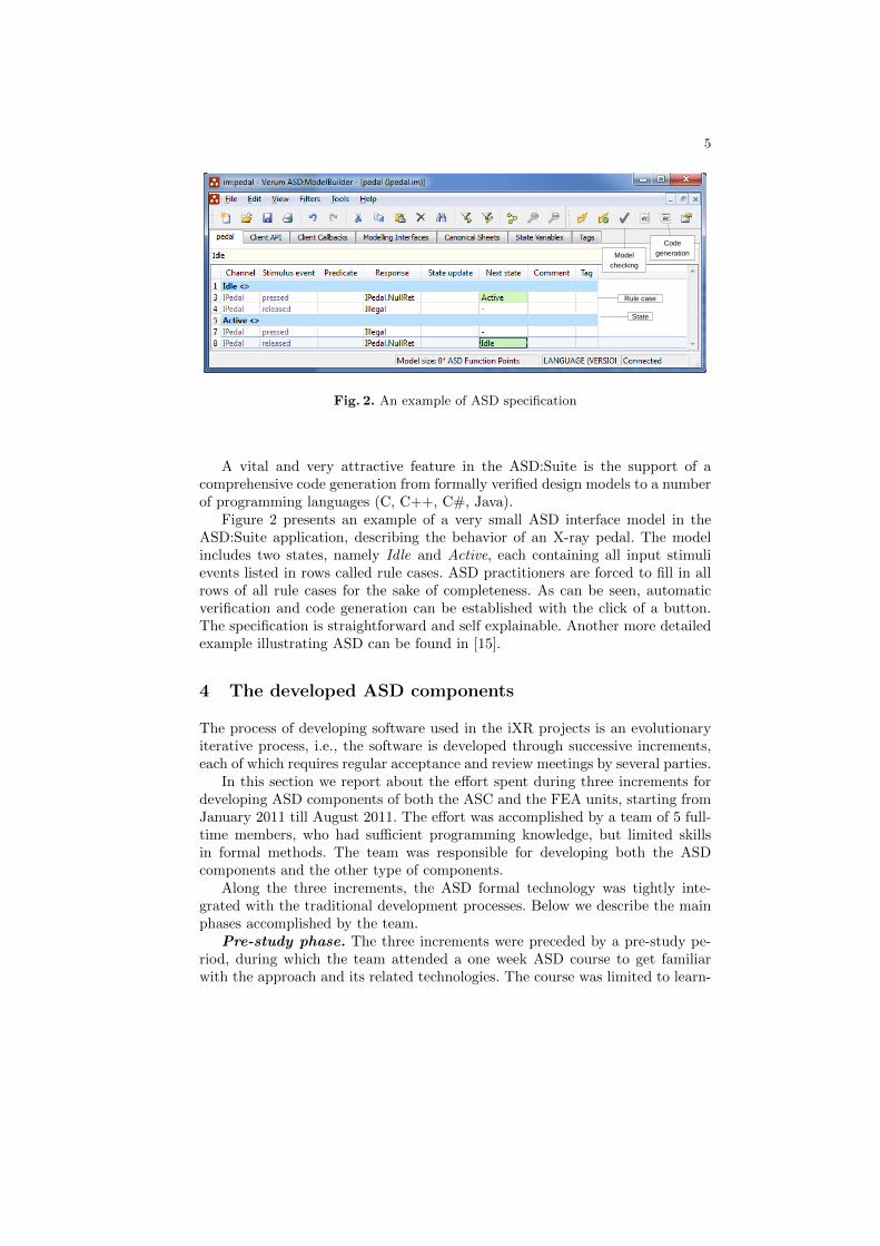
Fig. 2. An example of ASD specification
A vital and very attractive feature in the ASD:Suite is the support of acomprehensive code generation from formally verified design models to a numberof programming languages (C, C++, C#, Java).
Figure 2 presents an example of a very small ASD interface model in theASD:Suite application, describing the behavior of an X-ray pedal. The modelincludes two states, namely Idle and Active, each containing all input stimulievents listed in rows called rule cases. ASD practitioners are forced to fill in allrows of all rule cases for the sake of completeness. As can be seen, automaticverification and code generation can be established with the click of a button.The specification is straightforward and self explainable. Another more detailedexample illustrating ASD can be found in [15].
4 The developed ASD components
The process of developing software used in the iXR projects is an evolutionaryiterative process, i.e., the software is developed through successive increments,each of which requires regular acceptance and review meetings by several parties.
In this section we report about the effort spent during three increments fordeveloping ASD components of both the ASC and the FEA units, starting fromJanuary 2011 till August 2011. The effort was accomplished by a team of 5 full-time members, who had sufficient programming knowledge, but limited skillsin formal methods. The team was responsible for developing both the ASDcomponents and the other type of components.
Along the three increments, the ASD formal technology was tightly inte-grated with the traditional development processes. Below we describe the mainphases accomplished by the team.
Pre-study phase. The three increments were preceded by a pre-study pe-riod, during which the team attended a one week ASD course to get familiarwith the approach and its related technologies. The course was limited to learn-
6
ing how to use the ASD:Suite (e.g., how to fill-in the tables and verify themcompositionally using model checking and how to generate and integrate thecode).
Furthermore, during the pre-study period the entire reference architecture ofthe FE subsystem has been discussed, to get consensus about the functionalityconcerns among all teams.
After the responsibility of the units that incorporate ASD was clarified, theASD team explored various design alternatives and approaches to compose suit-able ASD components. During that time, the team was still confronted with thesteep learning curve of how to make a design that fits ASD, so that ample timewas required before the team became skilled in the technology. The problem wasnot in the ASD tooling itself but in the design philosophy behind ASD whichrequired certain architectural patterns to enable efficient model checking.
As there was a lack of ASD design guides, cookbooks or patterns that couldaid the team to incorporate the technology in the way of working and to prepareformally verifiable components, team members initially tried to adapt the ASDtechnology to the existing way of developing software at Philips Healthcare.
Since the object-oriented method was the dominating approach of design andimplementation, team members started investigating the suitability of ASD fordeveloping Object-Oriented designs. For this purpose, the team reviewed andthoroughly studied the well-known object-oriented design patterns [11], tryingto model them alternatively using ASD.
As a result, the team realized that developing object-oriented designs usingASD is not productive since ASD is an action-oriented, component-based tech-nology. Hence, after quite some time the team understood that the successfulapplication of the technology requires changing the development culture and themind-sets.
Design phase. Based on the knowledge gained from the pre-study period,team members prepared initial design drafts containing hierarchical componentswith well-defined interfaces and responsibilities, without using object-orientedpatterns. The designs were iteratively reviewed and re-factored until they wereapproved by team members. After that, design of components and their respon-sibilities were documented in informal documents.
Modeling the ASD components. When the informal documents had beenreviewed and approved by team members, the team started specifying the statemachines of each component, using the ASD:Suite version 6.2.0. Following theASD recipe, the models of the components were specified stepwise, in a top-down fashion, starting with interface models and refining them by detailed designmodels and other interfaces.
In general, filling-in the ASD tables was a straightforward task. The teamcarefully filled-in and thought about every stimulus in every state, asking ques-tions of what must be done as responses to stimulus events not addressed by theincomplete informal documents and the state machines.
Indeed, the technology consequently helped the team finding omissions andgaps in the initial set of requirements and the designs and hence initiated early
7
discussions with various stakeholders. Subsequently, this increased the quality ofrequirements and designs at early phases of development, and saved developmenttime, comparing to addressing these issues at later stages of the project, usinga more traditional development method.
However, due to the specification completeness some ASD interface modelswere too big, hard to review and to maintain since the specified protocols in-cluded too detailed behavior, although the ASD:Suite was lately extended witha nice filtering feature. This resulted in decomposing the components furtherinto smaller components, to increase readability and maintainability.
Moreover, specification completeness forces having complete requirementsat early stages of development, and this is relatively challenging especially fora complex system like the FE (lead architects often tend to concentrate onimportant, high abstract aspects of the system and to leave the details to laterstages of the project). Although one could choose to work on a subset of theinterface, still the corresponding specification must be complete.
Table 1 lists the developed ASD components for the ASC and the FEAunits, demonstrating the number of ASD design and interface models for eachcomponent (column 3), and the sum of specified rule-cases (column 4). Eachcomponent includes one implemented interface model, one design model, and anumber of used and implemented interface models.
Table 1. Modeling and verification statistics of the ASD components
Formal verification. Formal verification started with reviewing the ASDspecifications, which were checked row-by-row for correctness and traceability to
8
the informal requirements. After specification reviews, the models were verifiedusing model checking.
With the click of a button, the model checker detected various deadlocks,livelocks, illegal scenarios, and race conditions, which required immediate fixesin the models. In some cases, solving these errors caused redesigning the ASDcomponents, especially when the fix made model checking impossible.
Another important factor of redesigning was the lack of abstraction in the be-havior of the components. For example, the use of substantial number of statelesscallback events entering a queue in any order may take FDR2 hours or days tocalculate the state space that captures all possible execution scenarios. Addinga new event, due to the evolution of requirements for instance, may make verifi-cation virtually impossible. Hence, components were re-factored to remedy thisshortcoming and to eventually accomplish verification in shorter time.
During the formal verification, the state space explosion problem was fre-quently encountered although FDR2 could favorably handle billions of states.Note that, within our industrial context, waiting for a very long time is usuallynot acceptable due to the tight deadlines of the incremental planning. Worst, be-fore an error is discovered, the model checker may have already taken a substan-tial time. Hence, developers are forced to wait for the model checker repeatedlyduring the process of removing errors.
During formal verification, the team realized that different design styles couldsubstantially influence the verifiability of components using formal techniques[25]. Hence, they avoided a number of design styles that may needlessly increasethe state space and the time required for verification [15].
Based on the knowledge gained, the team could eventually obtain a set offormally verified components. Each ASD component was verified using the pre-defined set of ASD properties. Table 1, columns 5-7, includes the output datafrom FDR2 related to the refinement check (since it is most time consuming) forthe design model of each ASD component, showing the states, transitions, andtime in seconds. The data indicates that most of the components were verifiedwithin acceptable range of states and transitions, calculated in a reasonable timeby FDR2. Note that, some components took less than a second for verification,covering all possible execution circumstances of the component.
Code generation and integration. As soon as ASD components had beenformally verified and further reviewed to ensure that fixing the model checkingerrors did not break the intended behavior, the code was generated automati-cally and integrated with the code of other components via glue code. The lastcolumn of Table 1 quantifies the number of the effective lines of code (ELOC),automatically generated in the C++ programming language, excluding blankand comment lines.
Experience shows that, in a more conventional development method, inte-grating components is a nightmare, due to the substantial effort required tobring all components to correctly work together. Therefore, it was surprisingthat integrating ASD components with one another was always smooth, did notrequire any glue code, and often was accomplished without any errors. However,
9
integrating ASD code with the surrounding components that did not undergoformal verification (e.g., manually developed or legacy code) caused some errorsand delays.
In some cases, we needed to review the generated code when integratingthe code or when analyzing and debugging some error traces. In general, thegenerated code was comprehensible. The main advantages of the generated codeover the handwritten code are:
– The generated code is readable since it is constructed using well-known pat-terns, such as the object-oriented State and Proxy patterns;
– The generated code of all components has the same coding shape and struc-ture, following similar coding standards;
– The generated code does not contain ad-hoc solutions, workarounds or tricks;– The structure of the code allows systematic translation to other languages
or other type of models, if needed;– Changes are done at the model level, not at the low-level code;– The code is thoroughly verified using model checking; previous and current
experiences [23, 24, 21] indicate that errors left behind are simple to find andto fix;
– The support for different programming languages makes models more platform-independent than hand-written code.
Testing. An apparent advantage of ASD is that development time is short-ened since white-box testing of the generated code is excluded due to the formalverification using model checking.
But, an apparent limitation of the ASD compositional verification is thatit is impossible to formally establish whether the combination of ASD compo-nents yields the required behavior. It is not possible to express domain specificproperties or to relate events in implemented and used interfaces.
Therefore, the ASC and FEA units were tested as a black-box. Furthermore,at the end of each increment, the FE units including the ASD components werethoroughly and extensively tested by a specialized test team, using various typesof testing such as model-based statistical test, smoke test, regression test, per-formance test, etc, of which details are outside the scope of this paper. As aresult of testing, a few errors were detected; details will be given in subsequentsections.
5 Data analysis
In this section, we analyze the project data in order to compare the end qual-ity of the units which incorporate ASD with the other units of the FE. Thepurpose is to establish whether the use of ASD formal techniques resulted in apositive or negative impact on the quality of the developed software, within theorganization.
To accomplish this goal, we took several steps. We started with collectingthe total number of effective lines of code that had been newly introduced plus
10
the changed legacy code, for every unit separately. We restricted ourselves tothe period bounded by two baselines representing the start and the end of thethree increments.
After that, we carefully investigated the reports of 202 submitted defects, andpartitioned them in order to individually analyze the coding defects and othersarising due to, for instance, documents, requirements or designs issues. We thenselected a total of 104 reports related to coding, and distributed them to therespective units. These errors were unveiled during the in-house subsystem testsand are not post-release defects or found after delivery.
Table 2 depicts the results of our data collection, showing only a represen-tative subset of the FE units. The units that exhibit similar results or werenot changed during the increments have been excluded for readability purposes.Hidden from the table is also the amount of reused or legacy code, developedand verified during previous projects.
Given the obtained data, we could estimate the overall defect density of eachunit separately, as depicted in the last column of Table 2. Although the ASDunits appeared to be slightly better than some other units, at that stage of theanalysis process, the effectiveness of the ASD formal techniques were not veryconclusive and we felt that with a more refined analysis more insight can beobtained. Note that some of the manually coded units exhibit zero defects, butthe reason was that most of the changes were on the level of interfaces and noton the core internal behavior of the units.
Effective lines of code Defects Defects/ KELOCUnit ASD HW ASD HW ASD HW Total
Table 2. Statistical data of representative units of the FE
Therefore, we decided to separate the ASD code and the handwritten (HW)code and analyze them in isolation. The ASD code and the manually written codeare quantified in the second and third column of Table 2. Then, we studied thedefects of ASD units once more, distinguishing ASD defects from those relatedto the handwritten code, as listed in the fourth and fifth columns. Consequently,we could estimate the defect rate of ASD and non ASD code, as depicted incolumns six and seven.
As can be inferred from the table, for the two units that incorporate ASD, thequality of ASD code seems to be better than the corresponding manually written
11
code, especially for the FEA unit, which received only one defect. After studyingthe corresponding defect report we found that the error was not only related toASD components but rather to a chain of ASD and non ASD components, dueto a missing parameter in a method. Nevertheless, developers of the FEA unit,clearly, could deliver close to zero defects per thousand ASD lines of code.
However, the FEA unit received more errors related to the handwritten code.More than half of these errors were caused by a component responsible for stringand xml manipulations. This consequently was the reason of degrading the qual-ity of the entire unit.
This is different for the ASD unit, which included numerous errors in theASD code, but still the end quality was slightly better than the manually writ-ten code. The amount of ASD errors in the ASC unit motivated us to furtherinvestigate the behavior of the components in depth and also to study the natureand the type of the detected errors, which were left behind by the ASD formaltechnologies. We detail this in the subsequent section.
The reason of why these errors were not detected using ASD is that the ASDtechnology does not support any means to define and verify system-specific prop-erties. Although the ASD:Suite allows uploading CSP code, by which verifierscan specify additional properties, this is very impractical since the internal struc-ture of the CSP model is totally hidden from verifiers and requires a CSP expertto be present at the Verum company.
Most of the detected errors were due to experiencing unintended, unexpectedbehaviors (e.g., after a user presses and releases a number of pedals and switchesit was expected that a particular type of X-ray resumes but it did stop). But,as a result of the fixed set of properties the ASD technology currently supports,none of these errors was due to deadlocks or illegal interactions (e.g., there wereno crashes due to null reference exceptions or illegal invocation of methods atsome states).
The reason that the FEA unit included fewer defects is that the unit im-plements a protocol of interaction between the FE and the other subsystemsand does not include a complex functional behavior compared to the ASC unit.Hence, the main specification of the FEA unit is represented by the protocolspecified in its ASD interface model. Moreover, this interface model has beenreviewed frequently because it is used by other subsystems.
6 Analyzing the cause of ASD errors
The purpose of this section is to figure out the root cause of the errors in theASD components that escaped the ASD formal techniques. To do so, we beganwith analyzing the ASD components individually, especially those related to theASC unit, trying to identify the responsible component that contributed muchto the defects and why. Moreover, we investigated whether there is a correlationbetween the complexity of ASD components and the volume of received errors.
Initially, this appeared to be challenging since we did not possess any sys-tematic means to measure the complexity of components at the model level.
12
Component Review AvgM/C
AvgS/M
MaxCC
Avgdepth
AvgCC
Defects
ASC unitAcquisitionController E 3.42 3.3 16 1.03 1.41 1AcquisitionRequests M 5 6.3 18 1.26 2.26 3ASCExamEpxManager E 3.17 2.8 4 0.88 1.25 0ASCMisc VE 3.62 2.2 5 0.79 1.08 0ASCMiscDecoupler VE 3.5 1.7 3 0.73 1.14 0RequestCounter M 3.57 5 13 1.17 1.90 1RequestFilter M 4.38 7 18 1.33 2.73 1RunController C 7.61 10.5 157 1.42 5.71 7FEA unitAcqCtrlAcqRequests VE 4.08 2.3 3 0.99 1.17 0BETStateless VE 2.57 1.5 3 0.84 1.13 0CmdStateless VE 4.05 2.2 3 0.8 1.09 0CxaAdpMain C 7.44 5.5 13 1.09 2.08 0DAcqCtrl M 7.95 3.7 16 0.95 1.27 1DActivation VE 3.1 2.1 5 0.84 1.17 0Decoupler VE 3 1.4 3 0.7 1.14 0DWrapper VE 2.46 1.6 4 0.84 1.16 0FEProxyVE M 16 3.9 13 0.9 1.12 0FEProxyVEStateless VE 4.4 2.5 9 0.85 1.12 0FSStateless VE 2.82 1.6 3 0.8 1.11 0UGStateless VE 4.58 2.3 4 0.84 1.07 0
Table 3. Statistical data of ASD components
Therefore, we alternatively assessed the components using two other means.First, we evaluated the models concerning the understandability and the revieweasiness of the models, based on our “common sense”. Second, we chose to sys-tematically analyze the generated code, using available code analysis tools andtechniques. The two steps are detailed below.
In the first step, we evaluated the readability of the design model of eachcomponent, and assigned review codes based on the degree of complexity inreviewing and comprehending the models: VE= Very easy, E=Easy, M= Mod-erate, C= Complex and VC= Very Complex. Table 3 column 2 includes theresult of the assessment.
For example, the RunController component is considered to be complex sinceit includes 23 input stimuli, for which a response is required to be defined in 16states, and 10 state variables being used as predicates in almost all rule-cases.Often, there are several rule-cases for a certain stimulus in a state to distinguishcombinations of values of variables.
A sample of a complex specification of rule-cases in the RunController designmodel is depicted in Figure 3. Visible in the figure are only 5 rule-cases related tothe FailedSC stimulus event, which had been duplicated 31 times with differentcombinations of predicate values in the original model.
On the other hand, the user-guidance UGStateless component of the FEAunit is considered to be very easy since it contains only two states without theuse of any predicates. The component is enabled or disabled to allow the flowof information traffic to other components. Although the component is easy
13
Fig. 3. An example of complex rule-cases
to read and to understand, it was the most time-consuming component whenverified using model checking, as can be seen in Table 1. The reason is thatthe component receives a large number of callback events. Since they are storedin a queue, FDR2 took substantial time to calculate all possible orders thesecallbacks may take.
As a next step, we distributed the errors to the respective components, asdepicted in Table 3 column 8. As can be seen, most of the ASD errors residein the RunController component, unveiling an apparent correlation between thecomplexity of the component and the errors found.
In the second step, we performed a static analysis of the generated code,seeking similar correlations between complex code and the error density. Themotivation was that the complexity of the models can also be reflected in thecorresponding generated code. We used the SourceMonitor tool Version 3.2 [13]to analyze the generated code since the features catered by the tool seemed tobe a good fit to our aim.
Table 3 includes some selected code metrics produced by the tool: the averagenumber of methods per class (Avg M/C), the average statements per method(Avg S/M), the maximum cyclomatic complexity (Max CC), the average blockdepth, and the average cyclomatic complexity (Avg CC).
As can be seen in the table, the RunController component also appears to bevery complex compared to other generated code of other components. Notableis that the 157 max complexity of the RunController component resides in thecorresponding code of the rule-cases of the FailedSC stimulus event presentedearlier in Figure 3. In the code, the rule-cases are represented by a single method(called FailedSC ) containing 30 related if-else statements.
The amount of errors of the RunController component motivated us to studythe type of these errors and their evolution. Four of the seven errors had a similarcause, namely missing updates of state variables before a state transitions. Theteam solved these errors by adding more rule-cases with different predicates andalso additional state variables, which increased the complexity even more.
14
Another error was caused by missing storing values in the data part of thecomponent. Two errors were caused due to missing requirements, where externalverifiers tested some behavior not yet implemented in the units.
7 Quality and performance results
In this section, we evaluate the end quality and productivity of the developedASD units, by comparing them against the industry standards reported world-wide in the literature. The best sources we could find are [16, 18, 20, 19], whereinteresting statistics related to a number of projects of different types and sizesare thoroughly described. We concentrate more on those statistics revealed forsoftware systems analogous to the Frontend.
In [26], Linger and Spangler compared the quality of code developed underthe Cleanroom software engineering formal method to the industry standard of30-50 defects per KLOC. Jones in [16] presents an average of 1.7 coding errorsper function point (p. 102, Table 3.11), which roughly corresponds to a range of14-58 defects per C++ KLOC (after consulting Table 3.5 on p. 78 of [16]).
Furthermore, McConnell presents in [19] (page 242, Table 21-11) a breakdownof industry average defect rate based on software size, where our type of softwareis estimated to include 4-100 defects per KLOC. In [18] McConnell explicitlystates an industry average of 1-20 defects per KLOC during the construction ofsoftware (p. 521), and also mentioned a range of 10-20 defects per KLOC, in theMicrosoft Applications Division, during in-house testing. McConnell classifies theexpected error density based on the project size, where our system is expectedto include 4-100 errors per KLOC (p. 652, Table 27-1).
At Philips Healthcare, project and team leaders are often concerned withdelivering features and function planned and estimated at the start of the in-cremental development, and not the size of the delivered code. However, thecorresponding delivered code should exhibit 6 allowable defects per KLOC withan average productivity of 2 LOC per staff-hour, at the end of each increment.Any code that includes more errors, during the in-house construction, can berejected and sent back to the developers, but this rarely happened.
From the data presented earlier in Table 2, we conclude that compared to theindustry standard introduced earlier the ASD technology could deliver qualitycode, averaging the ASD code of the ASC and FEA units to only 0.36 defectsper KLOC. The entire code of the two units reveals an average of 0.86 defectsper KLOC.
Similar to comparing the quality of the units, we compare the productivityin terms of the number of lines of code per staff-hour. McConnell in [18] (p. 522)confirms that it is cheaper and better to develop high-quality software than itis to develop and mend low-quality software, so that it was of no surprise thata formal Cleanroom project could deliver nearly 5.61 LOC per staff-hour [27].He also mentioned an industry average of 250-300 LOC per work-month (1.9-2.3LOC per staff-hour), including all non-coding overhead.
15
Furthermore, McConnell in [18] (p. 653 Table 27-2) lists the expected pro-ductivity based on the size of the software product. Given these statistics, theproductivity of software similar to the Frontend subsystem ranges between 700to 10,000 LOC per staff-year with a nominal value of 2,000 LOC per staff-year(i.e., 0.4 to 6.3 with a nominal value of 1.3 LOC per staff-hour).
In [16], Jones presents a productivity figure of 435 C++ ELOC per staff-month (page 73, Table 3.4), which is equal to 3.3 ELOC per staff-hour. Further-more, he provides figures for the average and best practices for systems software(p. 339, Table 9.7). There, Jones presents a 4.13 and 8.76 as an average andbest-in-class function points per staff-month (which is equal to 1.7 and 3.5 asan average and best-in-class LOC per staff-hour, after consulting Table 3.5 onp. 78).
Cusumano et al., in [8] studied the data of a number of worldwide projects,and found a median of 450 LOC per staff-month (3.41 LOC per staff-hour) forthe data sample related to the Japanese and European projects. The projectsinclude roughly 48 percent generated code.
Consequently, we can use the above measures to compare the productivity ofASD developed units. The total time spent for developing the ASD components is2378 hours, affording an average of 16 ELOC per staff-hour. The total time spentfor developing the two units, including the time spent for non-coding overhead,is 5701 hours, which favorably yields 9.6 ELOC per staff-hour.
Finally, the developed units appeared to be stable and reliable against thefrequent changes of requirements. Team and project leaders were satisfied withthe results and decided to exploit the ASD technology for developing other partsof the system.
8 Other formal techniques used in other projects
In this section we present a number of worldwide industrial projects that in-corporated formal techniques in software development and report about theirachieved quality and productivity. We considered the work accomplished in [30]and its references (over 70 publications) as a starting point to seek these projects(the work includes a survey and a comprehensive review of formal methods ap-plication in industry). Furthermore, we searched other projects using web searchengines and by visiting a number of home pages hosting the formal techniques.
We classified all publications based on the year of publication and reviewedthem from 2012 backwards until 2002 (10 years). Through this period we foundrelatively very few publications reporting quantitative evidences that demon-strate the impact of formal techniques in industry (most detailing case studiesof applying formal methods at different stages of software development plus theperformance of the formal method tools and not the performance of the projects).This motivated us to search even backwards until late 80s’.
Table 4 summarizes the results by listing 14 projects that fit our goal. Theprojects are listed in a chronological order, highlighting the used formal tech-nique, the size of the developed software, the programming language used for
16
implementation, the defect density, the productivity in terms of the lines of codeproduced per staff-hour, and the phase where the errors were counted.
Year Project Technology Size(KLOC)
Prog. Lan-guage
D/KLOC
LOC/man-hour
Phase
1988 IBM COBOLStructuringFacility
Cleanroom 85 PL/I 3.4 5.6 Certificationtest
1989 NASA Satel-lite Control
Cleanroom 40 FORTRAN 4.5 5.9 Certificationtest
1991 IBM SystemProduct
Cleanroom(partial)
107 Mixed 2.6 3.7 All Testing
1996 MaFMeth VDM + B 3.5 C 0.9 13.6 Unit testing1998 Line 14, Paris
metroB method 86 Ada Zero - Testing + af-
ter release1999 DUST-
EXPERTVDM 17.5 and
15.8C++ andProlog
≤1 - Testing + af-ter release
1999 SiemensFALKO
ASM 11.9 C++ 0.17 2.2 After release
2000 VDMTools VDM 23.3 C++ - 12.4 -2000 TradeOne,
Tax Exem.VDM 18.4 C++ 0.7 10 Integration
test2000 TradeOne,
OptionVDM 64.4 C++ 0.67 7 Integration
test2006 Tokeneer ID
StationSPARK 10 Ada Zero 6.3 Reliability
test and afterdelivery
2007 Shuttle, Parisairport
B Method 158 Ada - - -
2011 Philips, Back-end
ASD 23.2 C# 0.26 10.9 Along devel-opment
2012 Philips, Fron-tend
ASD 39.2 C++ 0.36 16.5 SubsystemTest
Table 4. List of projects incorporated formal techniques in software development
Linger in [27] listed 15 projects where the Cleanroom formal engineeringmethod was used, summarizing the results achieved for each project. All devel-oped systems exhibit quality figures that range between 0 to 5 errors per KLOCwith an average of 3.3 errors per KLOC. Compared to the mentioned range of30 to 50 errors/KLOC in traditional development, Linger concluded that thedeveloped systems present remarkable quality.
From the 15 projects, three projects that reveal quality and productivityfigures are depicted in Table 4. The other remaining projects do not includeproductivity figures so they were excluded from our consideration.
17
The first Cleanroom project, the IBM COBOL Structuring Facility, includeda team of 6 developers (it was their first development project). The product ex-hibits 3.4 errors per KLOC and several major components were certified withoutexperiencing any error. The average productivity was 5.6 LOC per man-hour.
The second Cleanroom project was concerned with the development of aSatellite controller carried out by the Software Engineering Laboratory at NASA.The system included 40 KLOC of FORTRAN and certified with 4.5 errors/KLOC.The productivity was 5.9 LOC/person-hour, resulting in an 80% improvementover previous averages known in the laboratory.
The third Cleanroom project included 50 people, developed complex systemsoftware at IBM using various programming languages. The system exhibited 2.6errors/KLOC, where five of its eight components experienced no errors duringtesting. The team used the Cleanroom method for the first time [12].
The MaFMeth project [5] incorporated VDM and the B method in softwaredevelopment. The project included 3500 lines of C code, estimated by the devel-opers from 8000 lines of generated code. The reported errors were found duringunit testing. Errors found during validation testing or errors found after releas-ing the system were not available. Productivity was 13.6 LOC per hour with anerror density of 0.9 error per KLOC.
The B Method was used to develop safety critical components of the au-tomatic train operating system, the metro line 14 in Paris [1, 4]. Members ofthe development and validation teams were newcomers in formal methods, butwere supported by B experts, when needed. The developed components included86,000 of mathematically verified Ada code and the system did not experienceany error during independent testing or after release. However, the numbersregarding the effort spent for the entire development were missing except forthe correctness proofs. Nevertheless, the project was completed successfully andwent off according to the schedule [4].
The DUST-EXPERT project incorporated VDM to software developmentand was successfully released with 15.8 KLOC of prolog and 17.5 KLOC ofC++ [7]. The system exhibited less than one error per KLOC. The errors werefound during coverage testing and after product release. Productivity was aboveindustry norms but there were no figures provided in the paper. Productivityof Prolog was less than C++ due to the high-abstract level and the rigorousway the core Prolog was generated. Developers involved were skilled in formalmethods.
The Abstract State Machines (ASM) were used in the development of asoftware package, developed at Siemens, called FALKO [6]. The package was re-designed from scratch due its complexity. The newly developed package includedroughly 11900 generated and manually written C++ LOC, developed in nearly66 man-weeks effort. Two errors were found after product release and were fixeddirectly in the generated code. The end quality was 0.17 and the productivitywas 2.2 LOC per hour.
In [17], VDM was used to formally develop some components of the VDMtoolset itself. Table 4 includes some metrics related to the VDM-C++ code
18
generator component, which was formally specified using VDM but manuallyimplemented using C++. The productivity was 12.4 LOC per hour but com-pared with other components the productivity was less due to its complexityand the involvement of new employees. No figures related to the errors foundwere reported.
The VDM toolset was used for developing some components of a businessapplication, called TradeOne [10]. Two subsystems of the application were devel-oped under the control of VDM++ where the first exhibits a productivity figureof nearly 10 lines of C++ and Java per staff-hour while the second subsystem6.1 lines of C++ per staff-hour. The error rates of both subsystems are less thanone error per KLOC. The errors were reported during integration testing andthere were no errors discovered after releasing the product.
The Tokeneer ID Station (TIS) project was carried out by Praxis High In-tegrity Systems and accomplished by three part-time members over one yearusing SPARK [3]. The overall productivity of the TIS core system was 6.3 LOCof Ada per man-hour. The system did not exhibit any error whatsoever duringreliability testing and also since delivery.
The B Method was successful in developing software components of a driver-less shuttle at Paris Roissy Airport [1, 2]. The developed software included 158KLOC of generated code. The generated code includes lots of duplications dueto the lack of sharing in the code and the intermediate steps performed by thecode generator. The code is estimated to be 60 KLOC in size after tuning. How-ever, there was no data available about the total time spent in development orthe number or type of errors encountered along the construction of the software.
To this end, we found it rather difficult to compare the quality and pro-ductivity of these projects since they were developed in different programminglanguages and represent distinct software domains. Furthermore, the reportederrors were counted at different stages of each project.
But as a general conclusion we can say that the formal techniques used inthese projects had favorably increased the productivity and the quality of thedeveloped systems although there were no discussions regarding the weaknessesand the main difficulties encountered when applying the techniques.
Nevertheless, given the level of the gained quality and productivity it isworth investigating why most organizations do not incorporate formal engineer-ing methods in their development processes. Since the 80’s, it is still difficult tosee whether the use of these techniques in industry is increasing, decreasing orremaining constant over time.
9 Conclusions
In this paper we demonstrated a formal component-based approach called ASDand how its formal techniques were exploited for developing control componentsof two software units of an X-ray machine, developed at Philips Healthcare. Weelaborated more on the issues encountered during its application. The result ofour investigation shows that the ASD technology could effectively deliver quality
19
software with high productivity. Below, we answer the questions raised in theintroduction.
Can these formal techniques deliver product code? And if so, is the code ofhigh or low quality? Compared to the industry standards of Philips and thosereported worldwide, the ASD technology could clearly deliver product code thatexhibits good quality figures. But, obtaining this level of quality depended onmany factors like the experience of users and the level of abstractions in designs,for instance.
We highlighted the benefits of the ASD generated code. Compared to themanually written code, the generated code is easy to read and understand. Itfollows the same coding standard and is implemented using well-known, highlyrecommended object-oriented patterns. Any highly skilled programmers may usethe same patterns if the state machines were manually implemented. However,a corresponding manually written code may contain less lines of code comparedto the generated code but this depends on the quality of the programmer. Themain concern here is that the generated code exhibit fewer defects since it isformally verified. Furthermore, the productivity is high due to the absence ofintegration and testing efforts.
Do they require more time in development compared to traditional develop-ment? A common view in industry is that formal methods consume plenty ofthe development time and often cause delays to software delivery. But, on thecontrary, the ASD technology could save the development time, although a lotof time was spent in the pre-study period to learn the fundamentals of the tech-nology. Experiences show that after acquiring the learning curve, experiencedASD teams with sufficient knowledge of the technology and the context canachieve considerably shorter development cycles. This is because the ASD tech-nology systematically allows preventing problems earlier rather than detectingand fixing problems at later stages, which is time-consuming and very costly.
What about the productivity using these techniques? As can be inferred fromthe presented data, there is some indication of improved productivity comparedto industrial standards. This resulted from the fact that developers were onlyconcerned with models, from which verified code is generated automatically withthe click of a button, and hence reducing implementation overhead. Anotherimportant fact is that less or even no time was spent for integration and manualtesting, which are usually time consuming and uncertain. The time devoted tobug fixing at the end of development is also reduced.
Do the techniques require specialized mathematicians for a successful appli-cation? Some of the team members had formal methods skills limited to fewcourses at the university level, but others had no previous knowledge in formalmethods at all. The ASD technology was very utilizable since all formal detailswere hidden from end-users. Our experiences also show that software engineersin industry are often very skilled and proficient in programming but not as wellat constructing abstract designs and formal specification and verification.
Do these techniques always produce zero-defect software? If not, which typeof errors is expected and how many compared to industrial standards? As we
20
saw before, although the components were formally specified and verified, stillerrors were found during testing. Hence, the used techniques do not always leadto defect-free software. However, our study shows that the formally developedsoftware contains very few defects.
Which artifacts should we consider when evaluating these techniques empir-ically? Should we include the formal models or the related code? Evaluationrequires a product in hand to be analyzed so that a challenging task was an-alyzing the product and the complexity at the models level. As there was nosystematic means to analyze the models, we analyzed the corresponding code.We found that complex models do not necessarily produce huge state space butthey may be error prone. An interesting future direction is to develop tools andtechniques for establishing static analysis of models.
2. F. Badeau and A. Amelot. Using b as a high level programming language in anindustrial project: roissy val. In Proceedings of the 4th international conference onFormal Specification and Development in Z and B, ZB’05, pages 334–354, Berlin,Heidelberg, 2005. Springer-Verlag.
3. J. BARNES, R. CHAPMAN, R. JOHNSON, J. WIDMAIER, D. COOPER, andB. EVERETT. Engineering the tokeneer enclave protection system. In Proceedingsof the 1st International Symposium on Secure Software Engineering, 2006.
4. P. Behm, P. Benoit, A. Faivre, and J.-M. Meynadier. Meteor: A successful ap-plication of b in a large project. In Proceedings of the Wold Congress on FormalMethods in the Development of Computing Systems-Volume I - Volume I, FM ’99,pages 369–387, London, UK, 1999. Springer-Verlag.
5. J. Bicarregui, J. Dick, and E. Woods. Quantitative analysis of an application offormal methods. In Proceedings of the Third International Symposium of FormalMethods Europe on Industrial Benefit and Advances in Formal Methods, FME ’96,pages 60–73, London, UK, 1996. Springer-Verlag.
6. E. Borger, P. Pappinghaus, and J. Schmid. Report on a practical application ofasms in software design. In Proceedings of the International Workshop on AbstractState Machines, Theory and Applications, ASM ’00, pages 361–366, London, UK,2000. Springer-Verlag.
7. T. Clement, I. Cottam, P. Froome, and C. Jones. The development of a commer-cial “shrink-wrapped application” to safety integrity level 2: The dust-experttmstory. In Proceedings of the 18th International Conference on Computer ComputerSafety, Reliability and Security, SAFECOMP ’99, pages 216–225, London, UK,1999. Springer-Verlag.
8. M. Cusumano, A. MacCormack, C.F. Kemerer, and B. Crandall. Software de-velopment worldwide: The state of the practice. IEEE Softw., 20(6):28–34, Nov.2003.
9. FDR homepage. http://www.fsel.com, 2011.10. J. Fitzgerald, P. Larsen, P. Mukherjee, N. Plat, and M. Verhoef. Validated Designs
For Object-oriented Systems. Springer-Verlag TELOS, Santa Clara, CA, USA,2005.
21
11. E. Gamma, R. Helm, R. Johnson, and J. Vlissides. Design patterns: elements ofreusable object-oriented software. Addison-Wesley Professional, 1995.
12. P. A. Hausler. A recent cleanroom success story: The redwing project. In Sev-enteenth Annual Software Engineering Workshop, NASA Goddard Space FlightCenter, Greenbelt, MD, December 1992.
13. S. homepage. http://www.campwoodsw.com/sourcemonitor.html.14. J. Hooman. Specification and Compositional Verification of Real-Time Systems,
volume 558 of Lecture Notes in Computer Science. Springer, 1991.15. J. Hooman, R. Huis in ’t Veld, and M. Schuts. Experiences with a compositional
model checker in the healthcare domain. In FHIES 2011, pages 93–110. LNCS7151, Springer-Verlag, 2012.
16. C. Jones. Software assessments, benchmarks, and best practices. Addison-WesleyLongman Publishing Co., Inc., Boston, MA, USA, 2000.
17. P. Larsen. Ten years of historical development ”bootstrapping” VDMTools. J.UCS, pages 692–709, 2001.
18. S. McConnell. Code Complete, Second Edition. Microsoft Press, Redmond, WA,USA, 2004.
19. S. McConnell. Software Estimation: Demystifying the Black Art. Microsoft Press,Redmond, WA, USA, 2006.
20. H. Mills. Certifying the correctness of software. In Proceedings of the 25th HICSS,pages 373 – 381, Hawai, HI, 1992.
21. A. Osaiweran, M. Schuts, J. Hooman, and J.H. Wesselius. Incorporating for-mal techniques into industrial practice: an experience report. In Proceedingsof FEASCA 2011 Workshop, page (In press), Tallinn, Estonia, March 31, 2012.EPTCS.
22. S. J. Prowell and J. H. Poore. Foundations of sequence-based software specification.IEEE Trans. on Soft. Eng., 29(5):417–429, 2003.
23. J.F. Groote, A. Osaiweran, and J.H. Wesselius. Analyzing the effects of formalmethods on the development of industrial control software. In ICSM 2011, pages467–472, 2011.
24. J.F. Groote, A. Osaiweran, and J.H. Wesselius. Experience report on developingthe front-end client unit under the control of formal methods. In Proceedings ofthe 27th ACM SAC-SE, page (In press), Riva del Garda, Italy, March 25-29, 2012.ACM.
25. J.F. Groote, T.W.D.M. Kouters, and A. Osaiweran. Specification guidelines toavoid the state space explosion problem. In FSEN, pages 112–127, 2011.
26. R.A. Sprangler and R.C. Linger. The ibm cleanroom software engineering technol-ogy transfer program. In Proceedings of the SEI Conf. on Soft. Eng. Edu., pages380–394, London, UK, UK, 1992. Springer-Verlag.
27. R.C. Linger. Cleanroom software engineering for zero-defect software. In Proceed-ings of ICSE 1993, pages 2–13, Los Alamitos, CA, USA, 1993. IEEE ComputerSociety Press.
28. A. Roscoe. Understanding Concurrent Systems. Springer, 2010.29. Verum homepage. http://www.verum.com, 2011.30. J. Woodcock, P. Larsen, J. Bicarregui, and J. Fitzgerald. Formal methods: Practice
and experience. ACM Computing Surveys, 41(4):1–36, 2009.