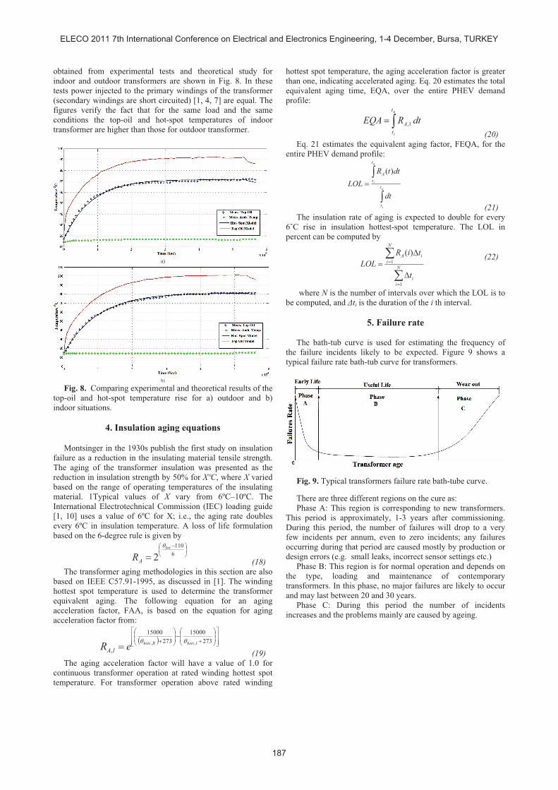
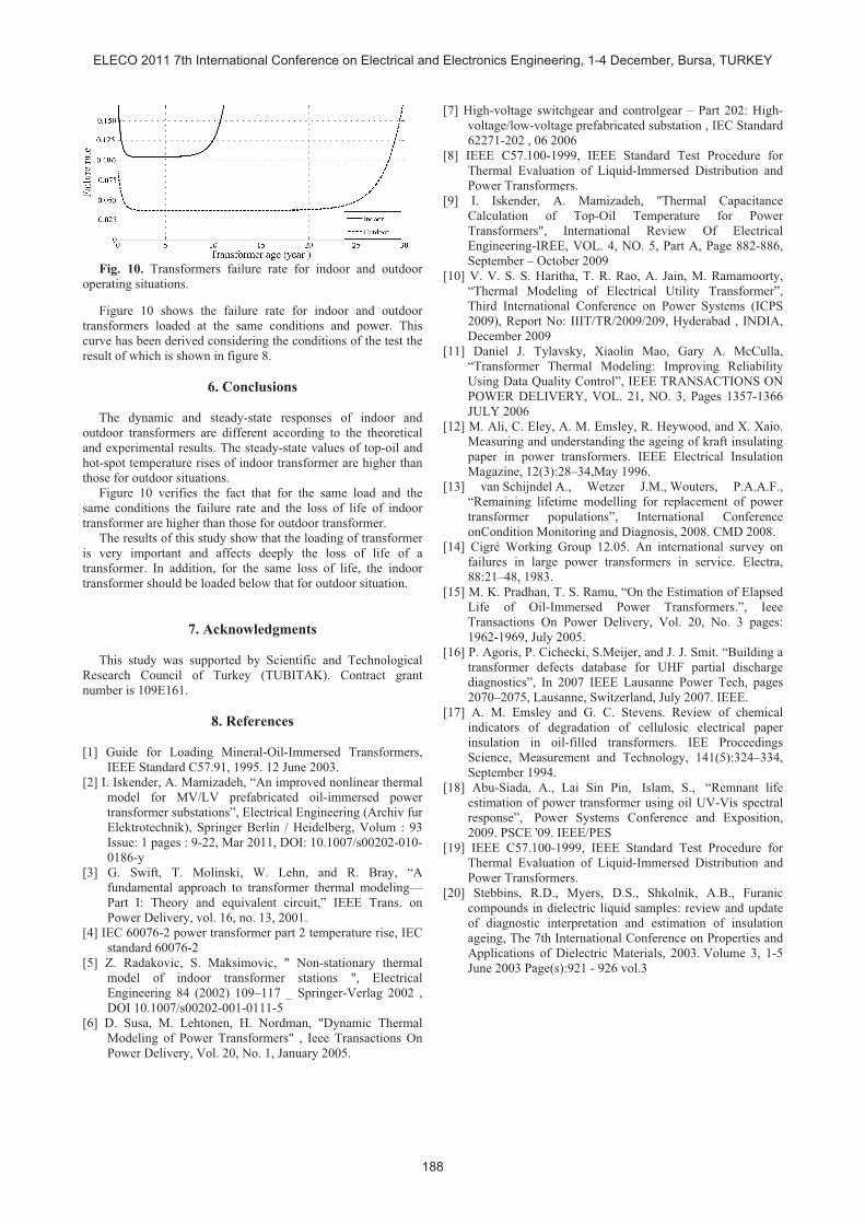
Evaluation and Comparing the Loss of Life for Outdoor and MV/LV Prefabricated Oil Immersed Power Transformer Based on Nonlinear Thermal Models Ali Mamizadeh 1 , and res skender 2 Electrical and Electronic Engineering Department, Engineering Faculty, Gazi University, Ankara, Turkey 1 [email protected], 2 [email protected]Abstract Power transformers are the most critical and expensive equipment in the field of transmission and distribution of electric energy. Any major fault in these units can cause not only catastrophic damage to various equipments but also cause interruption of electricity supply. These direct or indirect effects often lead to large economic losses. The most important parameter in transformers life expectancy is the insulation hot-spot temperature value which accelerates the rate of aging of the insulation. This Study proposes a life expectancy model for oil immersed power transformer using the hot-spot temperature based on transformer nonlinear hot-spot and top-oil temperature rise models. Since the thermal transfer is different for indoor and outdoor transformers considering their operating conditions, their thermal and loss of life models are different and are analyzed and compared in this study. Key words: loss of life, oil immersed transformers, thermal aging, indoor, outdoor 1. Introduction The insulation aging of transformers is an important parameter affecting their life expectancy. Insulation aging depends deeply on the insulation temperature, the humidity level, and the oxygen included in it [1]. The humidity level and the oxygen included in oil can be taken under control in the new designed oil immersed transformers. Therefore, the most important parameter that should be cared is the operating temperature of transformer. For this purpose, the study and deriving the thermal model of a transformer is getting more importance. The thermal model of a transformer is also important when it is aimed to manage the load profile of a power transformer [3, 5] and to program its loading. The insulation aging phenomenon has been well documented as a thermal deterioration process in the literature. The application of loading on a transformer, i.e., the load current in the transformer coils, results in heating and, consequently, reduction in the age of the transformer. Loading capability of power transformers is limited mainly by winding temperature [1]. One of important test that is applied on a transformer is the temperature rise test which is carried out under rated power and ambient temperature conditions. The average temperature of the winding should be less than the corresponding values given the International Standards such as IEC or IEEE. However the temperature of the winding is not uniform and the real limiting factor is actually the hottest section of the winding commonly called winding hot spot. This hot spot area is located somewhere toward the top of the transformer, and not accessible for direct measurement with usual methods. Recommendations in IEEE C57.94 guide are based on life expectancy of transformer insulation as affected by hot-spot temperature and time [5, 12]. The Permissible loading of transformers for normal life expectancy depends on different parameters such as; the design of the particular transformer, hot-spot temperature rise at rated load, temperature of the cooling medium, duration of the overloads, the load factor, and the altitude above sea level. Transformers are designed considering the ambient and the winding average temperature obtained from measuring the winding resistance. For proper design of transformer the hottest- spot temperature should be used as the limitation rather than the average winding temperature rise. 2. Insulation paper degradation The power transformer is a component operating in high voltage, high current, and consequently high power condition. Each aspect imposes its specific challenge on the transformer design. High voltage poses a need for dedicated insulation measures to prevent flashovers, especially during temporary over-voltages due to switching or lighting strokes. High currents are associated with high magnetic fields, which corresponds to strong electromagnetic forces, during high load and short-circuit situations. Though transformers are extremely efficient devices, the heat generated by the power losses must be disposed of the insulating medium in power transformers. Hence, the insulation must be capable of dealing with electric stresses, large electromechanical forces, and high temperatures [8, 14]. Paper-oil insulation is widely used in power transformers. Oil has an intrinsic high insulating strength and at the same time serves as cooling medium by either passive or active flow. The paper prevents electric bridging by contaminants left behind and serves as a mechanical barrier between the windings and winding layers. The paper is a critical factor in paper-oil insulation. Oil is easier to replace and its quality can be monitored. The paper insulating properties may be affected by displacement or by ageing. The insulating papers consist of cellulose chains with their average length expressed in the degree of polymerization (DP). The chemical formula of one cellulose unit, the monomer, is (C6H10O5)n [8]. The chemical structure of two connected cellulose rings, i.e. one cellobiose unit, is depicted in Figure 1. A practical value for the DP of unaged paper is 1000–1200. The paper tensile strength is a measure for the sensitivity to paper rupture. The tensile strength is directly related to the degree of polymerization of the insulating paper. If the mechanical strength of paper is reduced to 50% of the initial strength, its strength is considered to be in a ELECO 2011 7th International Conference on Electrical and Electronics Engineering, 1-4 December, Bursa, TURKEY 184
Transcript
Evaluation and Comparing the Loss of Life for Outdoor and MV/LV
Prefabricated Oil Immersed Power Transformer Based on Nonlinear Thermal
Models
Ali Mamizadeh1, and !res !skender2
Electrical and Electronic Engineering Department, Engineering Faculty, Gazi University, Ankara, Turkey