NREL-472-7015 • UC Catego: 1300 • DE94011890 Evaluation of a Liquid-Desiccan nhanced Heat-Pipe Air P nditioner Ahmad Pesaran Yves Parent National Renewable Energy Laborato Milton Meckler Meckler Energy Group Davor Novosel Gas Research Institute Prepared for the 1995 ASHRAE Winter Meeting, Chicago, Illinois ·� . ·��-· •. . •. , �- ·-· -- • National Renewable Energy Laboratory 1617 Cole Boulevard Golden, Colorado 80401-3393 A national laboratory of the U.S. Department of Energy managed by Midwest Research Institute for the U.S. Department of Energy under Contract No. DE-AC36-83CH10093 October 1994
Transcript
NRELffP-472-7015 • UC Category: 1300 • DE94011890
Evaluation of a Liquid-Desiccan nhanced Heat-Pipe Air P nditioner
Ahmad Pesaran Yves Parent National Renewable Energy Laboratory
Milton Meckler Meckler Energy Group
Davor Novosel Gas Research Institute
Prepared for the 1995 ASHRAE WinterMeeting, Chicago, Illinois
.&!·�..... ·��-· •. . •. , �-·-· -
•
National Renewable Energy Laboratory 1617 Cole Boulevard Golden, Colorado 80401-3393
A national laboratory of the U.S. Department of Energymanaged by Midwest Research Institute for the U.S. Department of Energyunder Contract No. DE-AC36-83CH10093
October 1994
NOTICE
This report was prepared as an account of work sponsored by an agency of the United States government. Neither the United States government nor any agency thereof, nor any of their employees, makes any warranty, express or implied, or assumes any legal liability or responsibility for the accuracy, completeness, or usefulness of any information, apparatus, product, or process disclosed, or represents that its use would not infringe privately owned rights. Reference herein to any specific commercial product, process, or service by trade name, trademark, manufacturer, or otherwise does not necessarily constitute or imply its endorsement, recommendation, or favoring by the United States government or any agency thereof. The views and opinions of authors expressed herein do not necessarily state or reflect those of the United States government or any agency thereof.
Available to DOE and DOE contractors from: Office of Scientific and Technical Information (OSTI) P.O. Box 62 Oak Ridge, TN 37831
Prices available by calling (615) 576-8401
Available to the public from: National Technical Information Service (NTIS) U.S. Department of Commerce 5285 Port Royal Road Springfield, VA 22161 (703) 487-4650
... t • .) Printed on paper containing at least 50% wastepaper and 10% postconsumer waste
EVALUATION OF A LIQUID-DESICCANT-ENHANCED HEAT-PIPE AIR PRECONDITIONER
Ahmad A. Pesaran and Yves 0. Parent National Renewable Energy Laboratory, Golden, CO
Milton Meckler Meckler Energy Group, Encino, CA
Davor Novosel Gas Research Institute, .Chicago, IL
ABSTRACT Recent increases in outside ventilation rates from 5 fr /min
(cfm) per person to 15-20 cfm/person, in compliance with ASHRAE Standard 62-89, will impose additional sensible and latent loads on buildings. The concept of a desiccant-enhanced heat pipe discussed here has the potential to provide an efficient preconditioner for the ventilation air. This paper presents the results of an experimental evaluation of enhancing the dehumidification performance of a heat-pipe heat recovery unit by incorporating a liquid-desiccant dehumidification function. A commercial heat-pipe thermal recovery unit with an indirect evaporative-cooling feature was modified by incorporating a liquid-desiccant contacting/recirculation loop on the supply-air side. Two liquid desiccants, lithium chloride (LiCl) and triethylene glycol (TEG) solutions, were tested in this device. The cooling capacity of the heat-pipe with desiccants increased 20%-40%. The cooling performance of the heat-pipe system using TEG was about 10% less than when using LiCl. The efficiency of the dehumidification operation was estimated to be only on the order of 40%-50% of the equilibrium dehumidification potential because of less than optimal gas/liquid contact. Further research and development work could improve this performance into the 80%-90% range. The outcome suggests that the liquid-desiccantenhanced heat-pipe device could be a viable system for preconditioning ventilation air.
INTRODUCTION Because of concerns about indoor air quality in buildings and
issues related to "sick building syndrome," the American Society of Heating, Refrigerating, and Air-Conditioning Engineers (ASHRAE), in a recent industry standard (Standard 62-89, Ventilation for Acceptable Indoor Air Quality), recommended increasing the outdoor air ventilation rate from 5 cfm per building occupant to 15-20 cfm per occupant. This additional outdoor air must be conditioned to the desired comfort level of humidity and temperature before being supplied to the occupied spaces. This conditioning of the ventilation air requires additional equipment and energy. When the new standard is adopted, the value of the equipment necessary to retrofit the existing commercial building systems is estimated to exceed $500 million distributed over the
next several years. New products are needed to condition this ventilation air in an energy-efficient and cost-effective way. Furthermore, this new equipment must not use chlorofluorocarbons (CFCs), which are believed to contribute to depleting the earth's ozone layer and whose production is banned by year 2000.
Conditioning of ventilation air requires temperature and humidity control. Furthermore, if the outdoor air is more polluted than indoor air, the ventilation air must also be cleaned. In the cooling season, the temperature of the outdoor air needs to be lowered. This could be accomplished by conventional vapor-compression units or by exchanging heat with cool exhaust air using thermal recovery units such as heat wheels or heat-pipe air-to-air heat exchangers. In areas with medium-to-high outdoor humidity, dehumidification is required, and heat exchange alone may not work. Desiccants could be used in this situation to add dehumidification capability to thermal recovery units (Meckler, 1989).
The objective of this study was to test the feasibility of a liquid-desiccant-enhanced heat-pipe thermal recovery unit for preconditioning ventilation air. In this paper, we present a summary of the concept, the test procedure, and test results. Details of the study are given by Parent et al. (1993).
BACKGROUND A heat pipe is, in its simplest form, a closed heat-transfer
device that relies on vaporizing and condensing a working fluid to transport large quantities of energy at near-isothermal conditions. Figure 1 shows a schematic of a heat-pipe device; a bank of heat-pipe tubes assembled together can form a heat-pipe unit. Commercially available heat-pipe thermal energy recovery units can reclaim cooling energy during the summer and heating energy during the winter. The exchange takes place between exhaust air and supply air streams of a building (Figures 2). The working section of the device is composed of a bank of heat-pipe tubes with one end in the supply air stream and the other end in the exhaust air stream. In some commercial units, a cooler sink is provided in summer operation by spraying water on the exhaust side to indirectly and evaporatively cool the supply air (Figure 2).
Conventional heat-pipe thermal energy recovery units only deal with sensible cooling. In the present concept we studied, a concentrated liquid desiccant is sprayed on the heat-pipe fins on the supply side to dehumidify the air (see Figure 3). The heat of absorption released during dehumidification is rejected to the exhaust side through the heat-pipe tubes. The liquid desiccant becomes more effective, because the heat of absorption is transferred away at the source, thus reducing the sorption temperature and positioning the operation in a more favorable portion of the desiccant/moisture equilibrium map. The other advantage of this approach, expected to reduce component costs, is the integration of two conventional, separate processing steps (dehumidification and temperature change of the supply air stream) into one combined effect. The diluted liquid desiccant is reactivated for reuse by thermal energy input in a regenerator.
EXPERIMENTAL APPROACH Our philosophy for testing the feasibility of the concept was
to adapt and modify an existing commercially available unit and to test it under conditions comparable to those found "in the field."
Test Unit A commercially available heat-pipe thermal energy recovery
unit equipped with indirect evaporative cooling was purchased for the study. A schematic of the standard device configuration is shown in Figure 2. Water can be sprayed onto the contacting matrix from both the front (parallel to air flow) and top (perpendicular to air flow) of the matrix. At design conditions, the unit is capable of reclaiming 0.9 ton (3.52 kW) of cooling for summer conditions and 0.5 ton (1.76 kW) for winter conditions with an air flow rate of 600 cfm (283 Lis). Figure 2 is a top view of the device, with the heat-pipes operating in a horizontal position. The working section of the test unit is composed of a bank of 48 heat-pipe aluminum tubes (5/8-inch outer diameter) in a pattern of six staggered rows and an integral part of a section of corrugated aluminum fins set 11 per inch. The resulting exchange surface matrix on both ends of the heat-pipe structure fills the duct passage of the supply and exhaust air streams, respectively. The dimensions of the contact volume thus formed are a 12-in. (0.305-m) height, 11-in. (0.279-m) width, and 8-in. (0.203-m) depth in the direction of flow. The true unobstructed width of the air duct is 10 in. (0.254 m).
Minor modifications were incorporated into the unit at the time of manufacture. For example, nozzles were installed to distribute liquid desiccant onto the fin matrix on the supply side, and mist eliminators were installed to minimize the possibility of desiccant entrainment. The enclosure walls from both sides were made removable for easy access to all internal components. The standard tilt action for the heat-pipe component was eliminated; thus, the conductance of the heat-pipe exchanger would remain fixed at whatever value was achievable in the set horizontal operating position. This would reduce the flexibility for winter operation, which was not of interest to us. Separate liquid distribution systems and sumps were provided to handle water on the exhaust side and liquid desiccant on the supply side. We replaced the water-side 1 /12-horse-power (hp) pump (1 gpm) with a larger unit (1 /8 hp) to allow flows up to 2 gpm (0.126 Us). We installed a 3/4-hp pump for handling viscous liquid desiccants up
2
to 2 gpm (0.126 Us). We added a partition of closed-cell foam between the two sumps to minimize the exchange of moisture between these two parts of the system. A schematic of the modification to the standard device is presented in Figure 3. To regenerate the liquid desiccant for the purpose of these experiments, we used a regeneration subsystem supplied by a major liquid desiccant system manufacturer.
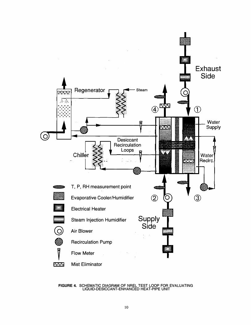
Experimental Test Loop Figure 4 is a simplified overall schematic of the test loop
located at the National Renewable Energy Laboratory for testing the desiccant-assisted heat-pipe device. The purpose of the test loop is to supply controlled air streams at a desired flow rate, temperature, and humidity to the device under testing. Furthermore, the dry-bulb temperature and the dew-point temperature (of the incoming and outgoing air streams) are measured and monitored to assess the performance of the test device under such conditions. Copper-constantan thermocouple wires and chilled-mirror hygrometers are used to measure the air dry-bulb and dew-point temperatures, respectively. Pressure drops are measured using capacitance-type pressure transducers. The uncertainties of the measuring instruments are as follows: 0.5°F (0.2°C) in dry-bulb temperature, 0.7°F (0.3°C) in dew-point temperature, and 0.03 inches water (7.5 Pa) in pressure drop. The mass flow rate of each air stream is calculated (with an uncertainty of <3%) using the pressure drop across nozzles upstream of the heat-pipe, and the absolute pressure is measured using a mercury barometer (with an uncertainty of <0.2%). The humidity ratio at each measuring station is calculated (with an uncertainty of <3%) using the dew-point temperature and the absolute pressure at that point. The desiccant concentration of selected samples is measured using a densimeter. The water mass flow rate for spray on the exhaust side is measured using a rotameter, and the desiccant mass flow rate for spray on the supply side is measured using a turbine flow meter. A computercontrolled data acquisition system monitors and collects the data (air dry-bulb and dew-point temperatures, pressure drops, air mass flow rates, and liquid mass flow rates).
For the SUPPLY SIDE, room air is pulled into the preconditioning section by an electric blower. The incoming air temperature and moisture content can be controlled using an electric heater, direct steam injection, and direct-contact evaporative cooling. Air contacts liquid desiccant in the fin matrix of the heat-pipe energy recovery unit. A coarse mist eliminator is located immediately after the fin pack to limit entrainment of desiccant droplets. An additional mist eliminator with finer mesh was built into the exhaust duct of the device. The dry-bulb and dew-point temperatures of the air stream are measured at the inlet to the test device. Once the air is through the device and at the outlet, the air stream dry-bulb and dew-point temperatures are measured once again. The air is then vented to the outside of the building.
On the SUPPLY SIDE, the device interacts with two semi-closed circulation loops of liquid desiccant. One pumped loop draws liquid desiccant from the bottom of the device's sump and returns a portion of this volume directly to the sump to ensure mixing of the sump volume, while the remaining circulating volume is sent through a cooled heat exchanger and on to the spray heads of the dehumidifier section of the device. The flow
rate to the spray manifold is controlled. Cooling in the heat exchanger is ensured by circulating cold water from a chiller. The second desiccant circulating loop interconnects the device to the regenerator. Desiccant overflows from the device's sump and moves by gravity toward the regenerator sump.
At the regenerator, a pump draws liquid from its sump, sends a small amount of liquid back to the device's sump at a controlled flow rate, and sends the remainder of the flow volume to a steam-heated plate heat exchanger and onto the spray head of the regenerator. Regeneration is accomplished by counter-current direct contact of room air (up flow) with hot desiccant solution sprayed onto a packed bed of commercial column packing. The liquid desiccant is heated in a fin-and-plate heat exchanger using steam. Control of the heat input is based on liquid level in the sump.
Air handling on the EXHAUST SIDE is similar to that of the supply side. Here, inside air, outside air, or a blend of both is drawn in by a blower. The incoming air temperature and moisture content can be adjusted and controlled as described above. The dry-bulb and dew-point temperatures of the air stream are also monitored at the inlet to the test device using the type K thermocouples and chilled-mirror hygrometers, respectively. Once the air is through the device and at the outlet, the air stream drybulb and dew-point temperatures are measured once again. The air is then vented to the outside of the building.
On the EXHAUST SIDE, only one circulation loop assures flow and distribution of the water for the evaporative cooler operation. The sump is automatically replenished with water by using a float valve. A small submersible pump draws water from the sump, feeds a direct-return line for mixing purposes, and also feeds the spray manifold of the evaporative cooler. The water spray flow rate is monitored and controlled.
Testing Program Three types �of operating conditions were considered (see
Table 1). First, we operated without spraying any desiccant on the supply side, and with and without water spraying on the exhaust side. This data set established the baseline and allowed comparison to conventional-use design specifications. Tests #LiCl.l through #LiC1.8 and #TEG. l through #TEG.6 of Table 1 represent such conditions. Second, we addressed the use of a lithium chloride (LiCI) solution as desiccant. In this set, operation both with and without water on the exhaust side was considered. Variations in inlet temperature and moisture content on supply and exhaust sides were investigated. Tests #LiC1.9 through #LiC1.16 deal with these operating conditions. Finally, we operated with triethylene glycol (TEG) solutions. Tests #TEG.7 through #TEG. l6 cover these particular operating conditions.
Another purpose of the testing program was to observe the operation of the various components of the system to identify possible issues and recommend improvements. The commercial device was not specifically designed to handle viscous liquid desiccants such as LiCl and TEG in the most optimal manner (such as fin spacing and flow distribution) to allow maximum liquid coverage.
Air inlet flow rate could be varied but most tests were conducted at == 630 acfm (297 Lis) (Denver elevation: 5700 ft, 0.81 atm). Similarly, the flows of both liquid desiccant and water to the contacting sections were set by visual inspection of
3
adequate spray pattern at the nozzles. These conditions correspond to flow rates of 2 gpm (0.125 Lis) for water and 1.8 gpm (0.108 Lis) for LiCl desiccant. In the case of TEG, the viscosity and pressure drop in the nozzle line limited our operation to a flow rate of 1-1.5 gpm (0.063-0.095 Lis). The return flow rate of the desiccant from the regenerator to the heat-pipe device sump could be adjusted and maintained at flows up to 2 gpm (0.125 Lis).
Data were obtained for 32 different tests, as recorded in Table 1. Details of these tests are given in Parent et al. (1993). Table 2 presents a selection of parameters that were kept essentially constant throughout these tests. Inlet air conditions for the supply and exhaust sides are selected near Air Conditioning and Refrigeration Institute (ARI) conditions for the Denver elevation. The essential data describing differences between all the tests completed are presented in Table 1. A quick overview of performance is also given in this table by tabulating the energy transfer between the supply side and the exhaust side as attributable to the heat-pipe bundle. These values are expressed in equivalent tons of cooling.
RESULTS AND DISCUSSION
Air Flow Pressure Drop Across the Test Unit Measurements of pressure drop across the device (including
heat-pipe bundle, coarse mist eliminator, and inlet and outlet duct transition sections) with and without liquid flow yielded the following results for air flows of 628 acfm:
No liquid flows, same air flow rates on both sides, same temperature, same humidity,
Supply side �P= 0.79 in. HP Exhaust side �P= 0.85 in. HP
With the uncertainty of less than 0.03 inches water, these values are comparable and suggest the system is relatively well balanced in terms of resistance to air flow.
The presence of liquid flow across the fins did result in an increase of �P, as evidenced in all tests; for example,
Supply side �P= 1.20 in. HP@ 1.8 gpm LiCl 37 wt% Supply side �P= 1.17 in. Hp @ 1.5 gpm TEG 95 wt% Exhaust side �P= 1.08 in. HP @ 2.0 gpm water
Overall Performance-Without Desiccant In operation without desiccant, the heat-pipe device performs
at least as well as rated by the manufacturer. Tests #LiCI. l through #LiC1.8 and #TEG. l through #TEG.6 were all performed without desiccant. In the evaporative cooler mode, the device delivers between 0.9 and 1.2 tons of cooling to the incoming supply stream. The improved performance (over manufacturer's specification) can be associated with the increased water flow rate at the evaporative cooler and to the reduced air flow on both sides of the heat-pipe. This performance was apparently unaffected over a relatively wide range of moisture contents for both supply and exhaust sides.
Comparing test conditions of #LiC1.7 and #TEG.6, one would expect a higher energy transfer rate with test #TEG.6 which has
drier air on the inlet of the EXHAUST SIDE. However, the energy transfer rate for test #TEG.6 is about 0.05 ton less. Such discrepancies in energy transfer are likely associated with the unsteady behavior of the system during the data acquisition for these sets. Indeed, although the desiccant was not being sprayed on the dehumidifier side, it was still being recirculated between the regenerator and the sump. Some variation in the temperature of the liquid desiccant in the sump may have contributed to energy transfers to either side of the device.
In the evaporative cooler mode of operation, the device performs as a relatively efficient sensible heat exchanger for the supply side. Figure 5 shows a typical example of the psychrometric process for this mode of operation. Note that points I and 3 on the psychrometric charts apply to the exhaust side process and correspond to Inlet and Outlet as indicated on Figure 3, respectively. Similarly, points 2 and 4 apply to the supply side and correspond to Inlet and Outlet, respectively.
Overall Performance-With Desiccant The operation with desiccants included LiCl tests and TEG
tests. The results of each group of tests are discussed below.
LiCl Tests-Tests #LiC1.9 through #LiC1.16 were conducted with LiCl as desiccant. Two of these, tests #LiC1.9 and #LiC1.15, were carried out without water (i.e., the evaporative cooler function was turned off). As discussed earlier, energy transfer is much lower in such a case. The strong effect of evaporative cooling can again be observed between tests #LiC1.9 and #LiCl. l 0, where the additional cooling enhances the desiccating power of the liquid from 17 grains/lb to 21 grains/lb.
Note that two factors could limit accuracy of the energy balances: (1) large masses of water and desiccant in the respective sumps, and (2) the unsteady behavior of the system (such as the off/on cycle of the regenerator) during data acquisition. These factors may lead to some discrepancies in the heat transfer rates and may increase uncertainty (about ±15%). For example, the observed behavior from tests #LiCl.II through #LiCl.I3 was not expected; we expected a steady decrease with an increase in the inlet exhaust-air humidity ratio.
Tests #LiC1.12, #LiC1.13, and #LiC1.14 constitute the most representative Inlet conditions for the system. Performance is on the order of 1.7 tons for #LiC1.1 2 and #LiC1.13, in which the exhaust inlet moisture content is increasing. Performance falls off to 1.5 tons of cooling as the exhaust inlet moisture content climbs to almost 50 % relative humidity (RH), thus reflecting the decrease in evaporative cooling capacity. Test #LiC1.16 is the operation of the system for several hours during which conditions were maintained constant to observe steady-state response. The performance value is slightly lower than in the previous tests, most likely because of operation at a reduced desiccant flow rate (1 gpm). The specifics of this test are presented in Figure 6. Overall, the heat-pipe bundle transfers 30% to 40% more heat when operating with LiCl desiccant. The nominal concentration for the LiCl solution in these tests was 37 wt% (LiCl).
Lithium chloride solutions could be corrosive and incompatible with ordinary metals. Coating or replacing these metals with specialty metals or plastics could increase the cost of the system.
4
TEG Tests-Tests #TEG.7 through #TEG.16 represent operations using TEG as the desiccant. Two of these tests, #TEG.7 and #TEG.11, were carried out without water (i.e., the evaporative cooler function was turned off). They show that the resulting energy transfer is much lower. Comparing results of tests conducted without any TEG (e.g., tests #TEG.2, #TEG.3, and #TEG.5) with those conducted with TEG (e.g., tests #TEG.9, #TEG.IO, and #TEG.13 through #TEG. l6) shows that heat-pipe bundles transfer about 20% to 30% more heat when operating with TEG desiccant. For the TEG tests, the nominal concentration of the solution was 95 wt% (TEG). Test #TEG. I6 operated for several hours to observe steady-state response. The performance value, in terms of latent load on the desiccant, is slightly lower than in previous tests. Over the period of several hours of operation for test #TEG. l6, the regenerator loop operation stabilized at a slightly higher moisture content in the solution. Specifics for this test are presented in Figure 7.
All tests using TEG show lower heat-pipe duty (about 10% on the average) than in the case of the LiCl tests. The two longrun tests (#LiC1.16 and #TEG.16), which reduce unsteady behaviors through averaging, show lower heat duty for TEG. Figure 8 is a typical comparison of the performance of the heatpipe bundle for three cases (with LiCl, TEG, and without desiccant) for similar conditions. The cooling performance of the heat-pipe with TEG (at 1.4 tons) is about 10% less than that of the heat-pipe with LiCl (at 1.5I tons) and about 30% more than that of the heat-pipe without any desiccant. The lower heat transfer rate and associated lower moisture removal rate by TEG could be attributed to less efficient contact between the desiccant and supply air stream. Higher viscosity of TEG, leading to poor distribution of the liquid in the contacting fin matrix, could be a cause of less-efficient exchange. In addition, the specific sorption energy of water by TEG is less than by LiCl. Attempts at improving mass transfer in the dehumidifier section by increasing the desiccant flow rate (tests #TEG.9 compared with #TEG .I 0 and #TEG. l5) yielded no improvement. These observations confirm the inadequate distribution of liquid and inadequate design of the contacting section (tubes/fins spacings) for liquids significantly different than water.
A potential advantage of use of TEG solutions is their capability of cleaning air by removing volatile organic compounds (Hines and Ghosh, 1992). Although TEG has a very low volatility, it may be carried over by the supply air and later condensed on cold surfaces in a building; engineering solutions exist to prevent this. Higher-molecular-weight organic liquids such as polyethylene glycols could also be used instead.
Both Desiccants-Because of poor mass transfer, neither desiccant exhibits its maximum dehumidification capacity. The supply side outlet air could have been much drier if it was approaching equilibrium. In our tests, LiCl and TEG exhibited only 50% and 40% of their dehumidification potential, respectively. By improving mass transfer rate (e.g., through improved spraying and flow distribution, improved fin configuration and spacing, and increased contact area), it is feasible to achieve 85% of the dehumidification potential of the desiccant, which could result in drier air and higher latent-load removal. Improving the mass transfer rate will be a challenge for further research and development.
For each experiment, we have estimated the heat added by the regenerator and approximated heat removed by the chiller based on mass flow rates and temperature changes. For example, for test #LiCl.16 the heat added by the regenerator was 4750 Btu/h and the heat removed by the chiller was 1.0 ton. Note that the heat-pipe energy transfer rates shown in Table 1 are calculated by excluding the contribution of cooling by the chiller. Because the desiccant volume and the size of the regenerator in the system was larger than one would actually use for a practical unit, we did not attempt to estimate any coefficient of performance (COP) for the system. Our earlier analysis (Parent et al., 1993) indicates that for a regeneration latent COP of 0.55, 1.0, and 1.6, the thermal COP of the tested TEG-enhanced heat-pipe would be 0.93, 2.06, and 3.74, respectively. The latent COP is defined as latent load removed divided by thermal energy input to the regenerator. The thermal COP could be defined as cooling capacity (sensible and latent) removed divided by the thermal energy input. Note that both these COPs exclude any electrical energy for pumps and fans. A latent COP of 0.55 is achievable with existing standard regeneration equipment. Regenerators with latent COPs of 1 .6 need to be developed and may require a more sophisticated regeneration approach such as staging.
Comparison with Enthalpy Wheels As discussed earlier, the liquid-desiccant-enhanced heat-pipe
device could be used for preconditioning ventilation (outside) air. Using a preconditioner to treat outside air rather than using the main vapor-compression/air-conditioner (VC/AC) system could save energy costs. There are a number of devices that could be used for treating outside air. Enthalpy wheels, considered among efficient commercially available heat-recovery units, could be used for treating outside air (Semco, 1989). The tested LiClenhanced heat-pipe unit, in its present configuration and without further improvements in gas/liquid contacting operation, performed in a comparable manner to a high performance (80%effective) commercially available rotating enthalpy wheel.
We have compared the energy costs of a VC/AC system with and without enthalpy wheels or TEG-enhanced heat-pipe preconditioners (Parent et al., 1993). Because either the enthalpy wheel or the TEG-enhanced heat-pipe is used as a preconditioner, their ultimate performance comparison should be made when they are integrated with a VC/AC treating the recirculated air as shown in Figure 9. Parent et al. (1993) compared energy needs for conditioning 1000 cfm of outside air in Denver from the ARI design air condition to a supply design air condition of 55°F and 80% RH. Three options to provide the 5.82 tons of cooling were compared: a VC/AC, an 80%-efficient enthalpy wheel integrated with a VC/AC, and an 85%-efficient TEG-enhanced heat-pipe integrated with a VC/AC. The latent COP for TEG regeneration was assumed to be 1.6. The electric COP of the VC/AC was assumed to be 3 in all three options. The electric energy consumption for the preconditioners was estimated based on parasitic power needs. The parasitic loss for enthalpy wheels was based on air-side pressure drops from manufacturer's literature (Semco, 1989). The parasitic loss for the desiccant heat-pipe was based on (1) measured pressure drops on air sides and (2) the power needs to pump and distribute water and liquid desiccant. Details of the analysis including assumptions could be found in Parent et al. (1993).
5
Figure 10 compares hourly operating energy costs (in cents per hour) for the three options discussed above. Natural gas, with a burning efficiency of 95%, was used for providing regeneration energy to the TEG heat pipe. Clearly the operating energy costs for the VC/AC-only option is higher than the other two preconditioner options. The operating energy cost of the VC/AC plus TEG-enhanced heat-pipe option is less than that of VC/AC plus enthalpy wheel at low gas prices and moderate-to-high electricity prices. The liquid-desiccant-enhanced heat-pipe could offer energy cost savings over the enthalpy wheel. Although a liquid-desiccant-enhanced heat-pipe may be more complex than an enthalpy wheel, it has the advantage of removing pollutants from the air (Hines and Ghosh, 1992).
CONCLUSIONS AND RECOMMENDATIONS We tested the feasibility of enhancing the dehumidification
capability of a heat-pipe thermal recovery unit by contacting with a liquid-desiccant for preconditioning supply air. The heat-pipe unit incorporated indirect evaporative cooling. Data showed that the heat-pipe with TEG on the supply side provided about 30% more cooling capacity than the heat pipe with no desiccant. The cooling performance of the heat pipe with lithium chloride was even better, about 40% more than the system with no desiccant. The liquid-desiccant-enhanced heat pipe transfers both latent and sensible heat between the streams in a very compact and mechanically simple system. No mechanical (CFC) refrigeration is involved, and the system would easily lend itself to retrofit situations where increases in ventilation rates are anticipated.
Based on equilibrium considerations, we found that in the conducted tests only about 40% to 50 % of the dehumidification potential of liquid desiccants is being used. This was attributed to poor mass transfer rates because of poor distribution of the desiccant in the flow channels and insufficient contact area between heat-pipe surfaces, the liquid desiccant, and the air stream. Further research and development is needed to improve the mass transfer rate through improving flow distribution and fin spacing, increasing the contact area, and thus achieving higher efficiencies of up to 85% the dehumidification potential.
The tested liquid-desiccant-enhanced heat-pipe system showed comparable performance to an 80%-effective enthalpy wheel. With further improvements in design of the dehumidifier section, the latent load handled could be doubled, and the performance of the TEG heat pipe could exceed the performance of an enthalpy wheel. Estimates indicated that at low-to-moderate gas prices and moderate-to-high electricity prices, the desiccantenhanced heat pipe integrated with a vapor-compression air conditioner is less expensive to operate than an enthalpy wheel integrated with an air conditioner when the latent (or regeneration) COP is above 1.4. The analysis did not consider the potential use of TEG for removing pollutants such as VOCs.
The data generated from the existing experiment clearly show that the integration of direct-contact dehumidification by means of a liquid-desiccant (liquid-desiccant-enhanced heat-pipe) is feasible. Both sensible and latent loads could be removed without the use of CFC or HCFC refrigeration. The liquid-desiccantenhanced heat-pipe could be a viable HV AC component for preconditioning outside ventilation air.
Based on the promising results achieved in this study, we recommend further development of the liquid-desiccant-enhanced
heat-pipe preconditioner for treating ventilation air. Efforts to improve the dehumidification capability of the desiccant heat-pipe to up to 85% of equilibrium dehumidification potential are recommended. This might be achieved by improving the mass transfer process through improving the desiccant flow distribution between heat-pipe fin channels and also extending the finned matrix in the direction of air flow.
Engineering solutions to avoid potential carryover of TEG in the supply air because of its low volatility need to be tested and evaluated. Higher-molecular-weight liquid desiccants such as polyethylene glycols should be evaluated for this application. Another important component that was not studied here is the desiccant regenerator. To compete successfully with other preconditioners, the liquid-desiccant-enhanced heat-pipe device requires an efficient regenerator. Investigations for designing efficient regenerators such as multi-stage or vapor-compression distillation devices are recommended.
Improved liquid-desiccant-enhanced heat-pipes and regenerators need to be designed, fabricated, and tested in the laboratory. Compact designs for the liquid-desiccant-enhanced heat pipe as an add-on component to the existing packaged units need to be fabricated and field tested.
ACKNOWLEDGMENTS The experimental work of this project was funded by the Gas
Research Institute under Contract No. 5091-246-2247. The analysis for comparing desiccant enhanced heat pipe with enthalpy wheels was supported by the Director's Development Fund of the National Renewable Energy Laboratory under Task No. 07472042. We appreciate the assistance of Ed Hoo and Doug Powell of NREL in assembling the test apparatus and conducting the tests.
REFERENCES Hines, A.L., and T.K. Ghosh, 1992, Investigation of
Co-sorption of Gas and Vapors as a Means to Enhance Indoor Air Quality- Phase 2: Air Dehumidification and Removal of Indoor Pollutants by Liquid Desiccants, GRI-92/0157.3, Gas Research Institute, Chicago, IL.
Meckler, M., 1989, "Integrated Desiccant Cold Air Distribution System," ASHRAE Transactions, Vol. 95, Pt. 2.
Parent, Y., A.A. Pesaran, and M. Meckler, December 1993, Evaluation of Dehumidifiers with Polymeric Liquid Desiccants, GRI-93/0194, Gas Research Institute, Chicago, IL.
TEST CONDITIONS AND RESULTING HEAT-PIPE TRANSFER LOADS
SUPPLY AIR Inlet
EXHAUST AIR Inlet
LIQUID F!rOW RATE
ENERGY TRANSFER
Test#
ID
LiCI.l
moisture content
lbnb f%RHla
.0043 19 @ 75.F
moisture content
lbnb
.0043
f%RHlb
19
water desiccant
Jgpml f�roml
0.0 0.0
heat pipec
ftons coolin!! 1 n/a
LiCI.2 .0046 11 .0045 20 0.0 0.0 0.41
LiCI.3 .0045 10 .0046 20 2.0 0.0 1.27
LiC1.4 .0044 10 .0044 20 2.5 0.0 1.28
LiCI.5 .0120 28 .0051 23 2.0 0.0 1.26
LiCI.6 .0201 46 .0057 25 2.0 0.0 1.30
LiCI.7 .0209 48 .0066 29 2.0 0.0 1.41
LiCI.8 .0194 48 .0093 41 2.0 0.0 1.33
LiCI.9 .0134 29 .0060 26 0.0 1.8 0.35
LiCI.IO .0125 29 .0059 26 2.0 1.8 1.51
LiCI.l1 .0184 42 .0062 27 2.0 1.8 1.61
LiCI. l2 .0188 43 .0068 30 2.0 1.8 1.73
LiCI . l3 .0182 42 .0082 36 2.0 1.8 1.75
LiCI.l4 .0183 42 .0110 48 2.0 1.8 1.51
LiCI.15 .0113 26 .0059 26 0.0 1.8 0.33
LiCI. l6 .0184 43 .0116 51 2.0 1.0 1.41
TEG.1 .0180 42 .0115 50 0.0 0.0 0.42
TEG.2 .0186 42 .0116 51 1.0 0.0 0.98
TEG.3 .0178 41 .0116 49 2.0 0.0 1.07
TEG.4 .0181 42 .0076 34 0.0 0.0 0.46
TEG.5 .0184 42 .0080 35 1.0 0.0 0.95
TEG.6 .0186 43 .0083 36 2.0 0.0 1.28
TEG.7 .0179 41 .0117 51 0.0 1.0 0.55
TEG.8 .0176 41 .0116 50 1.0 1.0 0.83
TEG.9 .0182 42 .0115 51 2.0 1.0 1.40
TEG.10 .0183 42 .0116 51 2.0 1.5 1.37
TEG.11 .0180 42 .0086 38 0.0 1.0 0.48
TEG.12 .0177 42 .0089 40 1.0 1.0 0.97
TEG.13 .0173 40 .0091 40 2.0 1.0 1.32
TEG.14 .0178 41 .0118 52 2.0 1.0 1.43
TEG. l5 .0181 42 .0121 54 2.0 1.5 1.39
TEG.16 .0179 42 .0115 51 2.0 1.0 1.34
a: at 95°F (35°C)., unless otherwise specified Air flow rates are 628 acfm b: at 75°F (23.9 C), unless otherwise specified c: energy transferred by the heat-pipe oundle d: 0.0 means no water or desiccant sprayed on exhaust or supply sides, respectively
7
TABLE 2
SAMPLE OF NOMINAL OPERATING CONDITIONS FOR THE TESTS CONDUCTED
SUPPLY SIDE EXHAUST SIDE
INLET Air Temperature
INLET Air Mass Rate 37.4 lb/min (0.283 kg/s)
Water Spray Rate*
Desiccant Spray Rate* 1-1.8 gpm (228-408 Lis)
Desiccant Return Rate* 1 .4-1.8 gpm (318-408 Lis)
Desiccant Concentration* 37 wt% LiCl, 95 wt% TEG
Chiller Temperature
*if in use
8
Heat Input
Adiabatic section
Heat Output
Container
FIGURE 1. SCHEMATIC DIAGRAM OF A SIMPLE HEAT-PIPE
Exhaust Air INLET
• 1111Supply Air OUTLET
Exhaust Air OUTLET
1111 •
Supply Air INLET
FIGURE 2. SCHEMATIC DIAGRAM OF HEAT-PIPE THERMAL RECOVERY UNIT WITH INDIRECT EVAPORATIVE-COOLER FUNCTION
Exhaust Air INLET
Supply Air OUTLET
Supply Air INLET
FIGURE 3. SCHEMATIC DIAGRAM OF "LIQUID-DESICCANT-ENHANCED" HEAT-PIPE THERMAL RECOVERY UNIT
9
�
• • @ �
� E2iSI
Regenerator Steam
Desiccant Recirculation
Loops
T, P, RH measurement point
Evaporative Cooler/Humidifier
Electrical Heater
®
Steam Injection Humidifier Supply Side
Air Blower
Recirculation Pump
Flow Meter
Mist Eliminator
FIGURE 4. SCHEMATIC DIAGRAM OF NREL TEST LOOP FOR EVALUATING LIQUID-DESICCANT-ENHANCED HEAT-PIPE UNIT
ExhausSide
@
t
10
Psychrometric Chan lor Altitude 5700 loot Pressure: 24.26 in. Hg Heat Pipe Thermal Recovery Unit Tell #: TEG.6
Entering Supply Air Leaving Supply Air from Tested Heat Pipe without Desiccant Leaving Supply Air from Tested Heat Pipe with LiCI Leaving Supply Air from Tested Heat Pipe with TEG
FIGURE 8. PSYCHROMETRIC PROCESS COMPARING HEAT-PIPE OPERATION WITHOUT DESICCANT (TEST #TEG.3), WITH LiCI (TEST #LiCI.14) AND WITH TEG (TEST #TEG.6)
12
Exhaust Air Preconditioner
Return Air
FIGURE 9. SCHEMATIC OF AN INTEGRATED PRECONDITIONER WITH A VAPOR-COMPRESSION/ AIR-CONDITIONER (VC/AC) SYSTEM
90
80
70
:2 60 -G. --Ill -Ill 50 0
u >-Cl ... 40 Cll 1: w
:1!' ... 30 :I 0 :J:
20
10
0
4
Gas Burning Efficiency = 0.95 Latent COP = 1.6
VC/AC only
Enthalpy Wheel + AC
(1 000 cfm supply air, 5.82 tons)
6 8 10 12
6
4
2
Gas Price ($/million Btu)
TEG Heat Pipe + AC
14 16 18
Electricity Price (�/kWh)
20
FIGURE 10. HOURLY ENERGY-COST COMPARISON OF THREE OPTIONS FOR PRECONDITIONING OUTSIDE AIR IN DENVER, COLORADO, FROM ARI DESIGN CONDITIONS


![Enhanced Nonlinear Optical Effect in Hybrid Liquid … · light valve (LCLV) [3]. Almost ... In the present work, we use ... Enhanced Nonlinear Optical Effect in Hybrid Liquid Crystal](https://static.documents.pub/doc/80x56/5b50b8e37f8b9a346e8f10f9/enhanced-nonlinear-optical-effect-in-hybrid-liquid-light-valve-lclv-3-almost.jpg)


