HAL Id: hal-00714528 https://hal.archives-ouvertes.fr/hal-00714528 Submitted on 4 Jul 2012 HAL is a multi-disciplinary open access archive for the deposit and dissemination of sci- entific research documents, whether they are pub- lished or not. The documents may come from teaching and research institutions in France or abroad, or from public or private research centers. L’archive ouverte pluridisciplinaire HAL, est destinée au dépôt et à la diffusion de documents scientifiques de niveau recherche, publiés ou non, émanant des établissements d’enseignement et de recherche français ou étrangers, des laboratoires publics ou privés. Distributed under a Creative Commons Attribution| 4.0 International License Evaluation of component mode synthesis methods for the detection of modal interaction through rotor/stator contacts Alain Batailly, Mathias Legrand, Patrice Cartraud, Christophe Pierre, Jean-Pierre Lombard To cite this version: Alain Batailly, Mathias Legrand, Patrice Cartraud, Christophe Pierre, Jean-Pierre Lombard. Evalua- tion of component mode synthesis methods for the detection of modal interaction through rotor/stator contacts. ASME International Design Engineering Technical Conferences & Computers and Informa- tion in Engineering Conference, Aug 2009, San Diego, United States. 2009, <10.1115/DETC2009- 87036>. <hal-00714528>
Transcript
HAL Id: hal-00714528https://hal.archives-ouvertes.fr/hal-00714528
Submitted on 4 Jul 2012
HAL is a multi-disciplinary open accessarchive for the deposit and dissemination of sci-entific research documents, whether they are pub-lished or not. The documents may come fromteaching and research institutions in France orabroad, or from public or private research centers.
L’archive ouverte pluridisciplinaire HAL, estdestinée au dépôt et à la diffusion de documentsscientifiques de niveau recherche, publiés ou non,émanant des établissements d’enseignement et derecherche français ou étrangers, des laboratoirespublics ou privés.
Distributed under a Creative Commons Attribution| 4.0 International License
Evaluation of component mode synthesis methods forthe detection of modal interaction through rotor/stator
To cite this version:Alain Batailly, Mathias Legrand, Patrice Cartraud, Christophe Pierre, Jean-Pierre Lombard. Evalua-tion of component mode synthesis methods for the detection of modal interaction through rotor/statorcontacts. ASME International Design Engineering Technical Conferences & Computers and Informa-tion in Engineering Conference, Aug 2009, San Diego, United States. 2009, <10.1115/DETC2009-87036>. <hal-00714528>
A. Batailly, GeM, École Centrale de Nantes, FranceM. Legrand, Laboratoire de dynamique des structures et vibrations,
Université McGill, QuébecP. Cartraud, GeM, École Centrale de Nantes, France
C. Pierre, Laboratoire de dynamique des structures et vibrations,Université McGill, Québec
J.-P. Lombard, Snecma, Site de Villaroche, France
Cet article fait partie des actes de la conférence ASME DETC 2009
Abstract
The study of interactions through direct contact between blade-tips and outercasings in modern turbomachines may be very time-consuming when theclassical finite element method is used. The construction of reduced-ordermodels using component mode synthesis (CMS) methods generally allows fordramatic increase in computational efficiency and may be used in order toimprove the knowledge over these interaction phenomena. Among the avail-able approaches, both a fixed-interface method and a free-interface methodare considered here in an original manner to reduce the size of a realistictwo-dimensional model. The equations of motion are solved using an explicittime integration scheme with the Lagrange multiplier method where frictionis accounted for. This method offers energy momentum conserving which isa critical point to ensure the convergence of the algorithm. Moreover, it isshown that even in a non-linear framework the reduced-order models con-verge to the finite element solution as the number of modes included in themodels increases. Considering the fixed-interface method of Craig-Bampton(CB) and the free-interface method of Craig-Chang-Martinez (CCM), it isshown that a method with fast displacement convergence may be less efficientin terms of motion convergence.
Nomenclature
β Angle between two blades
F Force vector
K Stiffness matrix
1
M Mass matrix
q Degrees of freedom vector
η Craig-Bampton (CB) reduction parameter: number of fixed-interfacemodes kept in the reduced model.
µ Friction coefficient
Ω Angular velocity of the bladed disk
ωc(k) Critical angular velocity for a k-nodal diameter load
φ Craig-Chang-Martinez (CCM) reduction parameter: number of nor-mal modes kept in the reduced model.
ΦCB Craig-Bampton (CB) transformation matrix
B Subscript referring to boundary dof
I Subscript referring to internal dof
fb Eigenfrequency of the bladed disk
fc Eigenfrequency of the casing
h Time step
nd Number of nodal diameters
ufe Finite element reference solution
1 Introduction
In modern turbomachines such as aircraft jet engines, structural contactsbetween the casing and the bladed disk can initiate nonlinear vibrations thatcan be responsible for severe damages. The power of such engines can beincreased by reducing the clearance between the blade tips and the casing.Unfortunately, this may lead to more frequent contacts between the twocomponents.
In this study, we focus on a specific kind of interaction, commonly named“modal interaction”. Previous theoretical studies [1, 2, 3] have been achievedon these interactions (experimental results are also presented in [3]) that canarise for cyclic and axi-symmetric structures under certain conditions:
1. both structures (bladed disk and casing) must vibrate over a vibrationmode with the same number of nodal diameters.
2
2. both structures must vibrate at the eigenfrequency of the mode ofinterest.
3. the rotating modes of the bladed disk may travel at the same absolutespeed as the forward rotating mode in the casing.
These three conditions can be summarized as [4]:
fc =ndΩ2π
− fb (1)
with fc eigenfrequency of the casing, fb eigenfrequency of the bladed disk,nd number of diameters of the associated vibration modes and Ω angularvelocity of the bladed disk. Equation (1) allows us to define critical speedsfor each configuration of bladed disk and casing.
The point of present work is to analyze modal interaction using 2D planarmodels with the use of component mode synthesis (CMS) methods. Suchmethods are required in order to reduce computation time. Among the verylarge number of available CMS methods [5, 6, 7, 8] only the ones compatiblewith contact algorithms may be considered. Indeed, treatment of contactforces and correction of displacements on certain degrees of freedom (dof)implies to keep these dof in the reduced system to avoid backward andforward between the reduced-order model and the full finite element modelthat would be dreadfully time consuming. Considering that most of theCMS methods lead to a reduced order model governed by modal dof withno explicit physical meaning, only a few methods are actually eligible for thisstudy. The Craig-Bampton (CB) method [6] and the Craig-Chang-Martinez(CCM) method [9] are the most popular methods that match our criteria.The objective of this study is to evaluate the sensitivity of modal interactiondetection toward the CMS method used.
The convergence of CMS methods toward the finite element solution isanalyzed in terms of displacement convergence or motion convergence. Dis-placement convergence refers to the convergence of the displacement fieldwhile motion convergence refers to the convergence in terms of type of mo-tions detected and interaction between the casing and the bladed disk.
2 Modeling
The 2D finite element models of the bladed disk and the casing are now pre-sented. The model allows both normal contact and friction forces treatment(friction coefficient is set to µ = 0.2) between the casing and the tip of theblades. Both casing and bladed disk models are introduced in [10].
Bladed disk
The bladed disk, as depicted in Fig. 1, is composed of 22 blades and its de-scription is similar to the one used in [2]. In many studies about bladed disks
3
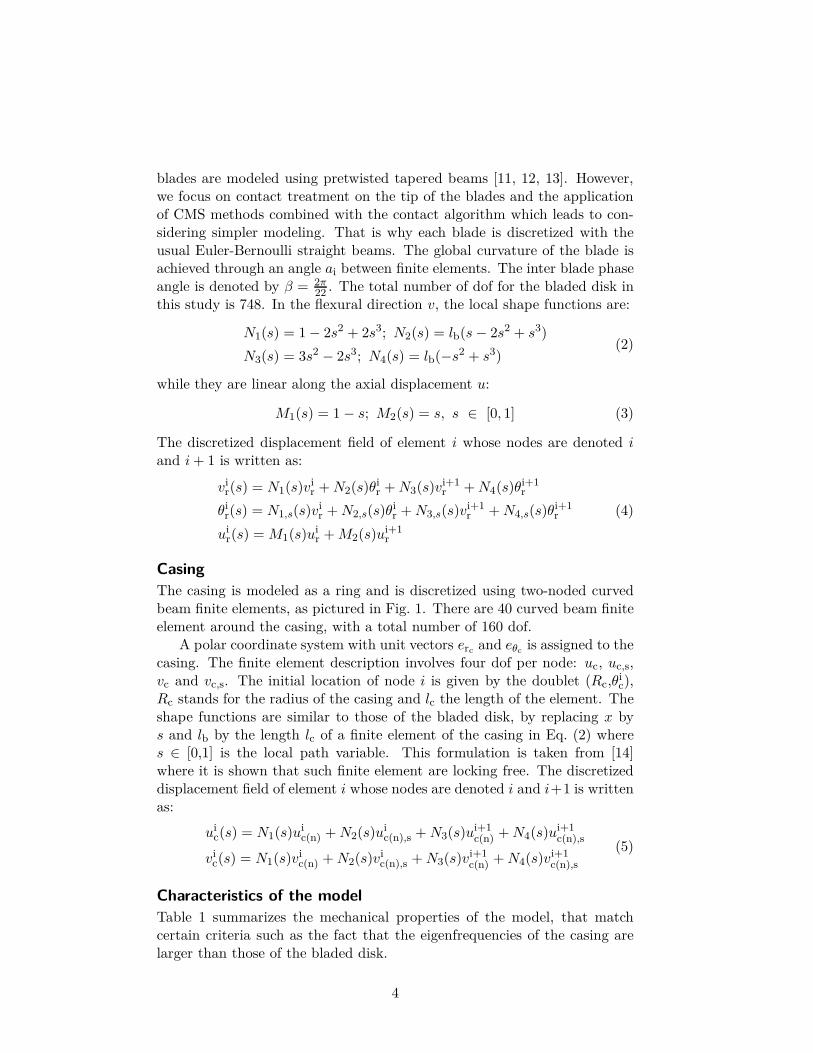
blades are modeled using pretwisted tapered beams [11, 12, 13]. However,we focus on contact treatment on the tip of the blades and the applicationof CMS methods combined with the contact algorithm which leads to con-sidering simpler modeling. That is why each blade is discretized with theusual Euler-Bernoulli straight beams. The global curvature of the blade isachieved through an angle ai between finite elements. The inter blade phaseangle is denoted by β = 2π
22 . The total number of dof for the bladed disk inthis study is 748. In the flexural direction v, the local shape functions are:
N1(s) = 1 − 2s2 + 2s3; N2(s) = lb(s − 2s2 + s3)
N3(s) = 3s2 − 2s3; N4(s) = lb(−s2 + s3)(2)
while they are linear along the axial displacement u:
M1(s) = 1 − s; M2(s) = s, s ∈ [0, 1] (3)
The discretized displacement field of element i whose nodes are denoted i
and i + 1 is written as:
vir(s) = N1(s)vi
r + N2(s)θir + N3(s)vi+1
r + N4(s)θi+1r
θir(s) = N1,s(s)vi
r + N2,s(s)θir + N3,s(s)vi+1
r + N4,s(s)θi+1r
uir(s) = M1(s)ui
r + M2(s)ui+1r
(4)
Casing
The casing is modeled as a ring and is discretized using two-noded curvedbeam finite elements, as pictured in Fig. 1. There are 40 curved beam finiteelement around the casing, with a total number of 160 dof.
A polar coordinate system with unit vectors ercand eθc
is assigned to thecasing. The finite element description involves four dof per node: uc, uc,s,vc and vc,s. The initial location of node i is given by the doublet (Rc,θi
c),Rc stands for the radius of the casing and lc the length of the element. Theshape functions are similar to those of the bladed disk, by replacing x bys and lb by the length lc of a finite element of the casing in Eq. (2) wheres ∈ [0,1] is the local path variable. This formulation is taken from [14]where it is shown that such finite element are locking free. The discretizeddisplacement field of element i whose nodes are denoted i and i+1 is writtenas:
uic(s) = N1(s)ui
c(n) + N2(s)uic(n),s + N3(s)ui+1
c(n) + N4(s)ui+1c(n),s
vic(s) = N1(s)vi
c(n) + N2(s)vic(n),s + N3(s)vi+1
c(n) + N4(s)vi+1c(n),s
(5)
Characteristics of the model
Table 1 summarizes the mechanical properties of the model, that matchcertain criteria such as the fact that the eigenfrequencies of the casing arelarger than those of the bladed disk.
4
Casing Bladed disk
Y.Modulus Ec = 2.8 · 103 Eb = 8.3 · 106
mass ρc = 2800 ρb = 7800thickness hc = 5 hb = 5width wc = 50 wb = 50radius Rc = 250.5 Rb = 250d.o.f nc = 160 nb = 748modal damping ξc = 0.03 ξb = 0.005number of blades N = 22
Table 1 – Characteristics of the model
3 Solution method
Time integration
The numerical methods are introduced in this section and described in thegeneral framework of the finite element methods. This part is devoted tothe computation of the reference solution. The general problem to be solvedmay be written as:
Mq + Dq + Kq = F
q(t = t0) = q0
q(t = t0) = q0
(6)
The contact conditions, referred to as the Kuhn-Tucker optimality condi-tions take the form:
∀x ∈ Γmc , tN ≥ 0, g ≥ 0, tNg = 0 (7)
where Γmc is the master surface (bladed disk) and tN stands for the contact
pressure, assumed positive, acting on the slave surface Γsc (casing). This
problem is solved using the explicit central differences scheme together withthe forward increment Lagrangian method [15, 16] and more details aboutthe algorithm used in this work may be found in [2].
Component mode synthesis
In most industrial applications, very large finite element models lead to cum-bersome computation times. One way to reduce these computation timesrelies in the use of component mode synthesis procedures [10]. Many studiesof these CMS methods have been carried out by coupling them to substruc-turing approaches [5]. Only the modal reduction aspect is considered here:CB method is applied on the bladed disk and on the casing considering eachof them as on substructure. The interface dof are related to each other in astrongly nonlinear fashion through unilateral contact and friction conditions.
CB and CCM methods first require the distinction of the dof of thestructure within two groups: the internal dof and the boundary dof. In
5
general the definition of these groups is closely related to the loadings appliedon the structures. In this study the boundary is supposed to contain allthe dof that might be supporting any contact force during the interaction,meaning the two dof u and v at the tip of each blade1 for the bladed diskand the u and v dof for each node of the casing.
Application
A reorganization of Eq. (6) is necessary, separating the dof in two groups:the internal dof (qI) and the interface (qB) yielding:[
MII MBI
MIB MBB
](
qI
qB
)
+
[
DII DBI
DIB DBB
](
qI
qB
)
+
[
KII KBI
KIB KBB
](
qI
qB
)
=
(
FI
FB
)
(8)Applying a CMS method consists in finding a reduction basis which dimen-sion is smaller than the number of dof of the structure reduced. This basisis represented through a rectangular matrix Φ. This matrix is defined bythe choice of the CMS technique.
Craig-Bampton method
The reduction basis of the CB method is composed of the following modes [6,10]:
1. fixed interface modes: Φfix
2. constraint modes: Φcons
The reduction matrix of the Craig Bampton method ΦCB is:
ΦCB = [ΦfixΦcons] (9)
The number of fixed-interface modes η kept in the reduction basis is theparameter of reduction:
(
qI
qB
)
= ΦCB
(
uη
qB
)
(10)
The projection of the equations of motion in the reduced space consists inthe following operations2:
K = ΦTCB
KΦCB and M = ΦTCB
MΦCB (11)
1Rotational θ on the tip of the blades is also considered as part of the boundary in thecase of the CCM method in order to enrich the space of the attachment modes. This doesnot modify contact treatment.
2Damping matrix D is usually computed directly from reduced stiffness and massmatrices K and M
6
Consequently, the dynamic equation in the reduced-order space becomes:[
Mηη MBη
MηB MBB
](
uη
qB
)
+
[
Dηη DBη
DηB DBB
](
uη
qB
)
+
[
Kηη KBη
KηB KBB
](
uη
qB
)
=
(
Fη
FB
)
(12)
Craig-Chang-Martinez method
This method is an enriched Craig-Martinez method [8, 17]. The reductionbasis is composed of the following modes [18, 10]:
1. free vibration modes
2. attachment modes
From a theoretical point of view, there is no restriction in the choice of thesemodes. From Eq. (6), the projection of the displacements q onto the modalcoordinates leads to:
q = Φ1u1 + Φ2u2 (13)
where Φ1 represents the free vibration modes kept in the reduction basisand Φ2 the modes that will be discarded for the reduction (high frequencymodes).
Considering the following approximation:
∀ ω22 ∈ diag(Ω2), ω2
≪ ω22 ⇒ Ω2u2 = ΦT
2 F (14)
and using the notation R = K−1 − Φ1Ω−11 ΦT
1 , the projection introduced inEq. (13) can be written as:
q = Φ1u1 + RF (15)
With Eq. (8), q = (qB, qI)T
(
qB
qI
)
=
[
Φ1B
Φ1I
]
u1 +
[
RB
RI
]
F (16)
This projection leads to the final equation:(
qB
qI
)
=
[
IBf 0
RIR−1B
Φ1i − RIR−1B
Φ1B
]
︸ ︷︷ ︸
PCM
(
qB
u1
)
(17)
where PCM is defined as the reduction matrix for the Craig-Martinez method.An alternative formulation of the Craig-Martinez method consists in addingattachment modes to the matrix Φ1 in Eq. (15). This enrichment leads tothe CCM method which is used in this paper.
7
4 Results
Note: displacements and time have been normalized and no unit is providedin the sequel.
Convergence analysis
beam i
beam i + 1
y0
xj-1yj-1
x0
xjyj
blade j + 1
blade j
blade j − 1
φ
lbx
Casing
Curved beamfinite element
ai
Figure 1 – Two-dimensional model used in the study
The interface of the bladed disk contains 44 dof where contact constraintsare treated, namely u and v at the tip of each blade. The casing is notreduced since its contact is managed on every node of the structure. Theinitial clearance between the tip of the blades and the casing is 1 mm.The rotational velocity of the bladed disk is constant for each simulation.Modal damping is applied for both structures. At time t = 0, an externalloading is applied on the casing. The deformation of the casing under thisloading depends on the nd parameter: number of nodal diameters of the twofree vibration modes on which the kinematic of the casing is reduced. Theloading is applied over t = 2 · 10−4 s.
With similar conditions, three specific interaction motions were detectedin [2] where models were projected in the modal space along two nd-nodaldiameter vibration modes subsequently implying strong kinematic restric-tions.
In total, three kinds of motions were observed in [2], namely damped,sustained and divergent motions respectively pictured in Figs. 2(a), 2(b)and 2(c). Among the different sustained motions observed, a specific kindinvolving locking was detected: a few blades come in permanent contactwith the casing, as illustrated in Fig. 2(c), and push a forward rotatingmode.
8
Beside of these three motions, relations have been established betweenthe number of blades and the kind of modal interaction detected. Precisely,it has been noticed that the interaction depends on the divisibility of thenumber of blades N by the number of diameters nd of the load exerted onthe casing. A 3-nodal diameter load on the casing might lead to lockedsustained motions with a 30 blades bladed disk while it could only lead tounlocked sustained motions with a 29 blades bladed disk. These resultsmatch geometrical observations: a stable interaction configuration can onlyoccur if the geometry of the deformed casing and bladed disk are compatible.It was also noticed that when the geometry allows for the system to beperfectly symmetric in terms of N and nd, the contact points will remain atthe same blade tips for all times.
All these considerations are explored in more details with new models inthe sequel.
Time convergence
The time step of the explicit central differences scheme is h = 2.5 · 10−7 s.This value has been obtained by considering both a convergence study fordamped and locked motions, respectively depicted in Figs. 3(a) and 3(b),and the following condition which is classical in linear analysis:
h <2
ωmax= 8.49 · 10−7 s (18)
Both Figs. 3(a) and 3(b) show blade tip/casing distance for a single bladeand different time steps. While convergence is easily observed as soon ash < 10−5 s in Fig. 3(a), it can be seen that the motion detected in Fig. 3(b)requires a smaller time step and convergence is only reached when h <
5 · 10−7 s: this shows that linear condition (18) is not restrictive enough fornon-linear systems.
Convergence regarding to the reduction basis
The convergence of reduced-order models constructed with CB and CCMtechniques is shown for each of the three interaction motions pictured inFigs. 2(a), 2(b) and 2(c). While damped and locked motions are obtainedwith nd = 2, the sustained motion is obtained for nd = 3 only. Indeed,it has been notice [2] that locked motions may only be observed when thevalue of nd divides the number of blades. If not, sustained motion is morelikely to occur.
Craig-Bampton method
The convergence of the results for CB reduced-order models when η increasesis shown in Figs. 4(a), 4(b) and 4(c)3. One may clearly observe the high
3Results are shown as blade tip/casing distances for a blade randomly chosen. Resultsin terms of convergence are similar for other blades.
sensitivity of the results to the reduction basis in the case of locked andsustained motions in Figs. 4(b) and 4(c). The quality of the approximationof the blade tip displacements directly depends on the modal reduction basis.As a consequence, the reduction basis will influence the blades that will lock
10
0 0.3 0.6 0.9 1.2 1.50
0.25
0.5
0.75
time
bla
de
tip
/ca
sin
gd
ista
nce
(a) Damped motion, blade 9, nd = 3
0 0.5 1 1.5 2 2.50
0.5
1
1.5
time
bla
de
tip
/ca
sin
gd
ista
nce
(b) Locked motion, blade 2, nd = 2
Figure 3 – Blade tip/casing distance for two blades and two differentsimulations when time steps varies: h = 10−5 s ( ), h = 5 · 10−6 s( ), h = 10−6 s ( ), h = 5 · 10−7 s ( ), h = 2.5 · 10−7 s ( ) andh = 10−7 s ( )
on the casing. If the locking blades change, then all the displacements onthe bladed disk are modified which causes the variation of vibration levelobserved in Figs. 4(b) and 4(c).
Craig-Chang-Martinez method
Results of the convergence of the reduced-order-models are shown for damped,locked and sustained motions in Fig. 5(a), 5(b) and 5(c), respectively. Dif-ferences observed in terms of convergence with the CB method are not sig-nificant since convergence seems faster for locked motions and slower fordamped motions. However, as previously observed for the CB method, avery high number of modes is required to ensure convergence in terms ofblade tip displacements.
Results obtained for the two CMS methods show that the convergencetoward the finite element solution is fairly slow. For the CB method, it
11
time0 1
0
0.25
0.5
0.75
1
1.25
bla
de
tip
/ca
sin
gd
ista
nce
(a) Damped motion, blade 10
0 0.4 0.8 1.2 1.6 2
time
0
0.5
1
1.5
bla
de
tip
/ca
sin
gd
ista
nce
(b) Locked motion, blade 9
0 0.4 0.8 1.2 1.6 2
time
0
0.5
1
1.5
bla
de
tip
/ca
sin
gd
ista
nce
(c) Sustained motion, blade 2
Figure 4 – Convergence of the results obtained with CB method for eachkind of interaction η = 0 ( ); η = 44 ( ); η = 88 ( ); η = 220 ( );ufe(t) ( )
is noticeable that for low η (η = 0 and η = 44), the results are stronglydifferent from the finite element solution. In comparison, for similar φ, theCCM reduced-order models lead to better results. However, while η and φ
12
time0 1
0
0.25
0.5
0.75
1
1.25
bla
de
tip
/ca
sin
gd
ista
nce
(a) Damped motion, blade 10
0 0.4 0.8 1.2 1.6 2
time
0
0.5
1
1.5
bla
de
tip
/ca
sin
gd
ista
nce
(b) Locked motion, blade 9
0 0.4 0.8 1.2 1.6 2
time
0
0.5
1
1.5
bla
de
tip
/ca
sin
gd
ista
nce
(c) Sustained motion, blade 2
Figure 5 – Convergence of the results obtained with CCM method foreach kind of interaction φ = 0 ( ); φ = 44 ( ); φ = 88 ( );φ = 220 ( ); ufe(t) ( )
increase, convergence is observed more rapidly for the CB method than forthe CCM method as it can be seen in Fig. 6 for a sustained motion.
For both methods, η = 88 and φ = 88 seem to be the minimum threshold
13
0 00.4 0.40.8 0.81.2 1.21.6 1.62 2
time time
0
0.5
1
1.5
CB CCM
bla
de
tip
/ca
sin
gd
ista
nce
Figure 6 – Comparison of CB (CB) and CCM results ( ) to the finiteelement solution ( ) with η = 220 and φ = 220
to get good results at the exception of the locked motion with CB reduced-order models η = 88 is a lower bound. Comparatively to the total numberof dof of the bladed disk, these values of η and φ may appear very high(≃ 12%). Such a ratio might not be acceptable in the case of complexindustrial 3D models containing several millions of dof. Consequently, it isof interest to ensure that displacement convergence requires higher η and φ
than motion convergence in terms of type of detected motions.
Motion convergence
In order to assess the convergence in terms of motions, reduced-order modelsare built with η = 44, η = 88, φ = 44 and φ = 88. Several simulations areperformed while increasing the rotational velocity Ω and friction coefficientµ. Resulting maps, illustrated in Figs. 7 and 8 allow for an estimation ofthe influence of detected motions to parameters η and φ for nd = 2. Areasin black ( ) represent divergent motions, areas in grey ( ) representlocked motions and white areas show damped motions. The comparisonsdisplayed in Figs. 7 and 8 suggest that motion convergence is easily reachedwith the CB method. For both CB and CCM reduced-order models, it canbe observed that a smaller modal description (η = 44 and φ = 44) tends tofavor damped motions. In the specific case of the CB reduced-order model,the value of η does not disturb the transition between the locked motionand the divergent motion areas. However, for CCM reduced-order models,this transition is modified and the locked motion area is less homogeneousfor φ = 44.
The results for the CCM reduced-order models put into perspective theresults pictured in Figs. 5(a), 5(b) and 5(c) emphasizing the importance ofa large φ to reach motion convergence. Only a few differences are distin-guishable between the maps for η = φ = 88, particularly for low rotatingspeeds and low friction coefficients. The fact that these two maps match –and because they are obtained with two different CMS methods using dif-
14
0
0.5
1
1.5
2
2.5
3
3.5
4Ω
0.20.2 0.40.4 0.60.6 0.80.8 11
µµ
Ωc
η = 44 η = 88
Figure 7 – Motions detected with CB method for η = 44 and η = 88function of µ and Ω
0
0.5
1
1.5
2
2.5
3
3.5
4
Ω
0.20.2 0.40.4 0.60.6 0.80.8 11
µµ
Ωc
φ = 44 φ = 88
Figure 8 – Motions detected with CCM method for φ = 44 and φ = 88function of µ and Ω
ferent reduction basis – justifies that results converged in terms of motions.A similar map with finite element models cannot be obtained since it wouldlead to prohibitive computation times.
15
5 Conclusions
The combination of component mode synthesis methods with a contact algo-rithm based on the Lagrange multiplier technique was introduced in [10, 19].Our study shows that the use of a CMS method minimizes computationtimes depending the type of convergence sought. For planar finite elementmodels, it was shown that a reasonable number of modes in the modal re-duction basis – such as η = 44 in CB method – are necessary to preciselydetermine the different motions. However, in order to get a good accuracyin terms of displacements, the size of the modal reduction basis has to beincreased due to the high numerical sensitivity of the locking phenomenon.In that case, CCM gives better results with a smaller reduction basis.
Considering these results, work is in progress to evaluate the influenceof the kinematic restrictions used in our study on the casing and their rolein modal interaction detection.
Acknowledgment
Thanks go to Snecma for its technical and financial support. This work takesplace in the framework of the MAIA mechanical research and technologyprogram sponsored by CNRS, ONERA and SAFRAN Group.
References
[1] Legrand, M., 2005. “Modèles de prediction de l’interaction rotor/statordans un moteur d’avion”. Phd thesis, École Centrale de Nantes, Nantes,France.
[2] Legrand, M., Pierre, C., Cartraud, P., and Lombard, J. P., 2009. “Two-dimensional modeling of an aircraft engine structural bladed disk-casingmodal interaction”. Journal of Sound and Vibration, 319(1-2), pp. 366–391.
[3] Schmiechen, P., 1997. “Travelling wave speed coincidence”. Phd thesis,Imperial College of London.
[4] Berthillier, M., and Mascarell, J. P. Vibration des roues aubagées :étude de l’interaction rotor-stator, rapport interne ylec n dr/152/91.Tech. rep., Snecma.
[5] Rixen, D. J., 2004. “A dual craig-bampton method for dynamic sub-structuring”. Journal of Computational and applied mathematics, 168,pp. 383–391.
[6] Craig, R. R. J., and Bampton, M. C. C., 1968. “Coupling of substruc-tures for dynamic analyses”. AIAA Journal, 6(7), pp. 1314–1319.
16
[7] Craig, R. R. J., 1977. “Methods of component mode synthesis.”. Shockand Vibration Digest Journal, 9, pp. 3–10.
[8] Tran, D. M., 2000. “Component mode synthesis methods using interfacemodes. application to structures with cyclic symmetry”. Computers &Structures, 79, pp. 209–222.
[9] Martinez, D. R., Carne, T. G., Gregory, D. L., and Miller, A. K., 1984.“Combined experimental/analytical modeling using component modesynthesis”. Computers & Structures, 78, pp. 583–590.
[10] Batailly, A., Legrand, M., Cartraud, P., Pierre, C., and Lombard, J. P.“Study of component mode synthesis methods in a rotor-stator inter-action case”. Proceedings of the ASME 2007 International Design En-gineering Technical Conferences & Computers and Information in En-gineering Conference: IDETC07, September 2007, Las Vegas, Nevada.
[11] Swaminathan, M., and Rao, J. S., 1977. “Vibrations of rotating,pretwisted and tapered blades”. Mechanism and Machine Theory, 12,pp. 331–337.
[12] Kuang, J. H., and Huang, B. W., 1999. “Mode localization of a crackedblade disk”. Journal of Engineering for Gas Turbines and Power, 121,pp. 335–341.
[13] Young, T. H., 1991. “Dynamic response of a pretwisted, tapered beamwith non-constant rotating speed”. Journal of Sound and vibration,150, pp. 435–446.
[14] Raveendranath, P., Singh, G., and Pradhan, B., 2000. “Free vibrationof arches using beam element based on a coupled polynomial displace-ment field”. Journal of Computational and applied mathematics, 168,pp. 383–391.
[15] Simo, J. C., and Laursen, T. A., 1992. “An augmented lagrangian treat-ment of contact problems involving friction”. Computers & Structures,42(1), pp. 97–116.
[16] Carpenter, N., Taylor, R., and Katona, M., 1991. “Lagrange constraintsfor transcient finite element surface contact”. International Journal forNumerical Methods in Engineering, 32, pp. 103–128.
[17] Tournour, M. A., Atalla, N., Chiello, O., and Sgard, F., 2001. “Valida-tion, performance, convergence and application of free interface com-ponent mode synthesis”. Computers & Structures, 79, pp. 1861–1876.
[18] Craig, R. R. J., and Chang, C. J. “On the use of attachment modes insubstructure coupling for dynamic analysis”. presented at AIAA/ASME
17
18th Structures, Structural Dynamics and Materials Conference, SanDiego, California.
[19] Batailly, A., 2008. “Simulation de l’interaction rotor/stator pour desturbomachines aéronautiques en configuration non-accidentelle”. Phdthesis, École Centrale de Nantes, Nantes, France.