Page 1
EVALUATION OF CONTAMINANT CONTAINMENT
AT REGINA LANDFILL
A Thesis
Submitted to the Faculty of Graduate Studies and Research
In Partial Fulfillment of the Requirements
For the Degree of
Master of Applied Science
in
Environmental Systems Engineering
University of Regina
By
Joshua Frederick
Regina, Saskatchewan
March 2014
Copyright 2014: Frederick, Joshua
Page 2
UNIVERSITY OF REGINA
FACULTY OF GRADUATE STUDIES AND RESEARCH
SUPERVISORY AND EXAMINING COMMITTEE
Joshua Frederick, candidate for the degree of Master of Applied Science in Environmental Systems Engineering, has presented a thesis titled, Evaluation of Contaminant Containment at Regina Landfill, in an oral examination held on October 9, 2013. The following committee members have found the thesis acceptable in form and content, and that the candidate demonstrated satisfactory knowledge of the subject material. External Examiner: Mr. Sean Bayer, KGS Group
Supervisor: Dr. Yee-Chung Jin, Environmental Systems Engineering
Committee Member: Dr. Tsun Wai Kelvin Ng, Environmental Systems Engineering
Committee Member: Dr. Stephanie Young, Environmental Systems Engineering
Chair of Defense: Dr. Denise Stilling, Industrial Systems Engineering
Page 3
i
ABSTRACT
Landfill and waste containment facilities are routinely constructed on natural or
engineered low permeability barriers placed above or within th vadose zone to prevent
contaminant migration into the groundwater system. Numerical estimates of design lives
for assessment of barrier system performance are generally acceptable under numerous
landfill regulations. Predictive models work under the general assumption that
constructed systems will retain their structural integrity over the design life of the landfill
and act as leak proof systems. Contrary to the above assumption, barrier performance,
whether natural or engineered, at countless landfills and waste disposal sites across North
America suggests that these liners tend to act as leak-resistant, and not leak-proof,
systems. Across Canada, the designs of these barrier systems at various landfill sites are
typically governed by prescriptive engineering design standards as opposed to
performance or risk-based standards set by the regulatory agency having jurisdiction over
the landfill.
This study investigates the contaminant containment potential of a composite
landfill liner system in conjunction with the naturally occurring glacioacustrine clay
barrier at the Regina landfill expansion site. Transit time was calculated for the different
landfill design types as prescribed under the Saskatchewan Environment Code (SEC) and
compared to simulations using two commercially-available, one-dimensional modeling
software packages. VZCOMML©
a one-dimensional, steady-state, equilibrium
partitioning vadose zone model that uses a multi-layered soil column was used to
Page 4
ii
simulate advective flows; and CHEMFLUX, a one-dimensional model to simulate
diffusion.
The results suggest that inherent low permeability property of the native barrier
underlying the landfill is adequate to prevent potential contamination of groundwater
over the “contaminating life span” (Rowe, 2005) of the landfill expansion area. However,
the natural barrier has finite hydraulic conductivity and ultimately, over long periods of
time, breakthrough will occur due to diffusion. The literature review and modeling
investigation indicate that more attention should be directed towards active contaminant
removal, treatment, and disposal as opposed to pure contaminant containment at landfill
sites over their design life. There seems to be overemphasis on dry tomb designs focused
on contaminant containment, liner effectiveness, and review of hydrogeological aspects
as key landfill performance indicators. With current trends in innovation and evolution in
landfill technologies, landfills should be viewed as solid waste processing facilities and
not waste burial sites. This study hypothesises that a systems approach to design and
performance evaluation centered on total lifetime contaminant mass management would
be more ideal for the Regina Landfill site.
Page 5
iii
ACKNOWLEDGEMENTS
I would like to specially thank my supervisor Dr. Jin and co-supervisor Dr.
Viraraghavan for this tremendous opportunity and their valuable guidance on this project.
I would also like to thank my family—Sandhya, Rohan and Tanishqa—for their
continued support throughout the program. I should not forget to thank my brother Adam
for his encouragement.
Page 6
iv
TABLE OF CONTENTS
ABSTRACT ..................................................................................................................................... i
ACKNOWLEDGEMENTS ......................................................................................................... iii
TABLE OF CONTENTS ................................................................................................ iv
NOMENCLATURE ......................................................................................................... vi
LIST OF FIGURES ........................................................................................................ vii
LIST OF TABLES ........................................................................................................................ ix
1.0 INTRODUCTION ................................................................................................................... 1
1.1 OBJECTIVES OF THE STUDY ................................................................................................. 2
2.0 LITERATURE REVIEW ....................................................................................................... 4
2.1 GROUNDWATER CONTAMINATION ..................................................................................... 4
2.2 LEACHATE CHARACTERISTICS ............................................................................................ 8
2.3 CONTAMINANT TRANSPORT THROUGH THE VADOSE ZONE ............................................ 13
2.4 HYDROGEOLOGICAL CONDITIONS .................................................................................... 15
2.5 CONTAMINANT ATTENUATION PHENOMENON ................................................................. 18
2.6 LANDFILL LINER DESIGN AND THE REGULATORY SYSTEM ............................................. 20
2.7 NUMERICAL MODELLING OF LEACHATE MIGRATION ....................................................... 31
3.0 MODELLING OF CONTAMINAMT CONTAINMANT POTENTIAL ........................ 33
3.1 LOCAL SUBSURFACE GEOLOGY ........................................................................................ 33
3.2 EXTENT OF AQUIFERS AND GROUNDWATER QUALITY IMPACTS ..................................... 35
3.3 MODELLING PROGRAM .................................................................................................... 38
3.4 EVALUATION OF TRANSIT TIME ...................................................................................... 42
3.5 VZCOMML MODEL ........................................................................................................ 45
Page 7
v
3.6 MODELLING ASSUMPTIONS ............................................................................................. 47
3.7 PREDICTING CHLORIDE MIGRATION……………………………………………………………………………50
3.8 CHEMFLUX MODEL ....................................................................................................... 50
4.0 RESULTS AND DISCUSSSION .......................................................................................... 54
4.2 GENERAL DISCUSSION ..................................................................................................... 68
4.3 A SYSTEMS ENGINEERING APPROACH TO DESIGNING LANDFILL LINERS ....................... 73
5.0 CONCLUSIONS AND RECOMMENDATIONS ............................................................... 75
5.1 CONCLUSIONS .................................................................................................................. 75
5.2 RECOMMENDATIONS ........................................................................................................ 76
REFERENCES............................................................................................................................. 77
Page 8
vi
NOMENCLATURE
BOD biochemical oxygen demand
BTEX benzene, toluene, ethylbenzene, and xylenes
COD chemical oxygen demand
ha hectares
HDPE high density polyethylene
K hydraulic conductivity
MCL maximum contaminant level
MSW municipal solid waste
n total porosity
NAPL non-aqueous phase liquids
pH soil pH
R retardation factor
TDS total dissolved solids
TOC total organic carbon
yrs years
Page 9
vii
LIST OF FIGURES
Figure 2.1 Typical contaminant migration into the groundwater system ........................................ 7
Figure 2.2 Hysteresis of a soil moisture characteristic curve …………………………….…......26
Figure 2.3 Typical approaches to landfill classification ................................................................ 21
Figure 2.4 Typical cross-section of liner system-nova scotia landfill guidelines .......................... 25
Figure 2.5 Landfill barriers systems across the world………………………................……...…39
Figure 3.1 Schematic geological and hydrological setting of the Regina area……...….………...43
Figure 3.2 City of Regina landfill site plan including expansion area ........................................... 36
Figure 3.3 Regional aquifer system beneath landfill site ............................................................... 37
Figure 3.4 The relationship of dimensionless parameters & concentration……………..….…….53
Figure 3.5 VZCOMML vadose zone contaminant migration model ............................................. 48
Figure 3.6 Concept diagram of the three models used in the study…...………….…… ………..61 Figure 3.7 Chemflux model mesh used to simulate 1-d transport………....……… …….……...52
Figure 4.1 Chemflux con. vs depth results without geomembrane- 10 yrs .................................... 59
Figure 4.2 Chemflux con. vs depth results without geomembrane- 25 yrs .................................... 59
Figure 4.3 Chemflux con. vs depth results without geomembrane - 45 yrs ................................... 69
Figure 4.4 Chemflux con. vs depth results without geomembrane - 65 yrs ................................... 69
Figure 4.5 Chemflux con. vs depth results without geomembrane- 100 yrs .................................. 61
Figure 4.6 Chemflux con. vs depth results without geomembrane- 200 yrs .................................. 61
Figure 4.7 Chemflux con. vs depth results with geomembrane- 10 yrs ......................................... 62
Figure 4.8 Chemflux con. vs depth results with geomembrane- 25 yrs ......................................... 62
Figure 4.9 Chemflux con. vs depth results with geomembrane- 45 yrs ......................................... 63
Figure 4.10 Chemflux con. vs depth results with geomembrane- 100 yrs ..................................... 63
Figure 4.11 Chemflux con. vs depth results with/without geomembrane- 100 yrs ....................... 64
Figure 4.12 Chemflux con. vs depth results leaky geomembrane- 10 yrs ..................................... 65
Figure 4.13 Chemflux con. vs depth results leaky geomembrane- 45 yrs ..................................... 65
Page 10
viii
Figure 4.14 Chemflux con. vs depth results with leaky geomembrane- 65 yrs ............................. 66
Figure 4.15 Chemflux con vs depth results with leaky geomembrane-100 yrs ……….………...67
Figure 4.16 Chemflux acumesh results without geomembrane……………………..…………...76 Figure 4.17 Schematic showing modified double composite liner system ................... …….….72
Page 11
ix
LIST OF TABLES
Table 2.1 Typical chemical concentrations in leachate from MSW landfills ..................... 9
Table 2.2 Physicochemical characteristics of potential sub-surface contaminants ......... 11
Table 3.1 Description of landfill design types as per SEC .............................................. 49
Table 3.2 Selection of landfill design type ...................................................................... 41
Table. 3.3 VZCOMML 1-D Model Inputs ...................................................................... 53
Table 3.4 Material porosity and Saturated Hydraulic Conductivity ................................ 53
Table 4.1 VZCOMML Results on SEC Design types ..................................................... 56
Table 4.2 Transit time evaluation .................................................................................... 57
Table 4.3 Transit Time Evaluation – Active Leachate Removal/Treatment ................... 58
Table 4.4 Regina Landfill Phase 2 Expansion costs ........................................................ 71
Page 12
1
INTRODUCTION
Solid waste disposal continues to be a major method of waste disposal in North
America and the world over. In 2001, it was estimated that over 229 million tons of waste
was disposed of annually in the United States (US EPA, 2003). The Regina Fleet Street
Landfill, the subject site of this study, on average receives about 500,000 tonnes of
municipal solid waste each year. Of the waste received, 20% of the material is recovered
and recycled by the City, 40% is soil material used for daily cover, and the remaining
40% of the total waste is garbage (City of Regina, 2009).
The original landfill site was established in 1961 over 97 ha and reached its
maximum capacity in 2011. In 2010, the City of Regina commenced a 3-phase
progressive expansion plan over 59.2 ha adjacent to the existing site to provide
additional capacity of approximately 25 million cubic meters (City of Regina, 2009) with
an estimated life expectancy of 80 yrs. An important point to note is that the current
landfill and expansion area are both located within the City of Regina’s aquifer protection
zone and falls under a medium sensitivity area classification.
Waste disposal facilities are commonly known to pose significant risk to
groundwater systems because of leachate generation caused by water percolating through
the waste mass and potentially into the aquifer. Leaching from landfills has been reported
to increase concentrations of chlorides, sulphates, nitrates, iron, and other inorganic and
organic substances in the groundwater system. Cases of groundwater contamination
often go undiscovered until or after a drinking water source is contaminated (Veronica
and Kelly, 1987).
Historically, in order to prevent leachate from entering groundwater systems,
Page 13
2
numerous landfills across the interior plains of North America were established over
naturally occurring glacial clayey till and cretaceous clay deposits with their
characteristic low hydraulic conductivities (Rowe et al, 1995). The Regina Fleet Street
landfill is an archetype located in a semi-arid zone, with low annual precipitation and
sited over an expanse of un-weathered surficial glacioacustrine clay and fractured till.
1.2 Objectives of the study
Clayey deposits beneath landfill sites are commonly viewed as effective buffers
against leachate migration. The attenuating ability of these naturally occurring earthen
barriers may have been overestimated traditionally based on simple permeability
assumptions. Computer models are commonly used to predict long-term performance of
waste containment systems and modeling data suggests that modern landfill containment
barriers perform reasonably well. However, long-term performance models typically rely
on extrapolations of data using numerous assumptions and may hold significant
ambiguity within the models.
The study investigates the effectives of the composite liner system proposed
under the new Saskatchewan Environment Code regulatory system and mean travel time
for chloride to reach the base of vadose zone and the maximum groundwater
concentration at a receptor location along the edge of the waste facility is estimated. A
‘what-if’ analysis also examines different landfill design types proposed under the new
Code.
It should be noted that this study has consciously taken a broad environmental
engineering approach to assess the problem and has focused on the application of the
Page 14
3
new SEC in the hope of better understanding the evolution of environmental controls
at landfill sites and their long term implications.
Page 15
4
2 LITERATURE REVIEW
2.1 Groundwater Contamination Groundwater is recognised as a valuable natural resource used primarily for
drinking and irrigation. It is estimated that about 293 million cubic meters of ground
water are withdrawn daily in the United States and in 1995, the United States Geological
Survey (USGS) reported that ground water supplied 46% of the nation’s overall
population and 99% of the rural population with drinking water (USEPA, 2000). In
Canada, 8.9 million people, approximately 30.3% of the population, rely on groundwater
for domestic use (Environment Canada, 1996).
Naturally-occurring processes and various human activities may reduce the
quality of subsurface waters. Groundwater contamination can have significant negative
impact on humans and ecosystems. Solid waste disposal on land continues to be a major
source of groundwater contamination. Infiltration through municipal and industrial refuse
disposed of in landfill sites over a period of time generates leachate which contains
various metals and organic and inorganic chemical species. According to Environment
Canada, landfills pose significant risk to groundwater across the country and major
drinking water sources in groundwater-dependant communities like Elmira, Ontario and
Abbotsford, British Columbia have been contaminated by poor waste disposal practice
(Environment Canada, 2001). In the United Kingdom from a study conducted by Harris
(1997) in a densely populated area, it was reported that landfill sites were numerically the
most significant category of land use giving rise to groundwater pollution. Harris also
reported that metallic compounds were the most commonly occurring contaminant and
the pollution by organic compounds outweighed problems by inorganics. The issue is
Page 16
5
serious in North America: for instance, a National Research Council report (2007) noted
that in the United States, there are approximately 4,000 landfills and about 7,800
contaminated sites requiring clean up.
Ground-water contamination is therefore a major concern because of its
potential impact on drinking water sources and may even cause permanent damage to
subsurface water quality. According to USEPA (1984), some of the contaminants from
landfills include organic solvents, heavy metals, inorganic chemicals, organic chemicals,
soil fumigants, pesticides, and pathogens.
Some of the naturally occurring causes of groundwater pollution were studied by
Desauliners et al. (1981) who reported that surficial soils may often be characterized by a
large concentration of total dissolved solids due to processes including sulphide
oxidation, cation exchange, and carbonate mineral dissolution. Sulphate increase in the
groundwater system has also been observed from gypsum dissolution when it is a
common construction material disposed off at landfill sites (Custodio, 1997).
Howard and Gerber (1997) conducted a contaminant source audit for a 700 km2
sub-region of the Greater Toronto Area and reported that the “impact potential” (i.e. the
volume of water that would be contaminated to the standard by the available mass)
exceeded 3 billion litres. BTEX and phenols, according to Howard and Gerber, represent
the most serious problem; they suggested that risks may be significantly alleviated by
biodegradation and volatilization. The other high-risk reported chemicals included
copper, lead and cyanide primarily from landfills; sodium and chloride from de-icing
chemicals; and nitrate from a combination of other sources. Drinking Water Standards
therefore serve as an important basis for appraising groundwater quality and assessing
Page 17
6
chemical threats.
In terms of transport and fate characteristics, leachates are known to
exhibit a wide range of behaviours. Contaminants in ground-water generally move in a
plume with relatively little mixing or dispersion. Concentrations tend to remain high.
These plumes of relatively concentrated contaminants move slowly through the aquifer
and can be typically present for many years (EPA, 1984). Groundwater contamination
often results in aquifers or parts of aquifers being damaged beyond repair (Freeze and
Cherry, 1979). Therefore, more emphasis should be directed towards developing
processes and design standards that control the migration of dissolved contaminants
through unsaturated soils that serve as containment barriers for aquifers beneath. Typical
contaminant migration into the groundwater system is depicted below in Fig 2.1.
Page 18
7
Figure 2.1. Typical contaminant migration into the groundwater system (Freeze and Cherry, 1979)
Page 19
8
2.2 Leachate Characteristics Leachate from a decomposing landfill contains a wide range of inorganic, organic
chemicals, and its composition and characteristics are complex. Typical chemical
constituents in leachate from MSW landfills are shown in Table 2.1. It is necessary to
understand various physical/chemical characteristics and temporal variations in leachate
chemistry before quantifying transport. Leachate quality is generally affected by
different processes of waste decomposition. Solid waste decomposition generally goes
through the phases of being initially aerobic, secondly anaerobic and finally
methanogenic. McBean et al. (1995) noted that leachate produced during the aerobic
decomposition process is typically characterized by high BOD values (>10,000 mg/l) and
high ratio of BOD to COD (>0.7) with a large proportion of soluble organic matter being
readily biodegradable. According to Qian et al., (2002), during the anaerobic
decomposition stage, leachate is reported to be chemically aggressive, acidic in nature
with pH levels between 5 to 6, and known to cause dissolution of other components of
the waste that result in high levels of iron, manganese, zinc, calcium, and magnesium in
the leachate. The last stage of methanogenisis produces leachate that has stabilized,
Page 20
9
Table 2.1. Typical chemical concentrations in leachate from MSW landfills (Lee et al., 1993)
Parameter "Typical" Concentration Range (All values in mg/L except as noted)
BOD 1,000 - 30,000 COD 1,000 - 50,000 TOC 700 - 10,000
Total volatile acids (as acetic acid) 70 - 28,000
Tota Kjeldahl Nitrogen (as N) 10 - 500
Nitrate (as N) 0.1 - 10 Ammonia (as N) 100 - 400
Total Phosphate (PO4) 0.5 - 50 Orthophospate (PO4) 1.0 - 60
Total alkalinity (as CaCO3) 500 - 10,000 Total hardness (as CaCO3) 500 - 10,000
Total solids 3,000 - 50,000 Total dissolved solids 1,000 - 20,000
Specific conductance (mhos/cm) 2,000 - 8,000
pH 5 - 7.5 Calcium 100 - 3,000
Magnesium 30 - 500 Sodium 200 - 1,500 Chloride 100 - 2,000 Sulphate 10 - 1,000
Chromium (total) 0.05 - 1 Cadmium 0.001 - 0.1
Copper 0.02 - 1 Lead 0.1 - 1
Nickel 0.1 - 1 Iron 10 - 1,000 Zinc 0.5 - 30
Page 21
10
(characterized by lower BOD values and low ratios of BOD to COD) and acetogenic and
methanogenic bacteria present are at dynamic equilibrium (McBean et al., 1995). Apart
from these general sequential processes that affect leachate characteristics, leachate
quality would vary from one landfill to another based on the kind of waste received, age
of the landfill, climatic conditions, site hydrogeology and other operating conditions such
as cell design, waste placement and type of cover material.
Landfill leachate can also introduce bacteria and viruses into the subsurface. The
fate and transport of bacteria and viruses in the subsurface is an important consideration
in the evaluation of the effects of landfills on human health and the environment. Virus
and bacterial survival/ transport in the subsurface is generally influenced by a large
number of biological, chemical, and physical processes. Typical physicochemical
characteristics of potential sub-surface contaminants as noted by Melinda (1997) are
outlined in Table 2.2.
Page 22
11
Table 2.2 Physicochemical characteristics of potential sub-surface contaminants (Melinda et al., 1997)
Pollutant Aqueous Solubility
Potential for NAPL Formation
Controlled by pH/Eh
Attenuated/ Sorbed
in Soil zone Persistent in Subsurface
Acceptable concentrations
in potable water Chloride High No No No Yes Low-moderate
Nitrate High No No Used by
plants
Yes where
aerobic Low moderate
Heavy metals Low No Yes Yes Yes Very low
Hydrocarbons Low Yes No Yes Varies Trace
Chlorinated
solvents Low Yes No Yes Yes Trace-very low
Pesticides Low No No Yes Varies Trace
Pathogens - No - Yes Varies None
Radionuclides Varies No Yes Yes Yes Trace
Page 23
12
The extent of impact on important aquifers depend on leachate characteristics
and final concentration at the point of dispersion. According to Melinda et al., (1997)
moderation of these impacts on groundwater systems can be expected as a result of
physical-chemical processes such as sorption onto natural organic materials or clays,
chemical precipitation, oxidation/reduction reactions, and biological degradation to risk-
free compounds.
Besides the detrimental impact leachates have on the groundwater system,
permeating contaminants have also been reported by Oweis and Khera (1998) to change
the engineering properties of clayey soils by: altering the soil structure, increase or
decrease in the diffuse double layer thickness, dissolution of soil components by strong
acids and bases, blockage of soil voids due to precipitation, and growth of micro-
organisms. Fernandez and Quigley (1991) permeated clay samples using municipal solid
waste leachates containing ethanol and dioxane and reported that leachate concentrations
in excess of 70% can cause damaging increases in hydraulic conductivity (K) of up to
1000-fold. As a counter example to the above case where the soil interaction with
concentrated organic leachates caused a significant increase in hydraulic conductivity,
Rowe et al., (2002) reported clogging mechanisms in a granulated medium permeated
with synthetic leachate and reported that there can be decrease in hydraulic conductivity
by up to seven orders of magnitude due to microbially induced clogging. Rowe et al.,
(2001) also performed permeability tests on a natural clayey till using different ionic
contaminant solutions (CaCl2, MgCl2, NaCl and acetic acid) and found the complex
permittivity to be considerably sensitive to concentration of ions in the pore fluid.
Page 24
13
In swelling soils similar to those found at the Regina Landfill site, interaction
between inorganic compounds and soils, such as sodium bentonite, were reported by
Oweis and Khera, (1998) to exhibit large changes in hydraulic conductivity with the
exchange of the absorbed cations. Changes in soil volume were also reported as organic
cations impacted the swelling capacity of smectite (Oweis and Khera, 1998). Yatkwong
and Dennis (1987) studied the effects of brine contamination on two fine grained soils,
Indian Head Till and Regina Clay, and observed that soils exhibited non-dispersive
behaviour after brine contamination with a noted decrease in hydraulic conductivity. The
diffusion coefficients reported were in the range of 10-6 to 10-7 cm2/sec and 4 X 10⁻⁶
cm2/sec for Regina Clay. Though the literature above suggests that leachates generally
attack clay liners, Shackelford (1989) has noted that only concentrated leachate
constituents are of serious concern and in most instances, landfill leachates may not
degrade clay liners. Based on the above, leachate characterization and developing an
understanding of relative impacts plays an important role in transport analysis. It is
interesting to note that majority of the studies reviewed tend to analyze leachates, their
effects and transport as individual chemical constituents and a “cocktail” approach is
largely avoided. This is likely due to various complexities that arise in dealing with
multiple chemical characteristics at one time.
2.3 Contaminant Transport through the Vadose Zone
Contaminant transport through the vadose or otherwise known as the unsaturated/
temporarily saturated zone is generally governed by transport and attenuation
mechanisms and these have been extensively studied over the last three decades (Freeze
Page 25
14
and Cherry, 1979; Gillham et al., 1984; Quigley and Rowe., 1986; Quigley et al., 1987;
Daniel and Shackelford, 1988; Rowe et al., 1997; El-Zein and Rowe, 2007; Rowe and
Hosney 2010; Rowe and Abdelatty, 2012). Understanding the fate and transport of
contaminants through these clayey barriers at the Regina Landfill is crucial in assessing
their contaminant containment potential. In keeping with Rowe who has extensively
researched the subject over many decades, the process for conducting quantitative
predictions of contaminant transport generally includes:
1) Identifying the primary transport mechanisms and contaminant sinks,
2) Formulation of a theoretical model to describes these mechanisms,
3) Determination of relevant parameters, and
4) Solving governing equations for the specific problem.
There are two basic transport mechanisms that effect movement of miscible and
immiscible pollutants through the vadose zone: advection and diffusion. Advection refers
to movement of soluble species along with the flow of subsurface water. And diffusion
according to Gillham and Cherry (1982) is the net flux of solute in the presence of a
concentration gradient due to thermal kinetic energy of the molecules.
At the Regina Landfill site, the amount of precipitation that potentially reaches
the groundwater system due to advection has been estimated between 5% to 23 % of the
mean annual rainfall of 380 mm per year (O’Kane 2009). The reason for limited
percolation to the aquifer is attributed to highly impermeable vadose zone that covers the
study area.
Page 26
15
2.4 Hydrogeological Conditions
It is reported that one third of the earth’s land mass is situated in arid or semi-arid
regions where the potential evaporation exceeds precipitation. This means that climate
will have a strong influence on leachate formation and characteristics of unsaturated
soils. With each rainfall event unsaturated soils experience saturation and de-saturation
phenomenon. Freeze and Cherry (1979) have noted areas of glacial tills and
glaciolacustrine clay to have highly fractured zones within several meters of the ground
surface due to stress changes from wetting and drying, and freezing and thawing which
predicates flow to be predominantly downward with little horizontal component.
Therefore, advective transport of any ponded leachate would largely occur through
preferential flow along fractures. Though aridic soils are reported to be typically less
weathered, shallow unconsolidated clayey deposits are not and have been generally
reported to be weathered and fractured (Desauliners et al., 1984; Gillham and Cherry,
1982; Rowe et al 1998; Gray and Weber., 1984). Gillham and Cherry, 1982 point out that
even as fractures provide a primary pathway for rapid movement of water, some
contaminants present in the water will likely be lost in these zones of rapid movement
due to diffusion onto the porous matrix between fractures So it can be summarized that
advective flows will likely dominate shallow depths in fractured soils due to preferential
flow paths and at greater depths where clayey deposits tend to be either consolidated or
over consolidated diffusion would be dominant.
Page 27
16
The two types of hydrogeological conditions commonly considered in studying
contaminant migration through clayey deposits include:
• Unsaturated conditions without significant advection
• Saturated conditions without significant advection
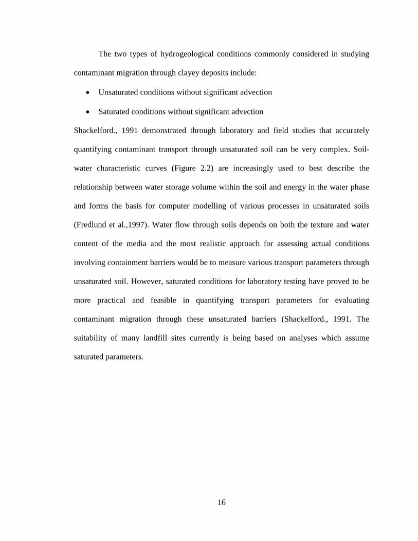
Shackelford., 1991 demonstrated through laboratory and field studies that accurately
quantifying contaminant transport through unsaturated soil can be very complex. Soil-
water characteristic curves (Figure 2.2) are increasingly used to best describe the
relationship between water storage volume within the soil and energy in the water phase
and forms the basis for computer modelling of various processes in unsaturated soils
(Fredlund et al.,1997). Water flow through soils depends on both the texture and water
content of the media and the most realistic approach for assessing actual conditions
involving containment barriers would be to measure various transport parameters through
unsaturated soil. However, saturated conditions for laboratory testing have proved to be
more practical and feasible in quantifying transport parameters for evaluating
contaminant migration through these unsaturated barriers (Shackelford., 1991. The
suitability of many landfill sites currently is being based on analyses which assume
saturated parameters.
Page 28
17
Fig. 2.2 Hysteresis of wetting and drying branches of a soil moisture characteristic curve (Barbour et al.,2005).
Page 29
18
Two important vadose zone properties related to the hydrological water balance
are the total amount of the water held in the vadose zone and the estimated annual flux.
Intense rainfall events typical of semi-arid zones recharge events can cause surface
flooding and transport through larger pores and cracks (macropores) even though the soil
is not fully saturated. A key question raised by Close (2010) is whether solutes that enter
the groundwater in response to recharge events come from that recharge event and travel
right through the vadose zone, or are already present in the vadose zone and correspond
to recharge from a previous time or a mixture of both. Close (2010) added that the type
of recharge process depends on the type and intensity of the recharge event and the
textural characteristics of the vadose zone material but is usually difficult to determine as
it is difficult to distinguish between contaminants from charge times. This becomes an
important point for consideration of leachate generation and migration potential during
the operating life of the landfill when interim or final covers have not yet been placed
over the waste at landfill sites.
2.5 Contaminant Attenuation Phenomenon
Attenuating processes identified in the unsaturated zone include gas exchange,
immiscibility, filtration, biochemical and chemical degradation. Sorption of a
contaminant in the vadose zone is one of the significant processes that can hinder the
transport of contaminants into the ground water aquifer system. The amount of
adsorption that occurs is a function of the solute concentration and the amount of solute
sorbed onto soil particles and /or organic matter (O’kane., 2009).
Other potential attenuation mechanisms are attributed to precipitation, biological
oxidation of organic contaminants and radioactive decay (Rowe., 1987). Sililo (1997)
Page 30
19
studied the migration and attenuation of organic contaminants in the unsaturated zone
through field experiments in South Africa and demonstrated the ability of organic
contaminants to move rapidly through the unsaturated zone with little attenuation. Sililo
stressed the need for extreme caution while making assumptions on the ability of the
unsaturated zone to attenuate and immobilise organic contaminants. The interrelationship
between geology, hydrogeology, and groundwater hydraulics form the basis on which the
primary mechanisms of transport are quantified to assess barrier performance (Shaw and
Hendry., 1998). According to Quigley et al., (1987) the mobility of a chemical species in
soil is a complex function of the soil matrix, the mass, radius, valence, concentration, and
the viscosity, dielectric constant and temperature of the diffusing medium. As noted
above, attenuation of contaminants through natural clay barriers occurs through complex
processes and may be difficult to accurately quantify, however, due to the lowering of
environmental and health risks that are associated with any attenuation of contaminants,
studying the filtration potential of these soils continues to be of significant importance.
Even as there are immediate benefits from the vadose zone acting as a filter
medium, long term fixation of various chemical constituents in previously
uncontaminated soils at landfill sites and any long term negative impacts to the
environment is a growing concern. Historically, environmental concerns at sanitary
landfill sites have largely focused on potential impacts to groundwater systems beneath
and have escaped the same scrutiny that is being more recently afforded to soil
contamination, for example under contaminated sites regulations in British Columbia.
Page 31
20
2.6 Landfill Liner Design and the Regulatory System
Historically, landfills in the arid west were not anticipated to generate enough
leachate to impact local groundwater systems. Experience now shows that this
assumption may have been wrong and in order to minimize negative impacts to the
environment and mitigate legal risks, many jurisdictions have developed a regulatory
framework (WDEQ, 2009). Rowe (2005) has pointed out how the declaration of a State
of Emergency at Love Canal, NY, in 1978, and the subsequent evacuation of 236 families
from homes around the landfill, has brought into focus the potential risks associated with
landfills and the need for regulations to control siting, design and operation of these
facilities.
Internationally, landfill classification methodologies have been developed under:
1) Prescriptive Classification systems
2) Performance based classification systems
3) Effects/risk based classification systems
4) Combination of different systems
As an example, in New Zealand these classification methodologies (Fig.2.3) are not
intended to be used to set standards for landfill siting, design or operations, but rather to
define those landfills with the appropriate level of environmental protection, through
siting, design and operational characteristics, for the different waste acceptance criteria
(NZMFE,2001).
Page 32
21
Figure 2.3 Typical approaches to landfill classification (NZMFE., 2001).
Page 33
22
Prescriptive performance-based design standards for environmental control is the
norm in many countries. In the United States regulations have been developed for
municipal waste landfills under the Resource Conservation and Recovery Act and there
are two types of Landfill liner design philosophies: the design standard and the
performance standard (Workman and Keeble, 1989). In Canada, according to a summary
provided by Estrin and Rowe (1995) on landfill design and the regulatory system the
following categories were identified:
1) Essentially no regulation
2) Prescriptive regulations that specify minimum design requirements
3) Performance based regulations
4) Regulations requiring negligible impact in perpetuity
Prescriptive design standards are advantageous to regulatory agencies from a
compliance perspective, in that design specifications can be easily verified, however they
can be disadvantageous as formula specifications may not be able to ensure minimum
environmental impact and elimination of long term liabilities especially in complex
hydrogeological environments (Estrin and Rowe, 1995).
Performance standards have been reported to have a number of benefits such as
encouraging design innovation and flexibility, but they come with having to try out
unproven technology. Overall it is felt that there are benefits to tailoring designs to meet
particular hydrogeological environments that demonstrate the maximum potential for
satisfactory site-specific performance and are preferable to prescriptive engineering
design specifications that can result in undervaluing potential environmental impacts and
legal risk (Estrin and Rowe, 1995).
Page 34
23
Provincial governments across Canada have adopted different prescriptive
standards for landfill liner design and construction and some of the standards are
summarized below:
1) Prince Edward Island under their Waste Resource Management Regulations have a
comprehensive list of design and construction requirements that stipulate landfills to
install a composite liner system comprising of a 1m thick compacted clay in conjunction
with a 80 mil HDPE geomembrane. The minimum hydraulic conductivity is to be 1x10⁻⁷
cm/sec or less and the maximum allowable leachate head above the liner is 300 mm. The
regulations also include a detailed Quality Control and Quality Assurance Plan.
2) In British Columbia, the Ministry of Environment (BCMOE) follows a more risk
based approach and allows "natural control" landfills which do not rely on leachate
containment/collection/disposal systems and engineered landfills to be constructed. For
Natural control landfills there is to be at least a 2m thick layer of low permeability soil
with a hydraulic conductivity of 1 x 10⁻⁶ cm/s or less (i.e. silt or clay), below each of the
bottom-most waste cells. Lesser thicknesses or no layer of low permeability soil may be
approved based on the potential for leachate generation and the unsaturated soil depth,
permeability and leachate attenuation capability of the natural soil. The waste cell is to be
situated 1.2 m above the seasonal high water table and variation in depths may be
allowed based on soil permeability and the leachate attenuation potential of the soil.
For Engineered Landfills BCMOE specifies minimum liner requirements for
leachate containment system using a 1 m thick, compacted soil liner with a hydraulic
conductivity of 1 x 10⁻⁷ cm/s or less. Natural, in-situ, low permeability soils,
geomembranes, or composite liners (consisting of a geomembrane and a soil layer) that
Page 35
24
provide the same level of leachate containment are also acceptable equivalents and liners
with higher hydraulic conductivities may be approved depending on the leachate
generation potential and the unsaturated soil depth, permeability and leachate attenuation
capacity of natural soils (BCMOE, 1993).
3) Nova Scotia requires that their landfills liners consist of the following components: a
bottom liner and leak detection system, soil liner component, flexible membrane liner,
leachate collection layer and a cushion layer. Again the hydraulic conductivity of the soil
liner is an important design parameter and is stipulated to 1x10⁻⁷ cm/sec or less. The
flexible membrane liner component is a HDPE 60 mil liner. The guidelines also stipulate
that an alternate liner system may be used but after approval of a detailed analysis of the
proposed system including computer modeling using POLLUTE (Rowe et al., 1994). A
typical cross section of the Liner system specified under the Nova Scotia Municipal Solid
Waste Guidelines is provided in Figure 2.4.
Page 36
25
Figure 2.4 Typical cross-section of liner system (Nova Scotia Landfill Guidelines-2004)
Page 37
26
Alberta Environment Guidelines have more stringent requirements and stipulate
that new landfills or expansion areas as a minimum be situated at a location where there
is a 5 m thick layer of a natural clayey deposit having an equivalent hydraulic
conductivity less than 1 x 10⁻⁶ cm/sec; and in addition has a liner system that has a
hydraulic conductivity of less than 1 x 10⁻⁷ cm/sec to a thickness of not less than 1 m,
measured perpendicular to the slope, or an alternate layer that has a hydraulic
conductivity greater than 1 x 10⁻⁷ cm/sec to a thickness greater than 1 metre that will
achieve an equivalent advective performance. In the case of composite liners, the liners
are to be constructed with a geomembrane placed directly on the surface of a liner that is
comprised of earthen material with a hydraulic conductivity of less than 1 x 10⁻⁷ cm/sec
compacted to a thickness of not less than 0.6 m, measured perpendicular to the slope, or a
liner that is comprised of earthen materials with a hydraulic conductivity greater than 1 x
10-7 cm/sec compacted to a thickness greater than 0.6 m and will achieve an equivalent
advective performance. Alberta guidelines also allow for a performance standard
approach where the landfill operator can provide evidence that groundwater quality will
not exceed the performance standards at compliance points. Compliance points are to be
at a minimum of 20 metres within the property boundary of the landfill and a minimum
of 10 metres, but not more than 60 metres from the waste footprint. The performance
standard approach generally allows for more innovation, flexibility and design
modifications to suit the local hydrogeological environment.
Page 38
27
In summary the use of prescriptive design standards tends to the preferred
approach for landfill regulations across North America and Europe. There are multiple
components that form part of the design and are as follows:
1) low values of K typically ranging from 1 x 10⁻⁷ cm/sec to 1 x 10⁻⁶ cm/sec to
inhibit contaminant migration through barrier systems solely based on
advective flow.
2) A leachate collection system that has adequate drainage potential to keep the
leachate head at the base of the landfill to approximately 0.3m to 1m.
3) Natural or engineered composite barriers with or without a geomembrane with
a thickness ranging from 0.6m to 5m thick or a combination thereof.
4) A final cover system designed with low permeability materials to limit
infiltration.
The review suggests that all of the design specifications recommended under
various regulations the world over are centered around leachate containment using
advective barriers and creation of a “dry tomb” landfill for permanent burial of waste
and ongoing research in the industry plays an important role in the type of design
standards adopted. The discussion around long term inadequacy of advective barrier
systems and the need to shift towards diffusive barrier systems is now emerging since it
is well established that at very low advective velocities typical of clayey soils, diffusive
fluxes dominate contaminant movement (Quigley et al., 1987; Goodall and Quigley.,
1977; Desauliners et al., 1981; Schakelford and Daniel., 1988; Gray and weber., 1984 )
and the release of contaminants may occur from molecular diffusion across the barriers.
Page 39
28
Therefore a barrier which allows escape of pollutants only by molecular diffusion is the
best that can be built (Schakelford, 1988).
The long term performance of earthen barriers also depends directly on barrier
leachate interaction and its effect on the hydraulic conductivity of the barrier material.
Whether or not the permeating liquid causes changes to the hydraulic conductivity
depends on leachate constituents (Fernandez and Quigley, 1985, 1988; Shackelford,
1994; Shackelford et al., 2000; Rowe et al., 2004; Lee et al., 2005). Chemical
incompatibility may increase the saturated hydraulic conductivity of the soil by inducing
cracking due to shrinkage of the clay potentially causing undesirable release of
contaminants into the surrounding environment. Rowe (2007) showed that volatile
organic compounds can also diffuse through high-density polyethylene (HDPE)
geomembranes in as little as a few days to a few weeks. It was reported that VOCs
migrated through a 0.6m thick composite liner in 1 to 2 yrs. (at 1 percent of the source
concentration) or 4 years (at 10 percent of source concentration). In general
geomembranes used in the composite liners provide minimum resistance to diffusion of
volatile organic compounds.
Even as the use of diffusive barrier design standards seem more beneficial it may
well be that permeability continues to be the norm since diffusion testing of unsaturated
soils is more complex and expensive and the shift is only beginning to happen. In reality,
every diffusive barrier naturally performs as a good advective barrier but not every
advective barrier acts as a good diffusive one. In arid and semi-arid zones with its
Page 40
29
characteristic low annual precipitation and diffusion is a dominant transport mechanism
and cannot be overlooked.
The Saskatchewan Environmental Code landfill guidelines which forms the basis
for analysis used in this study, with its comprehensive risk based approach seems well
balanced and is at the moment one of the leading landfill guideline documents in Canada.
Page 41
30
Figure 2.5. Landfill barrier systems in different countries of the world (ISSMFE TC5, 1997)
Page 42
31
2.7 Numerical Modelling of Leachate Migration
Numerous mathematical models have been developed to simulate processes
governing leachate occurrence and behaviour in landfills. The emphasis of these models
has generally been on estimating leachate quantity and quality in order to control its
associated environmental impacts, particularly on ground water pollution. In general,
modeling transport of solutes in the vadose zone is complex as water and contaminants
are typically dispersed at fluctuating velocities through dissimilar pathways.
Preferential pathways resulting from sub-surface erosion, fractures and soil shrinkage
cracks may transmit water and solutes at much higher rates than those predicted by
numerical models. The common modeling assumption that the Soil medium is
homogenous generally leads to oversimplification of transport problems.
However, numerical modelling of leachate migration has been shown by many
researchers to be an integral part of landfill liner design and performance evaluation and
is an effective tool for study of various interactions in clay-water systems at landfill sites
(Rowe et al., 1985., William et al., 1982; El-Fadel et al., 1997; Rowe and Sawicki.,
1992). The transport models in current use have all largely been derived from the
common hydro geological equation of advection/dispersion and adsorption.
A vast array of numerical schemes have been presented by many researchers
(Rowe and Booker., 2000; Miller and Benson.,1983; Heinrich and Zienkiswicz.,1979;
Addiscott.,1984; Goltz and Roberts.,1988; Dagan and Bresler.,1979). Maciejewski
(1993) from his numerical and experimental study of ionic solute transport in unsaturated
soils showed the linear dependence of the dispersion coefficient on the water content for
a constant pore-water velocity. Conca and Wright (1992) demonstrated that the effective
Page 43
32
diffusion coefficients in gravel, soil and whole rock to be primarily a function of
volumetric water content and not material characteristics. Leachate movement within
landfills modelled on unsaturated flow principles has gained more attention but may
come with an inherent level of oversimplification of actual transport phenomenon
(Rucker, 1998; Schroeder et al. 1994).
Page 44
33
3.0 MODELLING OF CONTAMINAMT CONTAINMANT POTENTIAL
3.1 Local Subsurface Geology
The original Fleet Street Landfill and expansion areas overlie two very important
regional aquifer systems consisting of the upper Condie aquifer and the lower Regina
aquifer. It is reported that the two aquifers are separated by a till aquitard 26 to 30 m
thick (City of Regina, 1980). The Regina Aquifer is source of water for a number of
commercial, industrial and domestic wells in the vicinity of the landfill. The Condie
Aquifer is a continuous, permeable to highly permeable, generally unconfined aquifer
with the thickest depths reported to range between 20 – 30 m. According to the City of
Regina (2009) there are very few licensed groundwater and surface water users within 2
km radius of the Fleet Street Landfill. Of those, only Consumers CO-OP Refinery CCRL
is considered a major user four wells are licensed for 3900 dam3/year. CCRL and CBR
Cement Ltd are the only groundwater users within 2 km that extract groundwater from
the Regina Aquifer. Towns outside of the City of Regina such as Pilot Butte and White
City are some of the major Condie Aquifer groundwater users.
The stratigraphic interpretations of the Regina area are well documented by
Christiansen (1969) and are generally based on the sequence of tills, inter-till deposits,
and pre-glacial sediments. The subsurface geology reported at the Fleet street landfill site
includes successive layers of 1.5m to 6m thick glaciolacustrine silty clay , 1.5m to 10m
thick oxidized clayey till, 1m to 2.5m of sand and gravel, 28m to 30 m of clayey till of
which the upper 6m is oxidized, about 0.6m of sand and gravel and about 22m of clayey
un-oxidized till over clay shale (Lissey., 1962). The detailed geological and hydrological
setting or the Regina area developed by Christiansen (1979) is represented in Figure 3.1.
Page 45
34
Figure 3.1. Schematic geological and hydrological setting or the Regina area (cited after Ballagh, 1998)
Page 46
35
The landfill drilling program conducted by the City of Regina (1980) has
confirmed the general overview of the local landfill site subsurface geology and presence
of an upper aquifer throughout the landfill area. Surficial clay as part of the unsaturated
zone is said to extend throughout the landfill site and ranges in thicknesses of 11 to 23m.
a site plan of the landfill site is provided below in Fig. 3.2 .
3.2 Extent of Aquifers and Groundwater Quality Impacts The landfill site is located in an area where two major aquifers are existent. The
Condie Aquifer consisting of silt, sand and gravel and the Regina Aquifer. The Condie
Aquifer overlies a layer of till which separates it from the Regina Aquifer. These
aquifers receive recharge from infiltrating precipitation which is not likely to exceed 5%
of the total annual amount which averages 38 cm per year (City of Regina., 1980). The
aquifer systems existing below the landfill site is shown in Figure 3.3.
In terms of groundwater quality impacts, it has been reported that groundwater
quality impacts have occurred over the last forty years. There are increasing trends in
sodium, chloride and TDS contamination and levels above background concentrations
have been found (City of Regina., 2009). According to Ballagh (1998) TDS levels at the
site have increased and are as high as 2140 mg/l in comparison to a background
concentration of 826 mg/l, whereas chloride levels are reported to show a decreasing
trend.
Page 47
36
Figure 3.2. Fleet Street landfill site plan including expansion area (City of Regina, 2009)
Page 48
37
Figure 3.3. Condie and Regina Aquifer profiles beneath the landfill site (City of Regina, 2009)
Page 49
38
3.3 Modelling Program
The modeling program investigated the contaminant containment potential of a
composite landfill liner system in conjunction with the naturally occurring
glacioacustrine clay barrier at the Regina landfill expansion site. The type of landfill liner
design employed would play an important role in limiting contaminant mass fluxes into
the vadose zone, and eventually the underlying aquifer. The simulated contaminant
containment potential helps us understand the implications of applying prescriptive
engineering design specifications versus performance standards towards landfill liner
design at the Regina Landfill site in accordance with the Saskatchewan Environment
Code (SEC) Landfill Regulations.
In keeping with the design philosophy prescribed under the SEC the transit time
was calculated for the different landfill design types and compared to simulations using
two commercially available one-dimensional modeling software programs: VZCOMML©
a one-dimensional, steady-state, equilibrium partitioning vadose zone model was used to
simulate advective flows and CHEMFLUX, a commercially available finite element
software developed by Soilvision Systems Limited was used to simulate 1-D diffusive
contaminant transport.
The SEC requires that the plug flow transit time be calculated to assess the
sensitivity to groundwater contamination at the location of a landfill site with the
following considerations:
Page 50
39
(a) the calculation is to be made using the hydraulic gradient measured for relevant ions
(b) the hydraulic head above the liner is to be estimated based on worst-case long-term
leachate head over the liner considering clogging induced reduction in hydraulic
conductivity of the leachate collection and removal system’s drainage layer
(c) the calculation for plug flow transit time is to be made ignoring the effects of
diffusion/dispersion or retardation and consider only the hydraulic conductivity of the
various natural stratigraphy units; and finally
(d) in all cases, where one or more geomembrane and/or geosynthetic clay liner is used
for the seepage barrier system, the calculation for plug flow transit time is to be made
ignoring the effect of geomembrane and/or geosynthetic clay liner.
The SEC design standards target very low advective velocities to act as the
primary mechanism to control migration of contaminants into the aquifer system,
however it is well established that at very low advective velocities typical of clayey soils
such as found at the subject site, diffusive fluxes can dominate contaminant movement
(Quigley et al., 1987, Goodall and Quigley, 1977; 1988, Gray and Weber).
Hence the second part of the modeling investigation included a simulation using
CHEMFLUX, a commercially available finite element software developed by Soilvision
Systems Limited for 1-D diffusive transport assessment.
Page 51
40
Table 3.1. Description of landfill design types as per Saskatchewan Environmental Code (2011)
Design Type Base & Side Seepage Barrier System Leachate Collection System
2A - Natural attenuation landfill No constructed seepage barrier requiredNo leachate collection and removal systytem required
2B - Improved natural attenuation landfill No leachate collection and removal systytem required
2C-Natural containment landfill with leachate collection No constructed seepage barrier required
Leachate collection and removal system designed to
collect minimum flow rate of 0.15 m3/yr per sq.m and control leachate head to less than 1m
2-D Engineered containment landfill with leachate collectionleachate collection and removal system designed to collect minimum flow rate of 0.15 m3/yr per sq.m and control leachate head to less than 0.3 m
2E-Engineered containment landfill with leachate collection Leachate collection and removal system designed to collect minimum flow rate of 0.15 m3/yr per sq.m and control leachate head to less than 1m
2F-Composite liner engineered containment landfill with leachate collection
Leachate collection and removal system grading and collection pipe designed to ontrol leachate head to less than 0.3m
2G- Double Composite liner engineered containment landfill with leachate collection
Leachate collection and removal system grading and collection pipe designed to ontrol leachate head to less than 0.3m
Page 52
41
Table 3.2 Selection of landfill design type based on site sensitivity, waste type and landfill size (SEC 2011)
Criteria* Type II Waste(X) (Y) Landfill Size Very Small Small Medium Large All sizes
Site Tonnes Per Year < 750 750- 2500 >2500 - 20000 >20000Sensitivity
Tonnes In Place < 15000 15000-70000 >70000 - 400000 > 400000for entire life of landfill
Low >15 >100 2A 2A 2C
Medium 8.0 - 15.0 30 - 100 2B 2D 2E
High < 8.0 < 30 NA 2E 2FNOTES:
* In case where the criterion (X) and (Y) leads to assessment of different sensitivity: the higher site sensitivity criterion should be used inselecting a generic desgn type
**under situations where a hydraulic connection between underlying perched aquifer and usable aquifer is evident and plug flow transit time is as per column (Y), the design type shall only be either 2E, 2F or 2G.
Type I Waste
Distance between underlying useable
aquifer and the lowest base
proposed for the landfill in meters
For all types of TPY and TIP
Generic Design Type**
2E
2F
2G
Page 53
42
3.4 Evaluation of Transit Time
Under the SEC one of the key considerations for landfill performance is the
evaluation of transit time for a known concentration of a specific contaminant to migrate
from the base of the liner. Transit time calculations were initially completed using a
rather conservative SEC approach without the effects of retardation, dispersion or
diffusion using VZCOMML. Following this approach a less conservative methodology
presented by Schakelford (1990) using an analytical solution to the one-dimensional
advection dispersion equation for solute transport in saturated soil was used. Shackelford
(1990) presented the analytical solution in the following form:
𝑐𝑐0
= 12
[𝑒𝑟𝑓𝑐 � 1−𝑇𝑅
2�𝑇𝑅 𝑃𝐿�� + 𝑒𝑥𝑝 (𝑃𝐿) ∙ 𝑒𝑟𝑓𝑐 � 1−𝑇𝑅
2�𝑇𝑅 𝑃𝐿�� ] ………1
Where c is the concentration of the solution at the base of the landfill, 𝑐0 is the
contaminant concentration at the compliance point, 𝑇𝑅 is a dimensionless time fator and
𝑃𝐿 is a dimensionless factor known as the peclet number.
The calculation follows the detailed steps discussed by Schakelford (1990):
− Determination of the constants of the calculation (I: hydraulic gradient, K: hydraulic
conductivity, n: porosity, c: allowable concentration at the base of the landfill at time t,
c0: concentration at compliance point D*: effective dispersion coefficient of the
contaminant, Rd: retardation coefficient),
Page 54
43
− Determination of the seepage velocity (𝑉𝑠 ) in the pore volume:
𝑉𝑠 = 𝐾.𝐼𝑛
…………2
− Estimation of L (required barrier-thickness) which ensures that the concentration on the
protected site is lower at time t then the recommended drinking water guideline,
− Determination of the Peclet Number 𝑃𝐿 :
𝑃𝐿 = 𝑉𝑠 ∙ 𝐿𝐷∗
………..3
− Determination of c/c0 value and from Fig. 3.4 determine the TR value using the
previously calculated c/c0 and PL values,
− The average transport time 𝑡1 of the pollutant is calculated using
𝑡1 = 𝑇𝑅∙𝑅𝑑∙𝐿𝑣𝑠
………..4
The results of the transit time calculation are presented in the next section under Tables
4.2 to 4.3. A Sensitivity analysis was also carried out by varying contaminant
concentrations and varying liner thicknesses.
Page 55
44
Fig. 3.4 The relationship of dimensionless parameters and the relative concentration (Shackelford, 1990)
Page 56
45
3.5 VZCOMML Model
The VZCOMML software developed by Washington Savannah River Company
for The United States Department of Energy is routinely used to perform vadose zone
contaminant fate and transport analysis in a manner that complies with Subtitle D
protocols specified by USEPA. The model also has the ability to calculate protective soil
threshold levels and future clean-up goals should the soils beneath the landfill site be
contaminated due to liner failure.
The model estimates the mean travel time in the vadose zone for Chloride to
arrive at the base of the vadose zone, the maximum groundwater concentration at a
receptor location on the edge of the waste unit, and the maximum contaminant
concentrations in soil that will not exceed the maximum contaminant level. In this case
the MCL from Saskatchewan Drinking Water Standards for chloride in groundwater were
used.
The one-dimensional model is able to simulate liquid-phase advection, liquid and
vapor-phase dispersion, sorption, and decay of the contaminant. It uses a simple mass-
balance technique to estimate the mixing of the vadose-zone contaminant with
groundwater. The model also handles vertical heterogeneity of the soil column. The
mean travel retarded contaminant travel time in the vadose zone is calculated using the
following equation (Rucker 2011) :
𝑇𝑚𝑒𝑎𝑛 = 𝐿𝑉∙𝑅𝑉𝑆
……5
Where: 𝑇𝑚𝑒𝑎𝑛 is the mean travel time to the top of the aquifer, 𝐿𝑉 distance from the
bottom of source layer to the water table, 𝑉𝑆 is the pore water velocity in the vadose zone
and 𝑅 is the retardation coefficient. The pore water velocity is determined from the
Page 57
46
infiltration rate, total and effective porosity, and the saturated hydraulic conductivity
through the series of these equations:
𝑉𝑆 = 𝐼𝜃𝑒
…….6
𝜃𝑒 = 𝜃𝑤 ∙𝑛𝑒𝑛𝑡
…….7
𝜃𝑤 = 𝑛1 ∙ �𝐼𝐾𝑆�� 1
(2∙𝑏+3)�……8
Where:
Vs Soil-pore water velocity in vadose zone
I Vertical infiltration rate through vadose zone
𝜃𝑤 Volumetric moisture content (Vwater/Vsoil) Fraction
𝜃𝑒 Effective moisture content Fraction
𝑛𝑒 Effective porosity Fraction
𝑛𝑡 Total porosity Fraction
b Soil-specific exponential parameter
Ks Saturated hydraulic conductivity
Page 58
47
3.6 Modelling Assumptions
The major assumptions used in the model are:
1. The contaminant source is considered to be infinite.
2. The system is at equilibrium with respect to adsorption.
3. Contaminants are homogeneously distributed in the vadose zone.
4. Adsorption is linear with concentration.
5. Contaminant adsorption to soil is reversible (Rucker 2011).
Darcy’s Law governs transport in the vadose zone and is based on mean flow.
Maximum acceptable Chloride concentrations (3000mg/Kg) in soil permitted for disposal
at the Regina Landfill site as per SEC were used as the baseline estimate for soil
concentrations within the transport analysis. And dispersion was not incorporated into
VZCOMML transport calculations. The effects of using recurrent layers of high
moisture content low permeability clays for daily cover that likely cause periodic
accumulation of leachate are not taken into account in the model. Similarly any reduction
in contaminant source concentrations due to increased infiltration, leachate treatment and
offsite disposal were also not incorporated into the model.
Page 59
48
Figure 3.5 Conceptual diagram of vadose zone contaminant migration model (EPA, 2011)
Page 60
49
Figure 3.6 Concept diagram representing three different models used in the study
Page 61
50
3.7 Predicting Chloride Migration
The simple soil screening model can account for soil type and hydraulic
conductivity for up to four different soil layers and calculates a travel time through the
vadose zone based upon a calculated pore-water velocity and retardation factor. First-
order decay rates for both organic and radioactive contaminants can be incorporated into
the model. The model estimates a peak groundwater concentration directly adjacent to the
waste site and compares it to the maximum contaminant level (MCL). The software has
the capability to simulate transport for up to 187 contaminants simultaneously in one
execution and includes volatile, semi-volatile, metal and radionuclide analytes. The
program has also been designed to minimize extensive, expensive and complex data
inputs.
3.8 CHEMFLUX Model
CHEMFLUX, a commercially available finite element software developed by
Soilvision Systems Limited was used to simulate 1-D contaminant transport from the
Regina Landfill expansion site. Transport of contaminants were evaluated from the base
of the landfill to the top of the low lying Condie aquifer. The model layering of the
vadose zone was mirrored on previous studies conducted at the subject site by O’Kane
Consultants in 2009. It consisted of a 7m thick hetrogenous soil layer based on actual site
stratigraphy. For the one-dimensional model the geometrics were obtained from the City
of Regina Landfill Expansion Study (AMEC, 2009). The model was first set up in
SVFlux a finite element numerical model that executes 1-D, 2-D and 3-D boundary value
seepage problems and then imported into CHEMFLUX. SVFLUX solves the general
partial differential equation for transient and steady state saturated and unsaturated
Page 62
51
seepage problems through porous media. The CHEMFLUX model has automatic mesh
generation and visual output.
3.8.1 CHEMFLUX Model Development and Inputs
The CHEMFLUX 1-D model was developed based on extensive lithological
information available form ongoing monitoring activities carried out by the City of
Regina since the inception of the landfill operations in 1961. The 1-D transient model
consists of a 1m thick clay liner and 7m thick vadose zone made of clay, silt and sand.
Three scenarios were modeled: the first one includes a geomembrane liner, the second
without and the third with a leaky membrane. The leaky membrane was simulated using
an equivalent leakage based on a worst case scenario where the contact with the soil is
poor, and 17 rectangular defects were assumed per hectare (O’Kane 2009). Simulations
were carried out for 10, 25, 45, 65, 80 and 100 years. Inputs for material properties into
the CHEMFLUX model have a major role to play in resulting contaminant transport
predictions and are summarized below in Table 3.6.
Page 63
52
Figure 3.7 CHEMFLUX model mesh used to simulate 1-D contaminant transport at the landfill expansion site
Page 64
53
Table 3.3 VZCOMML 1-D Model Inputs
VZCOMML Soil Column Data Summary Input Parameters Value Units
Depth of Contamination 3 ds [m] Bottom of Source Zone to
Top of Water Table 7 Lv [m] Total Depth Soil Column 9.3 Tc [m]
Water-filled porosity 35.09% θw [%] wt avg Air-filled porosity 10.58% θa [%] wt avg
Effective moisture content 31.68% θe [%] wt avg Total Porosity 44.00% nt [%] wt avg
Unretarded Pore-water Velocity from
Source Zone Bottom to Aquifer 0.23 [m/yr] Unretarded Travel Time from
Bottom of Source Zone to Aquifer 58.07 [yrs] Unretarded Pore-water Velocity
for Entire Soil Column 1.41E-01 Vs [m/year] wt avg Unretarded Travel Time for
Entire Soil Column 65.48 Tt [yrs] Chloride Total Soil Concentration (Ct) 3000 mg/kg
Saskatchewan Drinking Water Action Level 250 mg/L
Table 3.4 Material Parameters
Material Porosity
Saturated Hydraulic Conductivity (K)
cm/Sec
Diffusion Coefficients (D)
cm2/sec Target Liner Design
value 0.6 1.00E-07
HDPE Membrane 0.1 2.00E-13 Regina clay 0.6 1.00E-07* 4.98E-06**
Compacted Regina clay 0.6 5.00E-08 4.00E-07 Municipal Solid Waste 0.4 1.00E-03 2.00E-04
Condie Aquifer 0.35 4.00E-03 Silt 0.38 3.00E-05
Fine sand 0.35 4.00E-04 Till 0.34 1.00E-06
* K values are from experimental data after O’Kane 2009 ** D values for undisturbed Regina Clay samples after Yatkwong and Dennis, 1987.
Page 65
54
4.0 RESULTS AND DISCUSSSION
VZCOMML and CHEMFLUX models were applied to predict chloride migration
through the liner and the underlying vadose zone. Different design scenarios prescribed
under the Saskatchewan Environment Code for landfills were modeled to assess the
efficacy and relevance of the current liner design at the Regina Landfill Expansion site.
Results of the modelling investigation are reported below.
The VZCOMML one dimensional soil screening model depicts a hetrogenous soil
column arranged perpendicular to the ground-water flow direction. The vadose zone soil
is divided into three soil layers whose total effective porosity decreases from 0.60 to 0.34
and moisture content ranges from 0.67 to 0.27 along with the depth as shown in
Figure.3.7. Results of Chloride migration based on a soil concentration of 3000 mg/L at
the base of the landfill are summarised in Table 4.1. Non Retardant species such as
Chlorides tend to remain at the same concentration through the Vadose zone and
concentrations will begin to decrease once it reaches the saturated zone due to natural
attenuation and reductions in contaminant concentration by dilution or transfer to another
medium. It is inferred that in four out of the seven landfill design scenarios modeled,
from type 2A to type 2D, chloride concentrations reach the performance monitoring well
station between 22 and 87 years. In the case of design type 2A with only the natural
attenuation layer the chloride concentration decreases to 207 mg/L within 44 years which
is within the operating lifespan of the facility. The performance of design types 2E, 2F
and 2G are primarily controlled by the hydraulic conductivity of the geomembrane liner
and were based on values of 2.1 x 10ˉ13 cm/sec. At these extremely low permeability
values the model predicts migration rates into thousands of years and depicts negligible
Page 66
55
advective flux. These extremely low values of K will inhibit contaminant migration due
to the advective component of flow. However it is well established that at low advective
velocities typical of clayey soils, diffusive fluxes will dominate contaminant movement
(Quigley et al., 1987, Goodall and Quigley,1977; Desauliners et al., 1981, Schakelford
and Daniel, 1988, Gray and weber., ). Hence design types 2E, 2F and 2G were
subsequently modeled as diffusion barriers using the CHEMFLUX model.
The representative height of the source zone used in the model of 3m is not
indicative of the actual height of leachate mounding which can vary quite significantly
within the landfill but is used a representative height to quantify mass of contaminant
available for migration. The results of the CHEMFLUX chloride transport model are
presented on Figures 4.1 to 4.16. Over the planned life of the landfill of 80 yrs, results
show that the geomembrane aids in reducing initial chloride concentrations by about 50%
at 1m below the base of the landfill. In the absence of a geomembrane, chloride
concentrations reach 30% of its initial concentration to depths of about 2m during the
same time period. In terms of equivalent performance the geomembrane adds about 1m
of additional protection similar to the natural clay layer.
Assuming there are no preferential pathways for contaminants to directly reach
the aquifer, the natural clay barrier serves as an effective advective/diffusive barrier
and concentrations matching Saskatchewan Drinking Water Standards reach the aquifer
only after hundreds of years.
Page 67
56
Table 4.1 VZCOMML Results on SEC Design types
Saskatchewan Environment Code
Initial Soil Concentration Travel Time
Predicted Chloride Groundwater Concentration
Landfill Design Type (mg/Kg) (years) (mg/L)2A 3000 50.00 142.002B 3000 72.00 121.002C 3000 70.00 284.002D 3000 106.00 79.00
2D-with Geomenbrane 3000 Exhibits Diffusive Barrier Chartecteristics2E*-with Geomenbrane 3000 Exhibits Diffusive Barrier Chartecteristics2F*-with Geomenbrane 3000 Exhibits Diffusive Barrier Chartecteristics2G*-with Geomenbrane 3000 Exhibits Diffusive Barrier Chartecteristics
*Refer CHEMFLUX Results
Page 68
57
Table 4.2 Transit Time Evaluation
Description UnitC mg/L 250 250 250 250 250 250
CO mg/L 3000 3000 3000 3000 3000 3000
C/C0 0.0833 0.0833 0.0833 0.0833 0.0833 0.0833
LINER THICKNESS L m 1 1.5 2 2.5 3 3.5
Natural Attenuating layer m 7.3 7.3 7.3 7.3 7.3 7.3
PECLET NUMBER 6.51E-02 9.76E-02 1.30E-01 1.63E-01 1.95E-01 2.28E-01
TR 0.01 0.05 0.015 0.02 0.03 0.04
TRANSIT TIME t Yrs 9.79 73.40 29.36 48.93 88.08 137.02
Rd(non -reactive solute) 1 1 1 1 1 1
K (Regina Clay) cm/sec 2.00E-08 2.00E-08 2.00E-08 2.00E-08 2.00E-08 2.00E-08Effective Porosity 0.5 0.5 0.5 0.5 0.5 0.5
Vs -Seepage velocity cm/sec 3.24E-09 3.24E-09 3.24E-09 3.24E-09 3.24E-09 3.24E-09Hydraulic gradient 0.081 0.081 0.081 0.081 0.081 0.081
D* cm2/sec 4.98E-06 4.98E-06 4.98E-06 4.98E-06 4.98E-06 4.98E-06
Design Life of the Landfill Yrs 80 80 80 80 80 80
TRANSIT TIME EVALUATION THROUGH LINER
Page 69
58
Table 4.3 Transit Time Evaluation – Leachate Removal/Treatment
Description UnitC mg/L 250 250 250 250 250 250
CO mg/L 500 500 500 500 500 500
C/C0 0.5000 0.5000 0.5000 0.5000 0.5000 0.5000
LINER THICKNESS L m 1 1.5 2 2.5 3 3.5
Natural Attenuating layer m 7.3 7.3 7.3 7.3 7.3 7.3
PECLET NUMBER 6.51E-02 9.76E-02 1.30E-01 1.63E-01 1.95E-01 2.28E-01
TR 0.06 0.1 0.18 0.2 0.22 0.24
TRANSIT TIME t Yrs 58.72 146.80 352.33 489.35 645.94 822.11
Rd(non -reactive solute) 1 1 1 1 1 1
K (Regina Clay) cm/sec 2.00E-08 2.00E-08 2.00E-08 2.00E-08 2.00E-08 2.00E-08Effective Porosity 0.5 0.5 0.5 0.5 0.5 0.5
Vs -Seepage velocity cm/sec 3.24E-09 3.24E-09 3.24E-09 3.24E-09 3.24E-09 3.24E-09Hydraulic gradient 0.081 0.081 0.081 0.081 0.081 0.081
D* cm2/sec 4.98E-06 4.98E-06 4.98E-06 4.98E-06 4.98E-06 4.98E-06
Design Life of the Landfill Yrs 80 80 80 80 80 80
TRANSIT TIME EVALUATION THROUGH LINER
Page 70
59
Figure.4.1 CHEMFLUX Con. vs Depth (Y) results without geomembrane- 10 yrs
Figure.4.2 CHEMFLUX Con. vs Depth results without geomembrane- 25 yrs
Depth
Page 71
60
Figure.4.3 CHEMFLUX Con. vs Depth results without geomembrane - 45 yrs
Figure.4.4 CHEMFLUX Con. vs Depth results without geomembrane - 65 yrs
Depth
Depth
Page 72
61
Figure.4.5 CHEMFLUX Con. vs Depth results without geomembrane- 100 yrs
Figure.4.6 CHEMFLUX Con. vs Depth results without geomembrane- 200 yrs
Depth
Depth
Page 73
62
Figure.4.7. CHEMFLUX Con. vs Depth results with geomembrane- 10 yrs
Figure.4.8. CHEMFLUX Con. vs Depth results with geomembrane- 25 yrs
Depth
Depth
Page 74
63
Figure.4.9. CHEMFLUX Con. vs Depth results with geomembrane- 45 yrs
Figure.4.10. CHEMFLUX Con. vs Depth results with geomembrane- 100 yrs
Depth
Depth
Page 75
64
Figure.4.11. Con. vs Depth results with/without geomembrane- 100 yrs
Figure.4.12 CHEMFLUX Con. vs Depth results leaky geomembrane- 10 yrs
Depth
Page 76
65
Figure.4.13 CHEMFLUX Con. vs Depth results leaky geomembrane- 45 yrs
Figure.4.14. CHEMFLUX Con. vs Depth results leaky geomembrane- 65 yrs
Depth Depth
Depth
Page 77
66
Figure.4.15. CHEMFLUX Con. vs Depth results with leaky geomembrane- 100 yrs
Depth
Page 78
67
Figure.4.16. CHEMFLUX Acumesh results without geomembrane
Page 79
68
4.2 General Discussion
The relationships between soil texture, porosity, moisture saturation, hydraulic
conductivity and diffusion are complex and the review suggests numerous approaches are
in use for design and evaluation of barrier performance. The approaches are either
prescriptive or performance driven and it is interesting to note that in either case the need
for a rigourous design and evaluation methodology cannot be avoided. Of all the
Regulatory design guidelines reviewed in this study, the Saskatchewan Environmental
Code landfill guidelines has a unique risk based multi-prong approach not mirrored in
any of the other guidelines and could easily be adopted across Canada. It is a risk based
prescriptive model that is practical and easy to apply to unique landfill site scenarios.
The overall performance of the barrier system was evaluated using transit times
with a saturated hydraulic conductivity of 2.1 x 10ˉ8 cm/sec for the GCL. For the vadose
zone, one order of magnitude decrease in the hydraulic conductivity of GCL resulted in
almost the same order of magnitude decrease in the effective hydraulic conductivity of
the overall barrier system and travel time increased from 9.7 years to 97.9 years to reach
the aquifer. By increasing the vadose zone thickness to twice the existing values, on the
other hand, resulted in the travel time increasing from 9.7 years to 29.36 years. Therefore,
the effect of GCL hydraulic conductivity dominance over the vadose zone thickness is an
important factor for minimizing leakage into the aquifer and increased clay liner
thickness to decrease base contaminant concentrations and avoiding liner damage over
the life of the landfill is cannot be overlooked. Thick clay liners used in conjunction with
a geomembrane have shown to contain contaminants even when the geomembrane had
failed (Rowe et al., 2003).
Page 80
69
VZCOMML modeling results show that the under the SEC design type 2A will
result in the aquifer getting contaminated with 142 mg/L of chloride in about 50 yrs and
if a leachate collection system were not provided it would lead to significant leachate
mounding and pose major risks to the local groundwater system. 15m of leachate head
reduced the travel time to 38 yrs and at chloride values close to the SE drinking water
limit. Results also showed that by installing a well designed leachate collection and
removal system to lower the leachate head and total contaminant mass loading at the base
of the landfill the travel time could be increased to 106 yrs under design type 2D.
From the transit time calculations (Table 4.2 and Table 4.3) it becomes more
evident that reducing leachate contaminant mass and concentration at the base of the
landfill site may provide more value than increasing overall clay liner thickness over the
long term. For an assumed liner thickness of 3.5m and reducing chloride concentrations
from 3000 mg/L to 500 mg/L the transit time increased from 137 yrs to 822 yrs. Hence
the need for more emphasis towards improved leachate management at landfill sites
focused on contaminant mass reduction through collection and treatment over current
standards of only specified leachate head of 0.3m at the base of the landfill.
Permanent removal of contaminant mass from a dry tomb concept landfill
presents lower long term risk. In terms of the economics for installation of environmental
controls at landfill sites it becomes obvious that one needs to weigh the benefits of
installing a superior liner/leachate collection system and maintaining it over the long term
in conjunction with installation of single vs double composite liner systems. Cost
estimates for installation of liner and leachate collection system at the Regina Landfill
expansion site are provided below in Table 4.4. In 2009 the single composite liner
Page 81
70
system over stage 1 expansion area was estimated at $3.8 million versus a double
composite liner system at $8.6 million. In comparison the leachate collection system was
approximately $380,000 and could be duplicated over multiple lifts to avoid leachate
mounding and improved leachate removal over the life of the landfill.
There are a variety of possible barrier systems (Rowe et al., 2004), but most
involve some combination of traditional soil materials (sand, gravel, clay) and
geosynthetic materials. A barrier system typically involves many different components,
including filtration/separation layers, drainage layers and protection layers, as well as one
or more low permeability liner. An improved barrier system proposed by Rowe is
schematically represented in Fig. 4.17. As suggested by the modeling study there are
significant benefits to leachate removal and contaminant mass reduction. And based on
the significant costs associated with installing these expensive landfill components, it
appears that, especially in arid zones, installation of a multi stage leachate collection and
removal system in conjunction with naturally available low permeability clay material
would be a more economical alternative to installing expensive composite barrier
systems. In addition the environmental risks associated with contaminant mass
accumulation at dry tomb type landfills could be minimized. The above knowledge
further solidifies the reasoning that adopting a systems engineering approach to landfill
design and operation results in better contaminant containment at waste sites (Rowe
2011).
Page 82
71
Table 4.4 Regina Landfill Phase 2 Expansion costs (City of Regina, 2009)
Page 83
72
Figure 4.17. Schematic showing modified double composite liner system as proposed by Rowe (2005)
Page 84
73
4.3 A Systems Engineering Approach to Design and Operation of Landfills
Rowe (2011) concluded that taking a systems engineering approach to landfill
design and operation would result in much better contaminant containment at waste sites.
He recommended careful consideration of the following:
1) performance of landfill covers
2) waste placement
3) leachate management
4) long- term liner performance
Contrary to the above approach many of the regulatory frameworks reviewed in
this study follows prescriptive design standards that place tremendous emphasis solely on
one or two types of liner design criteria. As a result, innovation and flexibility in the
design of waste containment barriers or system components to provide low cost options
for environmental protection may be limited. For example, Rowe (2009) highlights the
fact that designs to limit concentrations in underlying aquifers are often used to provide a
measure of the performance of the entire system. But it fails to take into account the
service lives of individual system components, and the long-term performance of the
landfill as a whole that could be compromised. As argued by Rowe, landfill systems that
balance technical performance, cost, and risk on a case by case basis should be developed
since an engineered barrier systems in a risk-based design could prove to be either more
or less protective than a prescriptive barrier, depending on the project-specific
characteristics of the waste, the geological setting, and the exposure potential for humans
and the environment.
Page 85
74
Risk-based designs are known to be generally accompanied by more intensive
field monitoring requirements to confirm performance. For the Regina landfill site, since
there is evidence of contamination of the upper aquifer from adopting previous
prescriptive design approaches adopting a risk based systems approach in concert with
the SEC may prove more effective in the long term. The lifetime functionality of each
individual component needs to be assessed and a holistic review of the following:
1) optimization of cell design for maximum leachate control
2) investigation of alternate daily cover systems to minimize run off from
infiltrating into the waste during periods of intensive rainfall
3) improvisation of leachate collection system design to minimize clogging and
active monitoring of leachate and leak detection systems over the life of the
landfill
4) timely installation of progressive and final cover systems to minimize
infiltration
5) understanding implications of waste diversion goals on leachate
characteristics
6) long term impacts of permanent contaminant fixation on local vadose zone
soils.
This study concurs with the findings of Rowe (2009) that suggests more attention
needs to be paid to a systems engineering approach towards the design, construction and
operation landfills than has been in the past and the Regina landfill is a case in point.
Page 86
75
5.0 CONCLUSIONS AND RECOMMENDATIONS
5.1 Conclusions
The following conclusions were drawn from the study:
1) Environmental protection at landfill sites around the world continues to be heavily
weighted around prescriptive liner design standards for prevention of leachate escape
and consequential impacts to groundwater.
2) Low hydraulic conductivity values typically below 1 x 10⁻⁶ cm/sec for liner material
continues to be the governing parameter for prescriptive design standards.
3) Computer modelling can adequately predict contaminant migration at landfill sites,
however may over emphasize effectiveness of barrier systems.
4) Reducing leachate volumes by lowering allowable head at the base of the landfill is
an important design parameter in current landfill design philosophy, however
reducing total contaminant mass is not.
5) Typical costs of leachate collection systems are approximately 10% of liner costs.
The review suggests that installing improved leachate collection and monitoring
systems may have more effectiveness in decreasing base contaminant concentrations
over the life of the landfill. As also noted by other researchers, a well designed
leachate collection and disposal system will likely contain contaminants even when
the geomembrane liner has failed.
6) Contaminant containment at the Regina site is governed by SEC’s recommended
approach of using extremely low K values for the liner, the modelling study suggests
that diffusive migration of chloride will likely occur over the long term (around 600
years) but not reach SEC drinking water limits.
Page 87
76
7) VZCOMML and CHEMFLUX models used in the study to evaluate the single
composite liner system comprising of a 1m thick compacted clay and 60 mil HDPE
geomembrane suggests that the barrier installed provides adequate protection for
controlling any migration of leachate into the regional aquifer system over the
projected 80 year life of the landfill at the Regina Landfill Expansion site.
5.2 Recommendations
Further study is recommended in the following areas:
1) A Canada wide indexing of long-term effectiveness of contaminant
containment systems at landfill sites could be pursued similar to the USEPA
for a regulatory impact analysis.
2) As part of a performance based liner design approach the setting up of MCLs
for various contaminants in leachate at the base of Municipal Sanitary landfill
should be explored based on the leachate receiving environment similar to
USEPA Subtitle D regulations for landfills such that concentrations of
contaminants in groundwater at the landfill boundary are below the
Saskatchewan Drinking Water Standard in the event of liner failure.
Page 88
77
REFERENCES 29 (1990) 79-94 79
Ballagh, (1998), “Groundwater Quality Analysis of the Condie Aquifer,” Saskatchewan
Environment and Resource Management.
Barraclough, P. B. and Tinker, P. B. (1981). “The determination of ionic diffusion
coefficients in field soils.” J. Soil Sci. (32): 225–236.
Barone, F. S., Rowe, R. K. and Quigley, R. M. (1992). “A laboratory estimation of
chloride diffusion and adsorption coefficients for several volatile organics in a
natural clayey soil,” Journal of Contaminamant Hydrogeology. (10): 225–250.
Bonaparte, R., Giroud, J. P., and Gross, B. A. (1989). "Rates of leakage through landfill
liners," Proceedings of Geosynthethetic Conference, GeoServices Inc., San
Diego,CA.
Brune, M., Ramke, H. G., Collins, H. and Hanert, H. H. (1991). “Incrustation process in
drainage systems of sanitary landfills.” Proc. 3rd Int. Landfill Symp., Cagliari,
999–1035.
British Columbia Ministry of Environment, (1993), Landfill Criteria for Municipal Solid
Waste.
Canadian Council of Ministers of the Environment (2006) “Landfill Guidelines for
Hazardous Waste Landfills” ISBN 10 1-896997-61-9.
Christiansen and Sauer, (2002), “Stratigraphy and structure of Pleistocene collapse in
the Regina Low,” Saskatchewan, Canada.
City of Regina, (2009) Environmental Impact Statement-Expansion of Fleet Street Solid
Waste Disposal and Recovery Facility, AMEC.
Page 89
78
Close. M. (2010) “Critical review of contaminant transport time through the Vadose
Zone” Environment Canterbury Regional Council Report No. R10/113 ISBN 978-
1-927137-54-3.
Committee to Assess the Performance of Engineered Barriers, (2007), “Assessment of
the performance of engineered waste containment barriers.” National Research
Council, ISBN: 0-309-10810-1.
Crooks, V. E. and Quigley, R. M. (1984), “Saline leachate migration through clay: a
comparative laboratory and field investigation,” Can. Geotech. J. (21): 349–362.
Desaulniers, D. E., Cherry, D. E. and Fritz, P. (1981), “Origin, age and movement of
porewater in clayey pleistocene deposits in South Central Canada,” Journal of
Hydrology. (50): 231—257.
Dixon.D.A, J. Graham, and M.N. Gray, (1999), “Hydraulic conductivity of clays in
confined tests under low hydraulic gradients,” Can. Geotech. J. (36): 815–825.
El-Zein, A. and Rowe, R.K. (2007). “Simultaneous leakage and diffusion of organic
pollutants through damaged geomembranes,” Tenth International Symposium on
Numerical Methods in Geomechanics, NUMOG X, Rhodes, Greece, 297-301.
El-Fadel, M., Findikakis, A.N. and Leckie, J.O. (1997) “Modeling leachate generation
and transport in solid waste landfills.” Environmental Technology, 18, (7):
669-686.
El-Zein, A. and Rowe, R.K. (2008). “Impact on groundwater of concurrent leakage and
diffusion of DCM through geomembranes in landfill liners,” Geosynthetics
International, 15(1): 55-71.
Page 90
79
El-Zein, A. and Rowe, R.K. (2008). “Parametric study of the effect on groundwater
quality of leakage of benzene and toluene through composite liners”, Euro-Geo,
Edinburgh, UK.
Estrin, D and Rowe, R.K. (1995). “Landfill Design and the Regulatory System,”
Proceedings of Sardinia 95, Fifth International Landfill Symposium, Cagliari,
Italy.
Statistics Canada, (1996). “Quarterly Estimates of the Population of Canada, the
Provinces and the Territories,” 11-3, (91) -001, Ottawa. Environment Accounts
and Statistics Division, special compilation using data from Environment Canada,
Municipal Water Use Database.
Environment Canada (2001). “Threats to Sources of Drinking Waterand Aquatic
Ecosystem Health in Canada.” National Water Research Institute, Burlington,
Ontario. NWRI Scientific Assessment Report Series (1): 72.
Fernandez, F., and Quigley, R.M. (1991). “Controlling the destructive effects of clay
organic liquid interactions by application of effective stresses.” Canadian
Geotechnical Journal, 28(3):388-398.
Freeze, R. A., and Cherry, J. A. (1979). Groundwater. Prentice-Hall, Englewood Cliffs,
NJ.
Gelhar, L.W., Welty, C. and Rehfeldt, K.R. (1992). “A Critical Review of Data on Field-
Scale Dispersion in Aquifers.” Water Resources Res. 28(7): 1955-1974.
Gillham, R. W., Robin, M. J. L. and Dytynyshyn, D. J. (1984). “Diffusion of nonreactive
and reative solutes through fine-grained barrier materials,” Can. Geotech. J. (21):
541–550.
Page 91
80
Gillham, R.W., and Cherry, J.A., (1982), "Contaminant Migration in Saturated
Unconsolidated Geologic Deposits", Geological Society of America, Special
Paper (189) :31-62.
Giroud, J.P. (1997). “Equations for calculating the rate of liquid migration through
composite liners due to geomembrane defects.” Geosynthetics International, 4(3-
4):335-348.
Giroud, J.P., and Bonaparte, R. (1989). “Leakage through liners constructed with
geomembranes—Part II. Composite liners.” Geotextiles and Geomembranes,
8(2):71-111.
Goodall, D.C., and Quigley, R.M. (1977). “Pollutant migration from two sanitary landfill
sites near Sarnia, Ontario.” Canadian Geotechnical Journal, (14):223-236.
Harris, B.C (1997)., “Setting goals for the protection and remediation of groundwaters in
industrial catchments.” Groundwater in the Urban Environment: Problems,
processes and Management, Rotterdam.
Howard,K.W.F., Gerber, R.E (1997) “Do tills beneath urban Toronto provide adequate
groundwater protection?” Groundwater in the Urban Environment: Problems
Processes and Management, Rotterdam., 433 -438.
Hsuan, Y. G., Schroeder, H..F., Rowe, R. K., Müller, W., Greenwood, J., Cazzuffi, D.,
and Koerner, R.M. (2008) “Long-term performance and lifetime prediction of
geosynthetics”, 4th European Conference on Geosynthetics, Edinburgh.
Jones-Lee, A. and Lee, G.F. (1993). "Groundwater Pollution by Municipal Landfills:
Leachate composition, Detection and Water Quality Significance," Proc. Sardinia
IV International Landfill Symposium, Sardinia, Italy, 1093-1103.
Page 92
81
Johnson, R.L., Cherry, J.A., and Pankow, J.F. (1989). “Diffusive contaminant transport in
natural clay: A field example and implications for clay-lined waste disposal sites.”
Environmental Science and Technology, 23(3):340-349.
Katsumi, T., Benson, C.H., Foose, G.J., and Kamon, M. (2001). “Performance-based
design of landfill liners.” Engineering Geology, (60): 139-148.
Kemper, W. D. and van Schaik, J. C. (1966), “Diffusion of salts in clay–water systems,”
Soil Science Society Proc. (30):534–540.
Lissey A. (1962). “Groundwater Resources of the Regina Area.” City of Regina
Engineering Department, Hydrology Division, Report (1), Regina, SK
Maathuis and van der Kamp, (1988). “Comprehensive Evaluation of Groundwater
Resources in the Regina Area”, Saskatchewan Research Council.
Maathuis, H., G. van der Kamp, L. Luba and J.A. Cherry, (1992). “Study of a
Contaminant Plume in the Central Part of the Condie Aquifer near Regina,
Saskatchewan,” Saskatchewan Research Council, R-1220-2-E-92, Vol. 1 and 2.
Maciejewski, S (1993). “Numerical and experimental study of solute transport in
unsaturated soils.” Journal Contam. Hydrol., (14): 193-206.
McBean, E.A., Frank, F.A., and Farquhar G.J. (1995). ‘Solid Waste Landfill Engineering
and Design.” Prentice Hall PTR, Englewood Cliffs, New Jersey 07632. 201.
Manassero, M (1997). “Environmental Geotechnics” Report of the Technical Committee
TC5 on Environmental Geotechnics, ISSMFE TC 5 Ruhr-Universität, Bochum.
Narasimhan, T.N., and Witherspoon, P.A. (1978). “Numerical model for saturated-
unsaturated flow in deformable porous media.” 1. Theory, Water Resources
Research, Vol. 13, (3): 657-664.
Page 93
82
New Zealand Ministry for the Environment , (2001).” Basis for Landfill Classification
System” Wellington, R001-F.DOC
Nova Scotia Ministry of Environment and Labor, (2004) Municipal Solid Waste Landfill Guidelines
O’Kane Consultant Inc., (2009). “Regina Fleet Street Sanitary Landfill Expansion-
Infiltration,Seepage and Contamination Transport Modelling for the
Environmental Impact Assessment.” Prepared for AMEC Earth and
Environmental Ltd.
Ogata., (1960). “Theory of Dispersion in Granular Medium”, US Geological Survey
Professional Paper, 411-I., US. Government Printing Office, Washington.
Oweis, I.S. and Khera R.P. (1998). Geotechnology of Waste Management, (2nd ed.),
PWS Publishing, Boston.
Paksy, A., Powrie, W., Robinson, J. P. and Peeling, L. (1998). A laboratory investigation
of microbial clogging in granular landfill drainage media. Ge´otechnique 48, (3):
389–401.
Quigley, R. M., Crooks, V. E. and Fernandez, F.(1984). Engineered clay liners (an
overview report), in Seminar on the Design and Construction of Municipal and
Industrial Waste Disposal Facilities, Toronto, Ontario, Canada.
Richard L. Johnson, John A. Cherry, and James F. Pankanow., (1989). "Diffusive
Contaminant Transport in Natural Clay: A Field Example and Implications for
Clay Lined Waste Disposal Sites." Environmental Science and Technology, Vol.
23. 340-349.
Rowe, R.K (2012). “Short and long-term leakage through composite liners”, The 7th
Arthur Casagrande Lecture”, Canadian Geotechnical Journal, 49 (2): 141-169.
Page 94
83
Rowe, R.K. (2012). “Systems engineering the design and operations of municipal solid
waste landfills to minimize leakage of contaminants to groundwater”,
Geosynthetics International, 16(6) 391-404.
Rowe R.K. (2009). “Long-term performance of leachate collections systems and
geomembrane liners for MSW landfills”, Keynote lecture, GeoAfrica, Capetown.
Rowe.K., Henri P. Sangam, and Craig. B. Lake (2003 ).“Evaluation of an HDPE
geomembrane after 14 years as a leachate lagoon liner.” Can. Geotech. Journal.
(40): 536–550.
Rucker, Gregory G., (1996). Soil Screening Calculator, Copyright SRS-96-507C,
Savannah River Site, Aiken, SC.
Rowe, R.K. (2005). “Long-term performance of contaminant barrier systems”, 45th
Rankine Lecture, Geotechnique, 55 (9): 631-678.
Rowe, R.K and Abdelatty, K. (2012). “Modeling contaminant transport through
composite liner with a hole in the geomembrane”, Canadian Geotechnical
Journal, 49 (7): 773-781.
Rowe, R.K. (2010). “Role of GCL’s in controlling leakage through composite liners”
Keynote lecture, 3rd International Symposium on GCLs, Germany, 3-13.
Rowe, R.K. and Hosney, M.S. (2010). “A systems engineering approach to minimizing
leachate leakage from landfills”, Theme lecture, 9th Int. Conf. on Geosynthetics,
Guaruja, Brazil, 501-510.
Page 95
84
Rowe, R.K. and Arnepalli, D. (2008). “Modelling the effects of aging of geomembranes
on contaminant transport and the long-term performance of landfill composite
liners”, Theme lecture, 12th International Conference of International Association
for Computer Methods and Advances in Geomechanics (IACMAG), Goa, India,
2334-2344.
Rowe, R.K. and Arnepalli, D. (2008). “The effects of landfill temperature on the
contaminant transport through a composite liner”, 12th International Conference
of International Association for Computer Methods and Advances in
Geomechanics (IACMAG), Goa, India, 2398-2404.
Rowe R. K. and Abdelatty K.(2007). “Evaluation of two analytical equations for leakage
through holes in composite liners,” 60th Canadian Geotechnical Conference,
Ottawa, October, 1297-1302.
Rowe, R. K., Armstrong, M. D. and Cullimore, D. R. (2000). “Particle size and clogging
of granular media permeated with leachate.” ASCE J. Geotech. Geoenviron. Eng.
126, (9): 775–786.
Rowe, R. K. (2005). “Long-term performance of contaminant barrier systems”
Geotechnique 55, (9): 631–678.
Rowe, R.K., and Sawicki, D. (1992). "The modelling of a natural diffusion profile and
the implications for landfill design", Proceedings of the 4th International
Symposium on Numerical Methods in Geomechanics, Swansea, August, 481-489.
Page 96
85
Rowe, R.K. and Booker, J.R. (2000). "A practical modelling technique for assessing
potential contaminant impacts due to landfills", in Modelling and Applications in
Geomechanics (Eds. Zaman, M., Booker, J.R. and Gioda, G.), John Wiley &
Sons, 493-504.
Rowe, R.K. and Yan Yu. (2010). “Factors Affecting the Clogging of Leachate Collection
Systems in MSW Landfills” 6th International Congress on Environmental
Geotechnics, New Delhi, India
Rucker, Gregory G. (1998). Vadose Zone Contaminant Migration Model, Copyright
SRS-98-530C, Savannah River Site, Aiken, SC.
Rucker, Gregory G. (1999). Multi-Layer Contaminant Migration Model (VZCOMML),
Copyright SRS-99-513C, License #LA-01-002, Savannah River Site, Aiken, SC.
Saskatchewan Environmental Code, (2011)E.1.1 Landfill Chapter, 1-42.
Schroeder, P. R., Dozier, T.S., Zappi, P. A., McEnroe, B. M., Sjostrom, J.W., and Peyton,
R. L. (1994). "The Hydrologic Evaluation of Landfill Performance (HELP)
Model: Engineering Documentation for Version 3," EPA/600/R-94/168b, USEPA
Office of Research and Development, Washington, DC.
Shackelford, C. D.(1988), Diffusion of Inorganic Chemical Wastes in Compacted Clay.
PhD thesis, University of Texas, Austin, Texas, USA.
Shackelford, C. D. and Daniel, D. E. (1991), Diffusion in saturated soil. I: background.
ASCE J. Geotech. Eng. 117(3): 467–484.
Shackelford, C. D. and Daniel, D. E. (1991), Diffusion in saturated soil. II: results for
compacted clay, ASCE J. Geotech. Eng. 117(3): 485–506.
Page 97
86
Shackelford, C. D. (1990) “Transit Time Design of Earthen Barriers”, Engineering
Geology, 29:79.
Shaw, R.J., Hendry, M.J., (1998). Hydrogeology of a thick clay till and Cretaceous clay
sequence, Saskatchewan, Canada. Can. Geotech. Journal. (35): 1041–1052.
Sililo.O.T.N (1997) “migration and attenuation of organic contaminants in the
unsaturated zone through field experiments in the Western Cape, South Africa,”
Groundwater in the Urban Environment: Problems Processes and Management,
Rotterdam., 181 -185.
Simpson, (2004) Groundwater Resources of the Regina Area (72I), Saskatchewan,
Saskatchewan Research Council.
Szabó, Czinkota, Kovács, Lakatos, (1998) “Practical application of contaminant
transport modeling – The equivalency of barrier-systems” , AGK Schriftenreiche
54. kötet, Universität Karlsruhe, ISSN 0933-2510, 141-162.
U.S. Environmental Protection Agency, (1996), Technical Background Document for
Soil Screening Guidance, EPA 540/R-95/128.
U.S. Environmental Protection Agency, (2003), Municipal Solid Waste in The United
States: 2001 Facts and Figures. EPA530-R-03-011.
U.S. Environmental Protection Agency, National Water Quality Inventory, (1998) Report
to Congress, Ground Water and Drinking Water Chapters. EPA 816-R-00-013.
Veronica. I. Pye and Jocelyn Kelly, (1987), “The Extent of Groundwater Contamination
in the United States." Groundwater Contamination in the United States.
William A. S.and Daniel R.L, (1982)“Models of Landfill Leaching: Moisture Flow and
Inorganic Strength,” Journal of the Env.Eng.Div., Vol. 108, ( 2): 231-250.
Page 98
87
Wyoming Department of Environmental Quality Solid and Hazardous Waste Division,
(2009) “Site Charecterization for Landfill Siting and Design,” SWG #23.
Workman, J., and Keeble, R., (1989) “Design and Construction of Liner Systems,”
Chapter 5.1 IN: Christensen et al., Sanitary Landfilling: Process, Technology and
Environmental Impact, Academic Press, New York, 301-309.
Yanful, E.K., Quigley, R.M., and Nesbitt, W. (1988). “Heavy metal migration at
a landfill site.” Part II: Metal partitioning and geotechnical implications.
Applied Geochemistry, (3):623-629.
Yatkwong A. Ho and Dennis E. Pufahl. (1987) “The Effects of brine contamination on
the properties of fine grained soils.” Conference proceedings: Geotechnical
Practice for waste disposal, 547-561.