Page 1
1
Evaluation of dynamic properties of sandy soil at high cyclic
strains
Shiv Shankar Kumar *
Research Scholar, Department of Civil Engineering, Indian Institute of Technology
Guwahati, Guwahati, Assam – 781039, Email: [email protected] ,
[email protected]
A. Murali Krishna
Associate Professor, Department of Civil Engineering, Indian Institute of Technology
Guwahati, Guwahati, Assam – 781039, Email: [email protected]
Arindam Dey
Assistant Professor, Department of Civil Engineering, Indian Institute of Technology
Guwahati, Guwahati, Assam – 781039, Email: [email protected]
ABSTRACT
Dynamic loading conditions, such as earthquakes, may result in the generation of high shear
strain (> 5%) in the soil. Conventionally, dynamic properties of soils are estimated from the
tests conducted up to a shear strain of 1% by considering Symmetrical Hysteresis Loop
(SHL). However, it is commonly observed that the hysteresis loops become progressively
asymmetric with increasing shear strain, which leads to the over- or under-estimation of the
conventionally evaluated dynamic properties. Hence, it is necessary to adopt a modified
methodology of evaluating the dynamic properties of saturated sands based on the actual
Asymmetrical Hysteresis Loop (ASHL). Strain-controlled cyclic triaxial tests have been
conducted, for a peak shear strain range of 0.015-4.5% at 1 Hz loading frequency, on test
specimens prepared at different relative density (30-90%) and confining stress (50-150 kPa).
Although, the shear modulus evaluated considering SHL and ASHL are on close agreement,
the damping ratio evaluated considering SHL is approximately 40-70% lesser than that
obtained by considering ASHL. Moreover, in contrast to the classical curves as largely
applied in geotechnical engineering, a noticeable decrement of the damping ratio is observed
beyond 0.75% shear strain.
Keywords: High shear strain, Shear modulus, Damping ratio, Strain-controlled test, Cyclic
triaxial test, Hysteresis loop
Page 2
2
1. Introduction
Past earthquake events have indicated that soils may experience peak shear strain levels
greater than 5% [1-3]. The evaluation of the dynamic characteristics (shear modulus and
damping ratio) of soils at such high strain levels is very essential for design of earthquake
resistant structures. Shear modulus (or, more precisely, secant shear modulus) represents the
stiffness of soil, whereas damping ratio is described as the percentage of energy loss per
cycle of vibration. These dynamic properties are significantly affected by several factors,
namely shear strain amplitude (γ), type and composition of soil, relative density (Dr),
plasticity index, effective confining pressure (σʹc), overconsolidation ratio (OCR), frequency
of loading cycle (f), and number of cycles (N); the details of which are presented in [4-9] and
are not repeated for the sake of brevity.
Several researchers have used different testing methodologies (e.g. resonant column test,
piezoelectric bender element test, cyclic triaxial test and cyclic simple shear test) to determine
the dynamic properties of different soils at varying strain levels [7, 10-21]. It was reported
that the response of soils at high strain levels (> 0.01%) is substantially different than that at
low strain levels (< 0.001%), primarily due to the nonlinear stress-strain behaviour and
damping characteristics at higher strains [6]. In contrary to most of the tests conducted for
low-strain levels [10-21], only limited studies portrayed about the behaviour of soils under
higher strains [2, 22, 23]. This paper presents the dynamic behaviour of sandy soil under high
cyclic strains. Brahmaputra river sand was chosen for the purpose, and strain-controlled
Cyclic Triaxial (CT) tests were performed at 1 Hz loading frequency for a peak shear strain
range of 0.015-4.5%, on the reconstituted specimens prepared at different Dr (30-90%) and
consolidated under different σʹc (50-150 kPa). Although the cyclic tests can be conducted at
various loading frequencies, 1 Hz loading frequency was chosen as recommended by Ishihara
[6], Kramer [8] and commonly adopted by several other researchers [16, 19-21]. The results
obtained were analysed to assess the influence of high shear strain (γ), effective confining
pressure (σʹc) and relative density (Dr) on the evaluated dynamic properties.
2. Material characteristics
Brahmaputra sand (BS) obtained from Guwahati region (Assam, India) has been used for the
study. The FESEM (Field Emission Scanning Electron Microscope) image of BS (Fig. 1)
exhibits the particles to be profoundly angular and possessing noticeable surficial roughness.
Particle size distribution of BS (Fig. 2), determined by conducting dry sieve analysis [24],
classifies the soil to be poorly graded as per the relevant standards [25-26]. It can be observed
Page 3
3
that the soil belongs to the category of severely liquefiable soils zone [27]. Index properties
of the soil (specific gravity, minimum and maximum dry unit weight) were determined as per
relevant standards [28-29] and are presented in Table 1.
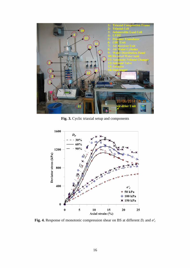
3. Test apparatus and testing programme
The experimental investigations were conducted using an automated pneumatic controlled
CT testing apparatus (Fig. 3). The apparatus consists of a 100 kN capacity loading frame
fitted with a pneumatic dynamic actuator having a double amplitude displacement of 30 mm
(±15 mm) and operational frequency range of 0.01-10 Hz. The system comprises of a triaxial
cell having a maximum confining capacity of 2000 kPa, and an air compressor with a
maximum capacity of 800 kPa. The instrumentations available with the apparatus are: two
linear variable differential transducers, one each for cyclic and static measurements, having a
measuring range of ±15 mm and up to 50 mm respectively; one submersible load cell of
capacity 25 kN; three pressure transducers of capacity 1000 kPa to measure cell pressure,
back pressure and pore-water pressure; and, one automatic volume change measuring device.
The testing was controlled by a compact dynamic controller unit, which conveys the
instructions provided by the DYNATRIAX software and also records the data with the help
of a data logger.
All the tests were conducted on the remoulded cylindrical soil specimens of dimensions 70
mm diameter and 140 mm height [30]. Different specimen preparation techniques were
reported in literature, namely dry pluviation, moist tamping and water sedimentation [30, 31].
For the present investigation, dry pluviation technique was adopted. Each of the specimens
were prepared in three layers. Dry sand was poured through a cone shaped funnel into the
specimen-forming mould. A vacuum pressure of 15-20 kPa was applied before removing the
mould to maintain the verticality of the specimen. Subsequently, the triaxial cell was
mounted on the base plate and then filled with water, followed by simultaneous application of
cell pressure (15-20 kPa) and release of vacuum pressure [31].
The specimen preparation was followed by subsequent saturation and consolidation stages.
In order to expedite the saturation process, the specimen was flushed with CO2 for 10-15
minutes at a pressure lower than 15-20 kPa, the initial cell pressure [31]. Subsequently, de-
aired water was passed through the CO2 flushed specimen. To attain the saturation, the cell
pressure (CP) and back pressure (BP) were then gradually increased in stages while
maintaining an almost constant differential pressure of 10 kPa. After each increment of CP,
the Skempton pore-pressure parameter (B) was estimated to check the saturation status. The
Page 4
4
specimen was considered to be completely saturated when the B-value was obtained to be
greater than 0.95. After attaining the saturation, the specimen was isotropically consolidated
to a targeted σʹc by increasing the CP, while maintaining a constant BP. The consolidated
specimens were then subjected to monotonic and cyclic loading.
Monotonic and cyclic tests were performed on the soil specimens prepared at different Dr
(30, 60 and 90%) and consolidated to varying σʹc (50, 100 and 150 kPa). Undrained
monotonic tests were conducted at a constant axial displacement rate of 1.2 mm/min, the
details of which are enlisted in Table 2. Strain-controlled CT tests were conducted on
isotropically consolidated reconstituted specimens subjected to sinusoidal waveform (f = 1
Hz) and various testing conditions, as presented in Table 3.
4. Test results and discussions
4.1. Undrained monotonic shear
Stress-strain responses of saturated BS specimens obtained from monotonic tests at
different σʹc and Dr are presented in Fig. 4. It is observed that the peak deviator stresses and
the associated strain levels are significantly affected by the variation of σʹc and Dr. At any
given σʹc, the increase in peak deviator stress is substantial (~ 60%) for the increase in Dr
from 30% to 60%, whereas it is marginal (~ 8%) for an increase in Dr from 60% to 90%.
Hence, it can be stated that the effect of variation of σʹc is more prominent for sands with low
Dr, i.e. in the range of loose-to-medium dense sands.
4.2. Undrained cyclic shear
Strain-controlled CT tests were performed on the consolidated specimens. Each test
specimen was subjected to 40 cycles of sinusoidal strain-controlled loading [30].
Corresponding to peak axial strain of 0.20% applied at f = 1 Hz (Fig. 5a) on a soil specimen
prepared at σʹc = 100 kPa and Dr = 30%, Fig. 5(b-d) exhibits the response obtained. Figure 5b
represents the exponential decay of deviator stress with increasing N which can be attributed
to the deformation of soil specimen. The increase in excess pore water pressure (PWP)
generation is portrayed in Fig. 5c, which indicates the gradual increase of excess PWP ratio
(ru) to 1 (i.e. excess PWP = σʹc) during the cyclic loading. As presented in Fig. 5d, the
variation of deviator stress with axial strain (hysteresis loops) depicts the degradation of
damping ratio and shear stiffness of soil with increasing number of loading cycles (N).
During an undrained cyclic loading, the rise of PWP in saturated sand causes the reduction of
inter-granular forces resulting in the decrease of effective stress and soil stiffness [9, 32].
Page 5
5
Similar results have been obtained from different cyclic tests conducted at varying levels of
peak axial strain (), which have been subsequently used to evaluate the dynamic properties
of the soils.
4.3. Evaluation of dynamic properties
Out of all the loading cycles applied during the experimental investigation, dynamic
properties of soil can be mathematically evaluated by considering any one particular
hysteresis loop obtained from a specific loading cycle. Literature indicate the use of different
loading cycles to compute the dynamic soil properties, e.g. 10th
cycle [12], 5th
cycle [14], 3rd
cycle [33] and 1st cycle [19, 34-37]. Matasovic and Vucetic [32] have used separately the 1
st
cycle to calculate the shear modulus and 2nd
cycle to compute damping ratio. The selection of
the hysteresis loop was guided by the assumption that up to the nth
cycle, the hysteresis loop
remained symmetrical.
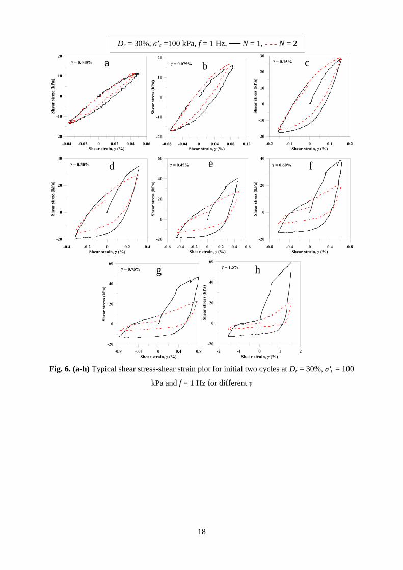
Figure 6 presents the hysteresis loops for initial two cycles, from the strain-controlled CT
tests conducted at different peak shear strain levels. It is seen that the hysteresis loops
becomes gradually asymmetric with increasing peak shear strain. Beyond γ = 0.15%, even the
1st cycle hysteresis loop is observed to be asymmetric (Fig. 6d-h). For the present study, the
1st cycle of loading and the corresponding hysteresis loop has been chosen for the evaluation
of dynamic properties. Figure 7a represents a typical Symmetrical Hysteresis Loop (SHL),
and along with portrays the suggested conventional method of calculation of dynamic
properties [30]. In this method, the dynamic shear modulus (G) is evaluated from secant
Young’s modulus (Esec), obtained by the slope of the line joining the points of peak
compressive and tensile stress-strain points; the damping ratio is evaluated from the stored
strain energy by the triangle in the first quadrant (considering symmetricity for the entire
loading cycle). However, in the case of Asymmetrical Hysteresis Loop (ASHL) as shown in
Fig. 6(d-h), this method will not yield appropriate values as it will lead to the underestimation
of damping ratio due to the consideration of higher strain energy for the entire loop. To take
into the effect of actual strain energy and moduli values in compression and tension, true
representation of asymmetric nature of hysteresis loop should be considered. In that case,
dynamic soil properties are to be evaluated as described in Fig. 7b, which is a regenerated
version of the original methodology stated by Kokusho [12]. Therefore, for an ASHL, a
modified method has been adopted to evaluate the shear modulus (Ga) and damping ratio
(D#). Nevertheless, the conventional method, as stated for a SHL, has also been used to
Page 6
6
evaluate the shear modulus (G) and damping ratio (D), and the same are compared against
those obtained from ASHL for the sake of understanding the necessity of adopting the
modified methodology.
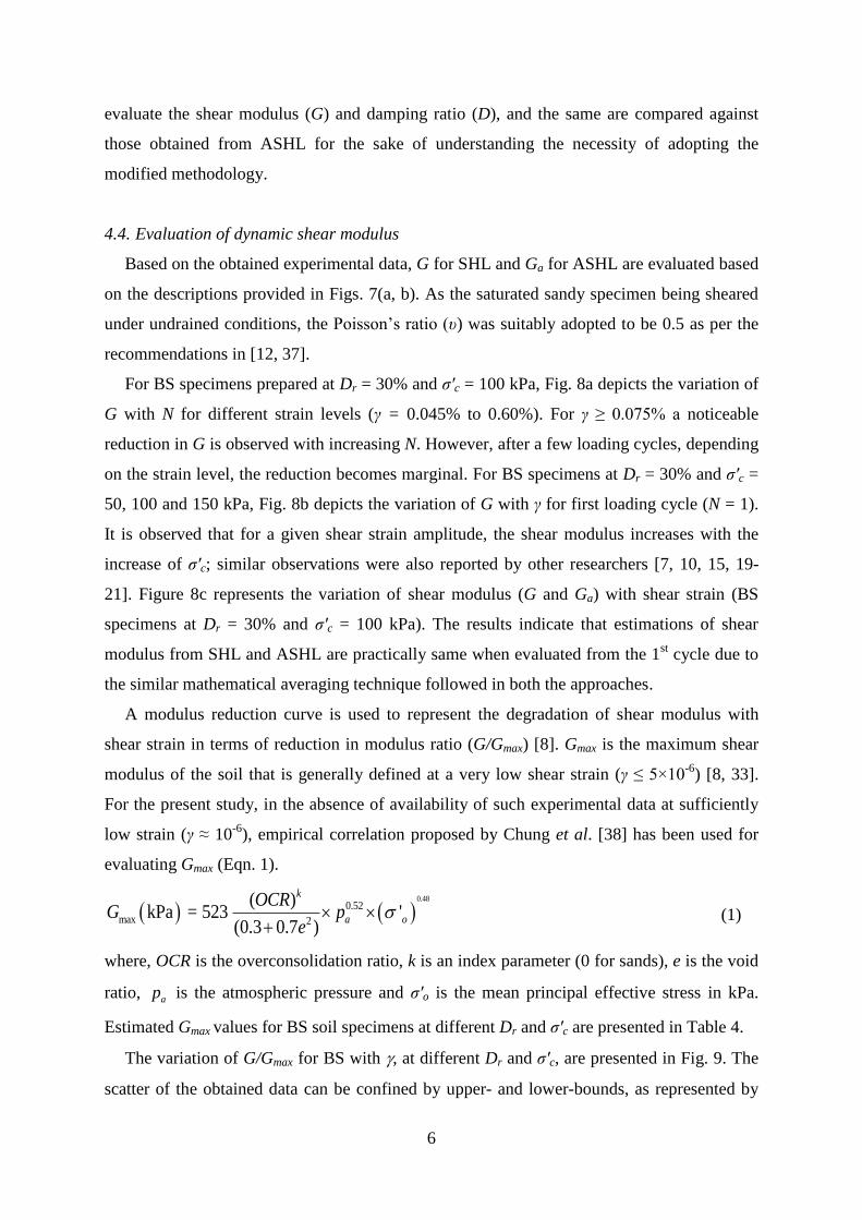
4.4. Evaluation of dynamic shear modulus
Based on the obtained experimental data, G for SHL and Ga for ASHL are evaluated based
on the descriptions provided in Figs. 7(a, b). As the saturated sandy specimen being sheared
under undrained conditions, the Poisson’s ratio (υ) was suitably adopted to be 0.5 as per the
recommendations in [12, 37].
For BS specimens prepared at Dr = 30% and σʹc = 100 kPa, Fig. 8a depicts the variation of
G with N for different strain levels (γ = 0.045% to 0.60%). For γ ≥ 0.075% a noticeable
reduction in G is observed with increasing N. However, after a few loading cycles, depending
on the strain level, the reduction becomes marginal. For BS specimens at Dr = 30% and σʹc =
50, 100 and 150 kPa, Fig. 8b depicts the variation of G with γ for first loading cycle (N = 1).
It is observed that for a given shear strain amplitude, the shear modulus increases with the
increase of σʹc; similar observations were also reported by other researchers [7, 10, 15, 19-
21]. Figure 8c represents the variation of shear modulus (G and Ga) with shear strain (BS
specimens at Dr = 30% and σʹc = 100 kPa). The results indicate that estimations of shear
modulus from SHL and ASHL are practically same when evaluated from the 1st cycle due to
the similar mathematical averaging technique followed in both the approaches.
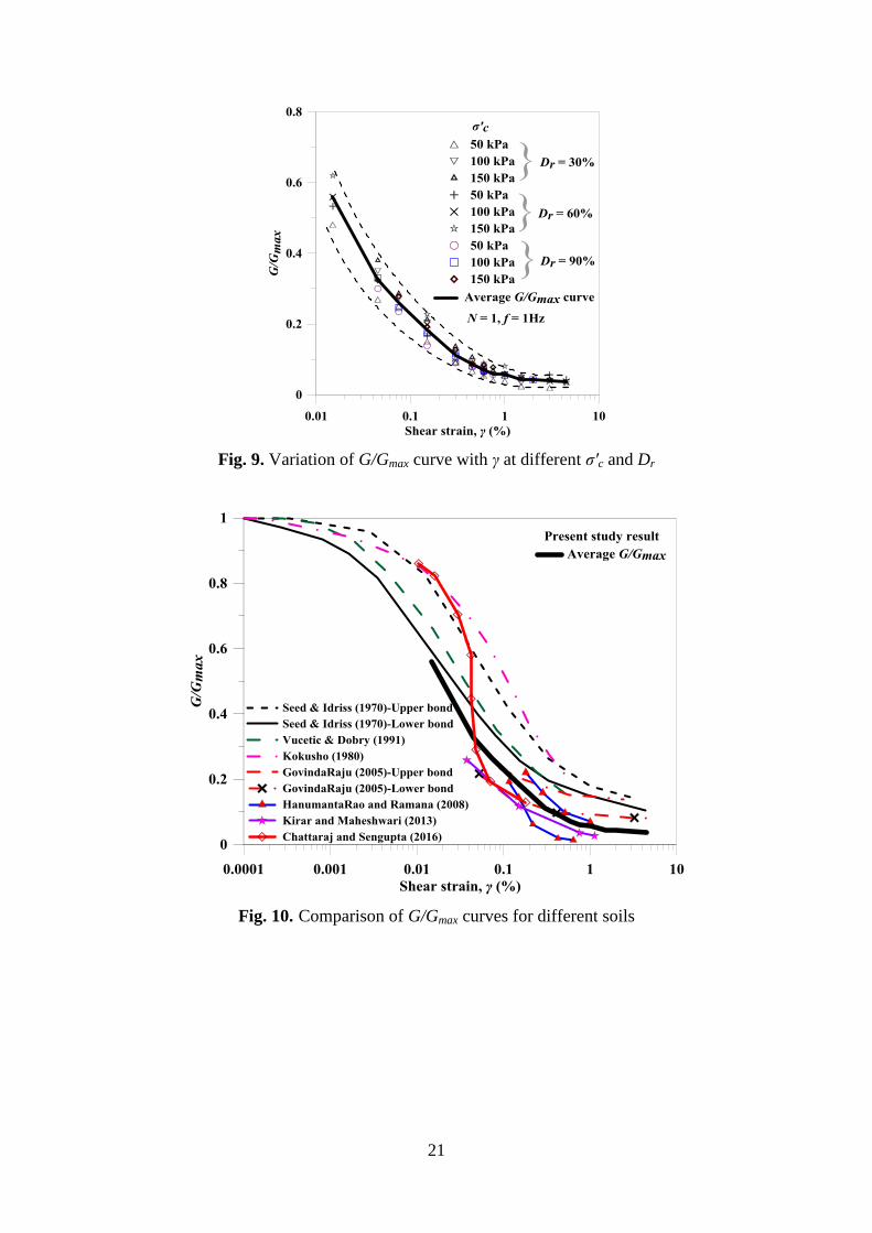
A modulus reduction curve is used to represent the degradation of shear modulus with
shear strain in terms of reduction in modulus ratio (G/Gmax) [8]. Gmax is the maximum shear
modulus of the soil that is generally defined at a very low shear strain (γ ≤ 5×10⁻⁶
) [8, 33].
For the present study, in the absence of availability of such experimental data at sufficiently
low strain (γ ≈ 10-6
), empirical correlation proposed by Chung et al. [38] has been used for
evaluating Gmax (Eqn. 1).
0.48
0.52
max 2
( )kPa = 523 '
(0.3 0.7 )
k
a o
OCRG p
e
(1)
where, OCR is the overconsolidation ratio, k is an index parameter (0 for sands), e is the void
ratio, ap is the atmospheric pressure and σʹo is the mean principal effective stress in kPa.
Estimated Gmax values for BS soil specimens at different Dr and σʹc are presented in Table 4.
The variation of G/Gmax for BS with , at different Dr and σʹc, are presented in Fig. 9. The
scatter of the obtained data can be confined by upper- and lower-bounds, as represented by
Page 7
7
dotted lines in the figure. It can be observed that, at higher strain levels, the scatter of G/Gmax
gets significantly narrowed. For all practical purposes, the obtained estimates can be
represented by an average G/Gmax curve (Fig. 9). The obtained average G/Gmax curve for BS
has been compared with the G/Gmax curves, for different sandy soils, available in the literature
(Fig. 10). In spite of a similar trend, the G/Gmax estimates of BS show lower values in
comparison to the classical curves [10, 12, 16]; although, it is in close agreement to those
reported for Indian soils [19-21]. As each of the established modulus reduction models are
developed based on the dynamic testing of a specific soil [10, 12, 16], adoption of any
particular model to determine the dynamic response of different other soils might be
incorrect. It should be customary that the dynamic properties of each soil be judiciously
determined before its application for any practical geotechnical engineering problems.
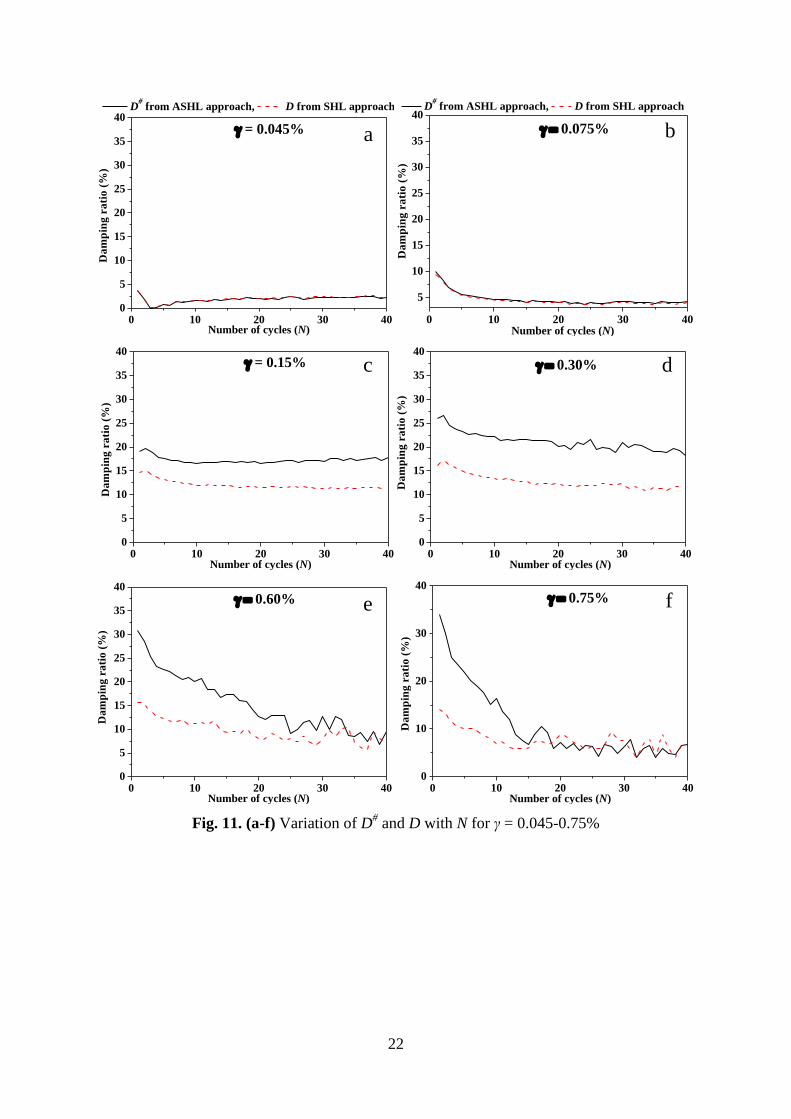
4.5. Evaluation of damping ratio
Figure 11 illustrates the variations of damping ratio with N, computed using both
conventional (D) and the modified method (D#) (as shown in Figs. 7 a, b). For the evaluation
of D#, the stored strain energy in one complete cycle has been considered (represented by the
hatched polygon in Fig. 7b), which comprises of two triangles and a rectangle having the area
AΔ1, AΔ2 and A□ respectively. AL is the area enclosed by the hysteresis loop and is expressed in
Eqn. (2) [39], where i and σi are respectively the axial strain and deviator stress (i = 1 to n,
where n is number of points used to construct the hysteresis loop).
1 2 2 1 2 3 3 2 1 1
1( ) ( ) .... ( )
2L n nA (2)
It is observed that for γ ≤ 0.075%, the differences between D and D# are insignificant,
which is primarily attributed to the nearly symmetrical loop (SHL) at these low shear strains
for all loading cycles. Significant difference is noted between D and D#, at γ ≥ 0.15%, where
D# is found to be noticeably higher than D, due to enhanced asymmetricity of the hysteresis
loops at these strain levels (Fig. 6). This observation inadvertently indicates that the
estimation of damping ratio following conventional method may underestimate the actual
value of damping, and therefore, the modified method should be adopted. For a typical
variation of damping ratio (γ = 0.60%, Fig. 11e), it can be observed that the estimated values
of D and D# become closer, thus suggesting formation of near-symmetrical loops
approximately beyond 30th
cycle. Similar observations are made for the damping ratios
obtained for other peak shear strains (γ > 0.60%, Fig. 11f).
Page 8
8
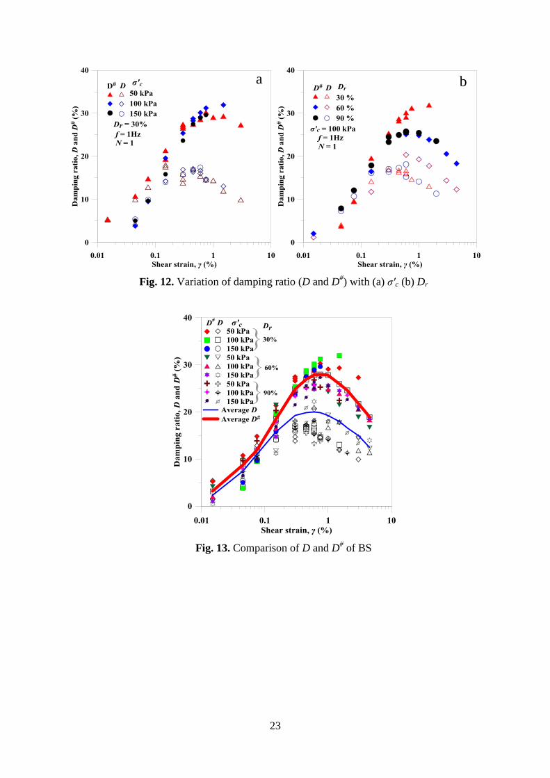
Figures 12- 14 depict the variations of damping ratio (D and D#) with shear strain for test
specimens prepared at different Dr and σʹc. Figure 12a shows the effect of σʹc on D and D#
for
BS specimens at Dr = 30%. It is observed that specimens subjected to lower σʹc (50 kPa)
depicts higher damping ratio in comparison to that obtained at higher σʹc (100 and 150 kPa),
which is attributed to the relatively higher stiffness imparted in the specimens due to higher
confinement. The damping ratio is not found to vary noticeably for σʹc greater than 100 kPa.
It can also be noted that D attains a peak magnitude at a γ = 0.5%, while D# attains the peak
magnitude at γ ≈ 1% (Fig. 12a). Beyond the stated peak values, a significant reduction in
damping ratio is observed at higher strain levels which are noticeably different from that
observed in the damping ratio curves from earlier studies [10-21]. It should be noted that, for
the earlier studies, tests were conducted up to strain levels of about 1%. Very few researchers
have provided the experimental evidence of estimated damping ratio beyond 1% shear strain
[2, 22-23, 32] which followed a similar trend as obtained in the present study. Figure 12b
portrays that up to γ ≈ 0.5%, Dr has an insignificant effect on D and D#
estimated for BS
specimens subjected to σʹc = 100 kPa.
For all practical purposes, Fig. 13 presents the average trends of the estimated D and D#
for BS specimens prepared at different Dr and σʹc. It is observed that, the average trend of D#
exceeds D by 40-70%, with higher deviation at higher strain levels beyond 0.50%. From the
overall observations of Figs. 12-13, it can be stated that the modified method to estimate
damping ratio is significantly important and that conventional method largely underestimates
the actual damping developed in the specimen, especially at higher strain levels.
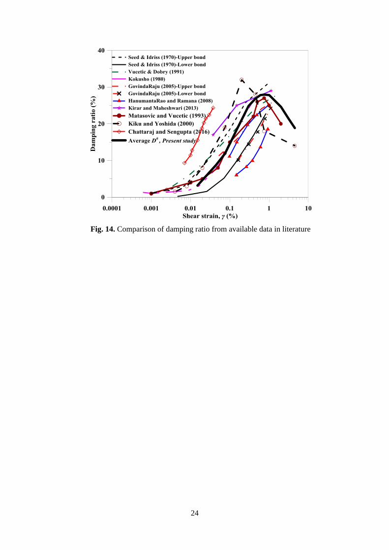
Most of the existing literature reported the estimated damping ratio for γ ≤ 1%, and the
same is extrapolated to estimate the damping ratio for beyond 1% (such as in the existing
commercial software for ground response analyses or any other seismic studies). However,
the present study unambiguously reflects that the damping ratio exhibits non-conventional
behavior γ ≥ 1%, where a noticeably decreasing trend is observed rather than the
conventionally assumed increasing or asymptotic variation. Hence, the current observation
provides a better phenomenological understanding and a scope of improvement of the
existing methods utilizing damping ratio curves beyond γ = 1% by defining a curvilinear
variation for the entire strain range used for the present study. The obtained variation of
damping ratio from the present study has been compared with several data available in
literature as shown in Fig. 14. It can be observed that most of the earlier researchers have
restricted the data up to γ = 1%. The results from the present study also follows the observed
trend (within 1%). Based on the present observation related to the variation of damping ratio
Page 9
9
over the entire strain range, it can be stated that it is not judicious to extrapolate the trend of
damping ratios for γ ≤ 1% to obtain the same for γ >1%. Thus, it is suggested that a new
functional variation of damping ratio should be developed in order to use the same for
various geotechnical engineering purposes involving wider range of shear strain.
5. Conclusions
Strain controlled cyclic triaxial tests have been conducted on saturated Brahmaputra sand
to evaluate the dynamic properties over a wide range of shear strain. Hysteresis loops at
different loading cycles manifested the dynamic behavior of the soil and exhibited noticeable
asymmetric nature, especially at higher strain levels. Since conventional methods do not
account for such asymmetry in the estimation of the dynamic properties of the soil, a
modified method of the evaluation of the same was adopted and has been reported in the
article.
Shear modulus (G) of BS soil is observed to be significantly affected by the variations in
σʹc and Dr. However, the scatter of the estimate becomes lower when expressed in terms of
the modulus reduction (G/Gmax) curve. In comparison to the classical curves, G/Gmax curve of
BS specimens depicted lower range of modulus ratio; however, the trend was well-matching
with those reported for Indian soils. It can be concluded that the direct application of the
existing modulus reduction models may lead to improper estimation of the dynamic response
of any other soil, and hence, a proper characterization of the soil is extremely necessary.
In comparison to higher σʹc, it was observed that BS specimens subjected to lower σʹc
revealed higher damping ratio due to the higher shear stiffness imparted in the specimens by
higher confinement. It is observed that, on an average D# exceeds D by 40-70%, with higher
deviation exhibited at higher strain levels beyond 0.50%. The obtained variation of damping
ratio, from the present study, has been compared with several data available in literature. A
prominent decrease in damping ratio is noted beyond γ = 1%, portraying a marked difference
from the conventional extrapolated estimates. This decrement clearly manifests that the
conventional trends of damping ratio at higher shear strains will result in the adoption of
significantly different magnitudes leading to an improper geotechnical analysis. Hence, it is
imperative to develop and adopt a judicious functional variation of the damping ratio over a
wider strain range for practical purposes.
Page 10
10
References
[1] Suetomi I, Yoshida N. Nonlinear behavior of surface deposit during the 1995 Hyogoken-
Nambu earthquake. Soils and Foundations 1998; 38: 11–22.
[2] Kiku H, Yoshida N. Dynamic deformation property tests at large strains. 12th World
Conference on Earthquake Engineering. New Zealand; 2000. Paper no. 1748.
[3] Kumar SS, Krishna AM. Seismic ground response analysis of some typical sites of
Guwahati City. International Journal of Geotechnical Earthquake Engineering 2013; 4:
83–101.
[4] Hsiao DH, Phan VT. Evaluation of static and dynamic properties of sand–fines mixtures
through the state and equivalent state parameters. Soil Dynamics and Earthquake
Engineering 2016; 84:134-44.
[5] Sağlam S, Bakır BS. Cyclic response of saturated silts. Soil Dynamics and Earthquake
Engineering. 2014; 61: 164-75.
[6] Ishihara K. Soil Behaviour in Earthquake Geotechnics. Oxford science publications;
1996.
[7] Hardin BO, Drnevich VP. Shear modulus and damping in soils: measurement and
parameter effects. Journal of Soil Mechanics and Foundations Division 1972; 6: 603–24.
[8] Kramer SL. Geotechnical earthquake engineering. Prentice Hall; New Jersey (NJ): 1996.
[9] Seed HB, Lee KL. Liquefaction of saturated sands during cyclic loading. Journal of the
Soil Mechanics and Foundations Division 1966; 92: 105–34.
[10] Seed HB, Idriss IM. Soil moduli and damping factors for dynamic response analyses.
Report No. EERC 70–10, Earthquake Engineering Research Centre, University of
California, Berkeley, California; 1970.
[11] Iwasaki T, Tatsuoka F, Takagi Y. Shear modulus of sands under torsional shear loading.
Soils and Foundations 1978; 18: 39–56.
[12] Kokusho T. Cyclic triaxial test of dynamic soil properties for wide strain range. Soils and
Foundations 1980; 20: 45–60.
[13] Kokusho T, Yoshida Y, Esashi Y. Dynamic properties of soft clay for wide strain range.
Soils and Foundations 1982; 22: 1–18.
[14] Seed HB, Wong RT, Idriss IM, Tokimatsu K. Moduli and damping factors for dynamic
analysis of cohesionless soils. Journal of Geotechnical Engineering 1986; 112(11):
1016–32.
[15] Chattaraj R, Sengupta A. Liquefaction potential and strain dependent dynamic properties
of Kasai River sand. Soil Dynamics and Earthquake Engineering 2016; 90: 467–475.
Page 11
11
[16] Vucetic M, Dobry R. Effect of soil plasticity on cyclic response. Journal of Geotechnical
Engineering 1991; 117: 89–107.
[17] Ishibashi I, Zhang X. Unified dynamic shear moduli and damping ratios of sand and
clay. Soils and Foundations 1993; 33: 182–91.
[18] Sas W, Gabryś K, Szymański A. Experimental studies of dynamic properties of
Quaternary clayey soils. Soil Dynamics and Earthquake Engineering 2017; 95: 29-39.
[19] Govindaraju L. Liquefaction and dynamic properties of sandy soils. (PhD thesis). Indian
Institute of Science Bangalore, India; 2005.
[20] Hanumantharao C, Ramana GV. Dynamic soil properties for microzonation of Delhi,
India. Journal of Earth System and Science 2008; 117: 719–30.
[21] Kirar B, Maheshwari BK. Effects of silt content on dynamic properties of Solani sand.
Proceeding of 7th International Conferences on Case Histories in Geotechnical
Engineering. Chicago; 2013.
[22] Brennan AJ, Thusyanthan NI, Madabhushi SPG. Evaluation of shear modulus and
damping in dynamic centrifuge tests. Journal of Geotechnical and Geoenvironmental
Engineering 2005; 131: 1488–97.
[23] Mashiri MS. Monotonic and cyclic behaviour of sand-tyre chip (STCh) mixtures. (PhD
thesis). School of Civil, Mining and Environmental Engineering. University of
Wallongong, Australia; 2014. p 290.
[24] IS: 2720 (Part-4). Grain size analysis. Bureau of Indian Standards, New Delhi 1975.
[25] ASTM D2487. Standard practice for classification of soils for engineering purposes
(Unified soil classification system). ASTM International, West Conshohocken, PA;
2006.
[26] IS: 1498. Classification and Identification of soils for general engineering purposes.
Bureau of Indian Standards, New Delhi 1970.
[27] Xenaki VC, Athanasopoulos GA. Liquefaction resistance of sand-mixtures: An
experimental investigation of the effect of fines. Soil Dynamics and Earthquake
Engineering 2003; 183–94.
[28] IS: 2720 (Part-3). Determination of specific gravity-fine, medium and coarse grained
soils. Bureau of Indian Standards, New Delhi 1981.
[29] IS: 2720 (Part-14). Determination of density index of cohesionless soils. Bureau of
Indian Standards, New Delhi 1983.
Page 12
12
[30] ASTM D3999. Standard test methods for the determination of the modulus and damping
properties of soils using the cyclic triaxial apparatus. ASTM International, West
Conshohocken, PA; 2011.
[31] Ishihara K. Liquefaction and flow failure during earthquakes. Geotechnique 1993; 43(3):
351–415.
[32] Matasovic N, Vucetic M. Cyclic characterization of liquefiable sands. Journal of
Geotechnical and Geoenvironmental Engineering 1993; 119: 1805–22.
[33] Okur DV, Ansal A. Stiffness degradation of natural fine grained soils during cyclic
loading. Soil Dynamics and Earthquake Engineering 2007; 27: 843–54.
[34] Lanzo G, Vucetic M, Doroudian M. Reduction of shear modulus at small strains in
simple shear. Journal of Geotechnical and Environmental Engineering 1997; 123: 1035–
42.
[35] Vucetic M, Lanzo G, Doroudian M. Damping at small strain in cyclic simple shear test.
Journal of Geotechnical and Geoenvironmental Engineering 1998; 124: 585–95.
[36] Vucetic M, Mortezaie A. Cyclic secant shear modulus versus pore water pressure in
sands at small cyclic strains. Soil Dynamics and Earthquake Engineering 2015; 70: 60-
72.
[37] Rollins KM, Evans MD, Diehl NB, Daily WD. Shear modulus and damping ratio for
gravels. Journal of Geotechnical and Geoenvironmental Engineering 1998; 124: 396–
405.
[38] Chung RM, Yokel FY, Drnevich VP. Evaluation of dynamic properties of sands by
resonant column testing. Geotechnical Testing Journal 1984; 7: 60–9.
[39] Kreyszig E. Advanced Engineering Mathematics. John Wiley & Sons; US: 2010.
Page 13
13
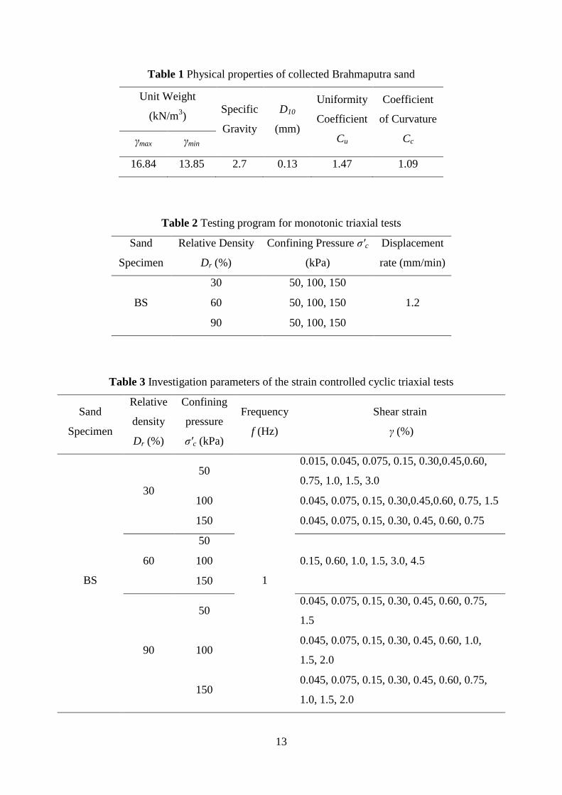
Table 1 Physical properties of collected Brahmaputra sand
Unit Weight
(kN/m3)
Specific
Gravity
D10
(mm)
Uniformity
Coefficient
Cu
Coefficient
of Curvature
Cc γmax γmin
16.84 13.85 2.7 0.13 1.47 1.09
Table 2 Testing program for monotonic triaxial tests
Sand
Specimen
Relative Density
Dr (%)
Confining Pressure σʹc
(kPa)
Displacement
rate (mm/min)
BS
30 50, 100, 150
1.2 60 50, 100, 150
90 50, 100, 150
Table 3 Investigation parameters of the strain controlled cyclic triaxial tests
Sand
Specimen
Relative
density
Dr (%)
Confining
pressure
σʹc (kPa)
Frequency
f (Hz)
Shear strain
γ (%)
BS
30
50
1
0.015, 0.045, 0.075, 0.15, 0.30,0.45,0.60,
0.75, 1.0, 1.5, 3.0
100 0.045, 0.075, 0.15, 0.30,0.45,0.60, 0.75, 1.5
150 0.045, 0.075, 0.15, 0.30, 0.45, 0.60, 0.75
60
50
0.15, 0.60, 1.0, 1.5, 3.0, 4.5 100
150
90
50 0.045, 0.075, 0.15, 0.30, 0.45, 0.60, 0.75,
1.5
100 0.045, 0.075, 0.15, 0.30, 0.45, 0.60, 1.0,
1.5, 2.0
150 0.045, 0.075, 0.15, 0.30, 0.45, 0.60, 0.75,
1.0, 1.5, 2.0
Page 14
14
Table 4 Estimated Gmax for BS
σʹc (kPa) 50 100 150
Dr (%) Gmax (MPa)
30 49.64 69.24 84.12
60 57.73 80.52 97.82
90 67.25 84.12 113.95
Page 15
15
Fig. 1. FESEM image of Brahmaputra Sand (BS)
1E-4 1E-3 0.01 0.1 1 10
0
20
40
60
80
100
Percen
tag
e f
iner
Praticle size (mm)
Boundaries for
partial liquefiable zone
Boundaries for
severely liquefiable zone
Brahmaputra sand (BS)
Fig. 2. Particle size distribution of BS
Page 16
16
Fig. 3. Cyclic triaxial setup and components
Fig. 4. Response of monotonic compression shear on BS at different Dr and σʹc
Page 17
17
Fig. 5. Typical test result plots at ε = 0.20%, f = 1 Hz, σʹc = 100 kPa and Dr = 30% (a) Axial
strain vs N (b) Deviator stress vs N (c) PWP ratio vs N (d) Stress vs strain
a
c d
b
Page 18
18
Fig. 6. (a-h) Typical shear stress-shear strain plot for initial two cycles at Dr = 30%, σʹc = 100
kPa and f = 1 Hz for different γ
a b c
d e f
g h
Dr = 30%, σ'c =100 kPa, f = 1 Hz, ── N = 1, ˗ ˗ ˗ N = 2
Page 19
19
Fig. 7. A typical (a) SHL (Redrawn after Kramer, 1996) and (b) ASHL
1.
1
4LA
AD
AΔ
AL
Axial
strain (ε)
Deviator
stress (σd)
εmax
εmin
σd,max
σd,min
Emax 1
Esec 1
(a)
1.
Axial
strain (ε)
Deviator
stress (σd)
εmax
εmin
σd,max
σd,min
Emax
1 Esec1
1
Esec2 1
Loading Curve
Unloading Curve
a
c
d
ef
g
AΔ1
bAL
o
AΔ2 A
(b)
sec
sec
,max ,min
max min
/
/[2(1 )]
(1 )
1
4
d d
d
L
E
G E
AD
A
sec1 sec2sec,
sec,
( )#
1 2
2
/[2(1 )]
(1 )
1
a
a a
L o a b c d
E EE
G E
AD
A A A
Page 20
20
Fig. 8. Variation of shear modulus with (a) N (b) σʹc (c) SHL and ASHL
a b
c
Page 21
21
Fig. 9. Variation of G/Gmax curve with γ at different σʹc and Dr
Fig. 10. Comparison of G/Gmax curves for different soils
Page 22
22
0 10 20 30 400
5
10
15
20
25
30
35
40 D
# from ASHL approach, D from SHL approach
D
am
pin
g r
ati
o (
%)
Number of cycles (N)
= 0.045%
0 10 20 30 40
5
10
15
20
25
30
35
40
Number of cycles (N)
D
am
pin
g r
ati
o (
%)
D# from ASHL approach, D from SHL approach
0.075%
0 10 20 30 400
5
10
15
20
25
30
35
40 = 0.15%
Da
mp
ing
ra
tio
(%
)
Number of cycles (N)0 10 20 30 40
0
5
10
15
20
25
30
35
40
D
am
pin
g r
ati
o (
%)
0.30%
Number of cycles (N)
0 10 20 30 400
5
10
15
20
25
30
35
40
0.60%
Da
mp
ing
ra
tio
(%
)
Number of cycles (N) 0 10 20 30 40
0
10
20
30
40
0.75%
Da
mp
ing
ra
tio
(%
)
Number of cycles (N)
Fig. 11. (a-f) Variation of D# and D with N for γ = 0.045-0.75%
a b
c d
e f
Page 23
23
Fig. 12. Variation of damping ratio (D and D#) with (a) σʹc (b) Dr
Fig. 13. Comparison of D and D# of BS
a b
Page 24
24
Fig. 14. Comparison of damping ratio from available data in literature