Journal of Petroleum Research & Studies NO.5 - 2012 E 131 Evaluation of Mixed Corrosion Inhibitors in Cooling Water System Dina Raheem Collage of Electronic and Electrical Technique Abstract: The effect of mixed corrosion inhibitors in cooling system was evaluated by using carbon steel specimens and weight loss analysis. The carbon steel specimens which immersed in mixture of sodium phosphate ( Na 2 HPO 4 ) used as corrosion inhibitor and sodium glocunate ( C 6 H 11 NaO 7 ) as scale dispersant at different concentrations (20,40, 60, 80 ppm) and at temperature 25°C for (1-5) days. The corrosion inhibitors efficiency was calculated by using uninhibited and inhibited water to give 98.1%. The result of these investigation indicate that the corrosion rate decrease with increase the corrosion inhibitors concentration at 80 ppm and for 5 days, (i.e. corrosion rate= 0.042 gmd). Keyword: carbon steel corrosion, corrosion in cooling tower, corrosion inhibitors in cooling tower. صة : الخ تظوسة ستآكل يبظ س خ ت سؼاتؼتبل يةطلل اتو كلو يي. ل اتوكلذج ي نل غوموم يواسظ س خNa 2 HPO 4 ومومه يوككبظ تعكل كC 6 H 11 NaO 7 ةت ستليك تكةته ك( 20,40,60,80 ) ػوءيللة مل25 ◦ م( 1-5 ) م ا. ب تب يء كسغ ةضءيم ساتظ يءنه ككض ي98.1% ػ تلك80 وء. س ابحر تب يئ نتبظظ س خ تلكمل سغتآكل ي سؼ تلكتآكل ػ ي80 وء5 م ا, تآكل ي سؼ ة ا0.042 غ/ م2 . وم.
Transcript
Journal of Petroleum Research & Studies NO.5 - 2012
E 131
Evaluation of Mixed Corrosion Inhibitors
in Cooling Water System
Dina Raheem
Collage of Electronic and Electrical Technique
Abstract:
The effect of mixed corrosion
inhibitors in cooling system was
evaluated by using carbon steel
specimens and weight loss analysis.
The carbon steel specimens which
immersed in mixture of sodium
phosphate ( Na2HPO4 ) used as
corrosion inhibitor and sodium
glocunate ( C6 H11 NaO7 ) as scale
dispersant at different concentrations
(20,40, 60, 80 ppm) and at
temperature 25°C for (1-5) days. The
corrosion inhibitors efficiency was
calculated by using uninhibited and
inhibited water to give 98.1%. The
result of these investigation indicate
that the corrosion rate decrease with
increase the corrosion inhibitors
concentration at 80 ppm and for 5
days, (i.e. corrosion rate= 0.042
gmd).
Keyword: carbon steel corrosion, corrosion in cooling tower, corrosion
inhibitors in cooling tower.
الخلاصة :
ت ََ خ َظ س ب ي تآكل ٌ س ظوسة ت
كل و اتَل طلٍ ة ي تبلٍ اتؼ سؼ
غ ل ن ذج ي كل و اتَل ٌ . ي ي و
Na2HPO4خ َظ سس وا ي ومٍوم
C6H11NaO7ك بظ تعكل ك وك َه ي ومٍوم
ك ةته تك تليكَ س ت ة
ء َو ػ ( 20,40,60,80)
ت ب . اٍ م (5-1)م ◦25مل ة ليل
ات يم س ء ةض سغ ك ء ي ب
ػ %98.1يلإض ك نه ك ء ي َظ
نت ئ ي بحر تبَس ا . ء َو 80تلكَ
سؼ ي تآكل ٍ ل سغ ٍ م تلكَ خ َظ س بظ
5 ء َو 80ي تآكل ػ تلكَ
م/غ 0.042اً ة سؼ ي تآكل , اٍ م2 .ٍوم .
Journal of Petroleum Research & Studies
NO.5 - 2012
E 132
Introduction:
The term ―corrosion‖ (in a
cooling water system) is defined as
the electrochemical deterioration of a
metal that is in contact with cooling
water. Corrosion occurs when an
electric current flows from one part
of the metal (anode) through the
water (electrolyte) to another part of
the metal (cathode). Corrosion takes
place at the anode only. The cathode
is the driving force of the corrosion
action, as shown in the equation;
Metal Metal ions + electrons
M Mn+
+ ne ----- (1)
This process degrades the metal,
reduces its strength, thickness, and in
some extreme cases, creates pits and
then holes in the material. At some
point in the corrosion process , the
metal can no longer do its job as a
system component. Corrosion, in
general, and pitting corrosion, in
particular, must be guarded against
in order to ensure the long term
integrity of the cooling system.[1]
In the corrosion of iron the reaction
may proceed by a single step
oxidation Fe into ferric ion:
Fe Fe+3
+ 3e- -------- (2)
In practice, a two-step process
occurs in which iron is first oxidized
to ferrous ion which depending on
the anode potential.
Fe Fe+2
+ 2e- -------- (3)
And then is oxidized into ferric ion
Fe2+
Fe+3
+ e- -------(4)
The reactions above take place at the
anode and must be balanced by other
reduction processes that occur at the
cathode. For example:
O2 (gas) + 4H + 4e- 2H2O ------
(5)
O2 (gas) + H2O + 4e- 4OH- ------
- (6)
The formation of OH- at the cathode
causes the pH here to be higher than
in the bulk solution. Eventually, ion
migration of OH- occurs, towards
the anode, which promotes the
formation of ferric hydroxide:
Journal of Petroleum Research & Studies NO.5 - 2012
E 133
Fe+3
+ 3OH- Fe (OH)3 ------(7)
Fe (OH)3 appears in the form of
reddish brown colloid. This ferric
hydroxide may react further in the
presence of ferrous ions to produce
Fe3O4.[2]
The primary objectives of cooling
water treatment are to maintain the
operating efficiency of the cooling
water system and to protect the
equipment that contacts the cooling
water. These objectives are
accomplished by controlling or
minimizing deposition, corrosion,
and microbiological growth on the
cooling water equipment The
deposits that occur in cooling water
systems are usually divided into two
categories: scale and fouling. The
presence of either type of deposit in
the heat exchangers or in the film fill
can interfere with heat transfer,
thereby reducing the efficiency of
operation. Deposits can also promote
under-deposit corrosion. Scale is
formed from minerals, formerly
dissolved in water, that were
deposited from the water onto heat
transfer surfaces or in-flow water
lines. As water is evaporated in a
cooling tower, the concentration of
dissolved solids becomes greater
until the solubility of a particular
scale-causing mineral salt is
exceeded. When this situation occurs
in an untreated cooling water system,
the scale will form on any surface in
contact with the water, especially on
heat transfer surfaces. The most
common scaling minerals are
calcium carbonate (CaCo3), calcium
phosphate (CaPo4), calcium sulfate
(CaSo4), and silica, usually in that
order. Formation of magnesium
silicate scale is also possible under
certain conditions. Most other salts,
including silica, are more soluble in
hot water than in cold water;
however, most calcium and
magnesium salts, including calcium
phosphate and calcium carbonate,
are more soluble in cold water than
in hot water. This is called ―reverse
solubility.‖ The water temperature
will increase as recirculating water
passes through the cooling system.
As a result, calcium and magnesium
scales may form anywhere in the
Journal of Petroleum Research & Studies
NO.5 - 2012
E 134
system, but most likely on heated
surfaces such as heat exchangers or
surface condensers. Silica will form
in areas having the lowest water
temperature, such as in the cooling
tower fill.
Scale, in addition to causing physical
blockage of piping, equipment, and
the cooling tower, also reduces heat
transfer and increases the energy use.
For example, the thermal
conductivity BTU/ [hr (ft2) (F/in)] of
copper is 2674, while the common
cooling water scale calcium
carbonate has a thermal conductivity
of 6.4 BTU/ [hr (ft2) (F/in)].
A calcium carbonate scale of just 1.5
mil thickness is estimated to
decrease thermal efficiency by 12.5
%. The principle factors responsible
for scale formation are:
1. As alkalinity increases, calcium
carbonate- the most common
scale constituent in cooling
systems - decreases in solubility
and deposits.
2. The second—more significant—
mechanism for scale formation is
the in-situ crystallization of
sparingly soluble salts as the
result of elevated temperatures
and/or low flow velocity. Most
salts become more soluble as
temperature increases, however,
some salts, such as calcium
carbonate, become less soluble as
temperature increases. Therefore
they often cause deposits at
higher temperatures.
3. High TDS water will have greater
potential for scale formation.
The common term used to
describe the water use efficiency
of cooling tower water systems is
COC. COC represents the
relationship between the makeup
water quantity and blow down
quantity. COC is a measure of the
total amount of minerals that is
concentrated in the cooling tower
water relative to the amount of
minerals in the makeup water or
to the volume of each type of
water.
The higher the COC, the greater the
water use efficiency. Most
cooling tower systems operate
Journal of Petroleum Research & Studies NO.5 - 2012
E 135
with a COC of 3 to 10, where 3
represents acceptable efficiency
and 10 represents very good
efficiency. It has been found that
the range of 5 to 7 COC
represents the most cost-effective
situation.[3]
The COC of small, medium,
and large cooling towers may be
controlled by blow down, either
automatic or manual, to avoid the
high levels of silica and calcium salts
that can lead to scale. If the cooling
tower is not chemically treated, the
COC should be adjusted to be
slightly less than the lowest
allowable COC value based on all
scale-forming water ingredients. The
use of chemical treatment permits a
higher COC, which is usually limited
by either the chemical effectiveness
or the water treatment control.[4]
water is used in cooling systems as a
heat transfer medium and frequently
also as the final point to reject heat
into the atmosphere by evaporating
inside cooling towers. Depending on
the quality of available fresh water
supply, waterside problems develop
in cooling water systems from: -
Scaling , - Corrosion ,- Dirt and
dust accumulation , - Biological
growth .
Any of these problems – or more
usually a combination of them –
result in costly unscheduled
downtime, reduced capacity,
increased water usage, high
operation and maintenance costs,
expensive parts replacements, and
acid cleaning operations which
reduce the life of the cooling system.
Selection of water treatment program
for a specific system depends on:
1. System design, including system
capacity, cooling tower type,
basin depth, materials of
construction, flow rates, heat
transfer rates, temperature drop
and associated accessories
2. Water, including makeup water
composition / quality, availability
of pre-treatment and assumed
cycle of concentration
3. Contaminants, including process
leaks and airborne debris
Journal of Petroleum Research & Studies
NO.5 - 2012
E 136
4. Wastewater discharge restrictions
5. Surrounding environment and air
quality
The critical parameters for cooling
water are: conductivity, total
dissolved solids (TDS), hardness,
pH, alkalinity and saturation
index. Conductivity is a measure
of the ability of water to conduct
electrical current and it indicates
the amount of the dissolved solids
(TDS) in water. Pure distilled
water will have a very low
conductivity (low minerals) and
sea water will have a high
conductivity (high minerals).
Dissolved solids showed no
problem with respect to the
cooling capacity of water, since
the evaporation rate of seawater,
which has 30,000ppm total
dissolved solids, is only 1% less
than that of distilled water. The
problem with dissolved solids is
that many of the chemical
compounds and elements in the
water will combine to form
highly insoluble mineral deposits
on the heat transfer surfaces
generally referred to as ―scale‖.
The scale stubbornly sticks to the
surfaces, gradually builds up and
begins to interfere with pipe
drainage, heat transfer and water
pressure.
pH : is a measure of how
acidic/basic water is. The range goes
from 0 - 14, with 7 being neutral.
pHs of less than 7 indicate acidity,
whereas a pH of greater than 7
indicates a base. pH is reported in
"logarithmic units," like the Richter
scale, which measures earthquakes.
Each number represents a 10-fold
change in the acidity/baseness of the
water. Water with a pH of 5 is ten
times more acidic than water having
a pH of six.
In general, when pH points to acidic
environment, the chances for
corrosion increase and when pH
points to alkaline environment, the
chances for scale formation increase.
Alkalinity : The pH values above 7
signify alkalinity. At pH values less
than 8.3, most of the alkalinity in the
Journal of Petroleum Research & Studies NO.5 - 2012
E 137
water is in the bicarbonate form, and
scale formation is normally not a
problem. However, when the pH
rises above 8.3, the alkalinity
converts from the bicarbonate to the
carbonate and the scale will start to
form.
Hardness :The amount of dissolved
calcium and magnesium in water
determines its "hardness." The total
hardness is then broken down into
two categories :a. The carbonate or
temporary hardness b. The non-
carbonate or permanent hardness
Hardness particularly the temporary
hardness is the most common and is
responsible for the deposition of
calcium carbonate scale in pipes and
equipment. Technically any bivalent
metal ion such as iron, manganese or
tin would constitute hardness, but
calcium and magnesium are the two
most prevalent forms.
Saturation Index :The saturation
index of a water or Langlier
Saturation Index (LSI) is a measure
of the stability of the water with
respect to scale formation. When LSI
readings are positive they tend to be
scale forming, and when they are
negative they tend to be corrosive.
Normally readings within 1.0 units
from zero are considered
stable.[5][6]
In cooling water systems, two basic
techniques are used to provide
corrosion protection to the metals
that the water contacts: use of
chemical corrosion inhibitors, and
raising the pH of the cooling water.
Most military cooling water systems
contain components fabricated
primarily of copper alloy and mild
steel. Galvanized steel is present in
galvanized cooling towers and
stainless steel may be present in
piping. As the cooling water pH is
increased (ideally to within the range
of 8.0 to 9.5.
Corrosion inhibitors are chemicals,
which inhibit or reduce the corrosion
rate of the steel or metallic surfaces.
Corrosion is an electrochemical
phenomenon, which occurs due to
anodic and/or cathodic. reactions.
Generally, the anodic reaction is the
metal ion oxidation, and the cathodic
reaction is the hydrogen ion
Journal of Petroleum Research & Studies
NO.5 - 2012
E 138
reduction. Therefore, the corrosion
analysis and the corrosion inhibitors
used to control the anodic reactions
are classified as anodic corrosion
inhibitor and the cathodic reactions
are called as cathodic inhibitors.
Anodic Inhibitors form a protective
film coating on the anodic metal
(where the metal is lost) and thus
directly control corrosion by
preventing the reaction that results in
corrosion. Any unprotected areas
will corrode at a much faster rate
than the protected areas, a factor that
could result in pitting or localized
attack of the unprotected areas.
Cathodic Inhibitors form a
protective film coating of the
cathodic metal (where metal is not
lost) and thus indirectly prevent
corrosion by interfering with the
current flow required for the
electrochemical reaction to proceed
between the cathodic and anodic
metals. The corrosion reaction rate is
governed by the size and type of the
cathode relative to the anode. Even
when cathodic areas are not
completely covered by the protective
film, corrosion will occur, but
usually more slowly and uniformly
than when using anodic inhibitors
alone. The occurrence of localized
corrosion or pitting attack is greatly
reduced.
Industrial Cooling water treatment
contains these two types of
corrosion inhibitors. Anodic
inhibitors are called dangerous
inhibitors. If inhibitor concentration
is low then parts of the anode are
not protected. The unprotected
anode will experience severe
corrosion. corrosion control
methodologies are based on the
electrochemical principles.[6]
Table (1) shows criteria for the
selection of corrosion inhibitors.
The principal strategy for a cooling
system corrosion protection
program is to ensure protection of
the metal in the heat exchanger
(metal that is the thinnest metal in
the system). The secondary goal is
to provide protection from
corrosion of the mild steel piping.
When galvanized steel cooling
towers are part of the cooling
Journal of Petroleum Research & Studies NO.5 - 2012
E 139
system, specialized corrosion
inhibitors are the best control
method. Galvanized steel is
corroded at pH levels above 9.0 and
below 6.0.
Table(1) Criteria for Corrosion Inhibitor Selection
Corrosion Inhibitor
Metal
Steel Copper
Aluminum
pH Range
(ideal)
Cathodic Inhibitor
Polyphosphate Excellent Attacks
Attacks
6.5-8.5
Zinc salts Excellent None
None
6.5-8.5
Polysilicate Excellent Excellent
Excellent
7.5-10.0
Molybdate Good Fair
Fair
7.5-10.0
Anodic Inhibitor
Orthophosphate Good Attacks
Attacks
6.5-8.5
Orthosilicate
Good Good
Good
7.5-10.0
Effective corrosion control requires
maintaining appropriate pH levels,
plus adding maintenance dosages of
chemical corrosion inhibitors.
Chemical corrosion inhibitors form a
protective film or barrier on the
cooling system metal surfaces that
have been cleaned prior to adding an
initial high dosage of inhibitor. The
initial high dosage of inhibitor
passivates (protects) the metal. The
appropriate dosage of corrosion
inhibitor must be maintained
continuously in the cooling water to
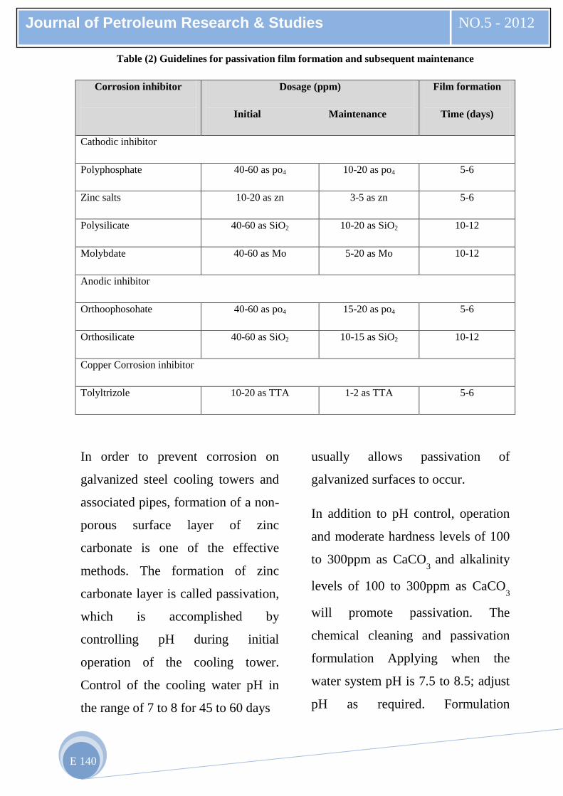
ensure continuing protection. Table
(2 ) shows examples of various
passivation and maintenance dosage
levels of corrosion inhibitors.[7,8]
Journal of Petroleum Research & Studies
NO.5 - 2012
E 140
Table (2) Guidelines for passivation film formation and subsequent maintenance
Corrosion inhibitor
Dosage (ppm)
Initial Maintenance
Film formation
Time (days)
Cathodic inhibitor
Polyphosphate 40-60 as po4 10-20 as po4 5-6
Zinc salts 10-20 as zn 3-5 as zn 5-6
Polysilicate 40-60 as SiO2 10-20 as SiO2 10-12
Molybdate 40-60 as Mo 5-20 as Mo 10-12
Anodic inhibitor
Orthoophosohate 40-60 as po4 15-20 as po4 5-6
Orthosilicate 40-60 as SiO2 10-15 as SiO2 10-12
Copper Corrosion inhibitor
Tolyltrizole 10-20 as TTA 1-2 as TTA 5-6
In order to prevent corrosion on
galvanized steel cooling towers and
associated pipes, formation of a non-
porous surface layer of zinc
carbonate is one of the effective
methods. The formation of zinc
carbonate layer is called passivation,
which is accomplished by
controlling pH during initial
operation of the cooling tower.
Control of the cooling water pH in
the range of 7 to 8 for 45 to 60 days
usually allows passivation of
galvanized surfaces to occur.
In addition to pH control, operation
and moderate hardness levels of 100
to 300ppm as CaCO3
and alkalinity
levels of 100 to 300ppm as CaCO3
will promote passivation. The
chemical cleaning and passivation
formulation Applying when the
water system pH is 7.5 to 8.5; adjust
pH as required. Formulation
Journal of Petroleum Research & Studies NO.5 - 2012
E 141
limitations may require adding
separate components to keep things
in solution. Other formulations may
be used:
*Orthophosphate or hexametapho-
sphate as(PO4) :60 ppm
* Polyacrylate(active) : 20 ppm
* Tolyltrizol (active) : 10 ppm
* Soduim gluconate : 50 ppm
* Pluronic L-61 (active)(non ionic
surfactant with antifoam: 400 ppm
* Phosphate scale inhibitor: 50 ppm
The chemical significations for
corrosion inhibitors may be written
as following:
1. Polymers (Polyacrylate, etc) -
Disperse sludge and distort
crystal structure of calcium
deposits. Prevent fouling due to
corrosion products. Commonly
used, cost effective for calcium
scale at 5 to 15 mg/l.
2. Phosphonates - Phosphonates are
excellent calcium scale inhibitors
at levels from 2 to 20 mg/l.
3. Sodium Phosphates (NaH2PO4,
Na2HPO4, Na3PO4, NaPO3) -
Precipitates calcium as hydr-
oxyapatite (Ca10
(OH)2(PO
4)
6).
Stream pH must be kept high for
this reaction to occur.
4. Sodium Aluminates (NaAl2O4) -
Precipitates calcium and
magnesium.
5. Coploymers - These products
commonly incorporate two active
groups, such as a sulfonate and
acrylate, to provide superior
performance to a single group
compound at use levels at 5 to 20
mg/l, higher cost.
6. Terpolymers - Like the co-
polymers, only incorporate three
active groups to give yet better
performance under severe
conditions at use levels of 5 to 20
mg/l, costly.
7. Polyphosphates - Fairly good
calcium scale control under mild
conditions. Polyphosphates are of
some value for scale control but
must be applied cautiously,
Journal of Petroleum Research & Studies
NO.5 - 2012
E 142
because hydrolysis of the
polyphosphate results in the
formation of orthophosphate ions.
If this process is not properly
controlled, calcium phosphate
deposits may result.
8. Tannins, starches, glucose, and
lignin derivatives - Prevent feed
line deposits by coating scale
crystals to produce sludge that
will not readily adhere to heat
exchanger surfaces.[9]
In general, another types of
corrosion inhibitors are :
Mixed inhibitor : is composes of
two or three types of inhibitors and
majority of the proprietary corrosion
inhibitor formula falls into this
category. Since chemicals with
different characteristics supplement
their deficiency with each other,
efficacy of the mixed inhibitor
increases. Hence, dosage conce-
ntration can be significantly reduced,
thus, lowering the operating cost and
environmental impacts caused by
chemicals.
Adsorption inhibitor: Protective
absorbed film is formed over the
entire metal surface if adsorption
inhibitor is used. The film helps to
protect electrochemical reactions
between metal and aqueous ions.
Some of the organic compounds are
suitable to act as adsorption
inhibitors.[10]
Experimental procedure:
A lab rotary test was used in
this investigation , the beaker
used filled with corrosion
inhibitors and specimen imm-
ersing for (1 – 5) days and the
capacity of beaker was 250 ml.
The carbon steel specimen
materials used in this
investigation has the chemical
composition which done in the
Al- doura refinery by spectrum-
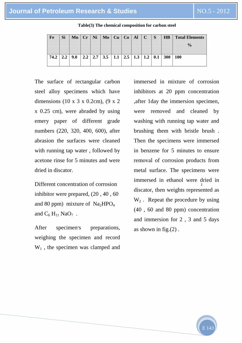
analyst as shown in Table (3):
Journal of Petroleum Research & Studies NO.5 - 2012
E 143
Table(3) The chemical composition for carbon steel