Evaluation of sandwich panels with various polyurethane foam-coresand ribs
Hesham Tuwair a, Matthew Hopkins a, Jeffery Volz b, Mohamed A. ElGawady a, *,Mohaned Mohamed c, K. Chandrashekhara c, Victor Birman d
a Department of Civil, Architectural, and Environmental Engineering, Missouri University of Science and Technology, USAb School of Civil Engineering and Environmental Science, The University of Oklahoma, USAc Department of Mechanical and Aerospace Engineering, Missouri University of Science and Technology, USAd Engineering Education Center, Missouri University of Science and Technology, USA
a r t i c l e i n f o
Article history:Received 12 December 2014Received in revised form15 March 2015Accepted 15 April 2015Available online 23 April 2015
Keywords:A. FoamsA. Glass fibresC. Finite element analysis (FEA)C. Analytical modeling
* Corresponding author.E-mail addresses: [email protected] (H. Tuwair), ms
The objective of this study was to evaluate three potential core alternatives for glass fiber reinforcedpolymer (GFRP) foam-core sandwich panels. The proposed system could reduce the initial productioncosts and the manufacturing difficulties while improving the system performance. Three differentpolyurethane foam configurations were considered for the inner core, and the most suitable system wasrecommended for further prototyping. These configurations consisted of high-density polyurethanefoam (Type 1), a bidirectional gridwork of thin, interconnecting, GFRP webs that is in-filled with low-density polyurethane foam (Type 2), and trapezoidal-shaped, low-density polyurethane foam utilizingGFRP web layers (Type 3). The facings of the three cores consisted of three plies of bidirectional E-glasswoven fabric within a compatible polyurethane resin. Several types of small-scale experimental in-vestigations were conducted. The results from this study indicated that the Types 1 and 2 cores werevery weak and flexible making their implementation in bridge deck panels less practical. The Type 3 corepossessed a higher strength and stiffness than the other two types. Therefore, this type is recommendedfor the proposed sandwich system to serve as a candidate for further development. Additionally, a finiteelement model (FEM) was developed using software package ABAQUS for the Type 3 system to furtherinvestigate its structural behavior. This model was successfully compared to experimental data indicatingits suitability for parametric analysis of panels and their design.
The majority of highway bridge decks are constructed withsteel-reinforced concrete. The life-span of such materials can besignificantly reduced by environmental conditions combined withwear from traffic, de-icing chemicals, and insufficient maintenance.As a result, transportation agencies have been endeavored to findnew cost-effective, reliable construction materials. Fiber reinforcedpolymer (FRP) has shown great promise in eliminating corrosionconcerns while also achieving a longer life-span with minimalmaintenance [1]. FRP has been used for columns [2e4], beams [5,6],
and panels [7e10]. FRP sandwich panels have many advantages,such as high flexural stiffness, strength, and environmental resis-tance, as well as reduced weight and life cycle cost. Using FRP deckpanels should also contribute to accelerated bridge construction.These advantages make FRP sandwich panels an excellent candi-date for construction of bridge decks.
Sandwich panels are often composed of two thin facings that arebonded to a much thicker core. The facings are typically made ofhigh strength and stiffness material. The core usually consists of arigid-foam, which has a low tomoderate strength and stiffness [11].However, the core design is industry-related. The facings are largelyresponsible for carrying flexural loads while the core providesshear capacity and integrity of the structure [12]. Many alternativeforms of sandwich panels can be accomplished by combingdifferent facings and core materials combined with varying ge-ometries. As a result, optimum designs can be produced for specificapplications [11].
H. Tuwair et al. / Composites Part B 79 (2015) 262e276 263
Researchers and manufacturers have developed many FRPbridge deck designs with honeycomb and cellular cores made of E-glass reinforced polyester or vinyl ester resin. These designs haveprimarily been manufactured using filament winding, hand lay-up,and pultrusion methods [13]. A honeycomb core is one of thefamous cores that being used in sandwich panels, implemented inbridge decks [8,14e20]. The honeycomb core consists of sinusoidalwave corrugations and straight components sandwiched betweenthe facings. Testing showed that this type of panels is effective inproviding high mechanical performance for minimum unit weight[14,19].
Researchers have proposed alternative forms for sandwichpanels. Potluri et al. [21] proposed a conventional sandwich panelwhere the top and bottom facings were separated by a foam core. Intheir study, they introduced FRP stitches to improve the foam coreperformance. The stitches were used also to prevent core-to-facingdebonding. It was found that both static and fatigue structuralbehavior can be improved by stitching together the top and bottomfacings. Hassan et al. and Reis and Rizkalla [22,23] proposed analternative system for FRP bridge decks. The proposed panel usedthree-dimensional fibers (stitches through foam cores) to connectthe top and bottom GFRP facings. They observed that the delami-nation concerns were overcome. In addition, the fiber reinforcedstitches increased significantly the core shear modulus. Dawoodet al. [24] studied the fatigue behavior of sandwich panels withflexible and stiff cores. They found that the panels with flexiblecores exhibit less degradation than those with stiffer cores due tothe higher induced shear stresses at the same level of applied shearstrain. Zureick [25] used finite element analysis to study differentcross-sections of simply supported FRP decks. This study comparedfour different cross-sections, concluding that the box shaped and Vshaped cores behaved much better than the other sections.Although the results from these studies provided a noteworthyunderstanding of FRP sandwich panel's behavior, most of theseresults cannot be extrapolated to other products.
The connection between the deck panels to the underlying steelgirders is typically made using adhesive glue at the interface, shearstuds, bolted connection, or steel clamps in a simply supportedcondition [26e29].
2. Paper scope and objectives
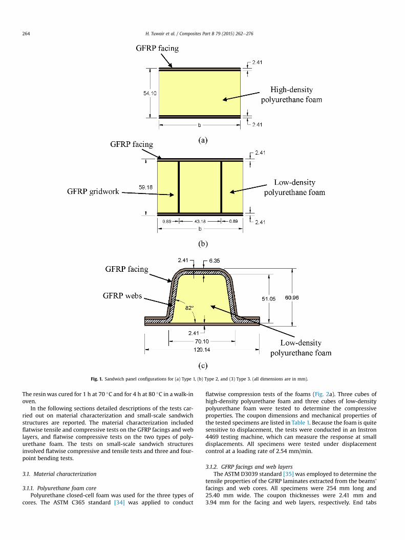
In the present study, small-scale FRP sandwich beams havingthree different foam core configurations (see Fig. 1) were investi-gated. The proposed system could reduce the initial productioncosts and the manufacturing difficulties while improving the sys-tem performance. The facings of the proposed three sandwichbeams consist of E-glass woven fabric within a compatible poly-urethane resin. Each configuration uses polyurethane foam as aninfill material for the inner core. The investigated core configura-tions include high-density polyurethane foam (Type 1), a gridworkof thin, interconnecting, GFRPwebs that is infilled with low-densitypolyurethane foam (Type 2), and GFRP trapezoidal-shaped infilledwith low density polyurethane foam (Type 3). The polyurethanefoam was chosen because it provides several advantages. Theseadvantages include:
▪ Lower material and labor costs.▪ Higher impact resistance and damping.▪ Compatiblematerial to the polyurethane resin, which aids in theinfusion process and bonding with the face sheets.
A polyurethane resin system was used in the proposed sand-wich beams as it has good high resistance and superior mechanicalproperties compared to polyester and vinyl ester [30]. This resin
systemwas also chosen because it can reduce the initial costs of thesandwich beams. The one-step Vacuum Assisted Resin TransferMolding (VARTM) process was also chosen to manufacture beamsas it has a lower production cost than other manufacturingmethods. For instance, the production cost of pultruded deckpanels is approximately five times the production cost of hand lay-up deck panels [31]. The VARTM process can be used to manufac-ture both small and large FRP bridge deck panels. Although, poly-urethane resin has a low pot life, recent modifications to the resinenabled it to be used with the VARTM process. A thermoset poly-urethane resin with a longer pot life developed by Bayer Materi-alScience was used in this study to manufacture the sandwichbeams. All specimens were manufactured in the CompositesManufacturing Laboratory, Department of Mechanical and Aero-space Engineering, Missouri University of Science and Technology.
One of the greatest challenges faced by structural sandwichbeams/panels is that the inner core has low transverse stiffness andstrength. As a result, these panels are vulnerable to in-plane shear,wrinkling instability, and face-to-core deboning [32]. Therefore, thethree design criteria considered in this study were chosen toimprove the core's mechanical performance. The high-densityfoam in the first type was used with no webs in the core in anattempt to minimize both weight and cost. The cores in the secondand third types consisted of low-density foam to minimize theweight reinforced with GFRP webs. Furthermore, the web elementsof Types 2 and 3 potentially will delay both delamination failureand local crushing.
This paper compares the structural characteristics of the threeproposed sandwich beam systems. The compressive and tensilestrengths were assessed through the flatwise compressive andtensile tests of small sandwich cubes and coupon tests. The flexuralstrength and bending stiffness of each core system were alsoevaluated through three and four-point bending tests. The possiblemodes of failure of the different core configurations were alsodetermined. A finite element model (FEM) was also developed forthe Type 3 system and verified using the experimental results. TheFEM was used for a better understanding of the structural behaviorof this sandwich beam type.
A full-scale of Type 3 system was recently manufactured by theStructural Composites, Inc [33]. Based on the manufacturer, theresulting costs of the panel system was less than one half the costof a comparable honeycomb FRP deck construction. Additionally,on a production run for an actual bridge, the manufacture esti-mates a further decrease in unit costs of 40%e50%, bringing theFRP deck alternative in line with initial costs of reinforced concretedecks.
3. Experimental program
This study examined the cross-sections of three different con-figurations of the closed-cell polyurethane infill-foam beams (seeFig. 1). The facings of the three types consisted of three plies ofbidirectional E-Glass woven fabric (WR18/3010) infused with acompatible polyurethane resin. The core of Type 1 was comprisedof high-density polyurethane foam that had a mass density of96 kg/m3. The Type 2 core consists of thin, interconnecting, glassfiber/resin webs that form a bidirectional FRP gridwork that isinfilled with a low-density polyurethane foam of 32 kg/m3. TheType 3 core was comprised of a trapezoidal-shaped, low-density,polyurethane foam and three-ply web layers (E-BXM1715).
The dry fabric and foam were stacked together in a rigidaluminum mold. High permeability layers placed over the fibersreduced infusion time, and a standard peel ply prevented the resinfrom adhering to the vacuum bag. Then, the thermoset poly-urethane resin was infused through the vacuum-assisted process.
Fig. 1. Sandwich panel configurations for (a) Type 1, (b) Type 2, and (3) Type 3. (all dimensions are in mm).
H. Tuwair et al. / Composites Part B 79 (2015) 262e276264
The resinwas cured for 1 h at 70 �C and for 4 h at 80 �C in a walk-inoven.
In the following sections detailed descriptions of the tests car-ried out on material characterization and small-scale sandwichstructures are reported. The material characterization includedflatwise tensile and compressive tests on the GFRP facings and weblayers, and flatwise compressive tests on the two types of poly-urethane foam. The tests on small-scale sandwich structuresinvolved flatwise compressive and tensile tests and three and four-point bending tests.
3.1. Material characterization
3.1.1. Polyurethane foam corePolyurethane closed-cell foam was used for the three types of
cores. The ASTM C365 standard [34] was applied to conduct
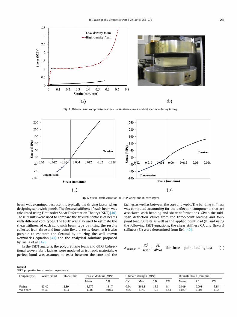
flatwise compression tests of the foams (Fig. 2a). Three cubes ofhigh-density polyurethane foam and three cubes of low-densitypolyurethane foam were tested to determine the compressiveproperties. The coupon dimensions and mechanical properties ofthe tested specimens are listed in Table 1. Because the foam is quitesensitive to displacement, the tests were conducted in an Instron4469 testing machine, which can measure the response at smalldisplacements. All specimens were tested under displacementcontrol at a loading rate of 2.54 mm/min.
3.1.2. GFRP facings and web layersThe ASTM D3039 standard [35] was employed to determine the
tensile properties of the GFRP laminates extracted from the beams'facings and web cores. All specimens were 254 mm long and25.40 mm wide. The coupon thicknesses were 2.41 mm and3.94 mm for the facing and web layers, respectively. End tabs
Fig. 2. Test setup for (a) flatwise foam compressive test, (b) tensile coupon test, and (c) compressive coupon test.
Table 1Polyurethane foam properties from compressive tests.
*S.D: Standard deviation.*C.V: Coefficient of variation (%).
H. Tuwair et al. / Composites Part B 79 (2015) 262e276 265
holding the specimen were 63.50 mm long. The tension test wasconducted in an MTS-880 testing machine (see Fig. 2b) with aloading rate of 1.27 mm/min. The longitudinal strains were recor-ded using electrical strain gauges of 350 U at the middle of thecoupons. Three coupons from the facings and three from the webcore were also tested in compression (see Fig. 2c), according to theASTM D3410 standard [36]. The coupon dimensions used incompressive tests were 147.32 mm long and 25.40 mm wide; thegauge length was 20.32 mm. The displacement rate of the test wasset to 0.127 mm/min. Two strain gauges were attached to the gaugelength between the end taps was 147.32 mm long and 25.40 mm.
3.2.1. Flatwise compressive testsSix specimenswere tested: three for Type 1 and three for Type 2.
Flatwise compressive strength and elastic modulus for the sand-wich core's structural design properties were determined usingMTS-880 universal testing machine and following ASTM C365standard [35] (see Fig. 3a). Since the main purpose of the low-density polyurethane foam of the Type 3 core is its use as a moldfor the trapezoidal-shaped FRP layers, the bare foam was testedwithout any FRP, as demonstrated in the material characterizationsection. Specimens of Types 1 and 2 had a constant square cross-section of 88.90 mm � 88.90 mm corresponding to a cross-sectional area of 7903 mm2 which was smaller than the10,323 mm2 area recommended by the ASTM C365 [34]. Thecomposite thickness of Type 1 and 2 was 54.10 mm and 59.18 mm,respectively. Each specimen was centered under the loading plateto ensure a uniform load distribution. The speed of the crossheaddisplacement was set at a rate of 2.54 mm/mm.
3.2.2. Flatwise tensile testsMTS-880 universal testing machine was used to conduct the
flatwise tensile tests (Fig. 3b) according to the ASTM C297 standard[37]. Six specimens were tested (three for Type 1 and three for Type2) to determine the flatwise tensile strength of core. This test alsoprovided information on the quality of the core-to-facing bond.
Similar to the flatwise compression tests, Types 1 and 2 had aconstant square cross-section of 88.90 mm � 88.90 mm corre-sponding to a cross-sectional area of 7903 mm2, which was largerthan 645.16 mm2 recommended by the ASTM C297 [37]. Thecomposite thickness of Type 1 and 2 was 54.10 mm and 59.18 mm,respectively. In order to be gripped in the test frame, each specimenwas adhesively bonded to T-shape steel sections with an epoxyadhesive supplied by the 3M Company. The loading rate was set at1.27 mm/min.
3.2.3. Flexural testsThree-point bending tests were conducted on short beams and
four point bending tests on long beams in accordance with ASTMC393 standard [38]. The test setup is illustrated in Fig. 4. AWyoming test fixture (model no. CU-LF) was used [39]. Thick steelplates and high resistance rubber pads (with a shore A hardness of60) were inserted at the loading and supporting points to distributethe load uniformly and reduce the stress concentrations. The loadwas applied using an Instron 4469 testing machine with a loadcapacity of 50 kN and a displacement rate of 1.27e2.54mm/min. Allspecimens were tested under displacement control.
The objective of the three-point bending test is to generate theshear stresses by using relatively short beams and analyze theirimpact on the total deflection. A total of nine short beams wereinvestigated: four for Type 1, four for Type 2, and one for Type 3.Each specimen was tested over a clear span of 152.40 mmwith theload applied at the center of the beam (see Fig. 4a). Four-pointbending tests were conducted (Fig. 4b) to investigate the effect ofthe three types of cores on flexural behavior of the sandwich beamsby increasing the span length. Three specimens of each type wereinvestigated, i.e. a total of nine sandwich beams were examined.They were tested in one-way bending with the span of 609.60 mm,under two equal point loads, applied at 203.20 mm from eachsupport. The specimens were loaded to failure at a displacementrate of 1.27e2.54 mm/min.
Strains in the axial direction of the beams were measured withelectrical, high precision strain gauges (produced by Micro Mea-surements Group) at a resistance of 350U. The bottom deflection at
Fig. 3. Test setup for flatwise sandwich: (a) compressive test, and (b) tensile test for Type 1.
Fig. 4. Test setup for (a) three-point, and (b) four-point bending tests for Type 1.
H. Tuwair et al. / Composites Part B 79 (2015) 262e276266
mid-span was recorded using a Linear Potentiometer (LP). A LinearVariable Differential Transducer (LVDT) was mounted on themovable frame of the machine to monitor top deflection at mid-span. The long beams, used for the four-point bending, hadgauges attached to the top and bottom of the facesheet surface atthe middle of the beam. The short beams, used for the three-pointbending, had one gauge attached at the bottom of the facesheet
surface (at the middle of the beam). A data acquisition system wasused to record the load, displacement, and strain during testing.
4. Assessment of flexural stiffness (EI)
The flexural stiffness (EI) where E is the equivalent modulus ofelasticity and I is the equivalent moment of inertia of the sandwich
Fig. 5. Flatwise foam compressive test: (a) stressestrain curves, and (b) specimen during testing.
Fig. 6. Stressestrain curve for (a) GFRP facing, and (b) web layers.
H. Tuwair et al. / Composites Part B 79 (2015) 262e276 267
beam was examined because it is typically the driving factor whendesigning sandwich panels. The flexural stiffness of each beamwascalculated using First-order Shear Deformation Theory (FSDT) [40].These results were used to compare the flexural stiffness of beamswith different core types. The FSDT was also used to estimate theshear stiffness of each sandwich beam type by fitting the resultscollected from three and four-point flexural tests. Note that it is alsopossible to estimate the flexural by utilizing the well-knownNewmark's equation [41] and the analytical solutions proposedby Faella et al. [42].
In the FSDT analysis, the polyurethane foam and GFRP bidirec-tional woven fabric facings were modeled as isotropic materials. Aperfect bond was assumed to exist between the core and the
Table 2GFRP properties from tensile coupon tests.
Coupon type Width (mm) Thick. (mm) Tensile Modulus (MPa)
facings as well as between the core and webs. The bending stiffnesswas computed accounting for the deflection components that areassociated with bending and shear deformations. Given the mid-span deflection values from the three-point loading and four-point loading tests as well as the applied point load (P) and usingthe following FSDT equations, the shear stiffness GA and flexuralstiffness (EI) were determined from Ref. [40]:
Fig. 7. Flatwise sandwich compressive tests: (a) stressestrain curves, (b) failure mode of Types 1, and (c) failure mode of Types 2.
H. Tuwair et al. / Composites Part B 79 (2015) 262e276268
Dmidspan ¼ 23PL3
1296EIþ PL6kGA
for four� point loading test (2)
where L is the span length and k is the shear correction factor(which was assumed to be 5/6).
5. Experimental results
5.1. Material characterizations
5.1.1. Polyurethane foam coreFig. 5a illustrates the average compressive stressestrain curves
of the tested low (soft) and high-density (rigid) polyurethane foamcubes. These curves are linear in the elastic region, with a yield
Table 4Summary of flatwise sandwich compressive tests.
Panel type Results Width ¼ length (mm) Thick. (mm) Yield
Type 1 Average 88.90 54.10 1.04S.D 0.011C.V 1.01
Type 2 Average 88.90 59.18 1.18S.D 0.030C.V 2.55
region at an average stress of 0.056 MPa for the low-density foamand 1.04 MPa for the high-density foam. The yield behavior can beexplained by the buckling of the foam's internal walls. A long flatplateau was followed. Then, a densification (hardening) region wascreated by a gradual stress increase when the cell walls werestacked prior to final densification. No visible signs of failure wereobserved (see Fig. 5b). Residual displacement of the collapsed foamdid, however, occur once the unloading stage was complete.
5.1.2. GFRP facings and web layersFig. 6a illustrates average axial tensile and compressive
stressestrain curves for the GFRP facing. In the tensile test, thefacing exhibited a linear elastic response up to strain of 0.019 mm/mm at an ultimate stress of 264.7 MPa. In the compressive test, theultimate compressive strength was 102.73 MPa, or 38.8% of its
Type 1 Average 88.90 54.10 0.79 0.016 47.23S.D 0.024 0.001 0.49C.V 3.09 5.91 1.03
Type 2 Average 88.90 59.18 1.12 0.012 96.80S.D 0.35 0.001 19.87C.V 31.14 10.20 20.53
Table 6Test results of three-point bending tests.
Panel type Results Width [b] (mm) Depth (mm) Span (mm) Pu (kN) Du (mm) εmax (mm/mm) Failure mode
Type 1 Average 76.45 54.10 152.40 5.16 8.64 0.0060 Indentation þ crushingS.D 0.34 0.66 0.0008C.V 6.62 7.68 14.48
Type 2 Average 76.45 59.18 6.27 1.12 0.0023 BucklingS.D 1.28 0.25 0.001C.V 20.47 23.39 43.56
Type 3 e See Fig. 1 60.96 21.12 6.10 0.0054 Wrinkling
H. Tuwair et al. / Composites Part B 79 (2015) 262e276 269
ultimate tensile strength. Fig. 6b presents average axial tensile andcompressive stressestrain curves of the web layers of the Type 3beam. The curve exhibited nonlinear behavior due to re-orientationof þ45/-45 fibers. The ultimate tensile strain was 0.027 mm/mmcorresponding to the ultimate stress of 137.9 MPa. In thecompression region, the ultimate compressive strength was102.73 MPa, or 73.5% of its ultimate tensile strength. These prop-erties were also valid in the transverse direction for both the facingsand the web layers due to the symmetric quasi-isotropic architec-ture of the reinforcing fibers. The observed failure mode for thefacing and web layer coupons under tension was a sudden kinkrupture and shear rupture, respectively. All tested coupons faileddue to micro buckling and kinking of the fibers under compression.A summary of the results collected from the coupon tests is con-tained in Tables 2 and 3.
5.2.1. Flatwise compressive testsFlatwise compressive tests were conducted on sandwich cubes
for the first two types to examine the properties of their cores.Fig. 7a displays the compressive stressestrain responses for Types 1and 2. For Type 1, the curve follows a typical behavior of cellularmaterials [43]. The first part of the curve was linear in the elasticregion, followed by the plateau region where the stress was almostconstant under increasing deformation. Then, there was a sharplyincreasing loading region at a large strain corresponding to solidi-fication. The yield region occurred at an average stress of 1.04 MPa.This yield behavior was attributed to buckling of the foam's internalcell walls. The flat plateau was produced by the development oflocalized buckling within the cell walls. As the deformation
Fig. 9. Three-point bending tests: (a) load vs. mid-span deflection, and (b) load vs.mid-span bottom strains.
H. Tuwair et al. / Composites Part B 79 (2015) 262e276270
increased, the cell walls stacked on top of each other resulting inthe closure of most of the voids. Therefore, the foam becamedensified and displayed higher strength. A deformed shape of theType 1 foam is shown in Fig. 7b. For Type 2, the stressestrain curveillustrates that the web core foam initially exhibited a nearly linearbehavior up to the maximum stress, which had an average value of1.18 MPa. It was noticed that the failure mode of this type wasbuckling of the thin FRP webs and subsequent delamination be-tween the foam and the webs, as shown in Fig. 7c. A summary ofthe test results for Types 1 and 2 is presented in Table 4.
5.2.2. Flatwise tensile testsThe flatwise tensile properties of the first two types of the
sandwich cubes were determined. Fig. 8a presents the stresse-strain curves for Types 1 and 2. For Type 1, the response waslinearly-elastic up to failure. The failure mode for all of the testedType 1 specimens was cohesive rupture of the core, which dis-played a cup-cone surface (Fig. 8b). The average ultimate tensilestrength and the ultimate tensile strain were approximately0.79 MPa and 0.016 mm/mm, respectively. These results aresummarized in Table 5. For Type 2, the curve was linearly elasticup to a strain of 0.0076 mm/mm. Beyond this strain, the responsebecame slightly nonlinear until the specimen ruptured. This
nonlinearity was produced by the foam's contribution to tensileresistance. The average ultimate stress and strain were 1.12 MPaand 0.012 mm/mm, respectively. Because of low strength andstiffness of the low-density foam, the initial failure of the foamwas Mode I fracture characterized by horizontal cracks. Then, adebonding between the FRP gridwork and the facing occurred, asobserved in Fig. 8c.
5.2.3. Flexural behaviorTable 6 summarizes the results gathered from the three-point
bending tests. Fig. 9a presents the load deflection curves at themid-span for the three core types. For Type 1, all sandwich beamsexhibited a linear behavior up to a deflection of approximately2.79 mm. At larger deflections nonlinearity occurred with stiffnesssoftening up to failure. This behavior can be attributed to thecrushable nature of the polyurethane foam. The average of themaximum vertical deflection and the longitudinal bottom strainthat were recorded at mid-spanwere 8.64 mm and 0.006 mm/mm,respectively, at a failure load of 5.16 kN. The recorded strains (seeFig. 9b) at the bottom mid-span exhibited behavior similar to thatof the deflection response. As can be observed from the straincurve, the maximum strain value was significantly lower than theultimate strain of the GFRP facing, which is attributed to theobserved failure mode. All specimens failed due to an inward localbending of the compression facing beneath the loading point, asshown in Fig. 10a, followed by crushing in the top facing and thefoam (Fig. 10b). The local bending occurred because the foam'scompressive strength and stiffness are insufficient to resist highlocal stresses.
Type 2 specimens were loaded up to failure. It should be notedfrom Table 6 that the standard deviation of this type is relativelyhigh. This can be attributed to the distribution of transversewebs aseach specimen had a different arrangement due to cutting it from adifferent location from the large panel. The curve in Fig. 9 suggests anearly linear response up to failure. The average of the maximumdeflection and longitudinal strain recorded at mid-span were1.12 mm and 0.0023 mm/mm, respectively, at an average failureload of 6.27 kN. The initial failure mode was buckling of the FRPwebs coupled with compressive failure in the foam, as depicted inFig. 10c. Due to post buckling deformations of the webs, the webssubsequently fractured, and the top facing wrinkled inward.
For Type 3 specimens, due to a limited amount of trapezoidalpolyurethane foam available, only one specimen was tested. Fig. 9aillustrates the tested beam's load-deflection response. In a mannersimilar to the other two types, the Type 3 specimen also exhibited alinear behavior up to failure as reflected in the strain gauge readingin Fig. 9b. The average of the maximum deflection recorded at mid-span was approximately 6.10 mm at failure load of 21.12 kN. Thesandwich beam initially failed by delamination between the weblayers and the foam at one corner. The ultimate failure modeincluded wrinkling of the top facing. This wrinkling was followedby crushing of the web layers under the loading point (see Fig. 10d).It should be noted that the stiffness of the Type 3 curve was slightlylower than of the Type 2, a result that was not anticipated. Overall,these tests revealed that local failures, rather than global shearfailures dominated flexural response. The results provided loadversus displacement responses which were needed to estimate theflexural stiffness of each sandwich type.
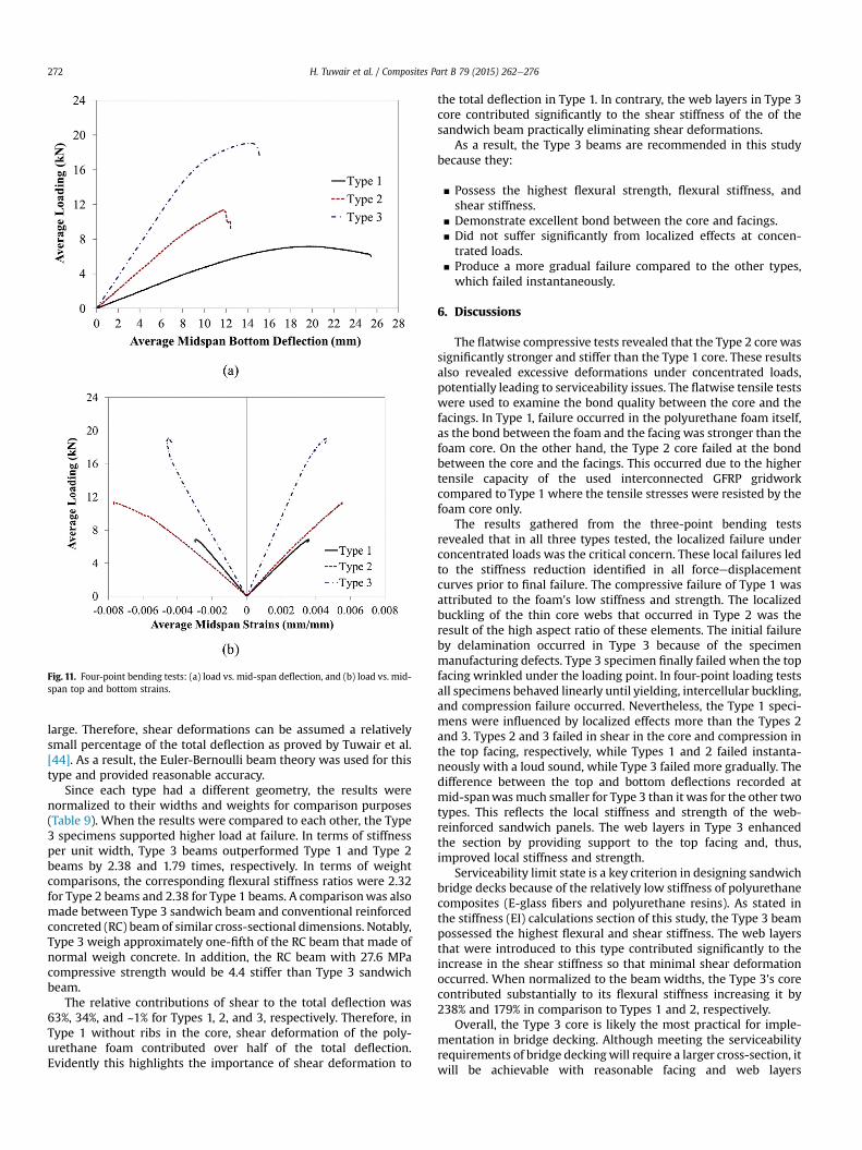
Table 7 summarizes the results collected from the four-pointbending tests. These results were presented in terms of the ulti-mate load, deflection, and strain in both the upper and lower fac-ings at the ultimate load, and the observed failure modes. Fig. 11apresents a load-deflection curve for each of the three types tested.The behavior of each type clearly demonstrated the significant ef-fect produced by the type of core used. In general, all beam types
Fig. 10. Failure modes: (a) local buckling, (b) crushing of the top facing and foam in Type 1, (c) buckling of the webs and compressive failure in the foam in Type 2, and (d) wrinklingof the top facing and crushing of the webs in Type 3.
Table 7Test results of four-point loading tests.
Panel type Results Pu (kN) Width [b] (mm) Depth (mm) Span (mm) Du (mm) Bottom-face εmax
(mm/mm)Top-face εmax
(mm/mm)Failure mode
Type 1 Average 7.0 102.11 54.10 609.60 21.08 0.0037 �0.0038 Bending fracture or shear failureS.D 0.14 1.21 0.0003 0.0006C.V 1.94 5.71 6.63 15.87
Type 3 e 19.1 See Fig. 1 60.96 14.22 0.0046 �0.0045 Compression failure
H. Tuwair et al. / Composites Part B 79 (2015) 262e276 271
behaved linearly until a certain load. The linear behavior was fol-lowed with a nonlinear response that was produced by sheardeformation of the polyurethane core. Nonlinearity in the straincurves (see Fig. 11b) was not observed because strain measure-ments were taken at the facing surface, reflecting the facing's linearbehavior. Themaximum strains measured on both the compressionand tension facings were significantly lower than the ultimatestrain measured in the compression and the tension couponspecimens (0.019), which is also attributed to each beam becausethe strength of the facing materials is high, so that it would beimpossible to cause compressive or tensile failure at this spanlength.
The average mid-span recorded deflection for the Type 1 spec-imens was 21.10 mm at an approximate ultimate load of 7.0 kN. Theinitial failure mode occurred when the core yielded under theloading points and the top face sheet wrinkled. All Type 1 sandwichbeams exhibited either a bending fracture in the top facing or ashear failure in the core followed by debonding (see Fig. 12a and b,respectively). The top facing in Type 2 initially failed due to inter-cellular buckling (Fig. 12c). Shear failure in the core material(Fig. 12d) was the ultimate failure mode. As shown in Table 7, the
ultimate loads had a high degree of variability. This variability wasattributed to the number of longitudinal webs within each spec-imen; one specimen had three longitudinal webs, and the othertwo had two. The maximum measured deflection at mid-span forthe Type 3 specimens was 14.22 mm at an ultimate load ofapproximately 19.10 kN (Fig. 11a). The behavior was linear with asubsequent softening nonlinear response prior to reaching the ul-timate load capacity. This softening nonlinearity could be attrib-uted to compression failure under the loading points andassociated nonlinear response of the foam (Fig. 12e). The ultimatefailure was caused by excessive compressive stresses in the webs,which created a hinge mechanism in the top facing under theloading point (Fig. 12f).
5.3. Stiffness (EI) calculations
Flexural stiffness of Types 1 and 2 was estimated using FSDTequations (1) and (2), and the results are listed in Table 8. Theflexural stiffness for Type 3 was based on the deflection associatedwith bending from the four-point loading test only. The shearstiffness, based on the geometry of Type 3, was expected to be very
Fig. 11. Four-point bending tests: (a) load vs. mid-span deflection, and (b) load vs. mid-span top and bottom strains.
H. Tuwair et al. / Composites Part B 79 (2015) 262e276272
large. Therefore, shear deformations can be assumed a relativelysmall percentage of the total deflection as proved by Tuwair et al.[44]. As a result, the Euler-Bernoulli beam theory was used for thistype and provided reasonable accuracy.
Since each type had a different geometry, the results werenormalized to their widths and weights for comparison purposes(Table 9). When the results were compared to each other, the Type3 specimens supported higher load at failure. In terms of stiffnessper unit width, Type 3 beams outperformed Type 1 and Type 2beams by 2.38 and 1.79 times, respectively. In terms of weightcomparisons, the corresponding flexural stiffness ratios were 2.32for Type 2 beams and 2.38 for Type 1 beams. A comparisonwas alsomade between Type 3 sandwich beam and conventional reinforcedconcreted (RC) beam of similar cross-sectional dimensions. Notably,Type 3 weigh approximately one-fifth of the RC beam that made ofnormal weigh concrete. In addition, the RC beam with 27.6 MPacompressive strength would be 4.4 stiffer than Type 3 sandwichbeam.
The relative contributions of shear to the total deflection was63%, 34%, and ~1% for Types 1, 2, and 3, respectively. Therefore, inType 1 without ribs in the core, shear deformation of the poly-urethane foam contributed over half of the total deflection.Evidently this highlights the importance of shear deformation to
the total deflection in Type 1. In contrary, the web layers in Type 3core contributed significantly to the shear stiffness of the of thesandwich beam practically eliminating shear deformations.
As a result, the Type 3 beams are recommended in this studybecause they:
▪ Possess the highest flexural strength, flexural stiffness, andshear stiffness.
▪ Demonstrate excellent bond between the core and facings.▪ Did not suffer significantly from localized effects at concen-trated loads.
▪ Produce a more gradual failure compared to the other types,which failed instantaneously.
6. Discussions
The flatwise compressive tests revealed that the Type 2 core wassignificantly stronger and stiffer than the Type 1 core. These resultsalso revealed excessive deformations under concentrated loads,potentially leading to serviceability issues. The flatwise tensile testswere used to examine the bond quality between the core and thefacings. In Type 1, failure occurred in the polyurethane foam itself,as the bond between the foam and the facing was stronger than thefoam core. On the other hand, the Type 2 core failed at the bondbetween the core and the facings. This occurred due to the highertensile capacity of the used interconnected GFRP gridworkcompared to Type 1 where the tensile stresses were resisted by thefoam core only.
The results gathered from the three-point bending testsrevealed that in all three types tested, the localized failure underconcentrated loads was the critical concern. These local failures ledto the stiffness reduction identified in all forceedisplacementcurves prior to final failure. The compressive failure of Type 1 wasattributed to the foam's low stiffness and strength. The localizedbuckling of the thin core webs that occurred in Type 2 was theresult of the high aspect ratio of these elements. The initial failureby delamination occurred in Type 3 because of the specimenmanufacturing defects. Type 3 specimen finally failed when the topfacing wrinkled under the loading point. In four-point loading testsall specimens behaved linearly until yielding, intercellular buckling,and compression failure occurred. Nevertheless, the Type 1 speci-mens were influenced by localized effects more than the Types 2and 3. Types 2 and 3 failed in shear in the core and compression inthe top facing, respectively, while Types 1 and 2 failed instanta-neously with a loud sound, while Type 3 failed more gradually. Thedifference between the top and bottom deflections recorded atmid-spanwasmuch smaller for Type 3 than it was for the other twotypes. This reflects the local stiffness and strength of the web-reinforced sandwich panels. The web layers in Type 3 enhancedthe section by providing support to the top facing and, thus,improved local stiffness and strength.
Serviceability limit state is a key criterion in designing sandwichbridge decks because of the relatively low stiffness of polyurethanecomposites (E-glass fibers and polyurethane resins). As stated inthe stiffness (EI) calculations section of this study, the Type 3 beampossessed the highest flexural and shear stiffness. The web layersthat were introduced to this type contributed significantly to theincrease in the shear stiffness so that minimal shear deformationoccurred. When normalized to the beam widths, the Type 3's corecontributed substantially to its flexural stiffness increasing it by238% and 179% in comparison to Types 1 and 2, respectively.
Overall, the Type 3 core is likely the most practical for imple-mentation in bridge decking. Although meeting the serviceabilityrequirements of bridge deckingwill require a larger cross-section, itwill be achievable with reasonable facing and web layers
Fig. 12. Failure modes: (a) bending fracture, (b) shear failure in Type 1, (c) intercellular buckling, (d) shear failure in Type 2, (e) deformed shape during testing, and (f) compressionfailure under loading points in Type 3.
Table 8Calculated stiffness results.
Panel type Flexural stiffness (EI) (kN$mm2) Shear stiffness (GA) (kN)
Mean S.D C.V Mean S.D C.V
1 5,056,821 650,934 12.9 91.7 1.3 1.42 6,549,876 1,014,418 15.5 391.2 25.1 6.43 8,865,849 e e ~∞ e e
Table 9Normalized stiffness values.
Panel type Width (mm) Mass density (kN/m3)
1 102.11 203.22 105.66 208.43 83.06 484.4
H. Tuwair et al. / Composites Part B 79 (2015) 262e276 273
thicknesses, as well as a smaller and more practical panel depththan in the other two construction types. The typical size of a full-scale deck panel is five feet wide by eight feet long. The span(2.44 m) of the panel will be perpendicular to the traffic directionand will be simply supported on the short dimensions (1.52 m).Thus, the system would behave as a flexural system in theperpendicular direction to traffic and as a truss system in the par-allel direction. The design of the panel will be based on the standardAASHTO Truck or Tandem [45], whichever controls a particularaspect. In accordancewith FHWA guidelines, panel stressesmust belimited to 20% of the ultimate strength. Deflection should be limited
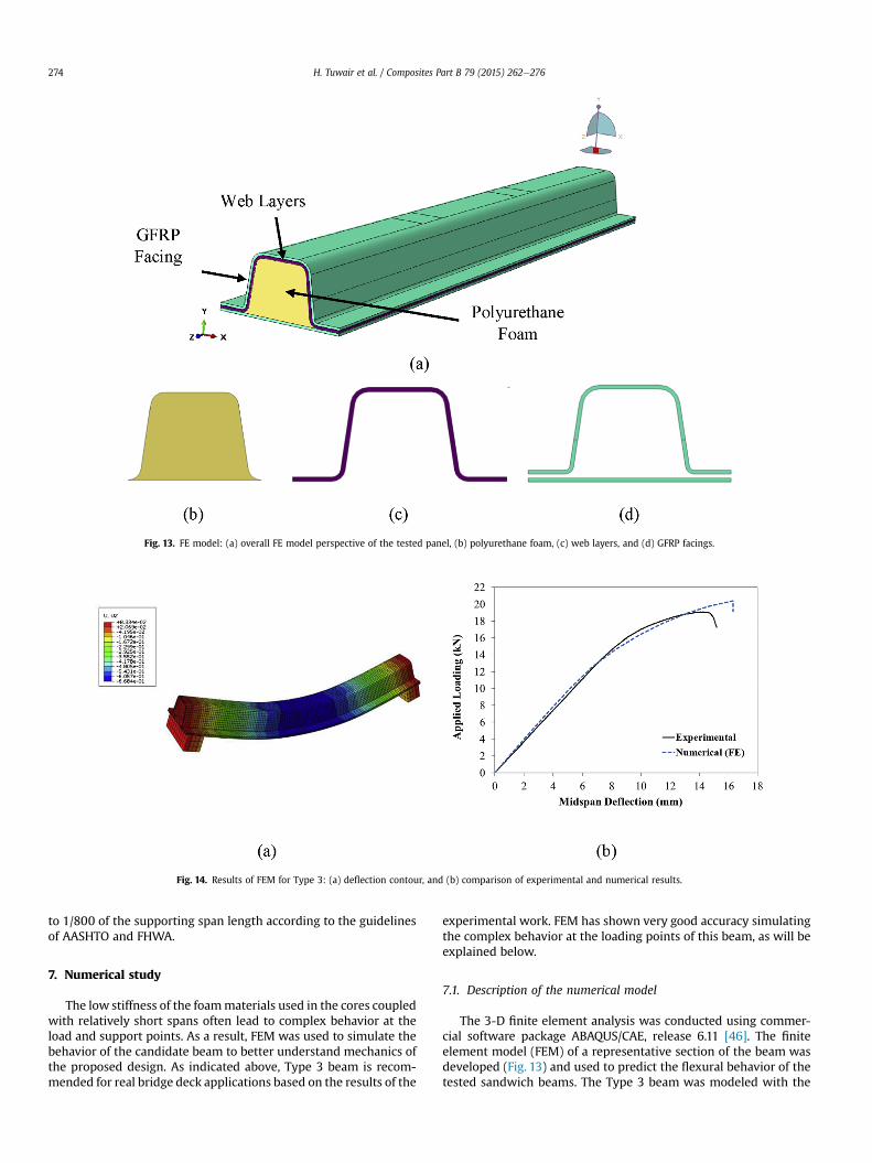
Fig. 13. FE model: (a) overall FE model perspective of the tested panel, (b) polyurethane foam, (c) web layers, and (d) GFRP facings.
Fig. 14. Results of FEM for Type 3: (a) deflection contour, and (b) comparison of experimental and numerical results.
H. Tuwair et al. / Composites Part B 79 (2015) 262e276274
to 1/800 of the supporting span length according to the guidelinesof AASHTO and FHWA.
7. Numerical study
The low stiffness of the foammaterials used in the cores coupledwith relatively short spans often lead to complex behavior at theload and support points. As a result, FEM was used to simulate thebehavior of the candidate beam to better understand mechanics ofthe proposed design. As indicated above, Type 3 beam is recom-mended for real bridge deck applications based on the results of the
experimental work. FEM has shown very good accuracy simulatingthe complex behavior at the loading points of this beam, as will beexplained below.
7.1. Description of the numerical model
The 3-D finite element analysis was conducted using commer-cial software package ABAQUS/CAE, release 6.11 [46]. The finiteelement model (FEM) of a representative section of the beam wasdeveloped (Fig. 13) and used to predict the flexural behavior of thetested sandwich beams. The Type 3 beam was modeled with the
Fig. 15. Failure modes and contours of longitudinal principal stresses. The compressive stresses concentrations at the loading points are observed both in experiments and in FEM.
H. Tuwair et al. / Composites Part B 79 (2015) 262e276 275
same geometry (Fig. 1c) as that of the investigated beams. Thepolyurethane foam, webs, and facings (Fig. 13) were modeled with3-D continuum solid elements that had eight-node, integration-reduced, linear brick elements (C3D8R, hourglass control). Theseelements had three translational degrees of freedom (DOFs) at eachnode. The FRP composites of the facing and web layers have thesame volume fraction of the fibers in warp (longitudinal) and fill(transverse) directions. Moreover, the thickness of these layersbeing small compared to other beam dimensions, consequently thefacing and web layers were modeled as isotropic materials tosimplify the analysis. The properties were determined from thematerial characterization tests (Tables 1e3). The polyurethanefoam material was modeled using crushable foam model that isavailable in the ABAQUS library. The crushable foam model has thecapability to enhance the ability of a foam material to deform incompression because of the cell wall buckling process [46]. Theexperimental tests of Type 3 revealed that neither delamination norrelative slip occurred between the facing and the core duringtesting. Therefore, it is acceptable to assume a full contact (perfectbond) at the interface between the sandwich beam components.The specimen considered in the analysis was loaded and supportedby 38.10 mm-wide steel plates, which were free to rotate. The loadwas applied in displacement control at the metal plates to avoidstress concentration. Contact element was implemented betweenthe loading pads and the GFRP panel. A sensitivity analysis wasconducted on the effect of the type of the contact element betweenthe loading pads and the GFRP panel. Two different types of contactelements were investigated: tied contact elements and surfacecontact element. The first type of contact elements does not allowsliding between the beam surface and loading plate; however, thesecond contact elements enables such sliding controlled by a co-efficient of friction of 0.3. The results of the two models werealmost identical; however, the running time of the solution wasmuch lower in the case of tied contact elements. Therefore, tiedcontact elements were selected for the analysis. The displacement
was increased monotonically until the beam failed. The modelfailed when the FRP materials reached their ultimate tensile orultimate compressive stress.
7.2. Numerical results
Fig. 14a shows the deflection contours generated using FEM forType 3 specimen. Fig. 14b illustrates a comparison between theexperimentally measured deflection values and the deflectionpredicted by the FEM at mid-span of the tested beam. Goodagreement was observed between the experimental results and theFEM predictions. Overall, the FE model accurately captured thetested sandwich beam's behavior. The sandwich beam reached thepeak load of 19.10 kN at the ultimate deflection of 14.22 mm duringthe experiment. It reached the ultimate load of 20.37 kN at themaximum deflection of 16.25 mm according to the FEM analysis.The average maximum tensile strain at the mid-span's bottomfacing recorded during the experiment was equal to 0.0046 mm/mm. For the FEM, this value was 0.0058 mm/mm, a difference of20%. The FEM tended to slightly overestimate the predicteddeflection at mid-span. These differences occurred because of themanufacturing process that produced some variability in thethickness of both GFRP facings and the web layers. Failure in theFEM analysis occurred when the top facing at the applied pointloads reached the ultimate stress. This mode of failure matches theexperimental behavior (see Fig. 15).
8. Conclusions
The structural behavior of three different core alternatives forGFRP foam-infill sandwich panels was investigated. The results ofour experimental and numerical research demonstrated the engi-neering and economic feasibility of the proposed design.
All sandwich beams tested in bending exhibited a linear-elasticbehavior. This initial response was followed with a stiffness
H. Tuwair et al. / Composites Part B 79 (2015) 262e276276
softening prior to failure. The Type 3 construction exhibited betterstrength as well as flexural and shear stiffness than the other twotypes investigated in this research. This is due to the remarkableeffect of web layers. Also, excellent bondwas observed between thepolyurethane foam core and the facings in the Type 3 beams.
The Type 3 beamswere less vulnerable to localized stress effectsunder a concentrated load compared to the other two types. On theother hand, Types 1 and 2were quite susceptible to localized effectsunder concentrated loads, such as inward local bending andwrinkling of the compression facing under the concentrated loads,which resulted in a lower ultimate strength. Additionally, Types 1and 2 experienced large deflections associated with significantshear deformation of the core. The Type 3 beam prevented orreduced the facing-core debonding trend that has been observed inconventional sandwich beam construction.
The FEM allowed us to accurately predict the structural behaviorof Type 3 beams in bending under monotonic loading, as well aspredicting their actual failure modes. Accordingly, this numericalmodel can be used at the design stage.
Additional work, such as panel-to-panel connections, panel-to-girder joints, roadway crown effect studies, is necessary to facilitatethe implementation of the proposed system.
Acknowledgments
The authors acknowledge the financial support provided by theMissouri Department of Transportation (TRyy1203) and the Na-tional University Transportation Center (NUTC) (DTRT06-G-0014)at Missouri University of Science and Technology.
References
[1] Kootstookos A, Burchill PJ. The effect of the degree of cure on corrosionresistance of vinyl ester/glass fiber composites. Compos A 2004;35:501e8.
[2] Abdelkarim O, ElGawady MA. Analytical and finite-element modeling of FRP-concrete-steel double-skin tubular columns. J Bridge Engr, ASCE 2015.40140055-B4014011: B4014005-B4014012.
[3] Dawood H, ElGawady MA. Performance-based seismic design of unbondedprecast post-tensioned concrete filled GFRP tube piers. Compos Part B: Eng2013;44(1):357e67.
[4] ElGawady MA, Dawood H. Analysis of segmental piers consisted of concretefilled FRP tubes. Engr Struct 2012;38:142e52.
[5] Camata G, Shing PB. Evaluation of GFRP honeycomb beams for the O'Fallonpark bridge. J Compos Constr ASCE 2005;8(6):545e55.
[6] Davalos JF, Salim HA, Qiao P, Lopez-Anido R, Barbero EJ. Analysis and design ofpultruded FRP shapes under bending. Compos Part B Eng 1996;27B:295e305.
[7] Rejab MRM, Cantwell WJ. The mechanical behaviour of corrugated-coresandwich panels. Compos Part B 2013;47:267e77.
[8] Camata G, Shing PB. Static and fatigue load performance of a GFRP honeycombbridge deck. Comp Part B Eng 2010;41(4):299e307.
[9] Fam A, Sharaf A. Flexural performance of sandwich panels comprising poly-urethane core and GFRP skins and ribs of various configurations. Comp Struc2010;92:2927e35.
[10] Wang L, Liu W, Wan L, Fang H, Hui D. Mechanical performance of foam-filledlattice composite panels in four-point bending: experimental investigationand analytical modeling. Comp Part B Eng 2014;67:270e9.
[11] Correia JR, Garrido M, Gonilha JA, Branco FA. GFRP sandwich panels with PUfoam and PP honeycomb cores for civil engineering structural applications:effects of introducing strengthening ribs. Int J Struc Integr 2012;3:127e47.
[12] Noor AK, BurtonWS, Bert CW. Computational models for sandwich panels andshells. Appl Mech Rev 1996;49(3):155e99.
[13] Zureick A, Engindeniz M, Arnette J, Schneider C. Acceptance test specificationsand guidelines for fiber-reinforced polymeric bridge decks. Washington, DC,Federal Highway Administration: Federal Highway Administration, GeorgiaInstitute of Technology; 2003.
[14] Plunkett JD. Fiber-reinforcement polymer honeycomb short span bridge forrapid installation. IDEA project report. 1997.
[15] Stone D, Nanni A, Myers J. Field and laboratory performance of FRP bridgepanels. In: Figueiras J, Juvandes L, Furia R, editors. Compos in Construction,Porto, Portugal; 2001. p. 701e6.
[16] Henderson M. Evaluation of salem avenue bridge deck replacement: issuesregarding the composite materials systems used. Final Report. Ohio Depart-ment of Transportation; December, 2000.
[17] Reising R, Shahrooz B, Hunt V, Lenett M, Christopher S, Neumann A, et al.Performance of a five-span steel bridge with fiber reinforced polymer com-posite deck panels. Washington, D.C: Transportation Research Board AnnualMeeting; 2001.
[18] Zou B. Design guidelines for FRP honeycomb sandwich bridge decks. DoctoralDissertation. West Virginia University; 2008 (UMI Number: 3376458).
[20] Davalos JF, Chen A, Zou B. Performance of a scaled FRP deck-on-steel girderbridge model with partial degree of composite action. Eng Struct 2012;40:51e63.
[22] Hassan T, Reis EM, Rizkalla SH. Innovative 3-D FRP sandwich panels for bridgedecks. In: Proceedings of the Fifth Alexandria International Conference onStructural and Geotechnical Engineering. Alexandria, Egypt; 2003.
[23] Reis EM, Rizkalla SH. Material characteristics of 3-D FRP sandwich panels.Constr Build Mater 2008;22(6):1009e18.
[24] Dawood M, Taylor E, Ballew W, Rizkalla S. Static and fatigue bending behaviorof pultruded GFRP sandwich panels with through-thickness fiber insertions.Compos Part B 2010;41(5):363e74.
[25] Zureick A. Fiber-reinforced polymeric bridge decks. In: Proceedings of theNational Seminar on Advanced Composite Material Bridges, FHWA; 1997.
[26] Bakis CE, Bank LC, Brown VL, Cosenza E, Davalos JF, Lesko JJ. Fiber-reinforcedpolymer composites for construction state-of-the-art review. ASCE J ComposConstr 2002;2(73):73e87.
[27] Davalos JF, Chen A, Qiaof P. FRP deck and steel girder bridge systems: analysisand design. Boca Raton, FL: CRC Press; 2013.
[28] Keller T, Gurtler H. Composite action and adhesive bond between fiber-reinforced polymer bridge decks and main girders. J Compos Const2005;9(4):360e8.
[29] Righman J, Barth KE, Davalos JF. Development of an efficient connector systemfor fiber reinforced polymer bridge decks to steel girders. J Compos Const2004;8(4):279e88.
[30] Connolly M, King J, Shidaker T, Duncan A. Processing and characterization ofpultruded polyurethane composites. Huntsman Enriching lives throughinnovation. 2006.
[31] Alagusundaramoorthy P, Reddy RV. Testing and evaluation of GFRP compositedeck panels. Ocean Eng 2008;35:287e93.
[32] Zenkert D. The hand book of Sandwich Construction. London, UK: ChameleonPress Ltd; 1997. p. 442.
[33] Volz J, Chandrashekhara K, Birman V, Hawkins S, Huo Z, Mohamed M, et al.reportPolyurethane foam infill for fiber-reinforced polymer (FRP) bridge deckpanels. Final Report Prepared for Missouri Department of Transportation.Project TRyy1203.
[34] ASTM. A standard test method for flatwise compressive properties of sand-wich cores (C365/C365M-11a). Am Soc Test Mater; 2011.
[35] ASTM. A standard test method for tensile properties of polymer matrixcomposite materials (ASTM D3039/D3039M-08). Am Soc Test Mater; 2008.
[36] ASTM. A standard test method for compressive properties of polymer matrixcomposite materials with unsupported gage section by shear loading (D3410/D3410M e 08). Am Soc Test Mater; 2008.
[37] ASTM. A standard test method for tensile strength of flat sandwich con-struction in flatwise plane (C297e08). Am Soc Test Mater; 2008.
[38] ASTM. A standard test method for flexural properties of sandwich construc-tions (C393/C393M-11e1). Am Soc Test Mater; 2011.
[39] Wyoming Test Fixtures INC. Long beam flexure test Fixture. <http://www.wyomingtestfixtures.com/Products/d2.html> [22.07.2014].
[40] Carlsson LA, Kardomateas GA. Structural and failure mechanics of Sandwichcomposites. Springer; 2011.
[41] Newmark NM, Siess CP, Viest IM. Tests and analysis of composite beams withincomplete interaction. Proc Soc Exp Stress Anal 1951;9(1):75e92.
[42] Faella C, Martinelli E, Nigro E. Steeleconcrete composite beams in partialinteraction: closed-form ‘‘exact’’ expression of the stiffness matrix and thevector of equivalent nodal forces. Eng Struct 2010;32:2744e54.
[44] Tuwair H, Volz J, ElGawady M, Mohamed M, Chandrashekhara K, Birman V.Testing and evaluation of GFRP sandwich bridge deck panels filled withpolyurethane foam. In: The American Society for Composites 29th TechnicalConference, 16th US-Japan Conference on Composite Materials, and ASTM D-30 Meeting, San Diego, CA, Sept; 2014.
[45] AASHTO. LRFD bridge design specifications. 6th ed. Washington, D.C: Am Socof State Highway Tran; 2013. Interim Revisions.