DEEPLY EMBEDDED NPP STRUCTURES *Jim Xu, Brookhaven National Laboratory, Building 130, P.O. Box 5000, Upton, NY 11973-5000, (631)344-2183, [email protected] Charles Miller, Brookhaven National Laboratory Carl Costantino, Brookhaven National Laboratory Charles Hofmayer, Brookhaven National Laboratory Herman Graves, U.S. Nuclear Regulatory Commission Abstract:
The extent to which finite element models of partially buried nuclear power plant structures may be used to compute seismic induced wall pressures is investigated in this paper. Stresses in three dimensional finite elements modeling the soil adjacent to the structure are used and stresses in these elements are used to evaluate wall pressures. Depths of burial of the structure varying from ¼ to 1 times the height of the structure are considered. The SASSI computer code is used to perform the analyses. The wall pressures for the shallower depths of burial are found to depend on the inertial interaction loads, while the pressures for the deeper embedded structures are found to depend on kinematic interaction loads.
The input ground motion for the study has a ZPA equal to 0.3 g. The maximum wall pressures are examined to determine whether non linear effects (separation of the wall and soil or slippage of the soil relative to the wall) are important. Non-linear effects are found to occur for depths of burial less than one half of the height and are found to occur over one half of the buried depth. Keywords: SASSI, seismic, soil structure interaction, wall pressures 1 Introduction
Over the past three decades or so, extensive research has been performed to study the phenomenon of soil-structure interaction (SSI), and its impact on seismic response of structures, especially for nuclear power plant (NPP) structures. To date, considerable advancement has been made in better understanding the interacting mechanisms associated with SSI (Roesset,1989), developing analytical methodologies and preparing computer programs for seismic response, and obtaining much needed field test data from real earthquake events. However, established SSI analysis computer codes used in the nuclear industry have been primarily developed for the current generation of Light Water Reactors and applied to coupled soil-structure models where the structures are founded at or near the ground surface with shallow embedment.
Influenced by many benefits such as easy access for refueling, reduction of seismic effects, missile protection and improving site visual activities, several advanced reactor designs have proposed to bury or partially bury reactor structures as one of the major features of their designs (NRC RES, 2002, General Atomics, 1996). Locating safety related structures, systems and components (SSC) below grade could be an effective option to address these issues. Hence, from the regulatory point of view, potential seismic issues pertaining to deeply embedded and/or buried (DEB) structures should be addressed. Issues relating to kinematic interaction and seismic induced earth pressure effects may be more important for DEB structures during seismic events than for nuclear plants founded at or near the ground surface. Furthermore, the methods and computer programs established primarily for the assessment of SSI effects for the current generation of reactors need to be assessed in the light of the DEB NPP structures to determine their applicability and adequacy in capturing the seismic behavior of this class of structures.
The Office of Nuclear Regulatory Research (RES) is sponsoring a research program to develop a technical basis to support the safety evaluation of DEB structures proposed for advanced reactor designs. For two of the new reactor designs submitted to the NRC for preliminary review (NRC RES, 2002, General Atomics, 1996), certain safety related nuclear power plant (NPP) structures will be partially or completely embedded below grade.
Therefore, it is imperative that from a regulatory standpoint, all practical aspects of existing methods and computer programs need to be evaluated to determine their applicability and adequacy in capturing the seismic behavior of DEB NPP structures. Brookhaven National Laboratory (BNL) under JCN Y-6718 is charged to conduct this research program. The overall objective of this research is to investigate the applicability of existing seismic design practice and SSI computer codes to DEB structures and to make recommendations for any modifications, if necessary.
Specifically, in this program, a study is performed to investigate the extent to which existing standards, tests, and practices are applicable for the seismic design and analysis of DEB structures and to identify important issues which may potentially impact the seismic response of DEB structures. Effort is then made in this program to both qualitatively and quantitatively evaluate the impact of the previously identified issues on various analytical methods commonly utilized in practice for the seismic response analysis and design of NPP structures. With respect to the seismic induced passive earth pressure, special attention is being paid to determining whether the soil pressures obtained from these analyses are appropriate for design of deeply embedded walls.
Xu has presented papers describing the overall program (Xu et. al, 2004) and comparisons between seismic response predictions (Xu, et al., 2005) made with a general finite element code, SASSI, (Lysmer, et. al., 1981) and with a lumped parameter code, CARES (Xu, et al., 1990 and Miller, et al., 2000). This paper presents the results of the study of seismic induced soil pressures predicted with the SASSI finite element code. 2 Description of Facility Used to Evaluate Soil Pressure Computations
The sample problem used to evaluate soil pressure computations is representative of the next generation of NPP structures. The structural model used in this study is a reinforced concrete cylinder, which is 46 m long and has an outer diameter of 27 m. The actual structure consists of a variable thickness outer shell and several major walls spanning across the structure providing both flexural rigidity and dividing the space into major areas. This is modeled with a uniform thickness cylindrical shell. The wall thickness (2 m) is selected to match the combined moment of inertia of the actual outer shell and major interior dividing walls.
A major parameter varied in the study is the depth of burial of this model. The model is buried to depths (E) equal to 25% (11.5 m), 50% (23 m), 75% (34.5 m), and 100 % (46 m) of the structural height. These depths of burial (DOB) correspond to DOB / radius ratios (E/R) of 0.85, 1.7, 2.55, and 3.4, respectively. Current technology has been limited to DOB at the lowest end of this scale so that the primary objective of the study is to determine whether the application of this technology leads to uncertainties when the DOB increases beyond 25 % of the facility height or 85 % of the facility radius.
The stiffness characteristics of the internal equipment are not included in the model. However, the mass of the equipment is lumped with the mass of the cylindrical shell; the combined weight is 92,202 kN. The weights of the basemat and roof are 40,474 kN and 4,450 kN, respectively. The weights have been reduced to some extent from the actual weights to obtain structural frequencies that are likely to be interactive with the SSI frequencies. In the detailed finite element models developed using the SASSI 2000 program, the portion of the structure below the ground surface is modeled with explicit finite elements (e.g., 3-D bricks and shells), while the superstructure above the ground surface is represented with simple lumped masses and 3-D beams. The models are developed for the four different embedment conditions, ranging from shallow embedment to full burial. A typical SASSI DEB model is shown in Fig. 1. As shown in this figure, the basemat is modeled with brick elements and the sidewalls and internals are modeled with shell elements. The base of the superstructure is connected to the sidewalls by rigid links to simulate the rigid diaphragm of the floor expected to exist at grade level. Two layers of solid soil elements are placed radially outside the structure so that soil pressures may be evaluated.
The soil profile used in the study is selected to have a shear wave velocity equal to 250 m/s at the surface and 1,000 m/s at a depth of 80 m. Based on a relation between the low strain soil shear modulus and the confined soil pressure (Seed, et al., 1984), the variation of shear wave velocity between the surface and 80 m depth is determined from: V = 250 + 250.78 z1/4 (1)
The soil column is founded on bedrock at a depth of 80 m having a shear wave velocity equal to 2,000 m/s, a density equal to 17.28 kN/m3, and a material damping equal to 2 % of critical.
The input motion is specified at a rock outcrop and standard convolution procedures for vertically propagating horizontal shear waves are used to compute the free field motions within the soil column. For this generic study, the characteristic event was defined as a magnitude 7 earthquake located at a distance of 25 kilometers from the site. The peak acceleration associated with this dominant event was selected as 0.3 g. Spectra of the rock outcrop motion and the motion at various depths in the soil column are shown on Fig. 2.
Large uncertainties exist in the manner in which seismic induced earth pressures are now calculated. It is expected that these uncertainties will be more serious as the depth of embedment for the new generation nuclear power plants is increased. Furthermore, the SSI effect changes from the predominantly inertia interaction effect for shallow embedded structures to the principally kinematic interaction effect for deeply embedded or fully buried structures. The current methodologies generally compute pressures either directly from the stresses in soil elements adjacent to the structural exterior walls (e.g., Ostadan and White, 1998) or from separate analyses that are derived from “retaining wall” type solutions (e.g., Mononobe, 1929, and Richards, 1999). The first class of analyses suffers from the fact that nonlinear effects (such as separation of the wall from the soil) cannot be included in the usual linear models used for the seismic analyses. The second class of analyses has the deficiency of relying on a methodology that is separate and largely independent from that used to determine the seismic response of the structure. This study focuses on the first class of solutions.
The detailed models for the SSI analysis use the sub-structuring method as implemented in SASSI2000 developed by Lysmer and his team at U.C. Berkeley (Lysmer, 1999). The SASSI program has gone through extensive improvement in the past ten years. In addition to the sub-structuring methods such as the flexible volume, flexible boundary and rigid boundary methods as in the previous versions, SASSI 2000 implemented a new subtraction method, which is used to carry out the SSI response calculations. Of course, SASSI is a linear code so that non linear effects such as separation of the soil from the wall or sliding of the soil along the wall cannot be included. The pressures found from SASSI are examined in the next section of the paper to determine the extent to which these nonlinear effects may be important.
Three components of the wall surface tractions are considered: the radial pressure acting on the wall, the shear in the tangential direction, and the shear in the vertical direction. Each of these components is equated to the corresponding stress in soil finite elements that are adjacent to the wall. The four depths of burial are considered for the SASSI solutions so that changes in the characteristics of the soil pressures may be monitored as the burial depth increases.
Stresses in the layer of soil elements adjacent to the cylinder are used to compute soil pressures acting on the cylinder. The stresses determined from SASSI are in the Cartesian coordinate system. These are first transposed to a cylindrical coordinate system (θ representing the tangential position on the cylinder, R the radial position in the model, and Z the vertical position in the model.) The radial pressure acting on the cylinder is Srr, the tangential shear is Srθ, and the vertical shear is Srz.
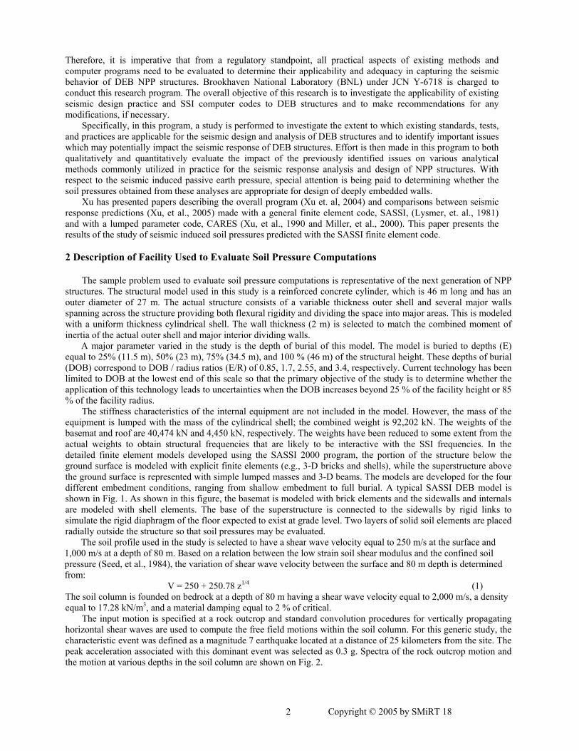
An evaluation of the variation of the pressures with hoop location (θ) is found to be a sine or cosine variation as expected. The variation of the radial stress (normal pressure) with time is first determined. This is done for the head on element (θ = 0) with the element centered at a depth equal to about mid-height of the cylinder. The time at which the highest normal pressure occurs is then used to evaluate the pressure variation with depth. The variation of the three pressure components (Srr, Srt, and Srz) with z is shown on Fig. 3 through 5, respectively, for the four depths of embedment (11.5 m, 23 m, 34.5m, and 46m). The depth is normalized with the embedment depth so that all four cases may be compared. It can be seen that the pressure distributions and magnitudes are very similar for the latter three cases while the 11.5 m DOB results are quite different. Both the radial pressure and tangential shear are almost constant with depth for the three latter cases. The pressure amplitudes are about 25 kN/m2. The tangential shear increases to about 55 kN/m2 near the base for all three cases. The vertical shear for the three cases varies linearly from zero at the surface to about 160 kN/m2 near the base. The 11.5 m DOB case has characteristics which are opposite from the other three cases. The vertical shear is about constant (75 kN/m2) with depth while the normal pressure and tangential shear pressure vary from zero at the basemat to a large value near the surface (320 kN/m2 for the radial pressure and 80 kN/m2 for the tangential shear).
The differences between the 11.5 m case and the other deeper depths of burial cases are likely caused by the large inertial loads in the above ground portion of this structure. Peak accelerations in the above ground portion of the structure for the 11.5 m DOB case reach 0.91 g. The peak accelerations for the 23 m, 34.5 m, and 46 m DOBs reach 0.74 g, 0.43 g, and 0.39g respectively. The 11.5 m case has a much taller structure above grade leading to larger shear and moment loads which are not directly supported by the soil.
The applied shear from the upper cantilever portion of the structure is resisted by the normal pressure and the hoop shear, while the bending moment from the cantilever portion of the structure is resisted by all three pressure components. It can be seen (by virtue of its strong variation with z) that the normal pressure component is primarily due to bending with a small shear component. It is interesting to note that the likely soil horizontal pressure due to dead weight of the soil is one half of the column weight, so that at a depth of 10 m, the horizontal dead weight pressure is about 86 kN/m2 and it would increase linearly with depth. This would indicate that negative pressures would occur for depths less than about 6 m for the 11.5 m depth of burial and about 3 m for the 23 m depth of burial. Non linear effects would not be expected for the deeper depths of burial.
Figure 5 - Variation of Vertical Shear Pressure with Depth
4 Estimation of Nonlinear Effects at the Soil Structure Interface from the SASSI Results
Since SASSI is a linear code, nonlinear effects cannot be specifically considered. However, a comparison of the seismic induced normal pressures with the dead load soil pressures indicates that separation may occur. The soil pressures are examined to determine the extent to which non linear effects may be important. This analysis is done for the 23m depth of burial. Two types of geometric nonlinear effects are considered: separation of the soil and wall, and slipping of the soil along the wall surface. The first will occur when the normal pressure at the interface becomes negative. Since the seismic induced normal pressure varies as a cosine function, the maximum tendency for separation occurs at either the head on location (θ = 0o) or at the opposite location (θ = 180o) depending on which is a tensile pressure. The net pressure at the interface is computed as the dead load pressure minus the maximum seismic pressure. The dead load pressure is assumed to be equal to one half the weight of the soil column above the point of interest. Time histories of net pressure at depths of 1m, 5m, and 11m are shown on Figs. 6 through 8, respectively. Negative net pressures indicate tensile normal pressures and therefore separation. As may be seen significant separation occurs at 1m depth and 5m depths, but very little separation occurs at 11m depth. It should also be noted that separation occurs at many different times so that nonlinear separation effects would be expected to have a significant impact on the seismic response of the facility.
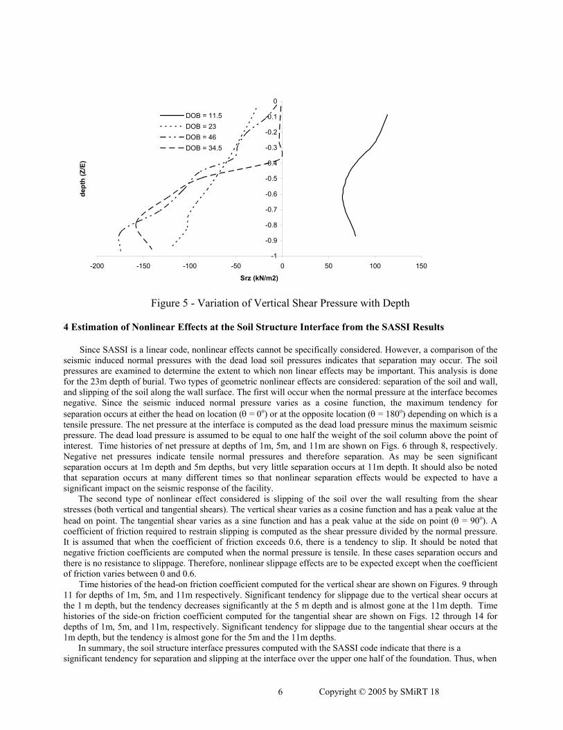
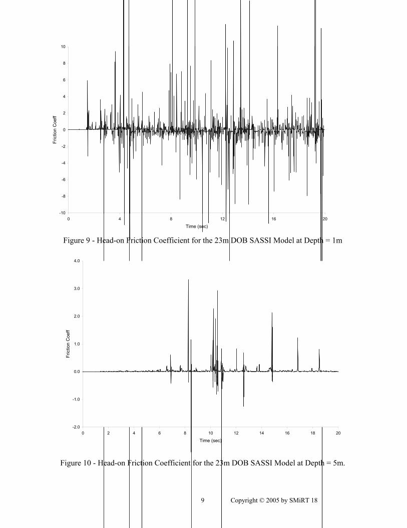
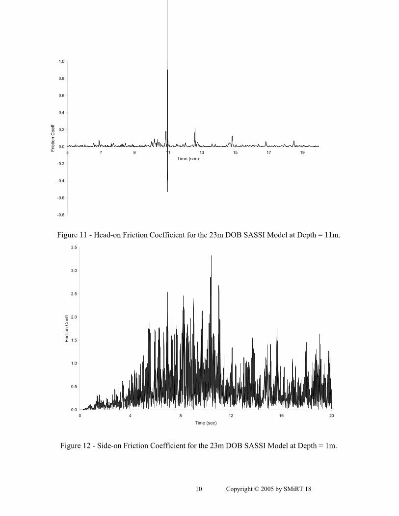
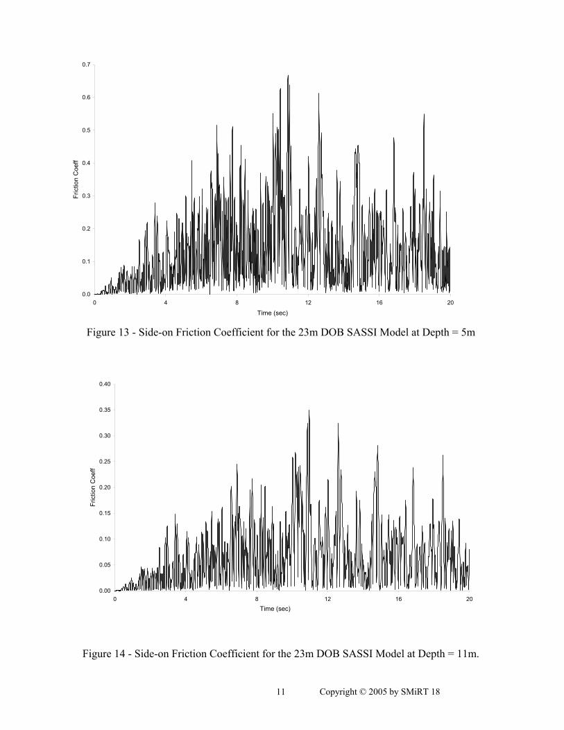
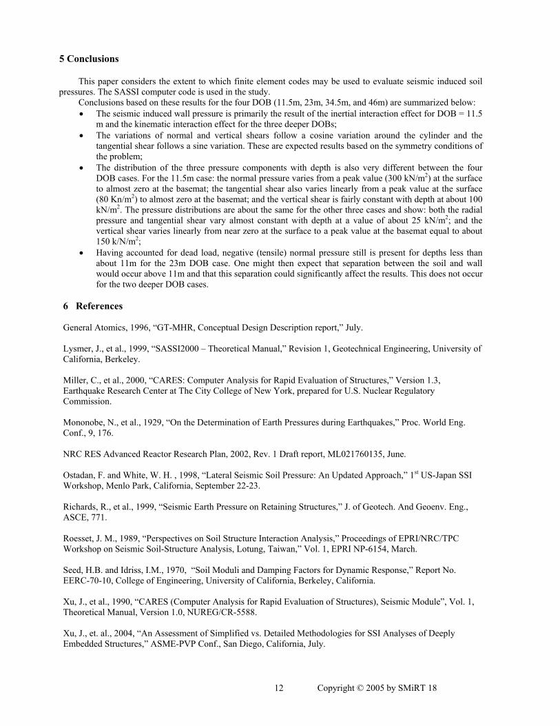
The second type of nonlinear effect considered is slipping of the soil over the wall resulting from the shear stresses (both vertical and tangential shears). The vertical shear varies as a cosine function and has a peak value at the head on point. The tangential shear varies as a sine function and has a peak value at the side on point (θ = 90o). A coefficient of friction required to restrain slipping is computed as the shear pressure divided by the normal pressure. It is assumed that when the coefficient of friction exceeds 0.6, there is a tendency to slip. It should be noted that negative friction coefficients are computed when the normal pressure is tensile. In these cases separation occurs and there is no resistance to slippage. Therefore, nonlinear slippage effects are to be expected except when the coefficient of friction varies between 0 and 0.6.
Time histories of the head-on friction coefficient computed for the vertical shear are shown on Figures. 9 through 11 for depths of 1m, 5m, and 11m respectively. Significant tendency for slippage due to the vertical shear occurs at the 1 m depth, but the tendency decreases significantly at the 5 m depth and is almost gone at the 11m depth. Time histories of the side-on friction coefficient computed for the tangential shear are shown on Figs. 12 through 14 for depths of 1m, 5m, and 11m, respectively. Significant tendency for slippage due to the tangential shear occurs at the 1m depth, but the tendency is almost gone for the 5m and the 11m depths.
In summary, the soil structure interface pressures computed with the SASSI code indicate that there is a significant tendency for separation and slipping at the interface over the upper one half of the foundation. Thus, when
This paper considers the extent to which finite element codes may be used to evaluate seismic induced soil pressures. The SASSI computer code is used in the study.
Conclusions based on these results for the four DOB (11.5m, 23m, 34.5m, and 46m) are summarized below: • The seismic induced wall pressure is primarily the result of the inertial interaction effect for DOB = 11.5
m and the kinematic interaction effect for the three deeper DOBs; • The variations of normal and vertical shears follow a cosine variation around the cylinder and the
tangential shear follows a sine variation. These are expected results based on the symmetry conditions of the problem;
• The distribution of the three pressure components with depth is also very different between the four DOB cases. For the 11.5m case: the normal pressure varies from a peak value (300 kN/m2) at the surface to almost zero at the basemat; the tangential shear also varies linearly from a peak value at the surface (80 Kn/m2) to almost zero at the basemat; and the vertical shear is fairly constant with depth at about 100 kN/m2. The pressure distributions are about the same for the other three cases and show: both the radial pressure and tangential shear vary almost constant with depth at a value of about 25 kN/m2; and the vertical shear varies linearly from near zero at the surface to a peak value at the basemat equal to about 150 k/N/m2;
• Having accounted for dead load, negative (tensile) normal pressure still is present for depths less than about 11m for the 23m DOB case. One might then expect that separation between the soil and wall would occur above 11m and that this separation could significantly affect the results. This does not occur for the two deeper DOB cases.
6 References General Atomics, 1996, “GT-MHR, Conceptual Design Description report,” July. Lysmer, J., et al., 1999, “SASSI2000 – Theoretical Manual,” Revision 1, Geotechnical Engineering, University of California, Berkeley. Miller, C., et al., 2000, “CARES: Computer Analysis for Rapid Evaluation of Structures,” Version 1.3, Earthquake Research Center at The City College of New York, prepared for U.S. Nuclear Regulatory Commission. Mononobe, N., et al., 1929, “On the Determination of Earth Pressures during Earthquakes,” Proc. World Eng. Conf., 9, 176. NRC RES Advanced Reactor Research Plan, 2002, Rev. 1 Draft report, ML021760135, June. Ostadan, F. and White, W. H. , 1998, “Lateral Seismic Soil Pressure: An Updated Approach,” 1st US-Japan SSI Workshop, Menlo Park, California, September 22-23. Richards, R., et al., 1999, “Seismic Earth Pressure on Retaining Structures,” J. of Geotech. And Geoenv. Eng., ASCE, 771. Roesset, J. M., 1989, “Perspectives on Soil Structure Interaction Analysis,” Proceedings of EPRI/NRC/TPC Workshop on Seismic Soil-Structure Analysis, Lotung, Taiwan,” Vol. 1, EPRI NP-6154, March. Seed, H.B. and Idriss, I.M., 1970, “Soil Moduli and Damping Factors for Dynamic Response,” Report No. EERC-70-10, College of Engineering, University of California, Berkeley, California. Xu, J., et al., 1990, “CARES (Computer Analysis for Rapid Evaluation of Structures), Seismic Module”, Vol. 1, Theoretical Manual, Version 1.0, NUREG/CR-5588.
Xu, J., et. al., 2004, “An Assessment of Simplified vs. Detailed Methodologies for SSI Analyses of Deeply Embedded Structures,” ASME-PVP Conf., San Diego, California, July.
Xu, J. et. al., 2005, “Assessment of Seismic Analysis Methodologies for Deeply Embedded NPP Structures,” Proc. Structural Mechanics in Reactor Technology 18, Beijing, China, August. Acknowledgement
This study was supported by the U.S. Nuclear Regulatory Commission, Office of Nuclear Regulatory Research. Their support and encouragement is gratefully recognized. It should be noted that the conclusions drawn in the study represent those of the authors and do not imply acceptance by the USNRC.
Drs. J. Roesset, F. Ostadan, S. Ali and Mr. G. Bagchi acted as peer reviewers on the project. Their advice and comments have been very helpful in carrying out this research.