Clivio et al. Radiation Oncology (2015) 10:97 DOI 10.1186/s13014-015-0381-0
RESEARCH Open Access
Evaluation of the Machine Performance Checkapplication for TrueBeam LinacAlessandro Clivio1, Eugenio Vanetti1, Steven Rose2, Giorgia Nicolini1, Maria F Belosi1, Luca Cozzi3,Christof Baltes2 and Antonella Fogliata3*
Abstract
Background: Machine Performance Check (MPC) is an application to verify geometry and beam performances ofTrueBeam Linacs, through automated checks based on their kV-MV imaging systems. In this study, preliminary testswith MPC were analyzed using all photon beam energies of our TrueBeam, comparing whenever possible with externalindependent checks.
Methods: Data acquisition comprises a series of 39 images (12 with kV and 27 with MV detector) acquired at predefinedpositions without and with the IsoCal phantom in the beam, and with particular MLC pattern settings. MPC performsgeometric and dosimetric checks. The geometric checks intend to test the treatment isocenter size and its coincidencewith imaging devices, the positioning accuracy of the imaging systems, the collimator, the gantry, the jaws, the MLCleaves and the couch position. The dosimetric checks: refer to a reference MV image and give the beam output,uniformity and center change relative to the reference. MPC data were acquired during 10 repetitions ondifferent consecutive days.Alternative independent checks were performed. Geometric: routine mechanical tests, Winston-Lutz test fortreatment isocenter radius. Dosimetric: the 2D array StarCheck (PTW) was used just after the MPC data acquisition.
Results: Results were analyzed for 6, 10, 15 MV flattened, and 6, 10 MV FFF beams. Geometric checks: treatment isocenterwas between 0.31 ± 0.01 mm and 0.42 ± 0.02 mm with MPC, compared to 0.27 ± 0.01 mm averaged on all energies withthe Winston-Lutz test. Coincidence of kV and MV imaging isocenters was within 0.36 ± 0.0 and 0.43 ± 0.06 mm,respectively (0.4 ± 0.1 mm with external tests). Positioning accuracy of MLC was within 0.5 mm; accuracy of jawswas 0.04 ± 0.02, 0.10 ± 0.05, −1.01 ± 0.03, 0.92 ± 0.04 mm for X1, X2, Y1, Y2 jaws, respectively, with MPC. Dosimetric tests:the output stability relative to the baseline was in average 0.15 ± 0.07% for MPC to compare with 0.3 ± 0.2% withthe independent measurement.
Conclusions: MPC proved to be a reliable, fast and easy to use method for checking the machine performanceson both geometric and dosimetric aspects.
BackgroundThe goal of all the quality assurance (QA) programs forlinear accelerators is to guarantee that the machine char-acteristics do not deviate significantly from their baselinevalues acquired at the time of acceptance and commis-sioning [1]. Many publications describe procedures andconditions for testing, as for example the International
* Correspondence: [email protected] and Radiosurgery Department, Humanitas Research Hospital,Milan-Rozzano, ItalyFull list of author information is available at the end of the article
Electrotechnical Commission (IEC) publications [2,3].The main sections of a QA program can be categorizedas: dosimetric, mechanical, imaging, special devices andprocedure, safety. The AAPM Task Group 142 [1] waspublished in 2009 as an update and completion of theAAPM Task Group 40 [4] to give recommendation onall the machine parts, adding the newer ancillary deliverytechnologies (dynamic, intensity modulated IMRT, orstereotactical SRS/SBRT treatments) as well as the im-aging devices that are nowadays an integral part of theLinac: X-ray imaging, photon portal imaging, cone-beam
his is an Open Access article distributed under the terms of the Creativeommons.org/licenses/by/4.0), which permits unrestricted use, distribution, andiginal work is properly credited. The Creative Commons Public Domaing/publicdomain/zero/1.0/) applies to the data made available in this article,
Clivio et al. Radiation Oncology (2015) 10:97 Page 2 of 11
CT. In particular in this report 142 different toleranceshave been recommended, according to the specific usageof the machine: non-IMRT, IMRT, SRS/SBRT. To reportfew specific recommended parameters: for IMRT ma-chines the MLC leaf position accuracy and repeatabilitytolerance is ±1 mm and the MLC spoke shot ≤1 mm ra-dius. The imaging system accuracy should be better than2 mm for non SRS/SBRT machines, decreasing to 1 mmfor Linacs used for stereotactical treatments. The dosi-metric parameters (e.g. flatness and symmetry) shouldstay within ±1% from baseline.The advent in the new Linacs of flattening filter free
modes (FFF beams), not yet covered by the AAPM Re-port 142, having very high dose rates and bell-shapedlateral profiles increased their use for stereotactical treat-ment. Such profiles, so different in shape from the corre-sponding flattened one, faced to the need of evaluatingprofile parameters that cannot be identical to the stand-ard flattened beam parameters, but should keep thesame concepts and could be used in the same way as theanalogous for standard fields [5].The comprehensive modern Linac system, including
the MV electronic portal imaging device, the kV on-board imager allowing also the acquisition of cone-beamCT, shall be checked in terms of coincidence of all theisocenters as part of the QA program. At the same timethose ancillary devices are important instruments thatcould be used to check and evaluate the mutual isocen-ters’ positioning, as well as the constancy of the machineperformances in terms of mechanical, collimating pa-rameters, and also dosimetric constancy for all availablebeams, flattened or unflattened.The concept of the coincidence of all the isocenters
present in the system (mechanical isocenter, treatmentbeam isocenter, kV imaging system isocenter, and MV im-aging system isocenter) has been deeply analyzed and thereare recommendations concerning this subject. For examplethe AAPM Task Group 179 [6] gives strength to the±1 mm tolerance that should be achieved when stereotactictreatments are in place. The same tolerance was suggestedby Yoo et al. [7] for on-board imagers for stereotacticalusage of the Linac. Considering that the usage of such treat-ments is rapidly increasing in the last years due to clinicalreasons, it is becoming more and more important to makeeasily available instruments to apply on regular basis andincluded in the QA program, able to fastly evaluate theLinac performances in terms of accuracy of its main param-eters, geometrical, but also dosimetric for what concernsthe beam stability and constancy.QA methods have been developed to achieve submilli-
metric accuracy for stereotactic linear accelerators, as forexample reported by Grimm et al. [8], mostly based on theWinston-Lutz test, using commercially available phantomand gafchromic films.
QA programs using the aSi-EPID images have been de-veloped for both flattened [9] and unflattened beams [10].Another example of QA program of a linear acceler-
ator, specifically a Varian Unique machine, deeply usingthe imaging devices of the Linac has been published byClivio et al. [11].Specific regulations and recommendations are gener-
ally available in each country, with their own tolerancevalues and frequency of the specific checks. For examplein Switzerland, as in many other countries all over theworld, the Recommendations n. 11 [12] requires a quitelabor intensive program, where the physicist has the fac-ulty to implement different checks once judged appro-priate, even if different from the suggested specific tests.This concept opens the possibility to implement in theroutine checks new comprehensive programs that, withfast and reliable procedure, give many results of differentsections of the entire QA program.The Varian TrueBeam Linacs (Varian Medical Systems,
Inc., Palo Alto, CA) are already equipped with a dedi-cated phantom and associated software, the IsoCal, anautomated geometric calibration system for on-boardimaging and MV imaging systems. Characteristics of theIsoCal are well described in the Gao et al. publication[13], where the authors applied the IsoCal calibrationmethod on the Varian Clinac machines.A step forward is now made available from Varian for
TrueBeam platform version 2.0. It is the Machine Per-formance Check (MPC), an application and process toverify that Linac geometry and beam performances areoperating within system specifications. This is donethrough automated checks based on the kV and MV im-aging systems mounted on the Linac.In the present study, preliminary tests with MPC were
analyzed using all photon beam energies available onour TrueBeam. For each item analysed by the MPC,whenever possible, tests across the same time periodusing our routine procedures and detectors were alsoevaluated, as external independent checks for resultscomparison.
MethodsThe Machine Performance Check (MPC) is a new True-Beam major mode, designed to evaluate the machines geo-metric performance in five minutes. It employs a fullyautomated measurement sequence that uses the kV andMV imaging systems and the proven IsoCal phantom [13].The IsoCal phantom is a hollow cylinder 23 cm in diam-eter and length with 16 tungsten-carbide bearing balls(each 4 mm in diameter). For imager system calibration ituses a collimator plate attached to an accessory slot, hav-ing a steel pin in its center. For MPC implementation, theIsoCal phantom does not use such a collimator plate, andit is mounted to the couch top using a dedicated holder
Clivio et al. Radiation Oncology (2015) 10:97 Page 3 of 11
(Figure 1a). The operator enters into the MPC mode atthe TrueBeam console (Figure 1b), and just initiates theprocedure that takes place automatically. MPC automatic-ally acquires a series of MV and kV images, moving themachine and imaging systems in the pre-defined positions.The two detector panels are positioned at a distance of150 cm from the source. The images are immediatelyprocessed and the results displayed for a quick evaluation,indicating whether the values are within system specifica-tions (Figure 1c). The results can also be reviewed offline(Figure 1d-e), exported and reported.For the present study, a pre-released MPC version
was used, and the sequences were run using the VarianResearch Beam functionality.The predefined acquisitions consist of a set of 39 im-
ages, 12 acquired with kV (XI system) with the IsoCalphantom in the field, 27 with MV (detected on the PortalVision system), of which 20 are with and 7 without theIsoCal phantom in the field. The 39 images are the inputfor the machine performance parameter evaluation.MPC has been here evaluated for the five photon ener-
gies available on our TrueBeam machine: 6, 10, and 15MV and 6, 10 MV FFF.For most of the MPC checks, an independent control
has been performed at the same time of the acquisition ofthe MPC to evaluate the agreement of the two methods.For the independent checks, the here used procedures,phantoms and detectors were those available in the de-partment and routinely used for quality assurance. Theyare not intended to be one-by-one tests relative to the
Figure 1 MPC components: (a) the IsoCal phantom mounted on the coucMPC acquisitions (d) offline review of the parameters and images, (e) offlin
MPC, but want to compare and discuss two differentmethodologies for checking the Linac performances.First the MPC and then the independent checks are
described below.All data, MPC and independent checks, were acquired
for 10 repetitions along a period of 3 weeks for the flat-tened beams, and a subsequent period of 3 weeks for theunflattened beams.
MPC acquisitionsGeometry checksThe geometry checks evaluate the positioning accuracyof the various mechanical axes of the TrueBeam system.An important characteristic of the radiotherapy machineis the position and size of the treatment isocenter. Forthe MV and kV imager systems the important character-istic is the offset of the imager center relative to thetreatment isocenter projection.
IsocenterThe treatment isocenter is determined in MPC using theIsoCal phantom, which is located inside the beam duringthe acquisitions. It is defined as the ideal intersectionpoint of the beam central axes over a full gantryrotation.The beam central axis in MPC is defined, for each gan-
try angle and no IsoCal phantom in place, by the center ofrotation of the MLC (considered as the highest prioritycollimating device), for five collimator rotations, 270°,315°, 0°, 45°, 90° (Figure 2c and d: collimator rotation 45°
h top, (b) the user interface, (c) the quick summary at the end of thee statistics of selected parameters.
a) b) c) d)
e) f) g) h)
Figure 2 Examples among the 39 images needed for MPC evaluation. (a) comb-like pattern for MLC positioning (MV); (b) open beam for beamconstancy (MV); (c) and (d) open field with comb-like MLC pattern for treatment isocenter definition, at two collimator angles (MV); (e) and(f) comb-like MLC pattern with IsoCal phantom for treatment isocenter and gantry position, at different gantry angles (MV); (g) and (h) IsoCal phantomwith different couch positions (kV).
Clivio et al. Radiation Oncology (2015) 10:97 Page 4 of 11
and 90°), according to the procedure described inAdditional file 1, Center of Rotation. The center of ro-tation of the MLC is determined with the edge detec-tion of the MLC leaves (see Additional file 1, EdgeDetection), positioned with a comb-like pattern at al-ternating 4 and 7 cm from the center line.The treatment isocenter is then determined using acqui-
sitions with the IsoCal phantom on eight gantry angles (0°,45°, 90°, 135°, 180°, 225°, 270°, 315°), representative for thefull gantry rotation (Figure 2e and f: gantry angles 0° and45°). The parameters are determined from the position ofthe central beam axis and the expected positions of the 16tungsten BBs of the phantom.
a. Size: The size of the treatment isocenter is definedas the maximum distance of a beam central axisfrom the idealized isocenter.
b. MV and kV Imager Offset: The imager projectionoffset represents the maximum distance of theimager center (MV and kV separately) from theprojection of the treatment isocenter. It is a measureof the correctness of the IsoCal calibration.
CollimationThe positioning accuracy of the whole collimation sys-tem is determined through static fields at gantry position0°. The position of the collimating devices is evaluatedin the acquired images as the point presenting the stee-pest gradient on a line profile perpendicular to the colli-mation edge. The in-plane rotation of the detectorplanes are measured as part of the gantry rotation shots.
MPC can therefore compensate the collimator anglemeasurement for that rotation.
a. MLC (maximal offset, mean offset, individualoffset, bank A/B)
The positioning accuracy of each MLC leaf isdetermined using a static comb-like pattern withalternating leaves. It is measured as the distance ofthe MLC leaf tip from the MLC center line (Figure 2a:the crosses represent the leaf tips and thecorresponding points onto the MLC center linefor calculating the distances). The center line isdefined as the line through the center of rotationof the MLC that is perpendicular to the averageleaf edges at the side (see Additional file 1 – EdgeDetection, for the leaf edge evaluation). The averageand maximum MLC offset, defined as the differencefrom the measured leaf tip position and the nominalvalue, is evaluated per each of the two banks. TheMLC offsets are evaluated for a number of leaf pairsderived by the maximum field size detectable at adistance of 150 cm. For the Millennium-120 MLCused in the current testing phase, the central 40leaf pairs (5 mm width) are evaluated.
b. Jaws (Offset X1/X2/Y1/Y2)Jaw edges are detected on a symmetric 18×18 cm2
field Figure 2b: the crosses represent the edgedetection of the jaw setting, and the lines, fitting theedge detection, are the jaw edges. The central crossis the center of rotation of the MLC. The result ismeasured as the distance of the jaw edges from thecenter of rotation of the MLC. The rationale for the
Clivio et al. Radiation Oncology (2015) 10:97 Page 5 of 11
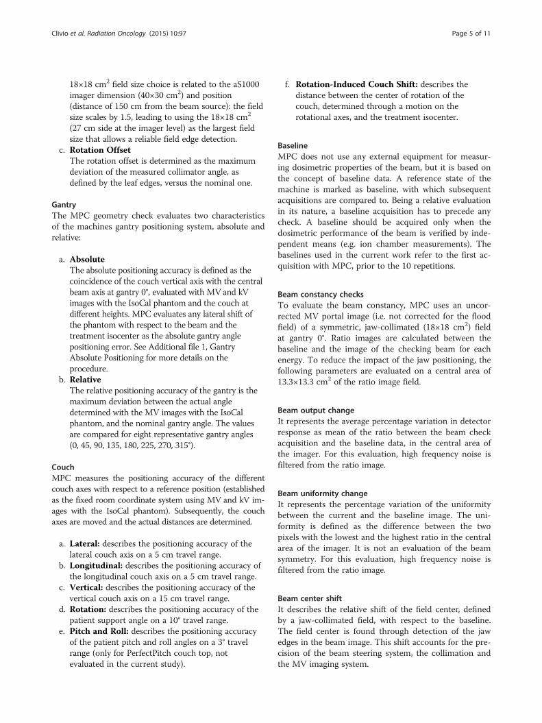
18×18 cm2 field size choice is related to the aS1000imager dimension (40×30 cm2) and position(distance of 150 cm from the beam source): the fieldsize scales by 1.5, leading to using the 18×18 cm2
(27 cm side at the imager level) as the largest fieldsize that allows a reliable field edge detection.
c. Rotation OffsetThe rotation offset is determined as the maximumdeviation of the measured collimator angle, asdefined by the leaf edges, versus the nominal one.
GantryThe MPC geometry check evaluates two characteristicsof the machines gantry positioning system, absolute andrelative:
a. Absolute
The absolute positioning accuracy is defined as thecoincidence of the couch vertical axis with the centralbeam axis at gantry 0°, evaluated with MV and kVimages with the IsoCal phantom and the couch atdifferent heights. MPC evaluates any lateral shift ofthe phantom with respect to the beam and thetreatment isocenter as the absolute gantry anglepositioning error. See Additional file 1, GantryAbsolute Positioning for more details on theprocedure.
b. RelativeThe relative positioning accuracy of the gantry is themaximum deviation between the actual angledetermined with the MV images with the IsoCalphantom, and the nominal gantry angle. The valuesare compared for eight representative gantry angles(0, 45, 90, 135, 180, 225, 270, 315°).
CouchMPC measures the positioning accuracy of the differentcouch axes with respect to a reference position (establishedas the fixed room coordinate system using MV and kV im-ages with the IsoCal phantom). Subsequently, the couchaxes are moved and the actual distances are determined.
a. Lateral: describes the positioning accuracy of thelateral couch axis on a 5 cm travel range.
b. Longitudinal: describes the positioning accuracy ofthe longitudinal couch axis on a 5 cm travel range.
c. Vertical: describes the positioning accuracy of thevertical couch axis on a 15 cm travel range.
d. Rotation: describes the positioning accuracy of thepatient support angle on a 10° travel range.
e. Pitch and Roll: describes the positioning accuracyof the patient pitch and roll angles on a 3° travelrange (only for PerfectPitch couch top, notevaluated in the current study).
f. Rotation-Induced Couch Shift: describes thedistance between the center of rotation of thecouch, determined through a motion on therotational axes, and the treatment isocenter.
BaselineMPC does not use any external equipment for measur-ing dosimetric properties of the beam, but it is based onthe concept of baseline data. A reference state of themachine is marked as baseline, with which subsequentacquisitions are compared to. Being a relative evaluationin its nature, a baseline acquisition has to precede anycheck. A baseline should be acquired only when thedosimetric performance of the beam is verified by inde-pendent means (e.g. ion chamber measurements). Thebaselines used in the current work refer to the first ac-quisition with MPC, prior to the 10 repetitions.
Beam constancy checksTo evaluate the beam constancy, MPC uses an uncor-rected MV portal image (i.e. not corrected for the floodfield) of a symmetric, jaw-collimated (18×18 cm2) fieldat gantry 0°. Ratio images are calculated between thebaseline and the image of the checking beam for eachenergy. To reduce the impact of the jaw positioning, thefollowing parameters are evaluated on a central area of13.3×13.3 cm2 of the ratio image field.
Beam output changeIt represents the average percentage variation in detectorresponse as mean of the ratio between the beam checkacquisition and the baseline data, in the central area ofthe imager. For this evaluation, high frequency noise isfiltered from the ratio image.
Beam uniformity changeIt represents the percentage variation of the uniformitybetween the current and the baseline image. The uni-formity is defined as the difference between the twopixels with the lowest and the highest ratio in the centralarea of the imager. It is not an evaluation of the beamsymmetry. For this evaluation, high frequency noise isfiltered from the ratio image.
Beam center shiftIt describes the relative shift of the field center, definedby a jaw-collimated field, with respect to the baseline.The field center is found through detection of the jawedges in the beam image. This shift accounts for the pre-cision of the beam steering system, the collimation andthe MV imaging system.
Clivio et al. Radiation Oncology (2015) 10:97 Page 6 of 11
Independent checksGeometry checksThe routine checks, according to internal protocols,were performed to evaluate the different geometry tests.
IsocenterThe treatment isocenter was evaluated with a completeWinston-Lutz test [14] for each energy, using the pro-cedure, software and toolkit provided by Varian andcommonly used during machine installations (namedIsoLock). In Figure 3a a field acquired by the IsoLock,showing the set-up for the Winston-Lutz test.The imagers isocenter (kV and MV together) was
checked using the MarkerBlock phantom provided byVarian (Figure 3b), by acquiring two orthogonal MV andkV images. The phantom contains a small, well-definedradio-opaque structure that has to be positioned at iso-center; isocenter location is verified by matching the twoorthogonal images.
CollimationTo evaluate MLC leaf positioning the picket fence testwas evaluated. The test pattern was acquired with theportal imager, where discrepancies ≥0.5 mm can be visu-ally detected thanks to the color scales, as proven withthe same test pattern delivered with intentional errors of0.5 mm.To evaluate the jaw position the PTW StarCheck acquisi-
tions were used for the 10×10 and 20×20 cm2 fields: jawposition was determined according to the field size calcu-lated by the Mephysto software (PTW, Freiburg, Germany).A pre-release version of Mephysto has been used to evalu-ate the field size according to the re-normalization ofunflattened beam profiles, according to Fogliata et al. [5], tohave a check which is compatible between flattenedand unflattened beams. Only the 20×20 cm2 field re-sults are here reported, as more consistent with the18×18 cm2 field size set for MPC checks. The PTWStarCheck is a 2-D array of 527 vented ion chambers
a) b)
Figure 3 Set-up of treatment isocenter tests. (a) A field acquired by the Isotwo orthogonal images acquisition.
with a volume of 0.08 cm3, aligned along the two mainaxes and the two diagonals with 3 mm spatial reso-lution; a dedicated software analyzes the most import-ant parameters of the beam profiles. Detector wasaligned according to the cross-hair (light field). Such apositioning has an intrinsic accuracy (given by theshadow visibility) that could be estimated as 0.5 mm.To question is the choice of the alignment respect tothe cross-hair instead of the light field edges: if thecross-hair is misplaced relative to the beam center, thesingle jaw position check is then affected by that uncer-tainty, that could could reach 1 mm.For the collimator rotation a spirit level was used with
the gantry at 90° and 270° (averaging the positions thatmight differ due to gantry sag), and the collimator set to0, 90, 270°.
GantryFor the mechanical checks an analog spirit level wasused to compare to the digital reading at gantry posi-tions of 0, 90, 270 and 180°.
CouchThe test was performed by moving the couch by 10 cmin the 6 available directions (±lateral, ±longitudinal, and± vertical) and recording the shifts relative to the actualmovement read on a millimetric paper or ruler. For rota-tion, the couch was rotated according to the orthogonallines on the paper (couch at 0, 90, 270°), and the differ-ence relative to the digital readout was recorded.
Beam constancy checksThe PTW StarCheck has been used to independentlycheck the beam constancy. A 10×10 and a 20×20 cm2
field were acquired with the detectors at isocenter dis-tance. The first acquisition, acquired at the same time asthe MPC baseline, was used as reference.
Lock for the Winston-Lutz test; (b) the MarkerBlock phantom for the
Clivio et al. Radiation Oncology (2015) 10:97 Page 7 of 11
Beam outputThe central ion chamber reading, corrected for pressureand temperature, was compared against the reference.
Beam uniformityThe percentage difference of the (Dmax-Dmin)/2 valuesalong the two main axes was referred to the same valuesfrom the reference.
Results and discussionSome examples of the acquired images are shown inFigure 2, with kV and MV maps, with and without theIsoCal in the beam, and the comb-like pattern, accord-ing to the descriptions in the Methods section.For each parameter a threshold value is used by the
MPC software that represents the corresponding True-Beam system specification, and is reported in Tables 1and 2, together with the measured parameter. Valuesexceeding their threshold (or are near to it) ishighlighted by the MPC software in red (or yellow) towarn the user (Figure 1c). For the acquisitions of thepresent study only the 6MV FFF results of three repeti-tions were highlighted in red, and will be discussed later.All other cases passed the checks. The same thresholdvalues were considered also for the independent checks,since they correspond to the machine specifications.
Evaluation accuracyThe accuracy of MPC evaluated parameters includes dataacquisition (measurement accuracy) as well as image pro-cessing (algorithm accuracy). The measurement accuracyis the ceil-rounded standard deviation for each value basedon data from a 6 weeks period of daily measurements.The algorithm accuracy is estimated using synthetic data.Datasets with varying parameters (e.g. shifted phantom,rotated imager) were generated. The mean + 10 times thestandard deviation for each value is rounded to the nexthigher decimal to give the algorithm accuracy for eachvalue. In Table 3 are reported both the algorithm andmeasurement accuracies.The accuracy of the independent measurements was
mostly due to the instrument precision for the geometricchecks, i.e. 0.5 mm for the linear couch movements,1 mm for the collimation settings, 0.5° for the rotationalmovements. The measurement accuracy was here re-ported as standard deviation of the repeated tests. Forbeam constancy checks the accuracy was evaluatedwithin 0.5%.
Geometric checksGeometric checks data are reported in Table 1, as themean values over the 11 acquisitions (10 repetitions andthe baseline); the uncertainty is expressed as one stand-ard deviation on all the acquisitions.
For one acquisition session (including all flattenedbeams), all the couch and gantry group values were un-available, as the necessary markers in the IsoCal phan-tom could not be detected, as they followed out of theexpected area, due to a wrong placement of the IsoCalphantom on its holder for that measurement session,with a shift of more than 5 mm relative to the correctposition. The phantom misplacement was then correctedby the software, and the results were consequently ad-justed. For the subsequent released version of MPC (theversion used in the present study was a pre-released ver-sion), a misplaced phantom won’t influence any mea-sured value as long as all the markers and features couldbe detected. If this won’t be the case, the overall checkresults will be shown as “failed”, meaning that MPC can-not detect all features.As expected, from Table 1 there are no considerable
differences among the energies in the average values ofthe geometric parameters. In particular, we should ex-pect practically identical data for the kV image relatedchecks, as long as kV imager is not influenced by thetreatment beam. The kV imager checks are of primaryimportance, as the kV imager isocenter (offset) is theguarantee of an accurate matching of all patient posi-tioning, 2D or Cone-Beam-CT image based.Coincidence of MV and kV imaging isocenters with re-
spect to the treatment isocenter position resulted wellconsistent between MPC and independent check. Alsothe isocenter size showed to be well consistent betweenMPC and the Winston-Lutz test (with the largest differ-ence of less than 0.15 mm for 6FFF). The collimator ro-tation, gantry and couch positions are well in agreementbetween MPC and routine checks. The Winston-Lutztest with the couch rotation performed for 6 MV onlyshowed a shift of 0.8 mm, to compare with the rotation-induced couch shift of 0.4 mm evaluated by MPC.From all MPC acquisitions the Y jaws parameters
showed an offset for Y1 of about −1 mm for all ener-gies, and +0.9 mm for Y2. This suggested an inaccuratecalibration of the two Y jaws, probably due to a mis-alignment of the cross-hair. To note that the independentchecks did not confirm such offsets; possible concurrentcauses could be the fact that the StarCheck was centeredwith respect to the cross-hair (not to the treatment beamcenter), and the 3 mm resolution of the detector thatcould be not enough to detect small discrepancies. Anadditional check of the cross-hair position with the colli-mator rotation showed a misalignment of the cross-hair of0.5-1 mm, as measurable with a shadow of a line on apiece of paper. With the MPC it was on the contrary pos-sible to clearly and precisely detect such an inaccuracy inthe jaw calibration, that was then corrected. The jaw set-ting resulted consistent for all energies and during thewhole evaluation period, confirming the possible problem
Table 1 Geometric checks: MPC and independent checks for all evaluated parameters, all energies
Clivio et al. Radiation Oncology (2015) 10:97 Page 9 of 11
would be advisable to add in the MPC programme atleast another MLC pattern and another field size, explor-ing a wider range of distances to include a check of lin-earity of the leaf and jaw positioning, possibly on thewidest possible range. The same missing linearity test inMPC is on most of the geometry checks, where a singleshift or rotation is evaluated. The inclusion in the MPCprogramme of the linearity concept, adding at least an-other test point in all geometry checks (possibly coveringthe widest possible range) would add completeness tothe MPC tests as comprehensive machine performancecheck package.
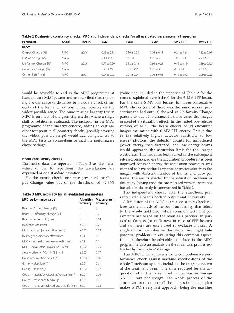
Beam consistency checksDosimetric data are reported in Table 2 as the meanvalues of the 10 repetitions; the uncertainties areexpressed as one standard deviation.For dosimetric checks one case presented the Out-
(value not included in the statistics of Table 2 for thereason explained here below) for the 6 MV FFF beam.For the same 6 MV FFF beams, for three consecutiveMPC checks (one of those was the same session pre-senting the bad output) showed an Uniformity Changeparameter out of tolerance. In those cases the imagespresented a saturation effect. In the tested pre-releaseversion of MPC, the beam checks could encounterimager saturation with 6 MV FFF energy. This is dueto the relatively higher detector sensitivity to lowenergy photons: the detector counts for unflattened(lower energy than flattened) and low energy beamswould approach the saturation limit for the imagerelectronics. This issue has been solved in the subsequentreleased version, where the acquisition procedure has beenimproved: for each energy the acquisition procedure waschanged to have optimal response characteristics from theimager, with different number of frames and dose perframe. The results affected by the saturation problems inthis study (having used the pre-released version) were notincluded in the analysis summarized in Table 2.The independent checks with the StarCheck pre-
sented stable beams both in output and uniformity.A limitation of the MPC beam consistency check re-
lates to the analysis of the beam uniformity, that refersto the whole field area, while common tests and pa-rameters are based on the main axis profiles. In par-ticular, flatness (or unflatness in case of FFF beams)and symmetry are often used to evaluate a beam. Asingle uniformity value on the whole area might hidepotential problems in evaluating this common aspect.It could therefore be advisable to include in the MPCprogramme also an analysis on the main axis profiles ex-tracted by the whole MV image.The MPC is an approach for a comprehensive per-
formance check against machine specifications of thewhole TrueBeam system, including the imaging systemof the treatment beam. The time required for the ac-quisition of all the 39 required images was on average5.6 ± 0.5 min per energy. The whole process of theautomization to acquire all the images in a single planmakes MPC a very fast approach, being the machine
Figure 4 Jaw Offset for all repetitions. Red lines refer to X1 and Y1 jaws, blue lines to X2 and Y2 jaws. Thick lines refer to X1 and X2 jaws, thinlines to Y1 and Y2 jaws. The different line styles belong to different energies (6 and 10 MV, 6 and 10 MV FFF).
Clivio et al. Radiation Oncology (2015) 10:97 Page 10 of 11
occupancy of about 30 minutes to check all the five en-ergies of TrueBeam, even including the time for settingup the IsoCal phantom on its holder. In comparison,the normal routine checks generally are spread over anumber of different tests on the specific items, using dif-ferent phantoms, detectors and set-up, needing much lon-ger time, that could easily last hours, to acquire all thetests on the machine.Evaluating the results compared to independent
checks, the MPC could be easily and safely used foreven daily checks, leaving a deeper quality assurancecontrol for a lower frequency, especially for what con-cerns the dosimetric QA program, also depending onthe specific country regulations. In particular, as an ex-ample, the majority of the requests of the Swiss regula-tions for Linac quality assurance [12] can be easily andfast satisfied with this tool.Point of improvements have been discussed, and
mostly relate to the possibility to add linearity checks.Acquisitions and evaluations over a longer period
would allow to better understand the stability and fullreliability of the dosimetric checks. To consider in anycase that the beam constancy checks cannot be consid-ered as true dosimetric quality assurance controls, beingonly relative to the baseline MV images. MPC is not in-deed intended a machine QA tool and does not replacethe need to perform routine QA. Varian recommendsthat institutions follow accepted QA guidelines.A limitation of the current study is the introduction at
the machine level of known errors on purpose (changingthe output, or the beam symmetry, or the jaw setting to
cite some of the tests), in order to quantify the sensibil-ity of the MPC parameters related to the known errors.This is the subject for the next study.
ConclusionsMPC proved to be a reliable, fast and easy to usemethod for checking the machine performances on bothgeometric and dosimetric aspects and showed to be inagreement with the checks performed with a more con-ventional approach.
Additional file
Additional file 1: MPC acquisition procedures for Center ofRotation, Edge Detection, and Gantry Absolute Positioning.
Competing interestsL. Cozzi acts as Scientific Advisor to Varian Medical Systems and is ClinicalResearch Scientist at Humanitas Research Hospital. All other co-authors haveno competing interests.
Authors’ contributionsAF, LC, CB designed the study; CB, SR provided the data analysis; AC, EV, GN,MFB, LC, AF acquired the data; AF analysed the results; all authors reviewedand approved the final manuscript.
Author details1IOSI, Oncology Institute of Southern Switzerland, Medical Physics Unit,Bellinzona 6504, Switzerland. 2Varian Medical Systems Imaging Laboratory,Baden-Dättwil, Switzerland. 3Radiotherapy and Radiosurgery Department,Humanitas Research Hospital, Milan-Rozzano, Italy.
Clivio et al. Radiation Oncology (2015) 10:97 Page 11 of 11
References1. Klein EE, Hanley J, Bayouth J, Yin F-F, Simon W, Dresser S, et al. Task Group
142 report: quality assurance of medical accelerators. Med Phys.2009;36:4197–212.
2. International Electrotechnical Commission Publication 976. Medical electronaccelerators-functional performance characteristics. 1989.
3. International Electrotechnical Commission Publication 977. Medical electronaccelerators in the range 1 MeV-50 MeV—guidelines for functionalperformance characteristics. 1989.
4. Kutcher GJ, Coia L, Gillin M, Hanson WF, Leibel S, Morton RJ, et al.Comprehensive QA for radiation oncology: report of AAPM RadiationTherapy Committee Task Group 40. Med Phys. 1994;21:581–618.
5. Fogliata A, Garcia R, Knöös T, Nicolini G, Clivio A, Vanetti E, et al. Definitionof parameters for quality assurance of flattening filter free (FFF) photonbeams in radiation therapy. Med Phys. 2012;39:6455–64.
6. Bissonnette JP, Balter P, Dong L, Langen KM, Lovelock DM, Miften M, et al.Quality assurance for image-guided radiation therapy utilizing CT-basedtechnologies: a report of the AAPM TG-179. Med Phys. 2012;39:1946–63.
7. Yoo S, Kim GY, Hammoud R, Elder E, Pawilicki T, Guan H, et al. A qualityassurance program for the on-board imager. Med Phys. 2006;33:4431–47.
8. Grimm J, Grimm SYL, Das IJ, Zhu Y, Yeo I, Xue J, et al. A quality assurancemethod with submillimeter accuracy for stereotactic linear accelerators.J Appl Clin Med Phys. 2011;12:182–98.
9. Nicolini G, Vanetti E, Clivio A, Fogliata A, Boka G, Cozzi L. Testing theportal imager GLAaS algorithm for machine quality assurance. RadiatOncol. 2008;3:14.
10. Nicolini G, Clivio A, Vanetti E, Krauss H, Fenoglietto P, Cozzi L, et al.Evlauation of an aSi-EPID with flattening filter free beams: applicabilityto the GLAaS algorithm for portal dosimetry and first experience forpretreatment QA of RapidArc. Med Phys. 2013;40:111719.
11. Clivio A, Nicolini G, Vanetti E, Fogliata A, Cozzi L. Commissioning andearly experience with a new-generation low-energy linear acceleratorwith advanced delivery and imaging functionalities. Radiat Oncol.2011;6:129.
12. Swiss Society of Radiobiology and Medical Physics: report number 11. Qualitycontrol of medical electron accelerators; 2003. [ISBN 3 908 125 34–0].
13. Gao S, Du W, Balter P, Munro P, Jeung A. Evaluation of IsoCal geometriccalibration system for Varian Linacs equipped with on-board imager andelectronic portal imaging device imaging systems. J Appl Clin Med Phys.2014;15:164–81.
14. Lutz W, Winston KR, Maleki N. A system for stereotactic radiosurgery with alinear accelerator. Int J Radiat Oncol Biol Phys. 1988;14:373–81.
Submit your next manuscript to BioMed Centraland take full advantage of:
• Convenient online submission
• Thorough peer review
• No space constraints or color figure charges
• Immediate publication on acceptance
• Inclusion in PubMed, CAS, Scopus and Google Scholar
• Research which is freely available for redistribution
Submit your manuscript at www.biomedcentral.com/submit