Evaluation of the Lateral Performance of Roof Truss-to-Wall Connections in Light- Frame Wood Systems Andrew DeRenzis Vladimir Kochkin Xiping Wang United States Department of Agriculture Forest Service Forest Products Laboratory General Technical Report FPL–GTR–214
Transcript
Evaluation of the Lateral Performance of Roof Truss-to-Wall Connections in Light-Frame Wood SystemsAndrew DeRenzisVladimir KochkinXiping Wang
United StatesDepartment ofAgriculture
Forest Service
ForestProductsLaboratory
GeneralTechnicalReportFPL–GTR–214
August 2012
DeRenzis, Andrew; Kochkin, Vladimir; Wang, Xiping. 2012. Evaluation of the lateral performance of roof truss-to-wall connections in light-frame wood systems. General Technical Report FPL-GTR-214. Madison, WI: U.S. Department of Agriculture, Forest Service, Forest Products Laboratory. 25 p.
A limited number of free copies of this publication are available to the public from the Forest Products Laboratory, One Gifford Pinchot Drive, Madison, WI 53726–2398. This publication is also available online at www.fpl.fs.fed.us. Laboratory publications are sent to hundreds of libraries in the United States and elsewhere.
The Forest Products Laboratory is maintained in cooperation with the University of Wisconsin.
The use of trade or firm names in this publication is for reader information and does not imply endorsement by the United States Department of Agriculture (USDA) of any product or service.
The USDA prohibits discrimination in all its programs and activities on the basis of race, color, national origin, age, disability, and where applicable, sex, marital status, familial status, parental status, religion, sexual orienta-tion, genetic information, political beliefs, reprisal, or because all or a part of an individual’s income is derived from any public assistance program. (Not all prohibited bases apply to all programs.) Persons with disabilities who require alternative means for communication of program informa-tion (Braille, large print, audiotape, etc.) should contact USDA’s TARGET Center at (202) 720–2600 (voice and TDD). To file a complaint of discrimi-nation, write to USDA, Director, Office of Civil Rights, 1400 Independence Avenue, S.W., Washington, D.C. 20250–9410, or call (800) 795–3272 (voice) or (202) 720–6382 (TDD). USDA is an equal opportunity provider and employer.
AbstractThis testing program was designed to benchmark the performance of traditional roof systems and incrementally improved roof-to-wall systems with the goal of developing connection solutions that are optimized for performance and constructability. Nine full-size roof systems were constructed and tested with various levels and types of heel detailing to measure the lateral performance of the roof-to-wall interface. Our test results indicate that the oriented strandboard (OSB) sheathed high-heel truss detail yields performance comparable to that of the unblocked, low-heel truss configuration that is currently allowed by code. Using OSB sheathing as bracing (without any additional blocking in the heel) can be considered an adequate bracing option in high-heel conditions where the intent is to provide structural performance comparable to that of an unblocked, low-heel truss condition. Results also show that extending the OSB sheathing down and including additional nailing to the top plate of the wall below provide strength and stiffness per-formance superior to that of the solid, intermittent blocking that is currently required in high-wind regions and should be considered a viable truss heel bracing solution to intermit-tent blocking.
AcknowledgmentThis project was funded through a cooperative research agreement between the National Association of Home Builders (NAHB) Research Center and the USDA Forest Service Forest Products Laboratory.
Conversion tableEnglish unit Conversion factor SI unitinch (in.) 25.4 millimeter (mm)foot (ft) 0.3048 meter (m)mile (mi) 1.6093 kilometer (km)square foot (ft2) 0.092903 square meter (m2)pound (lb), mass 0.45359 kilogram (kg)pound (lb), force 4.4482 newton (N)pound per inch (lb/in) 175.13 newton per meter (N/m)pound per foot (lb/ft) 14.594 newton per meter (N/m)
ContentsIntroduction ..........................................................................1Objectives ............................................................................1Code Requirements ..............................................................1Loading Considerations .......................................................2 Wind Considerations ........................................................3 Seismic Considerations ....................................................5Methods and Materials .........................................................5 General .............................................................................5 Specimen Collection ........................................................5 Test Setup and Protocol ....................................................9 Results ................................................................................11Summary and Conclusions ................................................18References ..........................................................................19Appendix A—Summary Load–Displacement Curves .......20Appendix B—Specimen Load–Displacement Curves .......21
Evaluation of the Lateral Performance of Roof Truss-to-Wall Connections in Light-Frame Wood SystemsAndrew DeRenzis, Structural EngineerVladimir Kochkin, DirectorNAHB Research Center, Upper Marlboro, Maryland
Xiping Wang, Research Forest Products TechnologistForest Products Laboratory, Madison, Wisconsin
Conversion tableEnglish unit Conversion factor SI unitinch (in.) 25.4 millimeter (mm)foot (ft) 0.3048 meter (m)mile (mi) 1.6093 kilometer (km)square foot (ft2) 0.092903 square meter (m2)pound (lb), mass 0.45359 kilogram (kg)pound (lb), force 4.4482 newton (N)pound per inch (lb/in) 175.13 newton per meter (N/m)pound per foot (lb/ft) 14.594 newton per meter (N/m)
IntroductionThe 2009 International Residential Code (IRC) includes new requirements for roof-to-wall connections (section R602.10.6) at braced wall panels (ICC 2009). These new requirements were introduced in an effort related to the work of the ICC Ad Hoc Committee on Wall Bracing with the intent to clarify or, where appropriate, reinforce the lat-eral load path between the roof and the braced wall panels of the supporting walls below. (The Ad Hoc Committee on Wall Bracing was established by the International Code Council (ICC) to review the provisions of the IRC related to wall bracing.) Particularly, significant changes were intro-duced for homes with high-heel trusses or deep rafters and for homes located in high hazard areas (wind speeds of 100 mi/h or higher or Seismic Design Category D0, D1, or D2). The requirements include provisions for additional fasten-ing, eave blocking, knee walls, sheathing, or a combination of those elements. These requirements were further clarified and refined for the 2012 IRC.
The new requirements are labor intensive and have implica-tions on cost and time of construction, particularly as high-heel roof configurations become more common as a solution for meeting increasing energy-efficiency standards. The proposed testing program was designed to benchmark the performance of traditional roof systems and incrementally improved roof-to-wall systems with the goal of developing connection solutions that are optimized for performance and constructability.
ObjectivesWith the general focus on the lateral capacity of the roof-to-wall connections in the direction parallel to ridge, specific objectives of this test study were as follows:
1. Establish performance-based limitations on traditional low-heel roof-to-wall connections using hurricane ties and without eave blocking, with three specific goals:
a. Benchmark capacities of the unblocked roof dia-
phragm and unblocked ceiling diaphragms tested as part of a roof assembly
b. Benchmark rotational response of the roof-to-wall connections without eave blocking
c. Understand the system response of the overall roof assembly, including the interaction between roof and ceiling diaphragms
2. Establish performance-based limitations for high-heel roof trusses attached with hurricane ties without eave blocking
3. Measure the performance of high-heel truss systems with intermittent blocking
4. Measure the performance of high-heel truss systems braced against rotation with wood structural panel sheathing attached to the vertical heel member of the truss
Code RequirementsThe new IRC provisions are intended to increase the capac-ity of the heel joint in (1) resisting lateral forces between the roof and the wall and (2) resisting local rotation of the roof members at supports. Table 1 summarizes the 2012 IRC pro-visions for attachment of roof to walls. Figure 1 illustrates the IRC prescriptive detailing options. The special detailing requirements are triggered based on the following:
• Wind speed of 100 mi/h or greater
• Seismic design category D0 and higher
• Heel heights of 9-1/4 and 15-1/4 in.
In the 2012 IRC, eave blocking is the primary method to increase the lateral capacity of the heel joint. The block-ing members transfer shear load to the top plate of the wall below through face nailing or toe-nailing and restrict local rotation of the roof framing members caused by the eccen-tricity of the heel joint. The load from the roof diaphragm is transferred through sheathing connectors into a top chord
General Technical Report FPL–GTR–214
2
member and then into the blocking either through end bear-ing or, if constructed as a blocked diaphragm with the roof sheathing nails penetrating the blocking, through the sheath-ing fasteners.
Loading ConsiderationsThe heel joint at the roof-to-wall interface is subject to wind and seismic forces:
• Lateral forces (wind or seismic)
• Uplift forces (wind; roof uplift forces due to vertical seismic accelerations are not considered in residential design)
• Rotational (overturning) forces (secondary forces due to eccentricity of lateral force)
The scope of this project is limited to investigating the lat-eral load path and the connections and detailing in the IRC for resisting lateral forces in the direction perpendicular to the roof framing members (parallel to the ridge of the roof). Figure 2 shows the loads and the forces in the direc-tion of interest of this study (note that uplift and orthogonal components are not shown intentionally for clarity). The perpendicular-to-ridge direction is not included as it does
not contribute to the lateral load or overturning moment in the direction perpendicular to the trusses.
The effect of the uplift component on the response of roof systems with toe nails or hurricane ties under combined loading has been extensively studied by others (Riley and Sadek 2003, Scoville 2005, Kopp 2010, Simpson Strong-Tie 2010) and therefore is not included in this testing program. In addition, wind uplift forces do not have direct effect on the diaphragm action, cross-grain bending of roof members, truss rotation, and eave blocking performance—the primary areas of this study. Furthermore, significant spatial varia-tions of wind uplift pressure exist across the roof surface, and the wind profiles developed specifically for design purposes (i.e., ASCE 2005) may not be directly applicable to full-scale roof testing for combined loading applications. Their effects should be captured more accurately through full-size wind tunnel testing.
Lateral forces from wind and seismic events are gener-ated through two different mechanisms and imposed on the structure in two different manners. Therefore, the loading type has implications on the selection of appropriate testing procedures. Wind pressures act on the building surfaces, whereas seismic forces act at the location of the masses of the building elements. The following discussion identifies
Table 1—2012 IRC provisions for roof-to-wall attachment Triggers
Nailed connection per IRC table R602.3(1) and partial height blocking nailed to wall top plate
Blocking is only at the braced wall panel
Truss heel joint height 9-1/4 – 15-1/4 in.
Trusses attached per IRC sections R802.10 and R802.11and partial height blocking nailed to wall top plate
Wind at 100 mi/h or greater and SDC D0, D1, D2
Rafter or truss heel joint height up to 15-1/4 in.
Nailed connection per IRC table R602.3(1) and partial height blocking nailed to wall top plate
At all wind speeds and all SDCs
Rafter or truss heel joint exceeds 15-1/4 in.
Options:(1) Blocking at overhang and at top
plate per figure R602.10.6.2(2) (2) Partial height blocking with wall
panels per figure R602.10.6.2(3) (3) Engineered full-height blocking
panels nailed to roof sheathing (blocked diaphragm)
(4) Other engineered methods a SDC, seismic design category.
Evaluation of the Lateral Performance of Roof Truss-to-Wall Connections in Light-Frame Wood Systems
3
unique features of each loading type with respect to the forces acting at the roof-to-wall connections.
Wind ConsiderationsThe ASCE 7 lateral wind load profile in the direction paral-lel to the ridge is shown in Figure 3, with wind pressures acting on both the windward wall surface (positive pres-sure) and leeward wall surface (negative pressure—suction) of the building. For a typical residential floor aspect ratio, the windward pressure is about twice the leeward pressure. These pressures have the same vector direction and their actions are superimposed to develop the total lateral force acting on the building. The wind pressures on the wall surface are transferred through the vertical framing mem-
Figure 2. Wind and seismic loading in the parallel-to-wind direction. (Uplift and orthogonal components are not shown for clarity.)
General Technical Report FPL–GTR–214
4
bers to roof, ceiling, and floor diaphragms and from there to shear walls. This discussion is focused on the forces trans-ferred from the gable end walls into the roof assembly and into the walls below the roof assembly. The forces from ga-ble end wall wind pressures are resisted by the roof sheath-ing diaphragm and the ceiling diaphragm. Figure 4 shows the tributary wind areas associated with each diaphragm. The applicable forces from the top story wall are transferred into the ceiling diaphragm. Typical bracing details at the gable end wall are intended to redistribute the load into the diaphragms and may to some degree affect the distribution of forces between the roof sheathing diaphragm and the ceil-ing diaphragm. This bracing may also impart some amount of rotational restraint to the roof members near the gable ends. Conversely, this restraint contribution would be mini-mal at the interior roof sections.
Eccentricity at the connection depends on the ratio of load delivered to the truss heel through the ceiling to the load delivered through the roof diaphragms, with a higher ratio indicating that there is less load transferred through the roof sheathing and therefore less overturning load at the truss heel. Each diaphragm resists a part of the total load and the ratio of the loads between the two diaphragms var-ies depending upon the roof configuration and location of the gable end wind load resultant. In Example 1 we calcu-late the ratio of load to the two diaphragms for a typical house configuration. For a house with a 5/12 roof pitch and a roof span of 32 ft, the resultant loading ratio of ceiling diaphragm load to roof diaphragm load is 3.2:1; that is, the force transferred through the ceiling diaphragm is 3.2 times greater than the force transferred through the roof diaphragm. For a roof pitch of 7/12 for the same house configuration, the loading ratio is 2.5:1.
Example 1—Calculation of the ratio of wind load to roof diaphragms
Building configuration: Building plan: 32 by 50 ft Two stories Story height: 9 ft Roof pitch: 5/12 Mean roof height: 25 ft Gable end roof Wind parallel to ridge Overhang: 2 ftBasic wind speed: 140 mi/h (ASCE 7–10)Exposure: BWind pressure: 30 lb/ft2 (rounded for simplicity of calculations)Gable end wall forces: Total gable end area: (distribution from top of wall to ridge) × (roof width) × 0.5 = [((32 ft ÷ 2) + 2 ft)(5/12)] × (32 ft + 4 ft) × (0.5) = 135 ft2
Force into each diaphragm from gable end: (simply supported, vertical framing members spanning between two diaphragms) (135 ft2) × (30 lb/ft2) × (0.5) = 2,025 lb
Second-story wall forces:Tributary wall area of the top story: (building width) × (wall height) × 0.5 = (32 ft) × (9 ft) × (0.5) = 144 ft2Force into ceiling diaphragm from top story wall: (144 ft2) × (30 lb/ft2) = 4,320 lb
Ratio of roof diaphragm load to ceiling diaphragm load: 1:3.2
The same example for a roof pitch of 7/12 results in: 1:2.5
1
2
34
5
6
1E
2E
3E4E
5E
6E
Θ
Winddirection
Windward corner
a 2a
(a) Directional procedure
Wind
PlanL
B
Elevation
qhGCp
qhGCp
qhGCp
qzGCp Z
L
B
h
qhGCp
qhGCp
qhGCp
qzGCp
(b) Envelope procedure
Figure 3. ASCE 7 wind loading profile.
Evaluation of the Lateral Performance of Roof Truss-to-Wall Connections in Light-Frame Wood Systems
5
Example 2—Calculation of the eccentricity of seismic load
Building configuration: Building plan: 32 by 50 ft Two stories Story height: 9 ft Roof pitch: 5/12 Mean roof height: 25 ft Gable end roof Acceleration parallel to ridgeOverhang: 2 ftRoof dead load: 15 lb/ft2Wall dead load: 9 lb/ft2
Roof weight: (15 lb/ft2) × (32 ft + 2 ft) × (50 ft) = 25,500 lb (half overhang is used at 15 lb/ft2 dead load)Wall weight: (9 lb/ft2) × (32 ft) × (9 ft ÷ 2) × (2 walls) = 2,592 lb
Ratio of roof diaphragm load to ceiling diaphragm load: 1:1
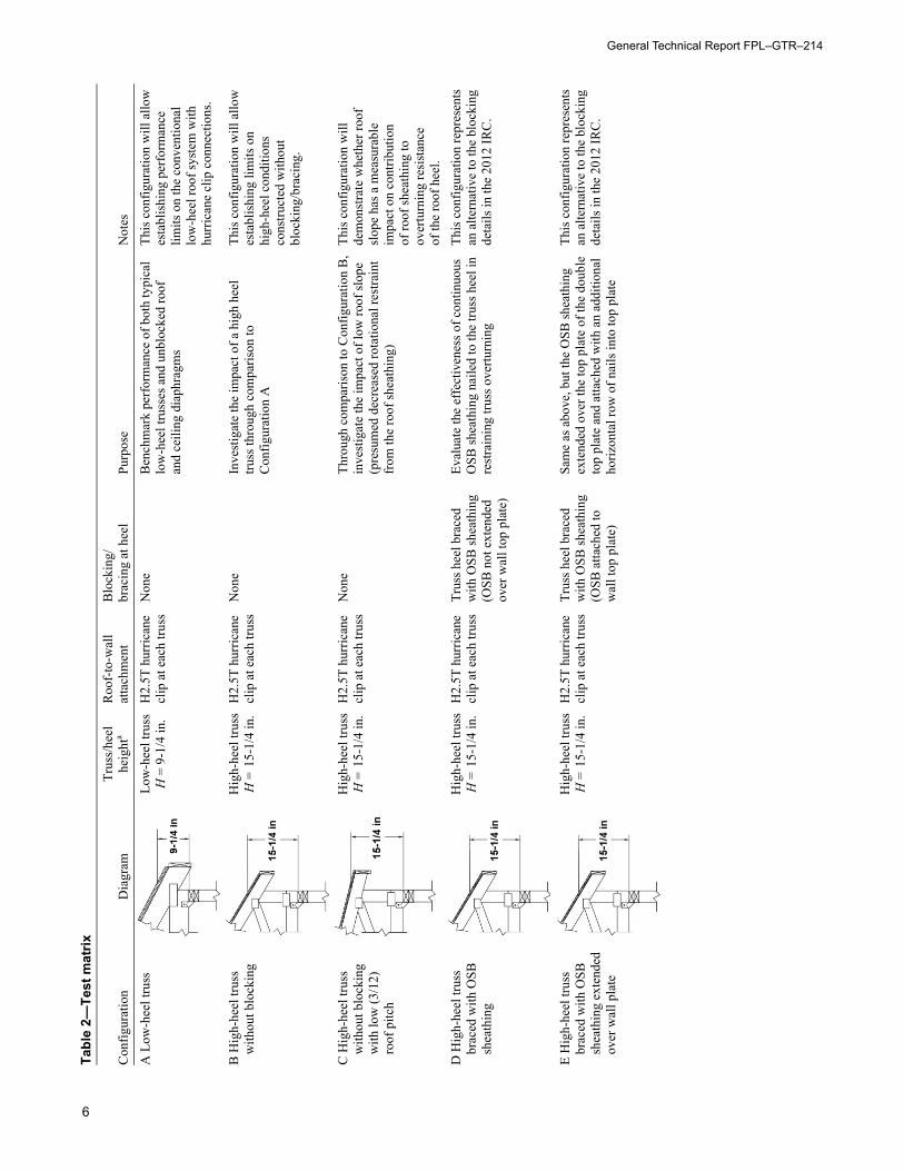
blocking. A purpose statement with explanation is provided for each configuration. Nine full-size roof systems were test-ed with various levels and types of heel detailing to measure the lateral performance of the roof-to-wall interface.
Specimen CollectionTable 3 summarizes materials and methods used in construc-tion of the specimens, and Table 4 provides details of the various blocking/bracing methods.
Each specimen was constructed with five 24-ft-span wood trusses spaced at 24 in. on center (o.c.), with the overall size of the full roof system at 24 ft wide by 8 ft deep with ad-ditional 16-in.-long overhangs on each side (Fig. 5). Trusses were supported at the heel by 4-ft-high light-frame knee walls anchored to the laboratory’s strong floor. Strength and stiffness of the knee walls were sufficiently higher than those of the roof system to prevent any significant
Seismic ConsiderationsUnlike wind pressures, which are imposed on the outside shell of the structure, seismic load is distributed throughout the building based on the mass of the elements. The eccen-tricity at the truss heel connection is still governed, however, by the ratio of loading between the two diaphragms. The total force resisted by the roof-to-wall connections is associ-ated with (1) the mass of the roof diaphragm, (2) the mass of the ceiling diaphragm, and (3) the mass of half the height of the top story walls below the roof gable end. The walls supporting the roof eave do not directly contribute to the overturning forces at the roof heel.
The distribution of the weight between the two diaphragms is close to symmetric with the weight of the sheathing ma-terials (oriented strandboard (OSB) and gypsum) and the primary framing members being located around the perim-eter of the roof triangle. The weight of the shingles is attrib-uted to the top chords, and the weight of insulation, eaves, overhangs, and any mechanical equipment is attributed to the bottom of the roof assembly. Example 2 shows that the top story walls contribute only 10% to the total lateral force resisted by the ceiling diaphragm, and that contribu-tion is ignored for the purposes of this study. Therefore, the resultant loading ratio of ceiling diaphragm load to roof dia-phragm load is about 1:1; that is, half the total force is trans-ferred through the ceiling diaphragm and half is transferred through the roof sheathing diaphragm.
Methods and MaterialsGeneralTesting was conducted at the NAHB Research Center labo-ratory facility located in Upper Marlboro, Maryland. All specimens were constructed in the laboratory, and all con-struction materials were purchased from local suppliers.
Table 2 shows a test matrix summarizing specimen configu-rations, including connections, truss–heel height, and
Tributary load torood diaphragm
Tirbutary load toceiling diaphragm
Figure 4. Tributary area of wind loads.
General Technical Report FPL–GTR–214
6
Tabl
e 2—
Test
mat
rix
Con
figur
atio
n D
iagr
am
Trus
s/he
el
heig
hta
Roo
f-to
-wal
lat
tach
men
t B
lock
ing/
brac
ing
at h
eel
Purp
ose
Not
es
A L
ow-h
eel t
russ
Lo
w-h
eel t
russ
H =
9-1
/4 in
. H
2.5T
hur
rican
e cl
ip a
t eac
h tru
ss
Non
eB
ench
mar
k pe
rfor
man
ce o
f bot
h ty
pica
l lo
w-h
eel t
russ
es a
nd u
nblo
cked
roof
an
d ce
iling
dia
phra
gms
This
con
figur
atio
n w
ill a
llow
esta
blis
hing
per
form
ance
lim
its o
n th
e co
nven
tiona
l lo
w-h
eel r
oof s
yste
m w
ith
hurr
ican
e cl
ip c
onne
ctio
ns.
B H
igh-
heel
trus
s w
ithou
t blo
ckin
g H
igh-
heel
trus
sH
= 1
5-1/
4 in
. H
2.5T
hur
rican
e cl
ip a
t eac
h tru
ss
Non
eIn
vest
igat
e th
e im
pact
of a
hig
h he
el
truss
thro
ugh
com
paris
on to
C
onfig
urat
ion
A
This
con
figur
atio
n w
ill a
llow
esta
blis
hing
lim
its o
n hi
gh-h
eel c
ondi
tions
co
nstru
cted
with
out
bloc
king
/bra
cing
.
C H
igh-
heel
trus
s w
ithou
t blo
ckin
g w
ith lo
w (3
/12)
ro
of p
itch
Hig
h-he
el tr
uss
H =
15-
1/4
in.
H2.
5T h
urric
ane
clip
at e
ach
truss
N
one
Thro
ugh
com
paris
on to
Con
figur
atio
n B
,in
vest
igat
e th
e im
pact
of l
ow ro
of sl
ope
(pre
sum
ed d
ecre
ased
rota
tiona
l res
train
t fr
om th
e ro
of sh
eath
ing)
This
con
figur
atio
n w
ill
dem
onst
rate
whe
ther
roof
sl
ope
has a
mea
sura
ble
impa
ct o
n co
ntrib
utio
n of
roof
shea
thin
g to
ov
ertu
rnin
g re
sist
ance
of
the
roof
hee
l. D
Hig
h-he
el tr
uss
brac
ed w
ith O
SB
shea
thin
g
Hig
h-he
el tr
uss
H =
15-
1/4
in.
H2.
5T h
urric
ane
clip
at e
ach
truss
Tr
uss h
eel b
race
d w
ith O
SB sh
eath
ing
(OSB
not
ext
ende
d ov
er w
all t
op p
late
)
Eval
uate
the
effe
ctiv
enes
s of c
ontin
uous
O
SB sh
eath
ing
naile
d to
the
truss
hee
l in
rest
rain
ing
truss
ove
rturn
ing
This
con
figur
atio
n re
pres
ents
an a
ltern
ativ
e to
the
bloc
king
deta
ils in
the
2012
IRC
.
E H
igh-
heel
trus
s br
aced
with
OSB
sh
eath
ing
exte
nded
ov
er w
all p
late
Hig
h-he
el tr
uss
H =
15-
1/4
in.
H2.
5T h
urric
ane
clip
at e
ach
truss
Tr
uss h
eel b
race
d w
ith O
SB sh
eath
ing
(OSB
atta
ched
to
wal
l top
pla
te)
Sam
e as
abo
ve, b
ut th
e O
SB sh
eath
ing
exte
nded
ove
r the
top
plat
e of
the
doub
leto
p pl
ate
and
atta
ched
with
an
addi
tiona
lho
rizon
tal r
ow o
f nai
ls in
to to
p pl
ate
This
con
figur
atio
n re
pres
ents
an a
ltern
ativ
e to
the
bloc
king
deta
ils in
the
2012
IRC
.
Evaluation of the Lateral Performance of Roof Truss-to-Wall Connections in Light-Frame Wood Systems
7
Tabl
e 2—
Test
mat
rix—
con.
Con
figur
atio
n D
iagr
am
Trus
s/he
el
heig
hta
Roo
f-to
-wal
lat
tach
men
t B
lock
ing/
brac
ing
at h
eel
Purp
ose
Not
esF
Hig
h-he
el tr
uss
with
blo
ckin
g at
inte
rmitt
ent
loca
tions
Hig
h-he
el tr
uss
H =
15-
1/4
in.
H2.
5T h
urric
ane
clip
at e
ach
truss
Pa
rtial
hei
ght b
lock
ing
(25%
of w
all l
engt
h)
Eval
uate
the
cond
ition
whe
re b
lock
ing
is in
stal
led
in a
n in
term
itten
t co
nfig
urat
ion
(this
con
figur
atio
n re
pres
ents
a sc
enar
io w
here
blo
ckin
g is
inst
alle
d at
bra
ced
wal
l pan
els o
nly)
This
con
figur
atio
n is
in
tend
ed to
eva
luat
e th
e us
e of
inte
rmitt
ent c
ompa
red
with
con
tinuo
us b
lock
ing.
G H
igh-
heel
trus
s w
ith b
lock
ing
at
ever
y ot
her b
ay
Hig
h-he
el tr
uss
H =
15-
1/4
in.
H2.
5T h
urric
ane
clip
at e
ach
truss
Pa
rtial
hei
ght b
lock
ing
(50%
of w
all l
engt
h)
Eval
uate
the
cond
ition
whe
re b
lock
ing
is in
stal
led
at e
very
oth
er b
ay
This
con
figur
atio
n is
in
tend
ed to
eva
luat
e th
e us
e of
inte
rmitt
ent c
ompa
red
with
con
tinuo
us b
lock
ing.
H H
igh-
heel
trus
s w
ith b
race
d w
ebs
Low
-hee
l tru
ssH
= 1
5-1/
4 in
. H
2.5T
hur
rican
e cl
ip a
t eac
h tru
ss
Dia
gona
l bra
cing
of
trus
s web
s Ev
alua
te th
e ef
fect
iven
ess o
f web
br
acin
g in
rest
rain
ing
truss
ov
ertu
rnin
g at
the
heel
This
con
figur
atio
n is
in
tend
ed to
eva
luat
e th
e co
ntrib
utio
n of
web
br
acin
g th
at m
ay a
lread
y be
pre
sent
in th
e ro
of
asse
mbl
y in
resi
stin
g ot
her f
orce
s. I H
igh-
heel
trus
s br
aced
with
OSB
sh
eath
ing
and
a re
info
rced
cei
ling
diap
hrag
m
Hig
h-he
el tr
uss
H =
15-
1/4
in.
H2.
5T h
urric
ane
clip
at e
ach
truss
Sh
eath
ing
exte
nded
do
wn
to c
aptu
re
top
plat
e
Eval
uate
per
form
ance
of C
onfig
urat
ion
E bl
ocki
ng m
etho
d w
ith re
info
rced
gy
psum
dia
phra
gm
The
ceili
ng d
iaph
ragm
is
rein
forc
ed in
an
atte
mpt
to
forc
e fa
ilure
at t
he tr
uss
heel
con
nect
ion
inst
ead
of th
e gy
psum
dia
phra
gm.
This
test
is in
tend
ed
to v
alid
ate
the
perf
orm
ance
of
OSB
bra
cing
det
ail
at h
ighe
r dia
phra
gm
capa
citie
s (i.e
., hi
gher
ov
ertu
rnin
g fo
rce
at th
e he
el).
a All
truss
es a
re sp
aced
24
in. o
n ce
nter
(o.c
.).
General Technical Report FPL–GTR–214
8
Table 3—Specimen materials and construction Materials Construction Roof span 24 ft (plus 16-in. overhang on each end) Roof length 8 ft Roof pitch 7/12 or 3/12 per test matrix (Table 2) Roof framing members Metal-plate-connected wood trusses fabricated with No. 2 southern yellow pine
lumber; heel heights either 9-1/4 or 15-1/4 in. per test matrix (Table 2) Truss spacing 24 in. o.c.a
Truss-to-wall connections Simpson Strong-Tie H2.5T hurricane truss clips connecting each truss and both top plate members with a total of 10 8d common (2-1/2- by 0.131-in.) nails (5 nails per each truss)
Fascia board 1- by 6-in. nominal lumber face nailed to each truss end with two 8d common (2-1/2- by 0.131-in.) nails
Roof sheathing materials 7/16-in.-thick OSB sheathing installed perpendicular to framing member with steel edge clips and unblocked edges parallel to ridge
Roof sheathing fasteners 8d common (22-1/2- by 0.131-in.) at 6 in. o.c. on panel perimeter and 12 in. o.c.in panel field
Ceiling material 1/2-in.-thick gypsum panels installed perpendicular to truss bottom chord members, joints taped and mudded
Ceiling fasteners 1-5/8-in. Type W drywall screws: Configurations A to H—12 in. o.c. with first rows of fasteners 8 in. in from side walls (i.e., floating edges) Configuration I—8 in. o.c. with first rows of fasteners 8 in. in from side walls (i.e., floating edges)
Ceiling boundary chord Configuration I only—2- by 4-in. nominal double chord member face nailed together with 10d (3- by 0.128-in.) nails at 24 in. o.c. and 8 16d (3-1/2- by 0.135-in.) nails in spliced sections; outer trusses toe nailed to double chord member with 8d box (2-1/2- by 0.113-in.) nails at 6 in. o.c.
Knee wall framing (including top plates)
2- by 4-in. nominal SPF No. 2 grade lumber
Knee wall sheathing 7/16-in.-thick OSB sheathing attached with 8d common (2-1/2- by 0.131-in.) nails at 3 in. o.c. on panel perimeter and 12 in. o.c. in panel field
a o.c., on center.
Table 4—Truss blocking/bracing construction details Configuration Blocking/bracing Connection High heel braced with OSB 7/16-in. OSB, 10-1/2 in. wide by 8 ft long Face nailed to each truss heel with 3 8d common
(2-1/2- by 0.131-in.) nails High heel braced with OSB attached to top plate
7/16-in. OSB, 11-1/2 in. wide by 8 ft long Face nailed to each truss heel with 3 8d common (2-1/2- by 0.131-in.) nails; face nailed to top member of double top plate with 8d common (2-1/2- by 0.131-in.) nails at 6 in. o.c.a
High heel with 25% blocking 1-1/8-in.-thick by 14-in.-high iLevel rim board contact fit between trusses
End nailed to trusses with 2 16d box (3-1/2- by 0.135-in.) nails; toe nailed to top plate with 5 8d box (2-3/8- by 0.113-in.) nails at 6 in. o.c.
High heel with 50% blocking 1-1/8-in.-thick by 14-in.-high iLevel rim board contact fit between trusses
End nailed to trusses with 2 16d box (3-1/2- by 0.135-in.) nails; toe nailed to top plate with 5 8d box (2-3/8- by 0.113-in.) nails at 6 in. o.c.
High heel with diagonal web bracing
2- by 4-in. nominal SPF No. 2 grade lumber
Face nailed to truss web with 2 8d common (2-1/2- by0.131-in.) nails
a o.c., on center.
Evaluation of the Lateral Performance of Roof Truss-to-Wall Connections in Light-Frame Wood Systems
9
deformations in the supporting structure. Roof trusses were attached to the double top plate of the knee wall in accor-dance with fastening schedules specified in Tables 3 and 4. The double top plate was attached to the knee wall framing with bolts and was replaced after each test.
For all tests, truss bottom chords were connected to the top plates of the supporting knee walls using H2.5T hurricane clips. Clips on both ends of a truss were installed on the same face of that truss; the installation face was alternated between adjacent trusses (Fig. 5) to eliminate any direction-al bias in the resistance behavior of the clips. A continuous 1- by 6-in. nominal fascia board was installed on both sides of the specimens.
The roof sheathing was installed perpendicular to the truss top chord members with a staggered panel layout. Metal sheathing clips were installed on the unblocked edges of each panel at 24 in. o.c. between the framing members. A 2-in.-wide roof vent was provided at the ridge (at 1 in. on each side of the ridge) such that bearing of panel edges did not occur during testing.
The ceiling gypsum panels were installed perpendicular to the truss bottom chord members, and the first row of fasten-ers was located approximately 8 in. from each knee wall (that is, floating edges) in accordance with the Gypsum Association’s Application and Finishing of Gypsum Panel Products (GA-216-2010) (Gypsum Association 2010). All interior gypsum panel joints were taped and mudded, and no finishing was done at the interface of the ceiling and the knee walls. The ceiling diaphragm of Specimen I was rein-forced at the front and back trusses with a double top plate boundary member and 2-in. nominal nailing member (Fig. 6f). The fastener spacing of the ceiling diaphragm in
Specimen I was also reduced from 12 to 8 in. o.c. to in-crease the diaphragm’s capacity. (Specimens A through H were constructed without these additional boundary/chord members.)
Figure 6 provides details of the various blocking methods evaluated in this testing program. All blocking methods were in addition to the typical roof specimen described ear-lier in this section.
Test Setup and ProtocolFigure 7 shows the test setup including the specimen, load-ing brace, and instrumentation. Figure 8 provides a photo-graph of the test setup, reaction frame, and data acquisition system.
Load was applied to the specimen through permanent truss bracing (2- by 6-in. nominal Southern Pine, No. 2 grade lumber) attached at mid-height of the center vertical web member of each truss. The intent of using a pair of typical permanent truss braces was to minimize the restraints im-posed on the specimen by the loading apparatus by applying the load through members that are typically present in truss roof assemblies. Load was applied at a mid-height perma-nent bracing location that yielded a 1:1 roof diaphragm to ceiling diaphragm loading ratio (i.e., the loading ratio caused by a seismic loading scenario). This loading condi-tion results in the highest eccentricity at the heel such that observations on the effectiveness of the tested heel blocking/bracing options are appropriate for a broad range of applica-tions.
Each center vertical truss web member was reinforced with a double 2- by 8-in. nominal vertical member to prevent weak-axis bending failure of the web. Each permanent
Figure 5. Specimen construction.
General Technical Report FPL–GTR–214
10
Figure 6. Truss-blocking details: (a) high heel with OSB; (b) high heel with OSB to plate; (c) high heel with 25% blocking; (d) high heel with 50% blocking; (e) high heel with diagonal web bracing; (f) high heel with OSB to plate and reinforced ceiling diaphragm (OSB not shown for clarity).
(a) (b)
(e)
(f)
(c) (d)
Evaluation of the Lateral Performance of Roof Truss-to-Wall Connections in Light-Frame Wood Systems
11
bracing member was attached to the vertical reinforcing member with a single 4-1/2- by 1/2-in. lag bolt to provide sufficient load transfer with minimal rotational restraint.
The loading brace members were loaded in tension using a computer-controlled hydraulic cylinder mounted to a steel reaction frame. The reaction frame was attached to the laboratory structural floor. Load was applied monotonically in tension at a constant displacement rate of 0.06 in/min to allow for sufficient visual observations throughout the test and was measured using an electronic load cell installed between the cylinder and the loading bracket. Displacement was continued until failure, defined as a 20% drop in load from the peak.
Displacements of the roof system relative to either the sup-porting knee walls or the laboratory structural floor were measured using electronic linear motion position transduc-ers (LMPTs) at several locations:
• Ceiling diaphragm at mid-span of the roof/truss assembly
• Top and bottom of the heel on the first/front truss at both ends
• Top and bottom of the heel on the fourth truss at both ends (Specimens F and G only)
• The bottom of the heel on the fifth/rearmost truss
Displacement of the top of the supporting knee walls was also measured relative to the structural floor using LMPTs. Finally, displacement at the peak of the roof/truss assembly was measured relative to the steel reaction frame using a string potentiometer. Uplift at the rear of the specimen was not measured; initial tests showed that uplift was minimal because of the vertical restraint provided by the hurricane clip connections.
All load and displacement measurements were recorded using an electronic data acquisition system.
ResultsResults of the testing are summarized in Table 5, includ-ing peak load reached by the roof assembly and unit peak capacity of the truss-to-wall connections. Table 5 also in-cludes initial stiffness values for each specimen determined from the displacement at the top of the truss heel (TOH) measured relative to the top plate. The initial stiffness was calculated at a 760-lb load level, selected as an approximate representation of the linear range for performance com-parison between systems tested in this study. Figures 9 and 10 compare peak capacity and stiffness, respectively, for various specimens tested. (Fig. 10 shows specimen load–displacement curves where displacement was measured at the peak of the specimen, not at the top of the truss heel.) See Appendix A for summary figures of load–displacement curves measured at the TOH location. Appendix B provides several load–displacement curves for each individual speci-men measured at various locations on the specimen, includ-ing the midpoint of both the top and bottom chords of
Figure 7. Test setup and instrumentation.
Figure 8. Test setup.
General Technical Report FPL–GTR–214
12
Table 5—Test results
Configuration Diagram Peak load
(lb)
Peak loadper truss
connection(lb)
Unit peak capacity (lb/ft)a
Initial stiffness (lb/in)b
A Low-heel truss 5,140 514 255 8,828
B High-heel truss without blocking
3,525 352 175 4,432
C High-heel truss without blocking with low (3/12) roof pitch
3,780 378 190 3,950
D High-heel truss braced with OSB sheathing
4,344 434 215 10,395
E High-heel truss braced with OSB sheathing extended over wall plate
4,755 475 240 32,224
F High-heel truss with blocking at intermittent locations
3,988 399 200 23,548
G High-heel truss with blocking at every other bay
4,520 452 225 26,581
Evaluation of the Lateral Performance of Roof Truss-to-Wall Connections in Light-Frame Wood Systems
13
Truss 1, the left and right TOH of Truss 1, and where appli-cable, the left and right TOH of Truss 4.
A discussion of each individual test is provided in this sec-tion, including discussion of peak capacities and initial stiff-ness relative to baselines (where applicable) and observed governing failure modes. Visual observations regarding rotation of the trusses are noted as part of the failure mode discussion. Additional analysis of rotation/displacement of the truss heels and comparisons of peak capacities to typical
design loads are summarized and presented at the end of this section.
Specimens A to C were intended to establish baseline capac-ities and performance characteristics for low- and high-heel roof systems without blocking or bracing the truss heel. The low-heel truss configuration (Specimen A) represents the highest allowable heel height by code that does not require blocking. Specimen A achieved a peak load of 5,140 lb (peak unit capacity of 255 lb/ft) and initial stiffness of
Figure 9. Comparison of peak capacities per truss connection.
Table 5—Test results—con.
Configuration Diagram Peak load
(lb)
Peak loadper truss
connection(lb)
Unit peak capacity (lb/ft)a
Initial stiffness (lb/in)b
H High-heel truss with braced webs
3,633 363 180 5,469
I High-heel truss braced with OSB sheathing and a reinforced ceiling diaphragm
6,794 679 340 41,362
aUnit peak capacity is calculated by dividing the peak load per connection by the typical 2-ft truss spacing (i.e., the tributary area of a typical truss). bInitial stiffness measured at roof peak of specimen.
General Technical Report FPL–GTR–214
14
8,828 lb/in. Failure of Specimen A included initial fastener tear-through at the outer ends of the ceiling diaphragm near the knee walls followed by complete failure of the fasteners in the center gypsum panel (Figs. 11 and 12). Only minor rotation of the truss heels was observed during testing as well as minor rotation and buckling of the hurricane clips (Fig. 13). Minor displacement of the truss top chord rela-tive to the bottom chord at the heel joint was also observed, along with slight deformation of the metal connector plate at the heel joint (Fig. 14).
Specimen B represents the second trigger height specified by code (see Table 1). Trusses with heel heights between the 9-1/4-in. height of Specimen A and the 15-1/4-in. height of Specimen B are currently required to have solid blocking between each truss when framed over top of a braced wall panel. Specimen B omitted this blocking in order to com-pare the effect of higher heel height on roof system capac-ity with the Specimen A results and to establish a baseline performance benchmark against which the various blocking/bracing details evaluated in this study could be measured. Specimen B reached a peak load of 3,525 lb (peak unit ca-pacity of 175 lb/ft) and initial stiffness of 4,432 lb/in. This is a 33% drop in capacity and a 50% drop in initial stiffness from the results of Specimen A, illustrating the effect of increased heel height on the global response for a system without blocking. The primary failure mode was again tear-through of the gypsum panel fasteners at both ends of the specimen near the knee walls. All the gypsum panels, how-ever, remained intact and attached to the framing members throughout the test. Significant rotation of the trusses at the heel connections and minor buckling of the hurricane clips were also observed.
Specimen C was designed to evaluate the effect of a lower roof slope on the performance of the truss-to-wall connec-tions. Specimen C was similar in construction to Specimen B and reached a peak capacity of 3,780 lb (peak unit capac-ity of 190 lb/ft) and initial stiffness of 3,950 lb/in. Specimen C exhibited similar damage and failure modes as Specimen B (that is, gypsum fastener tear-through, significant rotation observed at the truss heel). Additional damage was also ob-served in the form of buckled hurricane clips (Fig. 15) and member separation at the heel joint metal plate connectors. Comparisons of both peak capacity and initial stiffness val-ues between Specimen B (7/12 roof slope) and Specimen C (3/12 roof slope) yield a <10% difference in strength and stiffness performance between the two specimens,
Figure 10. Load–displacement curves (measured at peak of the roof).
Evaluation of the Lateral Performance of Roof Truss-to-Wall Connections in Light-Frame Wood Systems
15
Figure 12. Complete failure of gypsum fasteners (Specimen A).
Figure 13. Rotation of hurricane clip at failure (Specimen A).
Figure 14. Truss member displacement and metal connector plate deformation at heel joint (Specimen A).
indicating that the degree of roof slope has minimal effect on heel connection performance. Figure 16 shows truss rota-tion observed in Specimen C at failure.
Specimens D and E were designed to investigate the con-tribution of OSB sheathing installed on the exterior face of the truss heel. The OSB sheathing in Specimen D was not attached to the top plates of the supporting knee walls and provided only rotational restraint to the truss heel. The OSB strip in Specimen E extended down and was nailed to the upper member of the wall double top plate and as such provided both a rotational restraint for the trusses and an additional load transfer mechanism from the trusses to the supporting wall. Specimen D reached a peak capacity of 4,340 lb (peak unit capacity of 220 lb/ft) and an initial stiff-ness of 10,395 lb/in. This peak capacity is a 26% increase over the capacity of Specimen B and only 16% less than the peak capacity of the low-heel configuration. The increase in performance resulting from the OSB bracing strip is also
Figure 15. Buckling of hurricane clip (Specimen C).
Figure 16. Specimen C heel rotation at failure.
General Technical Report FPL–GTR–214
16
evident when comparing initial stiffness values; the addi-tion of the OSB bracing strip increased the initial stiffness by 18% over the low-heel baseline specimen and by a fac-tor of 2.3 over the unblocked high-heel baseline specimen. The primary failure mode was again fastener failure in the gypsum panels. Some fastener tear-through occurred at the edges of the OSB bracing strip. The bracing of heel joints with OSB was also effective in controlling rotation of the truss. Figure 17 compares truss heel position prior to testing with that after gypsum failure. Specimen E exhibited the same failure modes as Specimen D while achieving a peak capacity of 4,760 lb (or a peak unit capacity of 240 lb/ft) and initial stiffness of 32,224 lb/in (Fig. 18). Although this peak capacity from Specimen E is 7% less than the peak capacity of the low-heel configuration (Speci-men A), the additional nailing of the OSB bracing strip to the supporting wall below in Specimen E increased the initial stiffness of the specimen threefold over both the OSB bracing strip without top plate nailing and the benchmark low-heel specimen (3.1 times and 3.6 times greater, respectively).
Specimens F and G were designed to evaluate the perfor-mance of code-compliant blocking details. Specimen F included a solid blocking panel installed in a single truss bay on each side (that is, 25% of the specimen wall length). Specimen G was constructed with alternating blocked and unblocked bays, resulting in blocking of two bays per side (that is, 50% of the specimen wall length). The 25% block-ing specimen (Specimen F) reached a peak load of 3,988 lb (unit peak capacity of 200 lb/ft) and an initial stiffness of 23,548 lb/in and exhibited gypsum fastener failure as its pri-mary failure mode, as was observed and described for previ-ous specimens. The same moderate rotation was observed at both the front two trusses (where blocking was installed) and the fourth (where no blocking was installed). This visual observation was confirmed through displacement measure-ments at both locations, indicating that the single blocked bay provides rotational restraint to the entire specimen (that is, the effect of the blocking is not localized). Figure 19 compares the rotation of the first and last trusses.
The 50% blocked specimen (Specimen G) reached a peak load of 4,520 lb (unit peak capacity of 225 lb/ft) and an initial stiffness of 26,581 lb/in and exhibited similar failure modes as Specimen F, including the primary failure mode of gypsum fastener tear-through. Some rotation of the trusses relative to the blocking panels was also observed, as shown in Figure 20. When compared with the tested benchmark ca-pacities of Specimens A and B, the 50% blocked specimen exhibited a 28% increase in capacity over the unblocked high-heel specimen and a 12% decrease in capacity com-pared to the unblocked low-heel specimen. Interestingly, the addition of the second blocking panel resulted in only a 12% increase in stiffness over the 25%-blocked specimen (Speci-men F). The stiffness of both blocked specimens, however, exceeded the low-heel baseline configuration by more than a factor of 2.5.
Comparison of peak capacities and initial stiffness values of Specimens E to G shows that the use of an OSB bracing strip attached to the face of the truss heel and tied to the sup-porting wall below yields slightly greater performance than both the 25% and 50% blocking options.
Figure 17. Comparison of rotation at Truss 5 (Specimen D): (a) before test, (b) after test.
(a)
(b)
Figure 18. Truss rotation of Specimen E at failure (Truss 5).
Evaluation of the Lateral Performance of Roof Truss-to-Wall Connections in Light-Frame Wood Systems
17
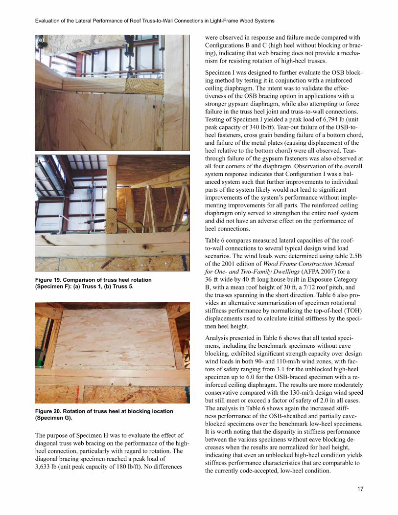
The purpose of Specimen H was to evaluate the effect of diagonal truss web bracing on the performance of the high-heel connection, particularly with regard to rotation. The diagonal bracing specimen reached a peak load of 3,633 lb (unit peak capacity of 180 lb/ft). No differences
were observed in response and failure mode compared with Configurations B and C (high heel without blocking or brac-ing), indicating that web bracing does not provide a mecha-nism for resisting rotation of high-heel trusses.
Specimen I was designed to further evaluate the OSB block-ing method by testing it in conjunction with a reinforced ceiling diaphragm. The intent was to validate the effec-tiveness of the OSB bracing option in applications with a stronger gypsum diaphragm, while also attempting to force failure in the truss heel joint and truss-to-wall connections. Testing of Specimen I yielded a peak load of 6,794 lb (unit peak capacity of 340 lb/ft). Tear-out failure of the OSB-to-heel fasteners, cross grain bending failure of a bottom chord, and failure of the metal plates (causing displacement of the heel relative to the bottom chord) were all observed. Tear-through failure of the gypsum fasteners was also observed at all four corners of the diaphragm. Observation of the overall system response indicates that Configuration I was a bal-anced system such that further improvements to individual parts of the system likely would not lead to significant improvements of the system’s performance without imple-menting improvements for all parts. The reinforced ceiling diaphragm only served to strengthen the entire roof system and did not have an adverse effect on the performance of heel connections.
Table 6 compares measured lateral capacities of the roof-to-wall connections to several typical design wind load scenarios. The wind loads were determined using table 2.5B of the 2001 edition of Wood Frame Construction Manual for One- and Two-Family Dwellings (AFPA 2007) for a 36-ft-wide by 40-ft-long house built in Exposure Category B, with a mean roof height of 30 ft, a 7/12 roof pitch, and the trusses spanning in the short direction. Table 6 also pro-vides an alternative summarization of specimen rotational stiffness performance by normalizing the top-of-heel (TOH) displacements used to calculate initial stiffness by the speci-men heel height.
Analysis presented in Table 6 shows that all tested speci-mens, including the benchmark specimens without eave blocking, exhibited significant strength capacity over design wind loads in both 90- and 110-mi/h wind zones, with fac-tors of safety ranging from 3.1 for the unblocked high-heel specimen up to 6.0 for the OSB-braced specimen with a re-inforced ceiling diaphragm. The results are more moderately conservative compared with the 130-mi/h design wind speed but still meet or exceed a factor of safety of 2.0 in all cases. The analysis in Table 6 shows again the increased stiff-ness performance of the OSB-sheathed and partially eave-blocked specimens over the benchmark low-heel specimens. It is worth noting that the disparity in stiffness performance between the various specimens without eave blocking de-creases when the results are normalized for heel height, indicating that even an unblocked high-heel condition yields stiffness performance characteristics that are comparable to the currently code-accepted, low-heel condition.
Figure 20. Rotation of truss heel at blocking location (Specimen G).
(a)
(b)
General Technical Report FPL–GTR–214
18
Summary and ConclusionsThis testing program was designed to benchmark the per-formance of traditional roof systems and incrementally improved roof-to-wall systems with the goal of developing connection solutions that are optimized for performance and constructability. The results of this study are expected to provide guidance toward determining appropriate trigger levels for continuous blocking between high-heel trusses and viable alternative blocking solutions to those currently required by code. The following is a summary of results of this testing program:
1. The benchmark code-allowed low-heel (9-1/4 in.) roof system with no blocking and hurricane truss clip connec-tions reached a peak unit capacity of 255 lb/ft.
2. The benchmark high-heel (15-1/4 in.) roof system with-out blocking achieved a peak unit capacity of 175 lb/ft. This is a 33% decrease in capacity compared with the low-heel configuration. The initial stiffness of the high-heel specimen was approximately half that of the low-heel specimen, indicating that heel height significantly affects truss rotation where no blocking is installed.
3. Comparison of performance results for high-heel trusses with two different roof slopes (7/12 and 3/12) indicates no measurable effect of roof slope on truss rotation at the heel.
4. The high-heel roof specimen with OSB sheathing used for heel bracing (Specimen D) exhibited a 26% increase in capacity over the benchmark high-heel test (220 lb/ft compared with 175 lb/ft) and only an 18% decrease in capacity compared with the benchmark low-heel test (220 lb/ft compared with 245 lb/ft). The addi-tion of the OSB sheathing also increased the specimen’s initial stiffness by 18% over the low-heel specimen (10,395 lb/in compared with 8,828 lb/in). This increase in stiffness, along with the reserve strength capacity over typical design wind loads, indicates that using OSB sheathing as bracing in the high-heel condition is compa-rable to the currently code-allowed, unblocked, low-heel truss condition.
5. Nailing the OSB sheathing to the supporting top plate (Specimen E) increased the capacity to 240 lb/ft. This is only 7% less than the low-heel configuration (Specimen B) and 7% higher than the intermittent blocking con-figuration (Specimen G). The attachment to the wall top plate also significantly increased the rotational stiffness of the heel joint exceeding that for the low-heel speci-men (32,224 lb/in compared with 8,828 lb/in).
6. High-heel systems with intermittent blocking amounts of 25% (Specimen F) and 50% (Specimen G) achieved peak unit capacities of 200 lb/ft and 225 lb/ft, respective-ly. Comparison of TOH displacements at both blocked and unblocked locations within Specimen F indicates
Table 6—Ratios of lateral roof connection capacity relative to typical design wind loadsa
Configuration
Factor of safety TOHdisplacementas percentage of heel heightc
90 mi/h,Exposure B
(39 lb/ft)
110 mi/h,Exposure B
(57 lb/ft)
130 mi/h, Exposure B(89 lb/ft)b
A Low-heel truss 6.6 4.5 2.9 1.0 B High-heel truss without blocking 4.5 3.1 2.0 1.2 C High-heel truss without blocking
with low (3/12) roof pitch 4.8 3.3 2.1 1.3
D High-heel truss braced with OSB sheathing
5.6 3.8 2.4 0.5
E High-heel truss braced with OSB sheathing extended over wall plate
6.1 4.2 2.7 0.2
F High-heel truss with blocking at intermittent locations
5.1 3.5 2.2 0.3
G High-heel truss with blocking at every other bay
5.8 4.0 2.5 0.3
H High-heel truss with braced webs 4.7 3.2 2.0 1.0 I High-heel truss braced with OSB
sheathing and a reinforced ceiling diaphragm
8.7 6.0 3.8 0.1
aTypical design wind loads calculated for a 36-ft-wide by 40-ft-long house built in Exposure Category B, with a mean roof height of 30 ft, a 7/12 roof pitch, and the trusses spanning in the short direction. bDesign wind loading at 130 mi/h and Exposure B is equivalent to the 110 mi/h and Exposure C design criteria that is the upper limit used in the 2012 IRC structural provisions. cTOH displacement measured at same load level as initial stiffness calculations (i.e., 760 lb).
Evaluation of the Lateral Performance of Roof Truss-to-Wall Connections in Light-Frame Wood Systems
19
that a single blocked bay provides rotational restraint to the entire specimen length (that is, the rotational restraint is not localized). Comparison of initial stiffness between Specimens F and G indicates that the addition of a sec-ond blocking panel provides only 12% greater rotational restraint to the specimen.
7. Comparison of Specimen E (OSB sheathing also nailed to the top plate) performance to that of the 50% intermit-tently blocked specimen (Specimen G) shows that Speci-men E exceeded Specimen G in both peak load capacity (240 lb/ft compared with 225 lb/ft) and initial stiffness (32,224 lb/in compared with 26,581 lb/in).
8. The addition of diagonal truss web bracing to a high-heel truss without any additional blocking provides no measurable improvement over the benchmark high-heel configuration in either peak unit capacity or rotational restraint.
Several conclusions can be drawn based on the results of this testing program. Comparing the performances of Speci-mens A and D shows that the OSB-sheathed high-heel truss detail yields comparable (and in terms of stiffness, superior) performance to that of the unblocked, low-heel truss con-figuration that is currently allowed by code (see Table 1 and Fig. 1). This performance, along with the reserve strength capacity over typical design wind loads, indicates that using OSB sheathing as bracing (without any additional blocking in the heel) can be considered an adequate bracing option in high-heel conditions where the intent is to provide structural performance comparable to that of an unblocked, low-heel truss condition.
Further comparison between Specimens E and F shows that extending the OSB sheathing down and including additional nailing to the top plate of the wall below provides superior strength and stiffness performance to that of the solid, in-termittent blocking that is currently required in high-wind regions and should be considered a viable truss heel bracing solution to said intermittent blocking.
ReferencesAFPA. 2007. Woodframe construction manual for one and two family dwellings (including 2007 errata/addendum). Leesburg, VA: American Wood Council.
ASCE. 2005. Minimum design loads for buildings and other structures. Reston, VA: American Society of Civil Engi-neers.
Gypsum Association. 2010. Application and finishing of gypsum panel products (GA-216-2010). Hyattsville, MD: Gypsum Association.
ICC. 2009. International residential code for one and two family dwellings. Country Club Hills, IL: International Code Council.
Kopp, G. 2010. Wind loading on low-rise buildings. In: Presentation at an expert meeting on IRC wind wall bracing: combined uplift and shear load path. Leesburg, VA.
Riley, M.; Sadek, F. 2003. Experimental testing of roof-to-wall connections in wood frame houses (NISTIR 6938). Gaithersburg, MD: National Institute of Standards and Tech-nology, Building and Fire Laboratory.
Scoville, E. 2005. Investigation of the response of low-rise wood-frame roof-wall systems under combined uplift and in-plane shear loads. Clemson, SC: Clemson University.
Simpson Strong-Tie. 2010. Personal communication, Randy Shackelford, Simpson Strong-Tie. Truss anchorage for mul-tiple loading, presentation of testing conducted at Clemson University.
General Technical Report FPL–GTR–214
20
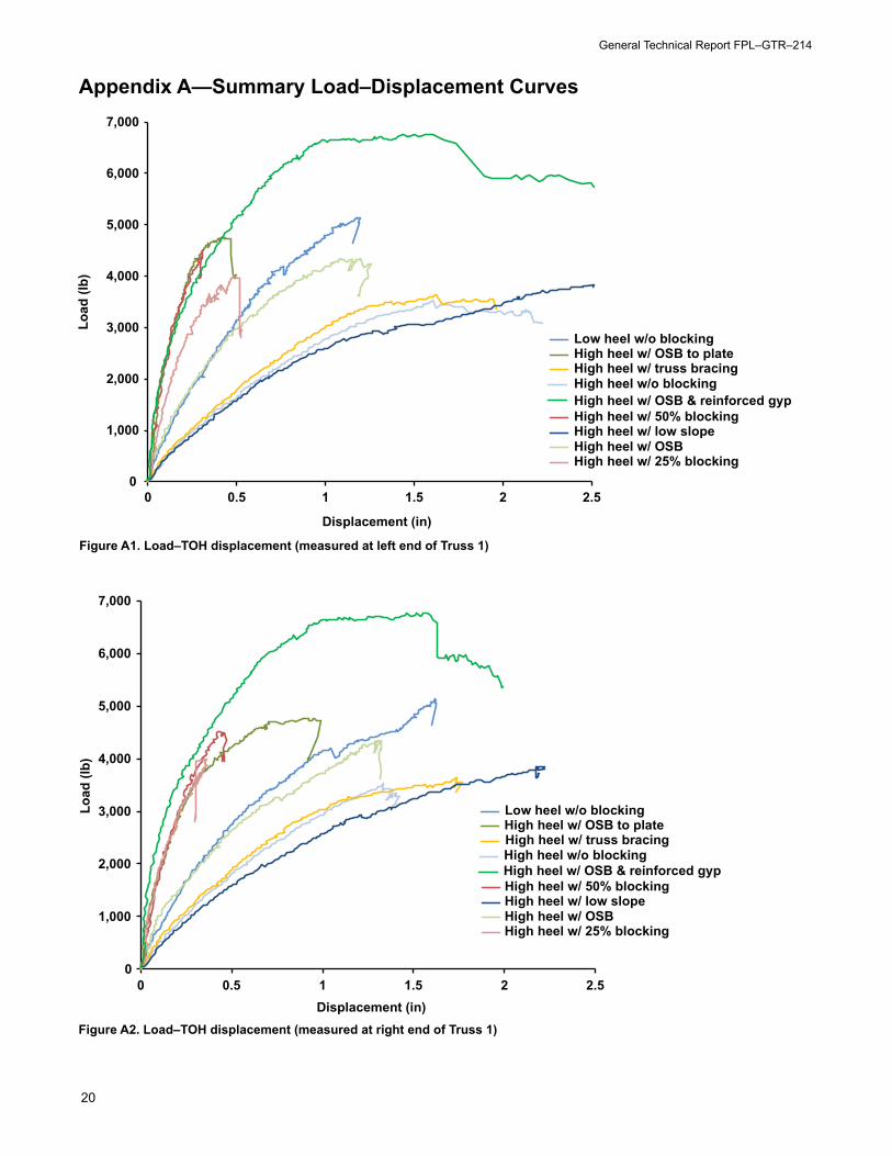
Appendix A—Summary Load–Displacement Curves
0
1,000
2,000
3,000
4,000
5,000
6,000
7,000
0 0.5 1 1.5 2 2.5
Load
(lb)
Displacement (in)
Low heel w/o blocking
High heel w/o blocking
High heel w/ OSB
High heel w/ OSB to plate
High heel w/ 50% blocking
High heel w/ 25% blocking
High heel w/ truss bracing
High heel w/ low slope
High heel w/ OSB & reinforced gyp
Figure A1. Load–TOH displacement (measured at left end of Truss 1)
0
1,000
2,000
3,000
4,000
5,000
6,000
7,000
0 0.5 1 1.5 2 2.5
Load
(lb)
Displacement (in)Figure A2. Load–TOH displacement (measured at right end of Truss 1)
Low heel w/o blocking
High heel w/o blocking
High heel w/ OSB
High heel w/ OSB to plate
High heel w/ 50% blocking
High heel w/ 25% blocking
High heel w/ truss bracing
High heel w/ low slope
High heel w/ OSB & reinforced gyp
Evaluation of the Lateral Performance of Roof Truss-to-Wall Connections in Light-Frame Wood Systems
21
Appendix B—Specimen Load–Displacement Curves
0
1,000
2,000
3,000
4,000
5,000
6,000
0 0.5 1 1.5 2 2.5 3 3.5 4
Load
(lb)
Displacement (in)
Top chordBottom chordTOH left T1TOH right T1
Figure B1. Specimen A
0
1,000
2,000
3,000
4,000
5,000
6,000
0 0.5 1 1.5 2 2.5 3 3.5 4
Load
(lb)
Displacement (in)
Top chordBottom chordTOH left T1TOH right T1
Figure B2. Specimen B
General Technical Report FPL–GTR–214
22
0
1,000
2,000
3,000
4,000
5,000
6,000
0 0.5 1 1.5 2 2.5 3 3.5 4
Load
(lb)
Displacement (in)
Top chordBottom chordTOH left T1TOH right T1
Figure B3. Specimen C
0
1,000
2,000
3,000
4,000
5,000
6,000
0 0.5 1 1.5 2 2.5 3 3.5 4
Load
(lb)
Displacement (in)
Top chordBottom chordTOH left T1TOH right T1
Figure B4. Specimen D
Evaluation of the Lateral Performance of Roof Truss-to-Wall Connections in Light-Frame Wood Systems
23
0
1,000
2,000
3,000
4,000
5,000
6,000
0 0.5 1 1.5 2 2.5 3 3.5 4
Load
(lb)
Displacement (in)
Top chordBottom chordTOH left T1TOH right T1
Figure B5. Specimen E
0
1,000
2,000
3,000
4,000
5,000
6,000
0 0.5 1 1.5 2 2.5 3 3.5 4
Load
(lb)
Displacement (in)
Top chordBottom chordTOH left T1TOH left T4TOH right T1TOH right T4
Figure B6. Specimen F
General Technical Report FPL–GTR–214
24
0
1,000
2,000
3,000
4,000
5,000
6,000
0 0.5 1 1.5 2 2.5 3 3.5 4
Load
(lb)
Displacement (in)
Top chordBottom chordTOH left T1TOH left T4TOH right T1TOH right T4
Figure B7. Specimen G
0
1,000
2,000
3,000
4,000
5,000
6,000
0 0.5 1 1.5 2 2.5 3 3.5 4
Load
(lb)
Displacement (in)
Top chordBottom chordTOH left T1TOH right T1
Figure B8. Specimen H
Evaluation of the Lateral Performance of Roof Truss-to-Wall Connections in Light-Frame Wood Systems


![Tendars tent catalog€¦ · [GA TENT 2014 CATALOG] eave corner eave corner ridge baseplate at the bracang connection baseplate (field) Item Clear-span Width Eave height Ridge height](https://static.documents.pub/doc/80x56/5edd30dcad6a402d666830e8/tendars-tent-catalog-ga-tent-2014-catalog-eave-corner-eave-corner-ridge-baseplate.jpg)


