7.1 What can I do if the fan blades touch the venturi? 7.2 What can I do if the fan does not come on?
7.3 What can I do if the pads are not getting wet?
7.4 What can I do if there is low airflow in the cool mode?
Aqua Breeze Installation Instructions 02/010 Page 3
1. Introduction
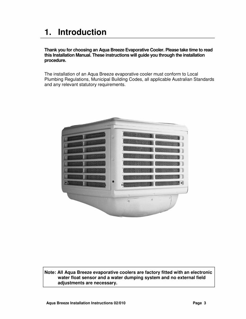
Thank you for choosing an Aqua Breeze Evaporative Cooler. Please take time to read this Installation Manual. These instructions will guide you through the installation procedure.
The installation of an Aqua Breeze evaporative cooler must conform to Local Plumbing Regulations, Municipal Building Codes, all applicable Australian Standards and any relevant statutory requirements.
Note: All Aqua Breeze evaporative coolers are factory fitted with an electronic water float sensor and a water dumping system and no external field adjustments are necessary.
Aqua Breeze Installation Instructions 02/010 Page 4
2. Preparing for Installation
2.1 Packaging
The Aqua Breeze evaporative cooler comprises of three packages
1. Evaporative Cooler Unit
2. Weatherseal and assorted parts
3. Wall controller
Upon delivery please check all packages for any damage or missing parts and report any irregularities to your Aqua Breeze dealer.
Note: Open the weather seal package and check its contents with list below and then prepare the sub-assembly as shown on page 4.
2.1.1 Weather seal package contents
Qty
• Weather seal assembly 1
• Corner mounting brackets 4
• Cable ties 4
• 44 mm plastic grommets 2
• Plastic screw rivets (for Model A143&A162 only) 6
• Self drill screws #8 x ½” 16
• Self tap screws #8 x ½” 8
• Warranty card 1
• 40mm PVC pipe 1
• IEC Power cord 1
• RJ45 loom (20 metre) 1
• Flexible hose (3/4”BSP to ½” olive) 1
• Operating Instructions 1
• Installation Instructions 1
Aqua Breeze Installation Instructions 02/010 Page 5
Preparing for Installation (cont)
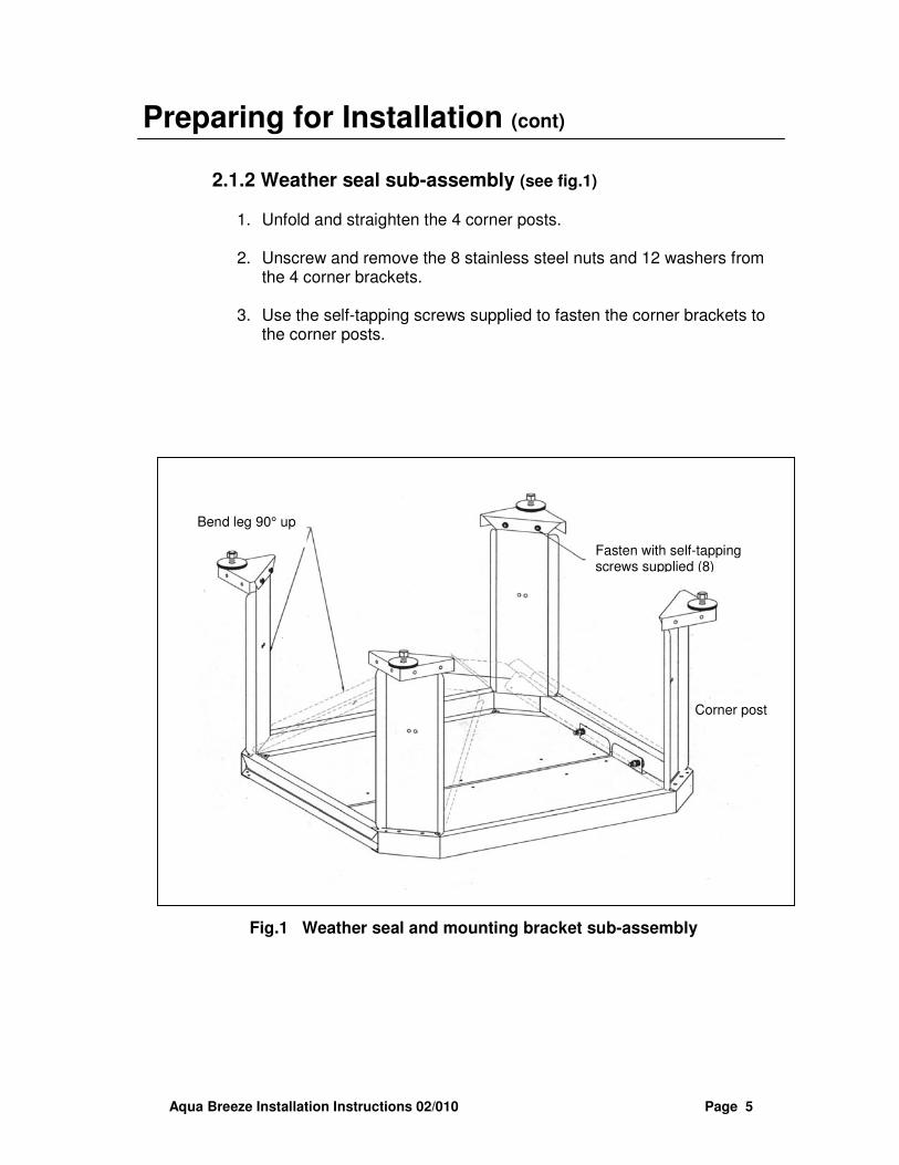
2.1.2 Weather seal sub-assembly (see fig.1)
1. Unfold and straighten the 4 corner posts. 2. Unscrew and remove the 8 stainless steel nuts and 12 washers from
the 4 corner brackets. 3. Use the self-tapping screws supplied to fasten the corner brackets to
the corner posts.
Fig.1 Weather seal and mounting bracket sub-assembly
Bend leg 90° up
Fasten with self-tapping screws supplied (8)
Corner post
Aqua Breeze Installation Instructions 02/010 Page 6
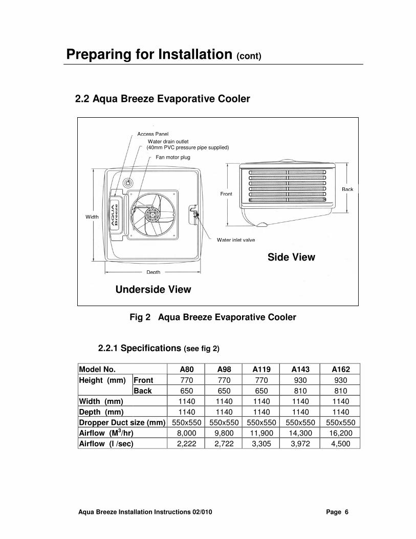
Water drain outlet (40mm PVC pressure pipe supplied)
Fan motor plug
Water inlet valve
Front Back
Underside View
Width
Depth
Side View
Aqua Breeze Installation Instructions 02/010 Page 7
Note: The unit selection and design of system must meet Aqua Breeze requirements. Any costs due to incorrect unit selection and ductwork sizing will be the responsibility of the dealer.
Preparing for Installation (cont)
2.3 Guidelines for unit location on roof
The Aqua Breeze evaporative cooler is designed for external installation and requires 100% outside air. Unit location must meet the following requirements:
• Unit must be easily accessible for servicing.
• Unit must be mounted as low as possible to the roof and to the rear of the house.
• Unit must be placed well away from toilet pipe, flue terminals and sources of smoke, dust and objectionable fumes so that only clean, fresh outside air will be drawn into the unit.
• Unit must be placed on the side of the house that receives the prevailing hot winds. This avoids too much heat leaking in from the open windows and doors that exhaust the air.
• Unit must be placed on building structures capable of supporting its weight.
• Installation must comply to meet all Local Council and EPA requirements.
Note: It is the installer’s responsibility to ensure the location of unit meets our installation requirements. Aqua Breeze reserves the right to refuse service unless safety and accessibility to the unit can be guaranteed.
Aqua Breeze Installation Instructions 02/010 Page 8
3. Installation
3.1 Installing the Dropper Box
All Aqua Breeze evaporative coolers are designed to be fully supported by a dropper box. Correct installation of the dropper box is vital to the installation and operation of the unit
All Aqua Breeze evaporative coolers are specifically designed for use with a 550mm x 550mm dropper.
3.1.1 Guidelines for Installation of Dropper Box
The following requirements for dropper box installation must be met for a good unit installation:
• The dropper box must be square and level after installation.
• The bottom of dropper box should not touch ceiling joists or other structural members. This will prevent noise and vibration transmission through the building.
• The dropper box must be mounted firmly and securely to the roof trusses and be vibration free.
• The weather seal is designed to fit an uninsulated dropper box and care should be taken to make sure the dropper box insulation (when used) does not interfere with the weather seal operation.
• The dropper box, water supply pipe and the drain must be fully flashed and sealed to prevent water entering into the building.
• It is recommended that a splitter pyramid be fitted on the base of the dropper box to improve airflow and reduce noise.
Aqua Breeze Installation Instructions 02/010 Page 9
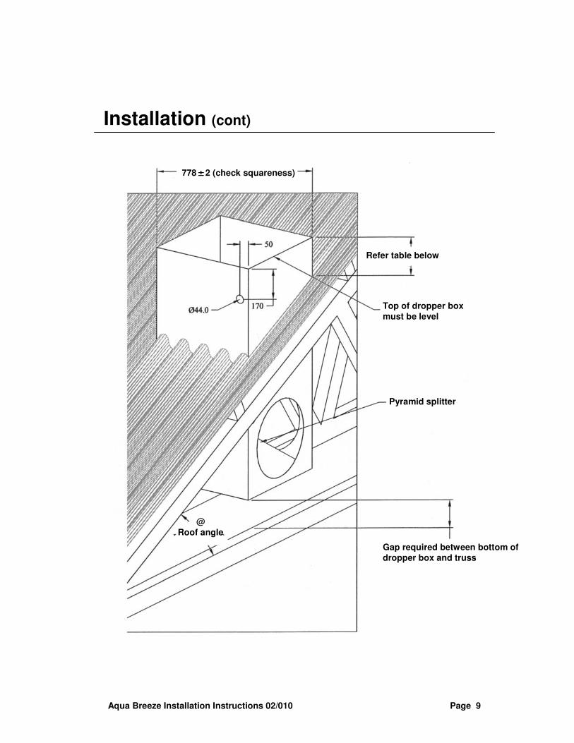
Installation (cont)
778±±±±2 (check squareness)
Refer table below
Top of dropper box must be level
Pyramid splitter
Gap required between bottom of dropper box and truss
@ Roof angle
Aqua Breeze Installation Instructions 02/010 Page 10
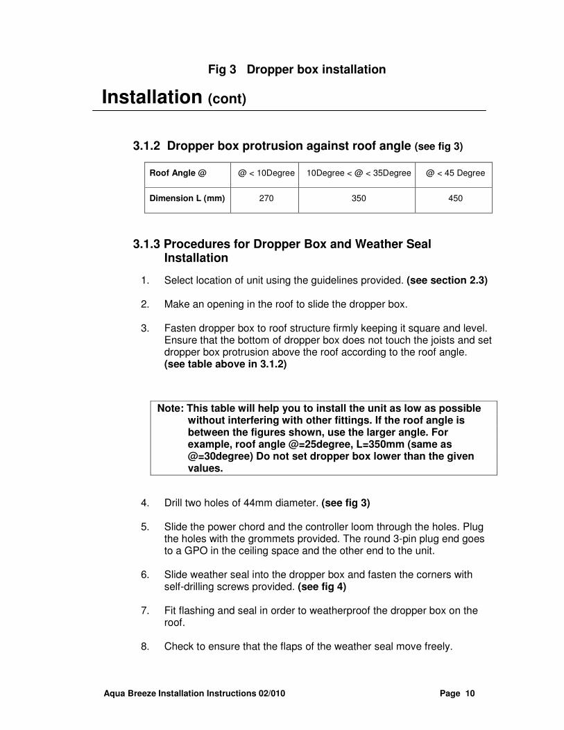
Fig 3 Dropper box installation
Installation (cont)
3.1.2 Dropper box protrusion against roof angle (see fig 3)
3.1.3 Procedures for Dropper Box and Weather Seal Installation
1. Select location of unit using the guidelines provided. (see section 2.3) 2. Make an opening in the roof to slide the dropper box.
3. Fasten dropper box to roof structure firmly keeping it square and level.
Ensure that the bottom of dropper box does not touch the joists and set dropper box protrusion above the roof according to the roof angle. (see table above in 3.1.2)
Note: This table will help you to install the unit as low as possible without interfering with other fittings. If the roof angle is between the figures shown, use the larger angle. For example, roof angle @=25degree, L=350mm (same as @=30degree) Do not set dropper box lower than the given values.
4. Drill two holes of 44mm diameter. (see fig 3)
5. Slide the power chord and the controller loom through the holes. Plug
the holes with the grommets provided. The round 3-pin plug end goes to a GPO in the ceiling space and the other end to the unit.
6. Slide weather seal into the dropper box and fasten the corners with
self-drilling screws provided. (see fig 4) 7. Fit flashing and seal in order to weatherproof the dropper box on the
roof.
8. Check to ensure that the flaps of the weather seal move freely.
Aqua Breeze Installation Instructions 02/010 Page 11
Installation (cont)
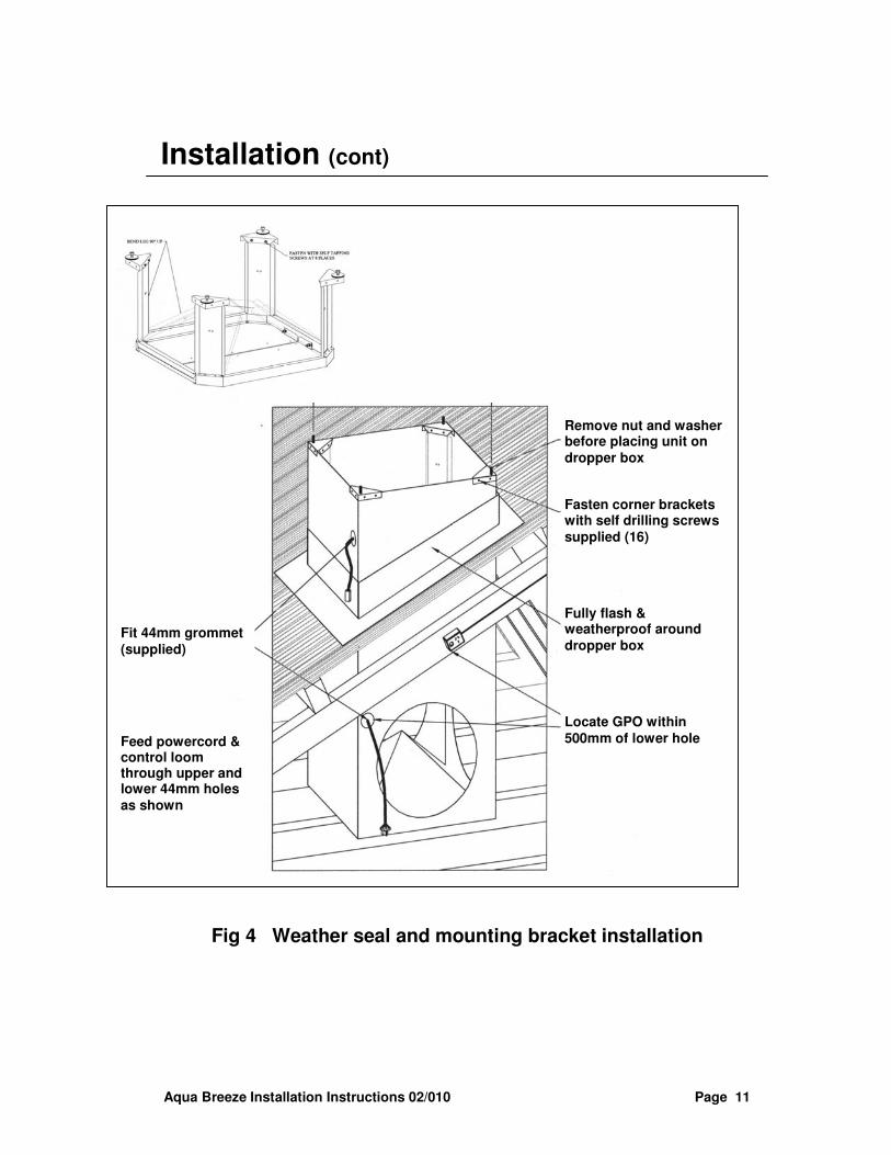
Fig 4 Weather seal and mounting bracket installation
Remove nut and washer before placing unit on dropper box
Fasten corner brackets with self drilling screws supplied (16)
Fully flash & weatherproof around dropper box
Locate GPO within 500mm of lower hole
Fit 44mm grommet (supplied)
Feed powercord & control loom through upper and lower 44mm holes as shown
Aqua Breeze Installation Instructions 02/010 Page 12
Installation (cont)
3.2 Installing the Evaporative Cooler
Note: Aqua Breeze evaporative coolers are designed for easy installation. The following procedures will help to reduce installation time and ensure trouble free installation.
3.2.1 Procedure for Unit installation
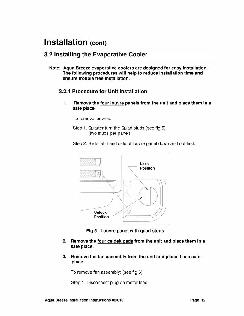
1. Remove the four louvre panels from the unit and place them in a
safe place.
To remove louvres:
Step 1. Quarter turn the Quad studs (see fig 5) (two studs per panel)
Step 2. Slide left hand side of louvre panel down and out first.
Fig 5 Louvre panel with quad studs
2. Remove the four celdek pads from the unit and place them in a
safe place.
3. Remove the fan assembly from the unit and place it in a safe place.
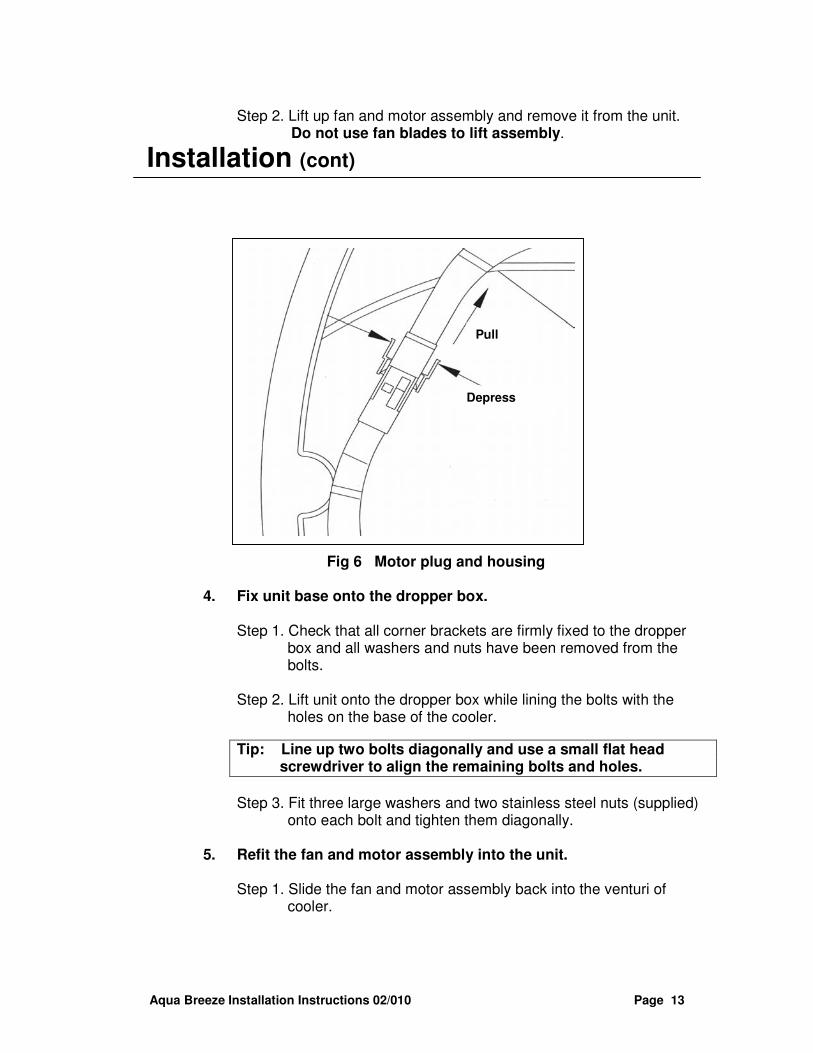
To remove fan assembly: (see fig 6)
Step 1. Disconnect plug on motor lead.
Lock Position
Unlock Position
Aqua Breeze Installation Instructions 02/010 Page 13
Step 2. Lift up fan and motor assembly and remove it from the unit. Do not use fan blades to lift assembly.
Installation (cont)
Fig 6 Motor plug and housing
4. Fix unit base onto the dropper box.
Step 1. Check that all corner brackets are firmly fixed to the dropper
box and all washers and nuts have been removed from the bolts.
Step 2. Lift unit onto the dropper box while lining the bolts with the
holes on the base of the cooler.
Tip: Line up two bolts diagonally and use a small flat head screwdriver to align the remaining bolts and holes.
Step 3. Fit three large washers and two stainless steel nuts (supplied) onto each bolt and tighten them diagonally.
5. Refit the fan and motor assembly into the unit.
Step 1. Slide the fan and motor assembly back into the venturi of
cooler.
Depress
Depress
Depress
Pull
Aqua Breeze Installation Instructions 02/010 Page 14
Note: The fan bracket has two notches and must fit into the two lugs in the venturi.
Installation (cont)
5. Refit the fan and motor assembly into the unit (cont).
Step 2. Reconnect the motor plug. Ensure plug is locked into position. (see fig 6)
Note: The motor plug is polarised and it will only fit in one way. Step 3. Rotate fan by hand. Blades must not touch venturi. If the
blades rub against the venturi then loosen the four mounting nuts and reposition the unit to make it square and then re-tighten mounting nuts.
Step 4. Set water flow regulator, located on the inside of the front right
hand side corner pillar to the 11 o’clock position. This regulator is inline with the hose leading to the water distributor and is located behind the aluminum corner pillar.
Step 5. Refit the four pads. Ensure that the large flange is at the top.
6. Plug power cord and control loom in control panel.
Step 1. Remove access panel by unscrewing the three self-tappers.
Step 2. Plug power cord and control loom into labelled sockets.
Step 3. Re-fit access panel. (Access panel can be left off for testing
later.)
WARNING: Power must not be turned on, even if it is available.
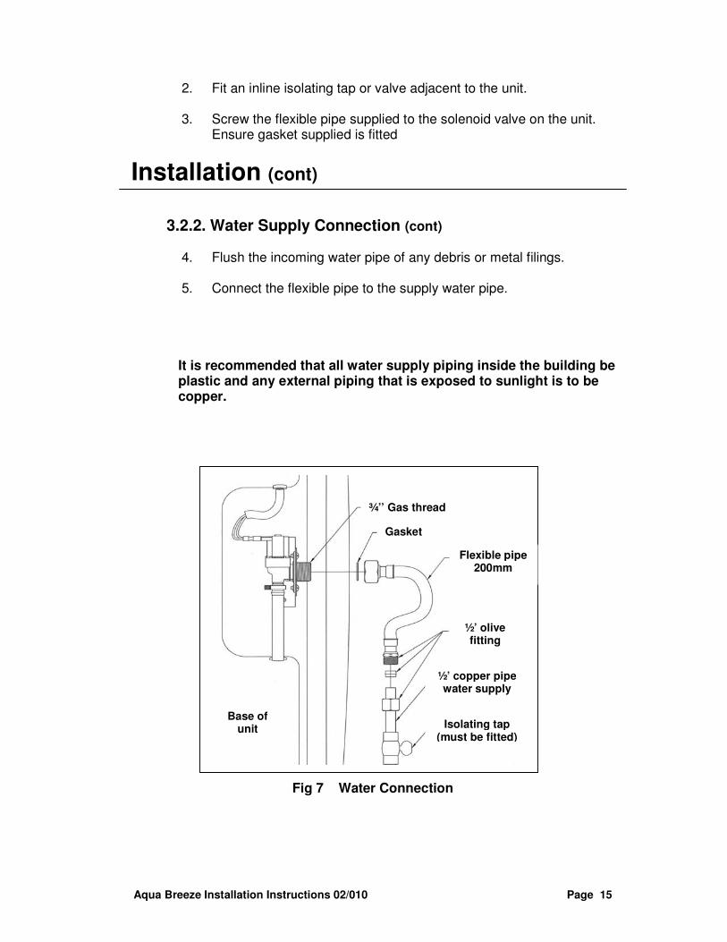
3.2.2. Water Supply Connection. (see fig 7)
Note: All water piping work and connection to the unit must be
installed by a licensed plumber and must conform to all local regulations. Follow the steps given below.
1. Run ½” water supply pipe to the unit.
Aqua Breeze Installation Instructions 02/010 Page 15
2. Fit an inline isolating tap or valve adjacent to the unit. 3. Screw the flexible pipe supplied to the solenoid valve on the unit.
Ensure gasket supplied is fitted
Installation (cont)
3.2.2. Water Supply Connection (cont)
4. Flush the incoming water pipe of any debris or metal filings.
5. Connect the flexible pipe to the supply water pipe.
It is recommended that all water supply piping inside the building be plastic and any external piping that is exposed to sunlight is to be copper.
Fig 7 Water Connection
¾’’ Gas thread
Gasket
Flexible pipe 200mm
½’ olive fitting
½’ copper pipe water supply
Isolating tap (must be fitted)
Base of unit
Aqua Breeze Installation Instructions 02/010 Page 16
Note: Ensure all pipe work is secured and weatherproofed at roof penetration. All pipe work has to be designed to minimize water hammer noise.
Installation (cont)
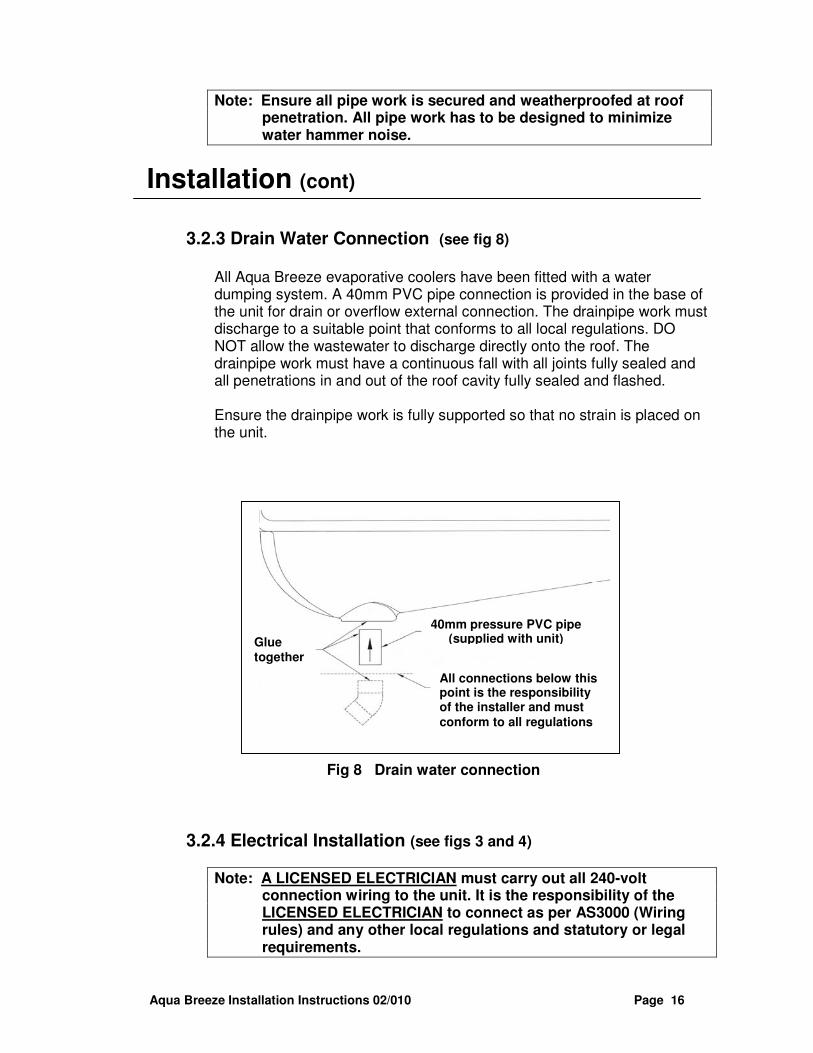
3.2.3 Drain Water Connection (see fig 8)
All Aqua Breeze evaporative coolers have been fitted with a water dumping system. A 40mm PVC pipe connection is provided in the base of the unit for drain or overflow external connection. The drainpipe work must discharge to a suitable point that conforms to all local regulations. DO NOT allow the wastewater to discharge directly onto the roof. The drainpipe work must have a continuous fall with all joints fully sealed and all penetrations in and out of the roof cavity fully sealed and flashed.
Ensure the drainpipe work is fully supported so that no strain is placed on the unit.
Fig 8 Drain water connection
3.2.4 Electrical Installation (see figs 3 and 4)
Note: A LICENSED ELECTRICIAN must carry out all 240-volt connection wiring to the unit. It is the responsibility of the LICENSED ELECTRICIAN to connect as per AS3000 (Wiring rules) and any other local regulations and statutory or legal requirements.
40mm pressure PVC pipe (supplied with unit)
All connections below this point is the responsibility of the installer and must conform to all regulations
Glue together
Aqua Breeze Installation Instructions 02/010 Page 17
A 10A GPO (general purpose outlet) is required within 500mm of the bottom 44mm hole made in the dropper box (see fig 4). Plug in the 3 pin plug to the GPO. Do not turn on the power.
Installation (cont)
3.2.5 Wall Control Connection.
1. Select a suitable location inside the house to mount the controller. Avoid any direct sunlight or heat sources.
2. Mark the mounting holes and outline the controller socket on the wall. 3. Drill the mounting holes and make provision in the wall for the
controller socket. 4. Pull plug and loom through the hole in the wall. 5. Fit plastic wall plugs (supplied) into the holes in the wall. 6. Blow away any dust that might have entered into the connections then
plug loom into the controller socket.
7. Screw the controller onto the wall and plug controller holes with the plastic caps supplied.
TIP: When pulling through loom, place plastic over connector to avoid damage or dust.
3.2.6 Wiring Module
Aqua Breeze Installation Instructions 02/010 Page 18
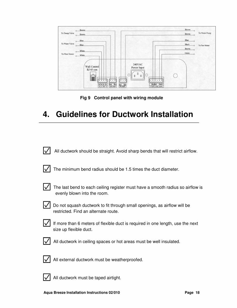
Fig 9 Control panel with wiring module
4. Guidelines for Ductwork Installation
���� All ductwork should be straight. Avoid sharp bends that will restrict airflow.
���� The minimum bend radius should be 1.5 times the duct diameter.
���� The last bend to each ceiling register must have a smooth radius so airflow is
evenly blown into the room.
���� Do not squash ductwork to fit through small openings, as airflow will be
restricted. Find an alternate route.
���� If more than 6 meters of flexible duct is required in one length, use the next
size up flexible duct.
���� All ductwork in ceiling spaces or hot areas must be well insulated.
���� All external ductwork must be weatherproofed.
���� All ductwork must be taped airtight.
Aqua Breeze Installation Instructions 02/010 Page 19
���� Always install damper blades in the system.
���� Adjust dampers as required to ensure even air distribution.
5. Commissioning
Note: To cut down commissioning time the installer should carry a 1-meter long WJ45 loom and a spare controller. By plugging it into the unit, the installer can operate the cooler while on the roof. Please contact the sales department for more details.
• Turn on power from GPO to the unit.
• Turn on supply water to the unit.
1. Fan Operation
• Press FAN ONLY button and check that the fan blades are not touching the venturi. If fan blades are touching the venturi, please refer to the Trouble Shooting section at the back of this manual.
• Using the STEP button check that the fan speed varies up and down.
• Check that the weather seal opens and closes on startup and shutdown of the fan.
• Check that the air is being distributed and balanced through the ductwork.
• Press FAN ONLY button again to switch unit off. 2. Cool Operation
• Press ON/OFF COOL button.
• After a short delay the water solenoid valve will open and allow water to fill the internal reservoir.
• The pump will start and water will be distributed to wet the pads.
• The fan will start operating after the pads have been wet. NOTE: The controller is thermostatically controlled and the fan may run at minimum speed if the room temperature is 21� or below. The automatic function can be over-ridden by pressing the FAN ONLY button. This allows the fan in manual mode.
Aqua Breeze Installation Instructions 02/010 Page 20
3. Water Flow Regulator
• Check that while the unit is operating water is not dripping from the lid.
• If water is dripping from the lid adjust the water flow regulator located inside the front right hand pillar.
4. Water Bleeder
• No need for any adjustments as it is factory set.
5. Water Level Adjustment
• No need for any adjustments as this function is controlled by the microprocessor.
6. Check list
6.1 Final rooftop checklist.
���� All wiring plugs and access cover is in place.
���� All louvres are in place.
���� Dropper box and water supply pipe have both been flashed and sealed
to prevent water entry into the building.
���� Water drainpipe work is completed and sealed.
���� All rubbish has been removed from the roof.
6.2 Ductwork and general checklist.
���� All ductwork is completed according to design and correctly supported
and airtight, with no bends less than 1.5 X the duct diameter.
���� Air distribution checked, dampers are adjusted and all outlets correctly
adjusted and wiped clean.
���� All roof penetrations are fully sealed and watertight.
���� Manhole cover replaced.
���� All rubbish has been removed from inside and on the roof.
6.3 Customer Hand Over checklist
Aqua Breeze Installation Instructions 02/010 Page 21
���� The customer is shown the operation of the controller with emphasis
on its operation in the automatic mode (Airflow might not be felt at low room temperature at 21deg)
���� The need to open windows and doors for the correct operation of the
cooler.
���� Maintenance requirements that the unit be serviced once every two to
three years depending on the ambient environment.
���� The customer is handed over the Operating Manual.
7. Installation Troubleshooting
7.1 What if the fan blades touch the venturi?
• To maximize airflow and minimize noise levels, Aqua Breeze evaporative coolers have a very tight tolerance between fan blades and the venturi. The motor bracket and venturi is designed to maintain fan rotation without interference. There are two possible reasons for fan blade interference.
1. The notches on the motor bracket are not seated in the lugs on
the venturi. To rectify, align motor bracket with lugs.
2. The dropper box is not the correct size or is not square. This forces the venturi out of shape. (refer section on dropper box installation). To rectify, remove mounting nuts and washers again and enlarge mounting holes on base. Realign and refit washers and nuts.
7.2 What if the fan does not come on?
For easy installation and service all fan motors are fitted with polarized plugs, which can only be plugged in one way. Remove motor plug, check its polarity with the loom housing and re-fit plug making sure it is locked in.
7.3 What if the pads are not getting wet?
• Check that the water supply tap is turned on.
Aqua Breeze Installation Instructions 02/010 Page 22
• Check that the pads are fitted in correctly.
7.4 What if there is low airflow in the cool mode?
• When the ON/OFF COOL button is pressed the cooler automatically
selects the fan speed. It might appear that the fan is not operating or the airflow is too low for your comfort. You can over-ride the automatic function by pressing the FAN ONLY button and use the STEP button and set the fan speed to the desired level.