ABSTRACT Superconducting transformers using high current density High Tempe- rature Superconductor (HTS) wire cooled with liquid nitrogen can be lighter and more efficient than con- ventional power transformers. This paper describes the 1 MVA 11/0.415 kV HTS transformer developed by a New Zealand - Australian team, featuring HTS Roebel cable in the 1.4 kA-rated low voltage winding. Comparison of HTS and conventional transformer designs at 40 MVA rating shows low- er lifetime cost of losses makes HTS base-load transformers cost-com- petitive in higher energy cost mar- kets. Power density - more MVA in a restricted footprint - could be a deci- sive advantage in mobile applications. KEYWORDS superconductor, Roebel cable, cryo- genic TECHNOLOGY 90 TRANSFORMERS MAGAZINE | Volume 3, Issue 3
Transcript
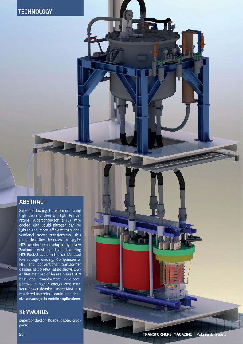
ABSTRACT Superconducting transformers using high current density High Tempe-rature Superconductor (HTS) wire cooled with liquid nitrogen can be lighter and more efficient than con-ventional powe r transformers. This paper describes the 1 MVA 11/0.415 kV HTS transformer developed by a New Z ealand - Australian team, featuring HTS Roebel cable in the 1.4 kA-rated low voltage winding. Comparison of HTS and conventional transformer designs at 40 MVA rating shows low-er lifetime cost of losses makes HTS base-load transformers cost-com-petitive in higher energy cost mar-kets. P ower density - more MVA in a restrict ed footprint - could be a deci-sive advantage in mobile applications.
KEYWORDSsuperconductor, Roebel cable, cryo-genic
EVENTSEVENTSTECHNOLOGY
90 TRANSFORMERS MAGAZINE | Volume 3, Issue 3
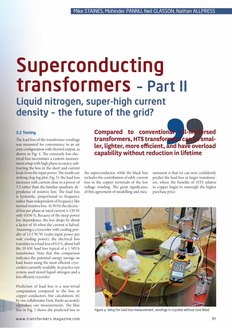
Figure 4. Setup for load loss measurement, windings in cryostat without core fitted
3.2 Testing
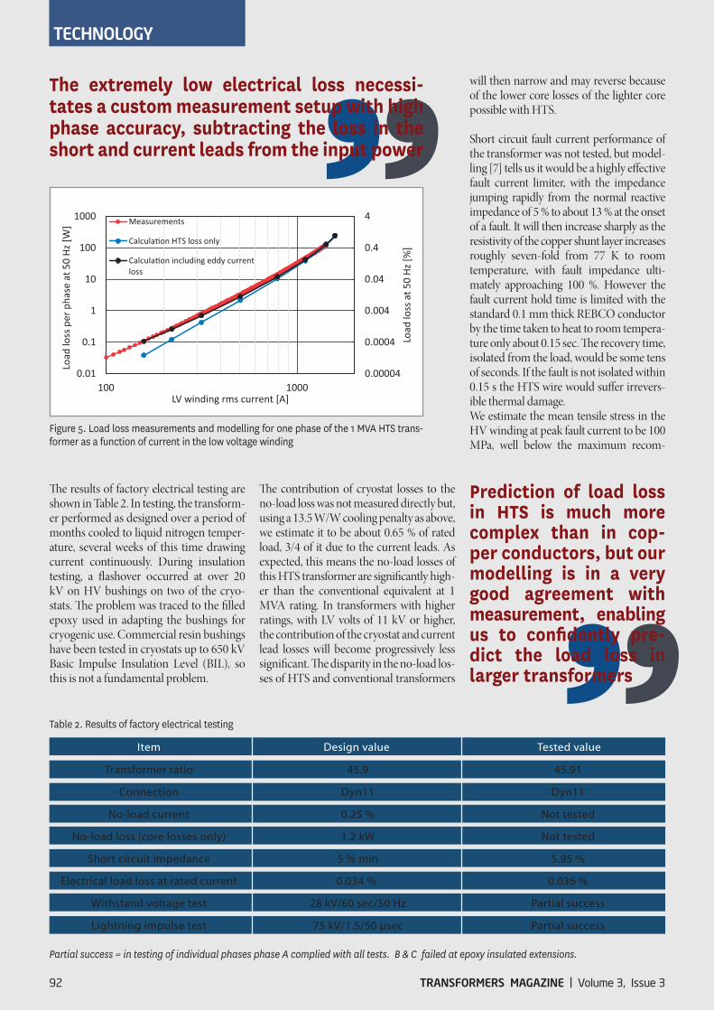
The load loss of the transformer windings was measured for convenience in an air core configuration with shorted output, as shown in Fig. 4. The extremely low elec-trical loss necessitates a custom measure-ment setup with high phase accuracy, sub-tracting the loss in the short and current leads from the input power. The results are striking (log-log plot, Fig. 5): the load loss increases with current close to a power of 3.5 rather than the familiar quadratic de-pendence of resistive loss. The load loss is hysteretic, proportional to frequency rather than independent of frequency like normal resistive loss. At 50 Hz the electric-al loss per phase at rated current is 120 W, only 0.036 %. Because of the steep power law dependence, the loss drops by about a factor of 10 when the current is halved. Assuming a cryocooler with cooling pen-alty of 13.5 W/W (watts input power per watt cooling power), the electrical loss translates to a load loss of 0.4 %, about half the 10 kW load loss typical of a 1 MVA transformer. Note that this comparison indicates the potential energy savings on load losses using the most efficient cryo-coolers currently available. In practice our system used stored liquid nitrogen and a less efficient crycooler.
Prediction of load loss is a non-trivial computation compared to the loss in c opper conductors, but calculations [6] by our collaborator Enric Pardo accurately reproduce our measurements. The blue line in Fig. 5 shows the predicted loss in
the superconductor, while the black line includes the contribution of eddy current loss in the copper terminals of the low voltage winding. The great significance of this agreement of modelling and mea-
surement is that we can now confidently predict the load loss in larger transform-ers, where the benefits of HTS relative to copper begin to outweigh the higher purchase price.
Compared to conventional oil-immersed transformers, HTS transformers can be smal-ler, lighter, more efficient, and have overload capability without reduction in lifetime
Superconducting transformers – Part IILiquid nitrogen, super-high current density – the future of the grid?
www.transformers-magaz ine .com 91
Mike STAINES, Mohinder PANNU, Neil GLASSON, Nathan ALLPRESS
will then narrow and may reverse because of the lower core losses of the lighter core possible with HTS.
Short circuit fault current performance of the transformer was not tested, but model-ling [7] tells us it would be a highly effective fault current limiter, with the impedance jumping rapidly from the normal reactive impedance of 5 % to about 13 % at the onset of a fault. It will then increase sharply as the resistivity of the copper shunt layer in creases roughly seven-fold from 77 K to room temperature, with fault impedance ulti-mately approaching 100 %. However the fault current hold time is limited with the standard 0.1 mm thick REBCO conductor by the time taken to heat to room tempera-ture only about 0.15 sec. The recovery time, isolated from the load, would be some tens of seconds. If the fault is not isolated within 0.15 s the HTS wire would suffer irrevers-ible thermal damage.We estimate the mean tensile stress in the HV winding at peak fault current to be 100 MPa, well below the maximum recom-
The results of factory electrical testing are shown in Table 2. In testing, the transform-er performed as designed over a period of months cooled to liquid nitrogen temper-ature, several weeks of this time drawing current continuously. During insulation testing, a flashover occurred at over 20 kV on HV bushings on two of the cryo-stats. The problem was traced to the filled epoxy used in adapting the bushings for cryo genic use. Commercial resin bushings have been tested in cryostats up to 650 kV Basic Impulse Insulation Level (BIL), so this is not a fundamental problem.
The contribution of cryostat losses to the no-load loss was not measured directly but, using a 13.5 W/W cooling penalty as above, we estimate it to be about 0.65 % of rated load, 3/4 of it due to the current leads. As expected, this means the no-load losses of this HTS transformer are significantly high-er than the conventional equivalent at 1 MVA rating. In transformers with higher ratings, with LV volts of 11 kV or higher, the contribution of the cryostat and current lead losses will become progressively less sig nificant. The disparity in the no-load los-ses of HTS and conventional transformers
Table 2. Results of factory electrical testing
Partial success = in testing of individual phases phase A complied with all tests. B & C failed at epoxy insulated extensions.
The extremely low electrical loss necessi-tates a custom measurement setup with high phase accuracy, subtracting the loss in the short and current leads from the input power
Prediction of load loss in HTS is much more complex than in cop-per conductors, but our modelling is in a very good agreement with measurement, enabling us to confidently pre-dict the load loss in l arger transformers
Figure 5. Load loss measurements and modelling for one phase of the 1 MVA HTS trans-former as a function of current in the low voltage winding
would be 0.09 %, compared with typical values of around 0.3 % for conventional transformers of this rating. How much is such low loss worth? This depends on the value ascribed to losses - the loss evalu-ation factor [10], dollars per kW of lifetime losses. These numbers can vary substan tially in different markets [11] with no-load loss evaluation factors in some European markets twice those in the United States, for example. The loss evaluation factor for load loss, labelled B, is typically 30 % of the no-load loss factor A. Fig. 6 compares TCO as function of no-load loss evalu ation factor for a 40 MVA 110/11 kV transform-er design. The copper designs have been optimised for minimum TCO as the loss evaluation factors vary. Fire protection costs estimated at 15 % of purchase price have been included in the copper trans-former purchase and installation costs. Apart from cryocooler maintenance costs, maintenance costs have been assumed the same for HTS and conventional transform-
ers and omitted. We will need to accu-mulate more experience with closed-cycle transformer cooling systems before we can quantify any cost advantage to HTS from eliminating oil maintenance costs.
For transformers operating at 100 % load factor (solid lines), e.g. base-load gener-ator step-up transformers, the savings in lifetime cost of losses compared to a conventional transformer are enough to make HTS competitive in markets with loss evaluation factors greater than about 7,000 US$/kW despite the higher initial purchase price.
In the case of transformers operating at lower load factor, with the load loss evalu-ation factor assumed to be 30 % of the no-load loss evaluation factor (dashed lines), the HTS transformer will have higher cost of ownership even at very high loss evalu-ation factors.
mended stress for the wire of 700 MPa. The LV winding is not designed to be self-sup-porting under fault current stresses, and is supported by a 10 mm thick GRE former, with the cable restrained within a 2 mm deep helical recess machined in the former.
4. Economics
It is unlikely that HTS transformers with ratings of a few MVA or less will ever be commercially competitive with conven-tional transformers. But how do the rela-tive costs stack up at higher ratings? In a recent study, making use of the validated loss modelling method [5], we estimated the Total Cost of Ownership (TCO) of a 40 MVA 110/11 kV HTS transformer design compared to a conventional trans-former [8]. The purchase price of the HTS transformer is estimated to be around 65 % high er than the conventional design. M ajor components of the cost are the su-perconducting wire and the cryosystem, each roughly a third of the total. A number of considerations influenced the choice of a 40 MVA rating: it represents a significant step up from previous HTS transformers into the range where commercial compet-itiveness might be expected, not too l arge for modelling validity or a design and build project, and a sizeable market sector. We make the assumption that 110 kV rated high voltage windings are achievable with HTS wire. Potential problems with partial discharge at the edges of the thin HTS tape can be circumvented by laminating with metal stabiliser with radi used edges. Wind-ings of 138 kV insulation class have been successfully tested [9].
40 MVA is not an upper limit for HTS transformers. The present limit for con-ductor critical current is around 90 A/mm at 77 K, 180 A/mm at 65 K. Using wide HTS conductor generally results in higher losses. Fully transposed high current wind-ings can be realised with Roebel cable, with the limit perhaps around 300 MVA for a 220/22 kV transformer, depending on the strand count in the cable, before resorting to connecting strands in parallel without transposition. The majority of demonst-ration HTS transformers have in fact used parallel conductors with varying degrees of transposition to achieve high current.
4.1 Reduced cost of losses
The loss modelling shows that at 40 MVA the load losses (including cooling penalty)
The loss modelling shows that at 40 MVA the load losses (including cooling penalty) would be 0.09 % compared with typical values of around 0.3 % for conventional transformers of this rating
It is unlikely that HTS transformers with rat-ings of a few MVA or less will ever be com-mercially competitive with conventional transformers
Figure 6. Comparison of the total cost of ownership of HTS and optimised copper 40 MVA transformers as a function of no-load loss evaluation factor A
www.transformers-magaz ine .com 93
ownership cost of large conventional transformers. The value of reduced size and weight has not been included in the comparison of Fig. 6.
HTS transformers with inherent Fault Current Limiter (FCL) capability could deliver much of the value of stand-alon e superconducting FCL in particular network situations [12], for example allowing new generation to be added without the need for circuit breaker up-grades. Resistive fault current limiting capability is comparatively easy to incor-porate in an HTS winding. The supercon-ductor will enter a high resistance state as its critical current is exceeded and the fault current will then flow in the met al stabiliser layer of the wire. If the metal layer has sufficient resistive impedance, it can augment the winding’s reactive impedance and provide additional fault current limiting. On the other hand, the winding resistance must be low enough so that the winding will cool down and become superconducting again when the fault is isolated. The resistance and thermal mass of the HTS windings can be adjusted by modifying the stabiliser layer. However, it is challenging to com-bine fault current limiting with a fault withstand time much beyond 10 cycles and to have the winding recover from a fault current under load. The transform-er protection system plays a very impor-tant role here. If faults can be isolated in a fraction of a second rather than one or two seconds, the design of conductor and windings for low impedance cur-rent limiting HTS transformers becomes more achievable.
On-Load Tap Changers (OLTC) are one si-gnificant aspect of conventional transform-er technology requiring further develop-ment for HTS service. If OLTC can operate
is unacceptable. HTS transformers with their liquid nitrogen dielectric could be a cost-competitive alternative to SF6 gas-insulated transformers in this niche.
The reduction in weight made possible with HTS wire is illustrated by the com-parison in Table 3. Two conventional transformer designs are represented, optimised for different loss evaluation factors. The HTS design is not opti-mised against loss evaluation factor but is driven by the need to keep total los-ses within the capacity of a single high-capacity cryocooler to contain capital cost. The HTS design is almost 1/3 the weight of a conventional transformer, less than 1/4 that of a “high efficiency” transformer design optimised for higher loss evaluation factor. In some situations this weight reduction will be decisive. Examples are transformers in confined space, or mobile transformers, where the ability to fit a transformer with a larger rating in a given footprint may be a cru-cial constraint. Transport costs from fac-tory to site can be a significant fraction of the purchase and installation costs, as much as 30 %. The cost scales rapidly with weight, adding significantly to the
Table 3. Weight comparison of HTS and conventional 40 MVA transformer designs. The conventional designs are optimised for the given loss evaluation factors A and B
* Includes oil and radiators for conventional, liquid nitrogen and cryostat for HTS
4.2 Eliminating negatives, accentuating positives
To be competitive in a wider market the purchase price of HTS transformers will have to come down, and the HTS trans-former will need to derive added value from its other characteristics: smaller size and weight, low fire and environmental risk, and, perhaps, fault current limiting.
In the longer term, the purchase price of an HTS transformer will certainly fall. For this study we assumed an HTS conduc-tor price of 50 US$/kAm, the price for a length of wire for which the product of critical current (measured at 77 K) and length is equal to 1 kAm. This is a near term price projection, but the long-term price may be as low as 10 US$/kAm. At that point HTS wire will be cheaper than copper. Cryocoolers can also be expected to fall in price as production volumes rise.
The comparison in Fig. 6 already in cludes fire protection costs for the convention-al transformer, assumed to be 15 % of purchase price. In some situations merely mitigating the fire risk of oil-immersed transformers with fire protection systems
The HTS design is almost 1/3 the weight of a conventional transformer, which can be decisive in some applications, such as transformers in confined space, or mobile transformers
OLTCs are one significant aspect of conven-tional transformer technology requiring further development for HTS service
Comparison of optimised conventional and HTS transformer designs
A B Currentdensity Peakfluxdensity Totalmass*
US$/kW US$/kW Tesla tonnes
Standard 4000 1200 3A/mm2 1.68 72
Highefficiency 8500 8500 1A/mm2 1.53 110
HTS NA NA 60A/mm 1.7 25
EVENTS
TRANSFORMERS MAGAZINE | Volume 3, Issue 394
TECHNOLOGY
immersed in liquid nitrogen, the heat load of multiple leads connecting windings to an external oil-immersed OLTC could be avoided. In principle, tap changers with vacuum interrupters should be adaptable to operation in liquid nitrogen but this re-mains to be demon strated.
5. Conclusions
HTS transformers can be more efficient and lighter than the oil-immersed copper equivalent. Without mineral oil, fire and environmental hazards are eliminated. Resistive fault current limiting can be in-corporated if the transformer protection scheme allows the fault isolation time to be short enough.
Our 1 MVA transformer project demon-strates that HTS Roebel cable can be used in high current LV windings and that load losses in HTS transformers can be confi-dently predicted.
HTS transformers can be cost-competi-tive with conventional transformers: at larger ratings and high load factors on the basis of reduced load losses; in mo bile transformer applications because more power can be packed in a given weight and space footprint.
In the longer run, as the cost of wire and cooling falls with a maturing HTS tech-nology and market, we can expect HTS transformers to become serious compe-tition to the incumbent oil-immersed copper transformer technology in a pro-gressively wider range of applications. For a long time HTS technology had a champ-ion within the transformer industry in the shape of Waukesha Electric Systems, who had ambitious and clear-sighted goals [13]. With their withdrawal from HTS R&D just a few years ago, there is a pressing need for an industry-led effort to progress this technology to commercial reality.
Bibliography
[6] Enric Pardo, Mike Staines, Zhenan Jiang and Neil Glasson, AC loss modelling and measure-ment of superconducting transformers with coated-conductor Roebel-cable in low-voltage winding, Supercond. Sci. Technol., Volume 28, 114008, 2015
[8] Mike Staines, Enric Pardo, Liam Jolliffe, Mo-hinder Pannu, and Neil Glasson, Prospects for HTS transformers in the grid: AC loss and eco-nomics, European Conference for Applied Su-perconductivity, Poster paper 1A-LS-P-02.06, 2015, www.victoria.ac.nz/robinson/research/publications/Staines_EUCAS2015.pdf
[9] Bill Schwenterly and Ed Pleva, HTS transform-er development, Presenta tion for DOE peer review, 2010, www.htspeerreview.com/pdfs/presentations/day%202/applications/6_AP_HTS_Transformer_Technology.pdf
[10] Dudley L. Galloway and Dan Mulkey, Chapter 2.2 Distribution Transformers, in Elec-tric power transformer engineering, edited by James H. Harlow, ISBN 0-8493-1704-5, CRC Press, 2004, Section 2.2.14.3
[11] T. Fogelberg et al, Energy efficient transfor-mers and reactors - Some incentive models and case studies to show the long term profitability of such designs, CIGRE Session paper 2012, A2-204
[12] Leonard Kovalsky et al, Applications of Su-perconducting Fault Current Limiters in Elec-tric Power Transmission Systems, IEEE Trans. Appl. Supercond. Vol 15, pp 2130-2133, 2005
[13] E F Pleva, V Mehrotra and SW Schwenterly, Conductor requirements for high-temperature superconducting utility power transformers, Supercond. Sci. Technol. Vol 23, 014025, 2010
Acknowledgement
Funding for the 1 MVA Transformer pro-ject was provided by the New Zealand Ministry of Science and Innovation under HTS Accelerated Development contract C08X0818.
AuthorsMike Staines is a Senior Scientist at Robinson Research Institute, Victoria University of Wellington, with a PhD in Physics obtained in 1979. Mike has been engaged in HTS research since 1987, working in superconducting materials synthesis, wire development, and mea-s urement of electrical properties, particularly AC loss, of HTS wire and windings. He was Science Leader for the 1 MVA HTS transform-er development. His current work focuses on extending the fault
current performance of HTS windings, reducing the cost and complexity of transformer cooling systems, and quantifying the value proposition for HTS transformers.
Mohinder Pannu is Strategic Engineering & Projects Manager at Wilson Transformer Co Pty Ltd, developing new product applica-tions for the Power industry. He holds a B.Tech (Hons) in Electrical Engineering from The Indian Institute of Technology and an MBA from Monash Mt Eliza Business School. He has background experi-ence in Power Transformer Design, Quality and Test. He is a mem-ber of Cigre Australian Panels A2 and D1.Neil Glasson is a Senior Research Engineer at Callaghan I nnovation, with a PhD in Mechanical Engineering obtained in 1993. Neil has been involved in this transformer project as the lead Engineer since its beginning in 2009. Engineering challenges faced in the project were dominated by the need to efficiently make things really cold - without breaking them – and keep them that way for a long time. Neil came to this role from 10 years as Engineering Man-
ager for a stainless steel fabricator, but had to quickly learn about advanced composite fabrication for this project as many of the components had to not only be compatible with cryogenic temperatures but also be non-conductive. Callaghan Innovation is the government agency charged with accelerating the commercialisation of innovation with New Zealand businesses.
Nathan Allpress is a Mechanical Engineer at Callaghan I nnovation, with a BE (Hons) obtained in 2009. Nathan joined the HTS transformer project after working on aspects of HTS Roebel cable manufacture and testing, making use of that experience in the design of the low voltage winding. Other related research projects he has worked on include the development of a small-scale nitro-gen liquefaction plant.