EVOLUTION OF THE USF/CMS CODAR and WERA HF RADAR NETWORK Clifford R. Merz, Robert H. Weisberg, Yonggang Liu University of South Florida College of Marine Science 140 7th Ave South, St. Petersburg, FL 33701 USCG-FIO MOU Workshop On Science Coordination In Oil Spill Response For Florida Wednesday, April 2, 2014 FWRI Conference Room 3 A/B 1
Transcript
EVOLUTION OF THE USF/CMS CODAR
and WERA HF RADAR NETWORK
Clifford R. Merz, Robert H. Weisberg, Yonggang Liu
University of South Florida
College of Marine Science
140 7th Ave South, St. Petersburg, FL 33701
USCG-FIO MOU Workshop On Science Coordination In Oil Spill Response For Florida
Wednesday, April 2, 2014
FWRI Conference Room 3 A/B
1
COMPS Observing Array System
The COMPS Program was implemented as a legislative initiative in
1997 with continuing support to date from various sources, including
NOAA IOOS SECOORA support.
Initiated to improve our understanding of the workings of the coastal
ocean for a variety of environmental applications, including hurricane
storm surge along the West Coast of Florida’s West Florida Shelf storm surge along the West Coast of Florida’s West Florida Shelf
(WFS).
COMPS program observing assets consist of arrays of offshore buoys
and coastal stations for surface meteorology and in-water
measurement of Temperature, Salinity, Currents, and Sea Level;
along with HF Radar systems for offshore surface current velocity field
measurements.
2
US HF Radar Network
• Operated by > 30 institutions and used by > 40 government/private entities for:
• Coast Guard: Search &Rescue: Oil spill
• Water Quality; Criminal Forensics
• Commercial marine navigation
• Off Shore Energy
• Harmful algal blooms
• Marine fisheries
• Emerging – Tsunami, Vessel Tracking
303-31-2014 19:00 UTC
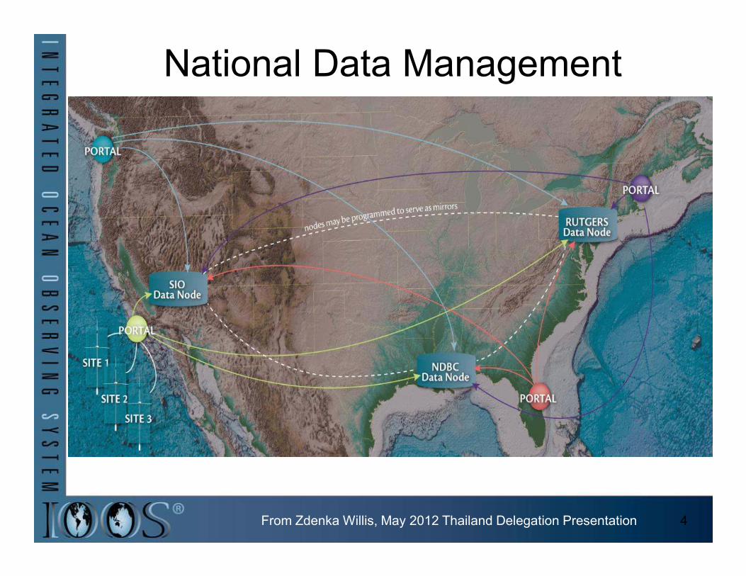
National Data Management
From Zdenka Willis, May 2012 Thailand Delegation Presentation 4
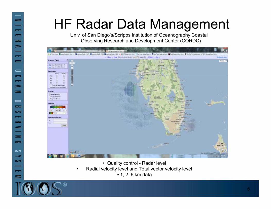
HF Radar Data ManagementUniv. of San Diego’s/Scripps Institution of Oceanography Coastal
Observing Research and Development Center (CORDC)
• Quality control - Radar level
• Radial velocity level and Total vector velocity level
• 1, 2, 6 km data
5
Existing Combined USF/CMS HF
Radar NetworkThe USF/COMPS/Ocean Circulation Group (OCG) presently operates:
• Three (3) long range CODAR (1 RX and 1 TX Antenna, Direction Finding)
systems [Redington Shores, Venice, and Naples, Florida], as well as;
• Two (2) WERA (12 RX antenna and between 1-4 TX antenna, Phased Array) systems [Ft De Soto, Venice] on the systems [Ft De Soto, Venice] on the
WFS.
• With the Venice site containing the only co-located and operational CODAR and
WERA systems in the US.
The USF CODAR HF radar systems currently operate at 4.90 MHz and the WERA HF radar systems operate
between 12.275 – 13.20 MHz, with a higher resolution coverage area within
the larger CODAR footprint.
6
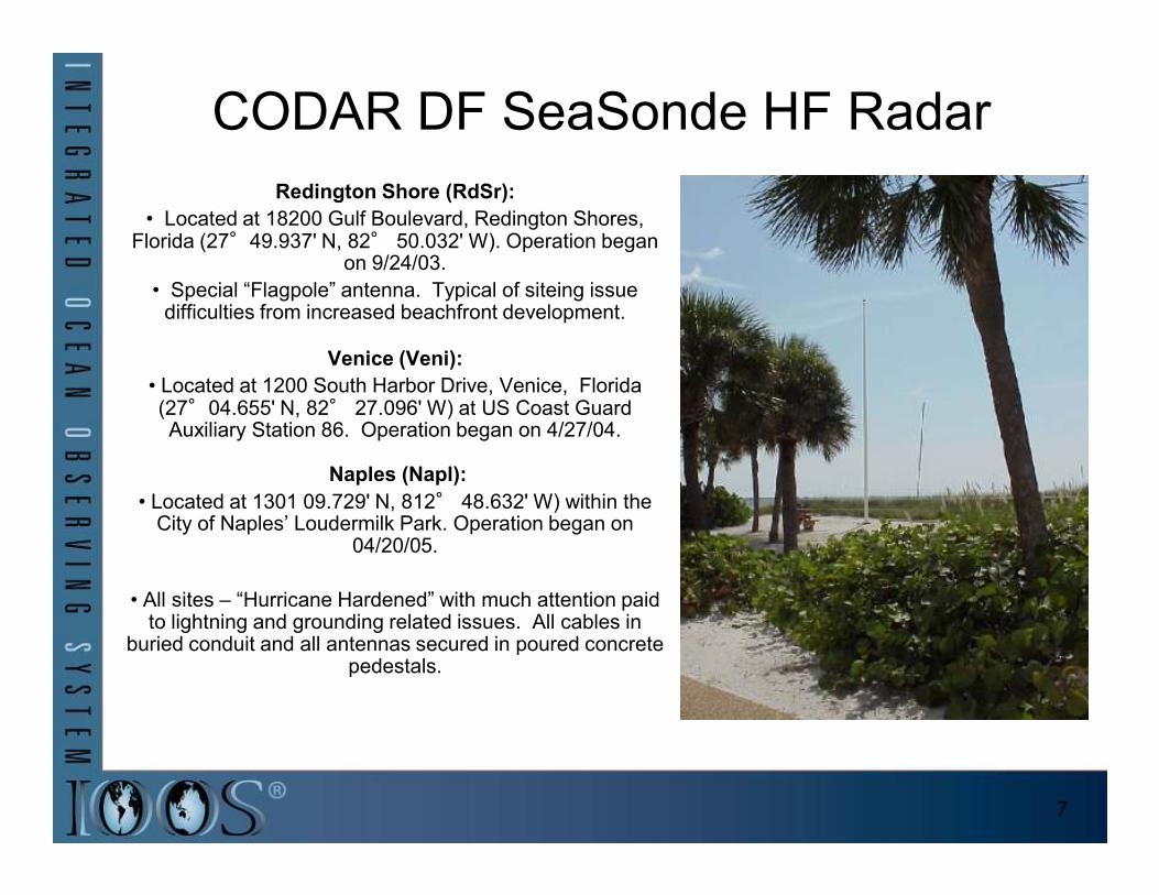
CODAR DF SeaSonde HF Radar
Redington Shore (RdSr):
• Located at 18200 Gulf Boulevard, Redington Shores, Florida (27°49.937' N, 82° 50.032' W). Operation began
on 9/24/03.
• Special “Flagpole” antenna. Typical of siteing issue difficulties from increased beachfront development.
Venice (Veni):
• Located at 1200 South Harbor Drive, Venice, Florida (27°04.655' N, 82° 27.096' W) at US Coast Guard Auxiliary Station 86. Operation began on 4/27/04.
Naples (Napl):
• Located at 1301 09.729' N, 812° 48.632' W) within the City of Naples’ Loudermilk Park. Operation began on
04/20/05.
• All sites – “Hurricane Hardened” with much attention paid to lightning and grounding related issues. All cables in
buried conduit and all antennas secured in poured concrete pedestals.
7
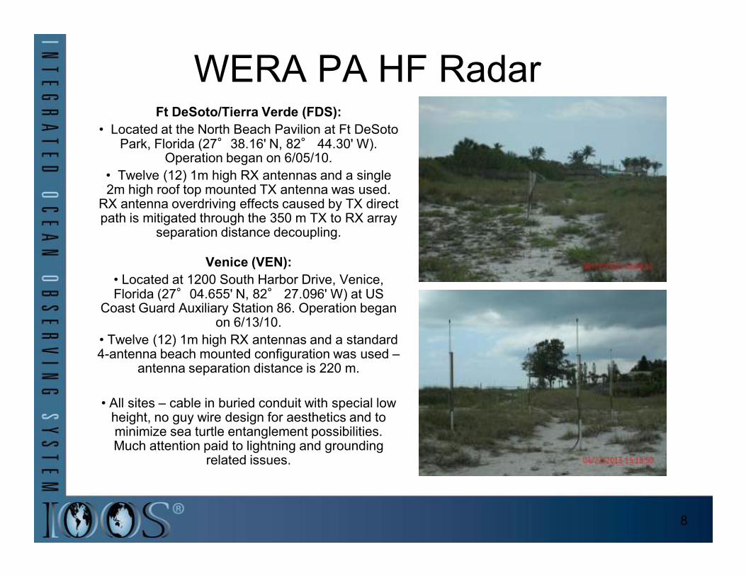
WERA PA HF RadarFt DeSoto/Tierra Verde (FDS):
• Located at the North Beach Pavilion at Ft DeSoto Park, Florida (27°38.16' N, 82° 44.30' W).
Operation began on 6/05/10.
• Twelve (12) 1m high RX antennas and a single 2m high roof top mounted TX antenna was used.
RX antenna overdriving effects caused by TX direct path is mitigated through the 350 m TX to RX array
separation distance decoupling.
Venice (VEN):
• Located at 1200 South Harbor Drive, Venice, Florida (27°04.655' N, 82° 27.096' W) at US Florida (27°04.655' N, 82° 27.096' W) at US
Coast Guard Auxiliary Station 86. Operation began on 6/13/10.
• Twelve (12) 1m high RX antennas and a standard 4-antenna beach mounted configuration was used –
antenna separation distance is 220 m.
• All sites – cable in buried conduit with special low height, no guy wire design for aesthetics and to minimize sea turtle entanglement possibilities. Much attention paid to lightning and grounding
related issues.
8
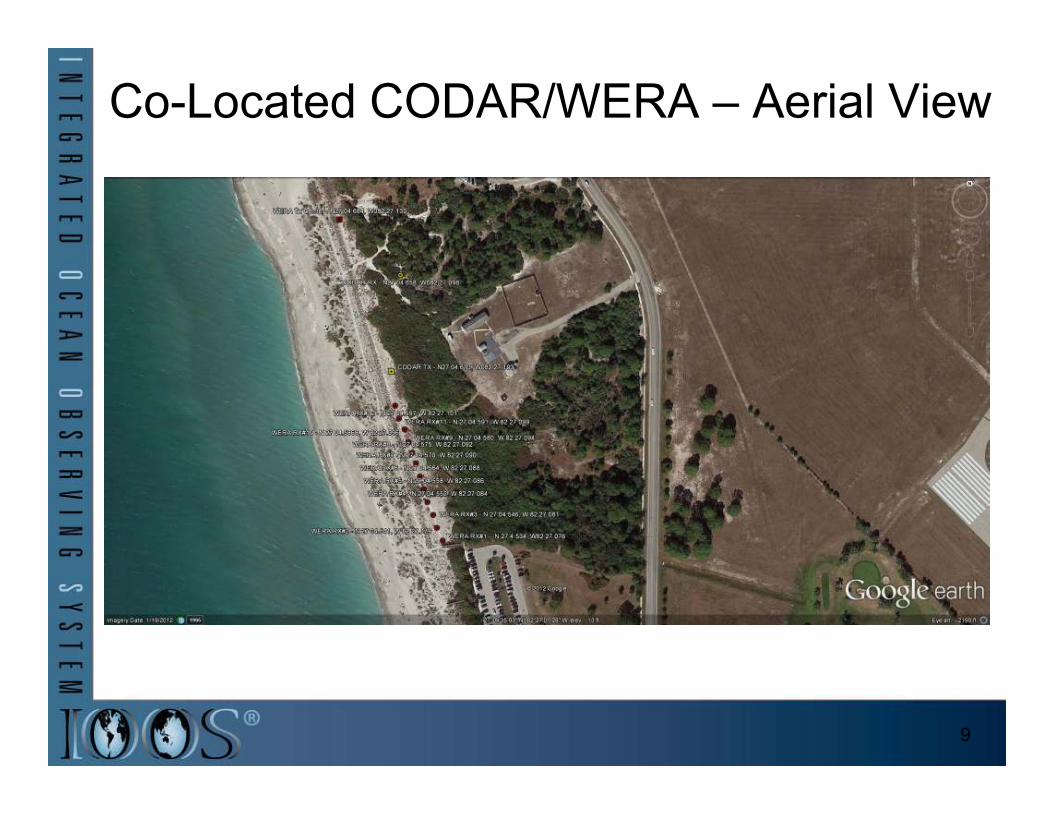
Co-Located CODAR/WERA – Aerial View
9
Co-Located CODAR/WERA
• Both systems operate on same site but at different
frequencies.
• Notch filters are placed on the WERA RX channel input locations to remove any in-
band signal issues.band signal issues.
•The included image shows the relative positions of the CODAR TX antenna (taller) and WERA RX antennas 11
and 12.
10
Real-Time Performance – Sample
CODAR Surface Current Field• HF Radar observational challenges on the WFS are sometimes manifested in low data returns, especially in the summer, where the low energy
environment and its corresponding lack of sufficient
wave energy in the band wave energy in the band necessary for Bragg scattering at
the selected transmitted
frequency.• However, when energy is
present like during a storm event, the returns are strong as shown
in the following plots.
11
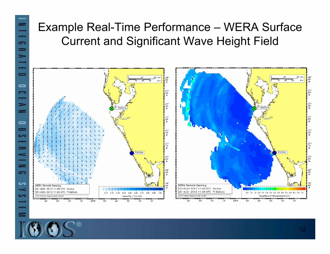
Example Real-Time Performance – WERA Surface
Current and Significant Wave Height Field
12
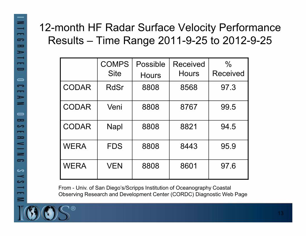
12-month HF Radar Surface Velocity Performance
Results – Time Range 2011-9-25 to 2012-9-25
COMPS
Site
Possible
Hours
Received
Hours
%
Received
CODAR RdSr 8808 8568 97.3
CODAR Veni 8808 8767 99.5
CODAR Napl 8808 8821 94.5
WERA FDS 8808 8443 95.9
WERA VEN 8808 8601 97.6
From - Univ. of San Diego’s/Scripps Institution of Oceanography Coastal
Observing Research and Development Center (CORDC) Diagnostic Web Page
13
MESOSCALE FLOW FEATURES
• HF Radar systems have been used at USF/CMS in combination with moored ADCP’s in Observing the 3-D coastal circulation on the
WFS.
• HF Radar surface current data has also been used at USF/CMS to compare with Altimetry-derived
surface currents.
• Radial currents have also been • Radial currents have also been assimilated into OCG FVCOM
Coastal Ocean circulation modeling efforts at USF/CMS.
• Can now map, quantify and track features like eddies and jets.
• Active research continues with publications cited herein.
14
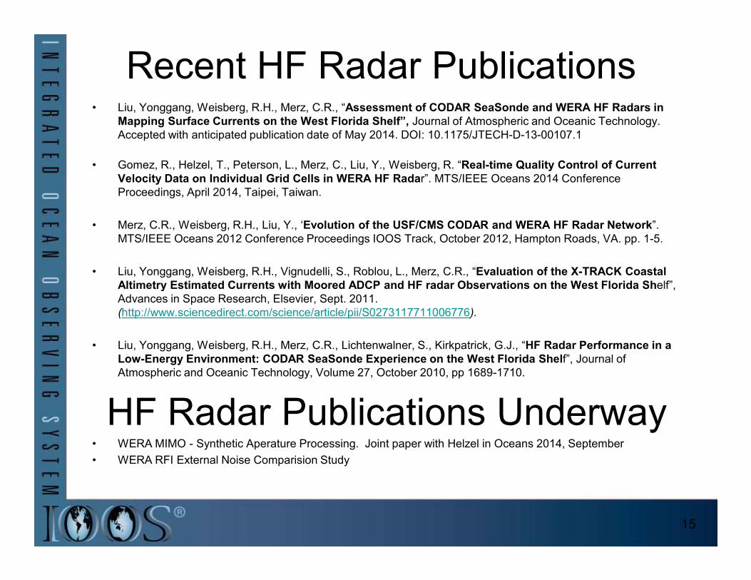
Recent HF Radar Publications• Liu, Yonggang, Weisberg, R.H., Merz, C.R., “Assessment of CODAR SeaSonde and WERA HF Radars in
Mapping Surface Currents on the West Florida Shelf”, Journal of Atmospheric and Oceanic Technology.
Accepted with anticipated publication date of May 2014. DOI: 10.1175/JTECH-D-13-00107.1
• Gomez, R., Helzel, T., Peterson, L., Merz, C., Liu, Y., Weisberg, R. “Real-time Quality Control of Current
Velocity Data on Individual Grid Cells in WERA HF Radar”. MTS/IEEE Oceans 2014 Conference
Proceedings, April 2014, Taipei, Taiwan.
• Merz, C.R., Weisberg, R.H., Liu, Y., ‘Evolution of the USF/CMS CODAR and WERA HF Radar Network”.
MTS/IEEE Oceans 2012 Conference Proceedings IOOS Track, October 2012, Hampton Roads, VA. pp. 1-5.
• Liu, Yonggang, Weisberg, R.H., Vignudelli, S., Roblou, L., Merz, C.R., “Evaluation of the X-TRACK Coastal
Altimetry Estimated Currents with Moored ADCP and HF radar Observations on the West Florida Shelf”, Altimetry Estimated Currents with Moored ADCP and HF radar Observations on the West Florida Shelf”,
• Liu, Yonggang, Weisberg, R.H., Merz, C.R., Lichtenwalner, S., Kirkpatrick, G.J., “HF Radar Performance in a
Low-Energy Environment: CODAR SeaSonde Experience on the West Florida Shelf”, Journal of
Atmospheric and Oceanic Technology, Volume 27, October 2010, pp 1689-1710.
HF Radar Publications Underway• WERA MIMO - Synthetic Aperature Processing. Joint paper with Helzel in Oceans 2014, September
• WERA RFI External Noise Comparision Study
15
Future Needs/Opportunities
• Need more HF Radar site coverage along the Gulf of Mexico region to better support:
•Ongoing Oil spill tracking and prediction efforts.
•Ongoing HAB tracking and prediction efforts.
•USCG Search and Rescue (SAR) Operations.
•Commercial and Recreational Fishing needs.•Commercial and Recreational Fishing needs.
• Expand existing USF nested CODAR/WERA HF Radar software/operational capabilities at the mouth of Tampa
Bay to include ship tracking capabilities into/ out of Tampa Bay for improved Tampa Bay Port security.
16
Thank you.
Questions?
17
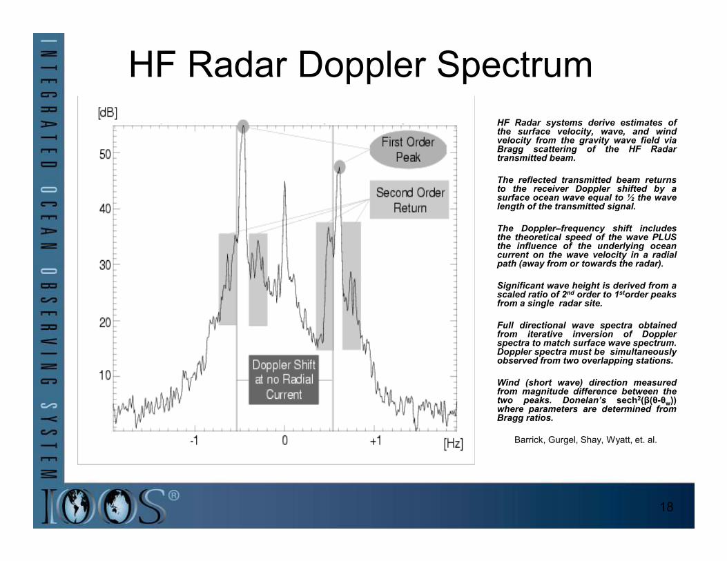
HF Radar Doppler Spectrum
HF Radar systems derive estimates ofthe surface velocity, wave, and windvelocity from the gravity wave field viaBragg scattering of the HF Radartransmitted beam.
The reflected transmitted beam returnsto the receiver Doppler shifted by asurface ocean wave equal to ½ the wavelength of the transmitted signal.
The Doppler–frequency shift includesthe theoretical speed of the wave PLUSthe influence of the underlying oceancurrent on the wave velocity in a radialpath (away from or towards the radar).
Significant wave height is derived from aSignificant wave height is derived from ascaled ratio of 2nd order to 1storder peaksfrom a single radar site.
Full directional wave spectra obtainedfrom iterative inversion of Dopplerspectra to match surface wave spectrum.Doppler spectra must be simultaneouslyobserved from two overlapping stations.
Wind (short wave) direction measuredfrom magnitude difference between thetwo peaks. Donelan’s sech2(β(θ-θw))where parameters are determined fromBragg ratios.