EVTM (ETHERNET-VIA-TELEMETRY): GET ETHERNET PACKETIZED DATA DIRECTLY FROM YOUR TEST
ARTICLE
Matt Schultz Quasonix, West Chester, OH
ABSTRACT
This article defines the system design for translating burst Ethernet packetized data into a constant rate serial data stream suitable for transmission over standard telemetry hardware physical links. The system supports both unidirectional (UDP) and bidirectional (TCP/IP, etc.) communications. This paper will evaluate the capabilities and limitations of the established fielded hardware, as well as possibilities for system growth (IRIG Chapter 10 compatibility).
KEYWORDS Wireless Ethernet, EVTM
1. INTRODUCTION
Traditionally, telemetered test data has been restricted to one way communication, with very little flexibility in the data being transferred, and almost no way to change the information on the stream in real time, or change data feed efficiently. Other programs have attempted to address the queuing of information issue, with limited success. EVTM (Ethernet-via-Telemetry) leverages existing telemetry infrastructure and aeronautical RF channels to allow bidirectional transfer of packetized data over a standard serial stream RF link. The system at either end of the link sees the EVTM as nothing more than a data transfer hub; basically a long distance Wi-Fi connection.
2. SYSTEM THEORY OF OPERATION
Encoding (Ethernet to serial stream) and decoding (serial stream to Ethernet) are done outside of the modulation and demodulation of the RF signal. On the transmit end, information is fed into a 16 kbyte FIFO buffer, and clocked out at a set data rate. On the receive end, the serial stream is fed directly into the decoder, and transferred to the Ethernet network.
2.1 ETHERNET PROTOCOL [1]
[Protocol designed by Metrodata Ltd]
The encapsulation protocol works directly on the Ethernet MAC frame with no understanding of any higher protocol layers such as IP. The Ethernet frame definition is described in Figure 1.
Preamble 7 Bytes
SFD Start of Frame Delimiter 1 Byte
2
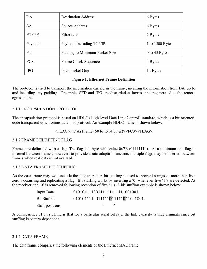
DA Destination Address 6 Bytes
SA Source Address 6 Bytes
ETYPE Ether type 2 Bytes
Payload Payload, Including TCP/IP 1 to 1500 Bytes
Pad Padding to Minimum Packet Size 0 to 45 Bytes
FCS Frame Check Sequence 4 Bytes
IPG Inter-packet Gap 12 Bytes
Figure 1: Ethernet Frame Definition
The protocol is used to transport the information carried in the frame, meaning the information from DA, up to and including any padding. Preamble, SFD and IPG are discarded at ingress and regenerated at the remote egress point. 2.1.1 ENCAPSULATION PROTOCOL
The encapsulation protocol is based on HDLC (High-level Data Link Control) standard, which is a bit-oriented, code transparent synchronous data link protocol. An example HDLC frame is shown below:
<FLAG>< Data Frame (60 to 1514 bytes)><FCS><FLAG>
2.1.2 FRAME DELIMITING FLAG
Frames are delimited with a flag. The flag is a byte with value 0x7E (01111110). At a minimum one flag is inserted between frames; however, to provide a rate adaption function, multiple flags may be inserted between frames when real data is not available.
2.1.3 DATA FRAME BIT STUFFING
As the data frame may well include the flag character, bit stuffing is used to prevent strings of more than five zero’s occurring and replicating a flag. Bit stuffing works by inserting a ‘0’ whenever five ‘1’s are detected. At the receiver, the ‘0’ is removed following reception of five ‘1’s. A bit stuffing example is shown below:
Input Data 01010111100111111111111001001
Bit Stuffed 0101011110011111011111011001001
Stuff positions ^ ^
A consequence of bit stuffing is that for a particular serial bit rate, the link capacity is indeterminate since bit stuffing is pattern dependent.
2.1.4 DATA FRAME
The data frame comprises the following elements of the Ethernet MAC frame
3
DA, SA, ETYPE, PAYLOAD, PAD
The data frame is subject to bit stuffing to ensure that the flag pattern is not replicated.
2.1.5 FRAME CHECK SEQUENCE
To enable error detection, rather than calculating a new FCS, the Ethernet frame CRC-32 MAC FCS is used directly and transmitted following the data frame.
The receiver checks the CRC-32 and if an error is detected the frame is discarded.
A frame with a good FCS is de-capsulated ready for transmission on the LAN.
If necessary, the FCS is also bit stuffed.
The CRC-32 polynomial is as below:
X32+X26+X23+X22+X16+X12+X11+X10+X8+X7+X5+X4+X2+X
2.1.6 BIT ORDER
HDLC Data is transmitted un-encoded over the serial port in the order that it is received on the LAN port.
2.2 PHYSICAL LAYER
The serial interface is very similar to standard telemetry serial signalling. The synchronous clock and data streams are rising edge transition and falling edge data read. There is an additional signal on the transmit side, that sets the data rate of the transmitter, rather than auto-scaling from the synchronous clock as in a standard SST (Serial Streaming Telemetry) system. The use of an IRIG randomizer is recommended, as HDLC idle patterns are not random enough to keep the RF signal symmetric.
Additionally, because the Ethernet-to-serial encoding and decoding is done at the serial stream level, it does not preclude the use of any signalling technique. Any approved modulation can be used (PCM/FM, SOQPSK-TG and Multi-h CPM). In addition, any of the standard modifiers (LDPC Forward Error Correction, Space Time Coding, etc.) can also be used.
2.2.1 SYSTEM BLOCK DIAGRAM
The system shown in Figure 2 shows the signalling for a bi-directional, dual simplex, frequency diverse EVTM data link.
4
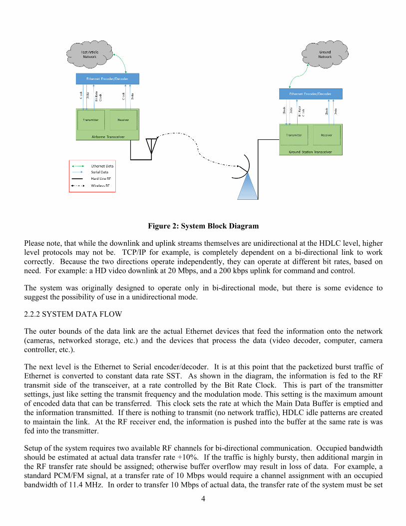
Figure 2: System Block Diagram
Please note, that while the downlink and uplink streams themselves are unidirectional at the HDLC level, higher level protocols may not be. TCP/IP for example, is completely dependent on a bi-directional link to work correctly. Because the two directions operate independently, they can operate at different bit rates, based on need. For example: a HD video downlink at 20 Mbps, and a 200 kbps uplink for command and control.
The system was originally designed to operate only in bi-directional mode, but there is some evidence to suggest the possibility of use in a unidirectional mode.
2.2.2 SYSTEM DATA FLOW
The outer bounds of the data link are the actual Ethernet devices that feed the information onto the network (cameras, networked storage, etc.) and the devices that process the data (video decoder, computer, camera controller, etc.).
The next level is the Ethernet to Serial encoder/decoder. It is at this point that the packetized burst traffic of Ethernet is converted to constant data rate SST. As shown in the diagram, the information is fed to the RF transmit side of the transceiver, at a rate controlled by the Bit Rate Clock. This is part of the transmitter settings, just like setting the transmit frequency and the modulation mode. This setting is the maximum amount of encoded data that can be transferred. This clock sets the rate at which the Main Data Buffer is emptied and the information transmitted. If there is nothing to transmit (no network traffic), HDLC idle patterns are created to maintain the link. At the RF receiver end, the information is pushed into the buffer at the same rate is was fed into the transmitter.
Setup of the system requires two available RF channels for bi-directional communication. Occupied bandwidth should be estimated at actual data transfer rate +10%. If the traffic is highly bursty, then additional margin in the RF transfer rate should be assigned; otherwise buffer overflow may result in loss of data. For example, a standard PCM/FM signal, at a transfer rate of 10 Mbps would require a channel assignment with an occupied bandwidth of 11.4 MHz. In order to transfer 10 Mbps of actual data, the transfer rate of the system must be set
5
10% over to account for the encoding. This would bring the required RF rate to the equivalent of 11 Mbps, with an occupied bandwidth of 12.54 MHz.
3. FIRST ARTICLE EVALUATION AND FLIGHT TESTING
The first systems were delivered and evaluated by two installations. The system delivered to NASA Armstrong Flight Research Center was thoroughly evaluated for functionality in a lab environment. Experiments were performed to determine system capabilities and shortfalls, and will be described later in this document. The second system was evaluated, and flown with live data at Redstone Army Test Center. The test conditions and results from this installation will also be presented. 3.1 LAB EVALUATION PERFORMED AT NASA ARMSTRONG FLIGHT RESEARCH CENTER. 3.1.1 LAB SETUP The lab set up of EVTM can be seen in Figure 3:
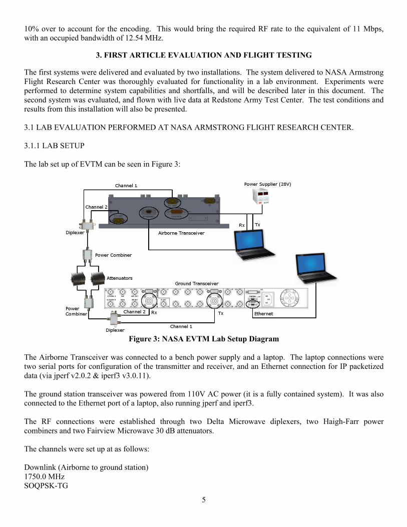
Figure 3: NASA EVTM Lab Setup Diagram
The Airborne Transceiver was connected to a bench power supply and a laptop. The laptop connections were two serial ports for configuration of the transmitter and receiver, and an Ethernet connection for IP packetized data (via jperf v2.0.2 & iperf3 v3.0.11). The ground station transceiver was powered from 110V AC power (it is a fully contained system). It was also connected to the Ethernet port of a laptop, also running jperf and iperf3. The RF connections were established through two Delta Microwave diplexers, two Haigh-Farr power combiners and two Fairview Microwave 30 dB attenuators. The channels were set up at as follows: Downlink (Airborne to ground station) 1750.0 MHz SOQPSK-TG
6
Uplink (Ground station to airborne) 2217.5 MHz SOQPSK-TG Tests were performed at six different data rates: 1 Mbps (1.3 Mbps transfer rate) 4 Mbps (5 Mbps transfer rate) 8 Mbps (10 Mbps transfer rate)
12 Mbps (15 Mbps transfer rate) 15 Mbps (18.75 Mbps transfer rate) 16 Mbps (20 Mbps transfer rate)
3.1.2 FIRST ATTEMPT TEST RESULTS [From Ethernet via Telemetry (EVTM) Lab Report] “EVTM was first tested using procedure #1 without diplexers and power combiners, then repeated the same
procedure except both laptops reversed their roles (i.e. airborne laptop changed from server to client and
ground laptop changed from client to server) in order to see if the role of client/server on the airborne laptop
and the ground laptop have any significant impact on performance.
Airborne – Server, Ground – Client (Dec 18) link rate in Mbps
1200 B
4 KB
1 (1.3) 0.45% 0% 4 (5) 0% 0.027
% 8 (10) 0.048
% 21%
12 (15) 21% 47% 15
(18.75) 24% 44%
16 (20) 28% 47%
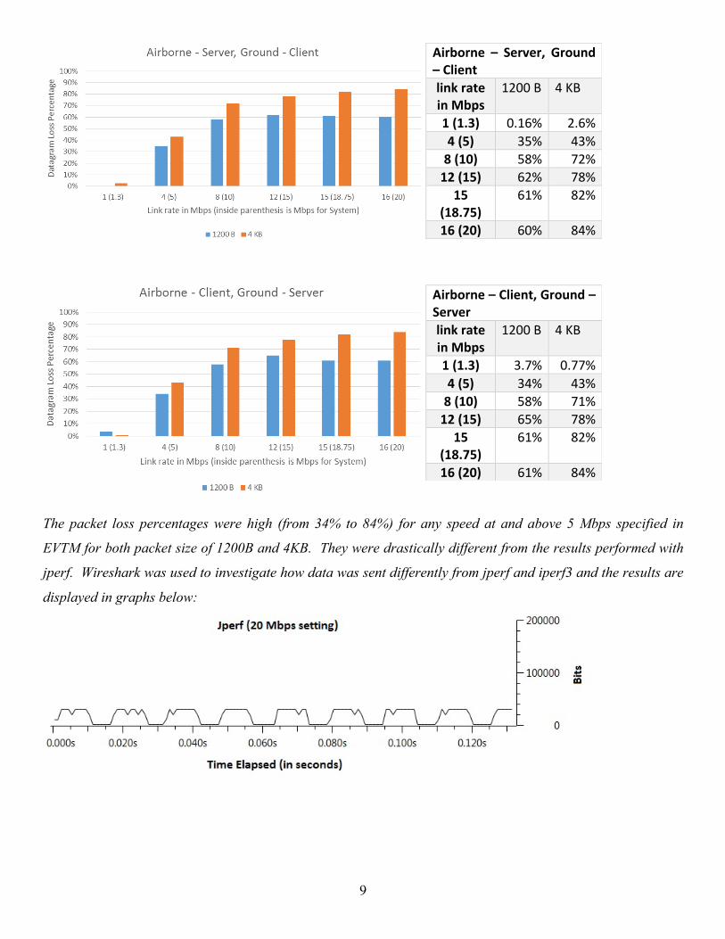
The graph along with the data above is from the test performed on December 18, 2014, with the
airborne laptop acting as server and the ground laptop acting as client. The number inside the parenthesis in
“link rate in Mbps” section is the bandwidth specified in EVTM while the number outside of parenthesis is the
link rate specified in jperf. The number outside of the parenthesis is 80% of the bandwidth and the remaining
20% left is to account for the overhead. Packets with the size of 1200B have higher loss percentage at the rate
of equal to or greater than 12 Mbps link rate, and the packet size of 4KB have higher loss percentage at the rate
of equal to or greater than 8 Mbps link rate.
7
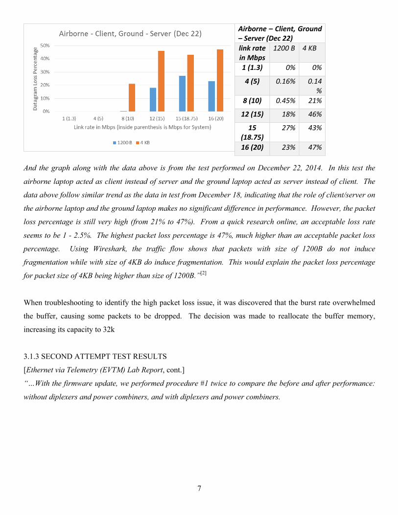
Airborne – Client, Ground – Server (Dec 22) link rate in Mbps
1200 B 4 KB
1 (1.3) 0% 0%
4 (5) 0.16% 0.14%
8 (10) 0.45% 21%
12 (15) 18% 46%
15 (18.75)
27% 43%
16 (20) 23% 47%
And the graph along with the data above is from the test performed on December 22, 2014. In this test the
airborne laptop acted as client instead of server and the ground laptop acted as server instead of client. The
data above follow similar trend as the data in test from December 18, indicating that the role of client/server on
the airborne laptop and the ground laptop makes no significant difference in performance. However, the packet
loss percentage is still very high (from 21% to 47%). From a quick research online, an acceptable loss rate
seems to be 1 - 2.5%. The highest packet loss percentage is 47%, much higher than an acceptable packet loss
percentage. Using Wireshark, the traffic flow shows that packets with size of 1200B do not induce
fragmentation while with size of 4KB do induce fragmentation. This would explain the packet loss percentage
for packet size of 4KB being higher than size of 1200B.”[2]
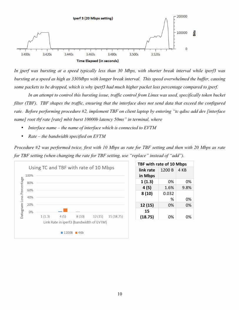
When troubleshooting to identify the high packet loss issue, it was discovered that the burst rate overwhelmed
the buffer, causing some packets to be dropped. The decision was made to reallocate the buffer memory,
increasing its capacity to 32k
3.1.3 SECOND ATTEMPT TEST RESULTS
[Ethernet via Telemetry (EVTM) Lab Report, cont.]
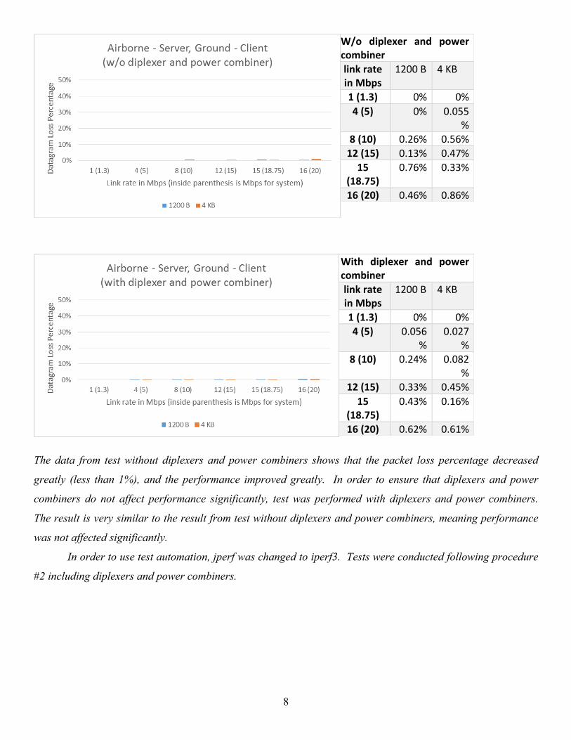
“…With the firmware update, we performed procedure #1 twice to compare the before and after performance:
without diplexers and power combiners, and with diplexers and power combiners.
8
W/o diplexer and power combiner link rate in Mbps
1200 B 4 KB
1 (1.3) 0% 0% 4 (5) 0% 0.055
% 8 (10) 0.26% 0.56% 12 (15) 0.13% 0.47% 15
(18.75) 0.76% 0.33%
16 (20) 0.46% 0.86%
With diplexer and power combiner link rate in Mbps
1200 B 4 KB
1 (1.3) 0% 0% 4 (5) 0.056
% 0.027
% 8 (10) 0.24% 0.082
% 12 (15) 0.33% 0.45% 15
(18.75) 0.43% 0.16%
16 (20) 0.62% 0.61%
The data from test without diplexers and power combiners shows that the packet loss percentage decreased
greatly (less than 1%), and the performance improved greatly. In order to ensure that diplexers and power
combiners do not affect performance significantly, test was performed with diplexers and power combiners.
The result is very similar to the result from test without diplexers and power combiners, meaning performance
was not affected significantly.
In order to use test automation, jperf was changed to iperf3. Tests were conducted following procedure
#2 including diplexers and power combiners.
9
Airborne – Server, Ground – Client link rate in Mbps
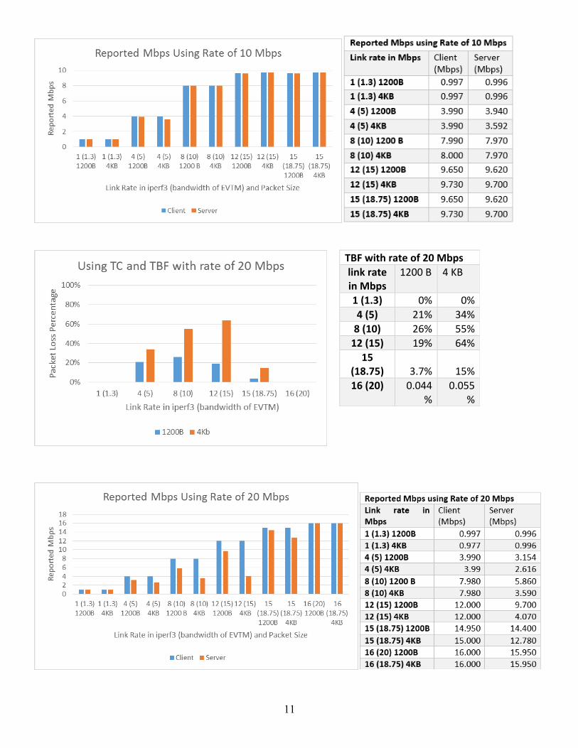
According to the results above, traffic control using TBF did reduce the packet loss percentage for the rate
established in TBF implementation, however, there are still some packet loss percentage at speed less than the
rate. This issue is still being investigated. The results above suggest that using switch to shape traffic may be
one of solutions for reducing dropped packets.”[2]
3.2 FLIGHT TEST PERFORMED AT REDSTONE ARSENAL
3.2.1 TEST SETUP
Aircraft antenna: Haigh-Farr Model 6130 (omnidirectional)
Base Station antenna: Antenna.us model UL-235A-498 (directional)
Data Rate: ≈9.0 Mbps
Link Distance: 4 km and 8 km
Modulation: SOQPSK-TG
Frequency: S-band 2.2 to 2.5 GHz
3.2.2 TEST RESULTS
On the 4 km link, a file transfer speed test was performed, which peaked at around 9 Mbps. There was also a
monitoring of remote equipment which maintained a consistent link. On the 8 km link, only the monitoring of
remote equipment was performed, with very similar results. Both links were encrypted at the Ethernet input
(before transfer to the EVTM system).
4. LESSONS LEARNED/FUTURE DEVELOPMENT
4.1 PACKET LOSS EVALUATION Two major elements contributed to the high packet loss rates measured at NASA. First was the under-sized data buffers. The total available memory for data buffering was only 16 kB in each direction. The first implementation actually had the memory split between transmit and receive paths on the encoder/decoder boards. The design was originally supposed to be one board that handled bi-directional traffic with one device. The final hardware configuration actually split the encoding/decoding to two boards; one on the transmitter and one on the receiver. The firmware was updated to push all the memory to the used (transmit/receive) side, effectively doubling the available memory for each direction. Second, it was observed that a standard connection does not default to enable flow control. It will attempt to transfer all the data in as short a period as possible. Attempting to enter data into the buffer at a rate greater than the encoder drains it will result in data overflows for sufficiently large files. Most Windows-based machines do not allow for flow control. A Linux-based machine will allow for a flow control, causing the machine to meter out the data at a more digestible rate.
13
4.2 REDSTONE FLIGHT OBSERVATIONS Much of the information about the actual flight and the data transferred is still restricted to official use. With the information that is able to be released, there are a few conclusions to be made. The encoding/decoding had zero issues dealing with encryption. For as long as the RF link is maintained, a TCP/IP data stream will operate normally. 4.3 NEXT GENERATION IMPROVEMENTS Currently the second generation EVTM encoder/decoder is in redesign. There have been changes made to the hardware to account for manufacturability, as well as flexibility. One of the biggest changes directly addresses the buffer size. New hardware will expand the buffer from 32 Kbytes to 1 Mbyte. This should be enough space to handle data rates up to 46 Mbps, the current maximum achievable rate for SOQPSK. Another desirable change will come in the form of changing the RF link from frequency diverse system to a time diverse system. A time diverse system will reduce the required bandwidth by eliminating the need to assign a separate uplink and downlink channel. The time diverse capability is expected to be available late 2016/early 2017. The only live flight scenario that has been performed to date (Redstone) has been done with antennas not connected to LNAs and not connected to tracking systems. It is assumed that other established programs (iNet) may have requirements for running time division multiplex two-way links. These requirements necessitate the establishment of a method of a return RF path through tracking antennas, technology that can be leveraged for the operation of EVTM hardware. We anticipate compatibility with auto tracking ACUs, as the receiver and demodulator hardware is unmodified from current fielded hardware. The major unresolved issue is the return RF path. Equipment designed to support bi-directional RF links will need to have this addressed, as well as where the T/R switch is controlled.
5. CONCLUSION By adding another layer between the transmitter and receiver at the data input or output point, it is possible to transfer Ethernet packetized data with existing aeronautical telemetry hardware. Early testing has shown the technology to be viable, but has revealed shortcomings. These shortcomings are not unsurmountable, and some are already being addressed.
6. REFERENCES
[1] Banbrook, Ian, "Ethernet Over Serial Link Protocol Specification", Metrodata Ltd., Fortune House, Crabtree Office Village, Eversley Way, Egham Surrey, TW20 8RY, UK, April 2014
[2] Lucht, Johanna.” "Ethernet via Telemetry (EVTM) Lab Report", NASA Armstrong Flight Research Center, Edwards, CA, USA, 2015.