ENMET Corporation PO Box 979 Ann Arbor, MI 48106-0979 www.enmet.com Manual Part Number 80003-122 MCN-14-001, 01/22/14 EX-6100 COMBUSTIBLE GAS SENSOR/TRANSMITTER With Pellistor/Catalytic Type Sensor Manual
Transcript
ENMET Corporation PO Box 979 Ann Arbor, MI 48106-0979 www.enmet.com
Manual Part Number 80003-122
MCN-14-001, 01/22/14
EX-6100 COMBUSTIBLE GAS SENSOR/TRANSMITTER
With Pellistor/Catalytic Type Sensor Manual
Table of Contents 1.0 INTRODUCTION ......................................................................................................................................................................................... 1
1.1 UNPACK .................................................................................................................................................................................................. 1 1.2 CHECK ORDER ......................................................................................................................................................................................... 1 1.3 SERIAL NUMBERS ..................................................................................................................................................................................... 1
2.0 FEATURES OF THE EX-6100..................................................................................................................................................................... 2 3.0 INSTALLATION OF THE EX-6100 ................... ........................................................................................................................................... 3
3.1 MOUNTING THE EX-6100 ENCLOSURE ....................................................................................................................................................... 3 3.2 WIRING THE EX-6100 TO A CONTROL UNIT ................................................................................................................................................ 4 3.2 POWER SUPPLY ....................................................................................................................................................................................... 5 3.3 ANALOGUE OUTPUT ................................................................................................................................................................................. 5 3.4 RS232 OUTPUT ....................................................................................................................................................................................... 5 3.5 FOLLOWING COMPLETION OF THE INSTALLATION: ........................................................................................................................................ 6 3.6 APPLYING POWER..................................................................................................................................................................................... 6 3.7 INDICATORS ............................................................................................................................................................................................. 6
A.4 FRAME STRUCTURE ............................................................................................................................................................................... 21 A.4.1 Variables............................................................................................................................................................................................................................. 21 A.4.2 Reading a Variable ............................................................................................................................................................................................................. 22 A.4.3 Read example - read live data ........................................................................................................................................................................................... 22
A.4.4 WRITING A VARIABLE ........................................................................................................................................................................... 22 WARRANTY .......................................... ......................................................................................................................................................... 23
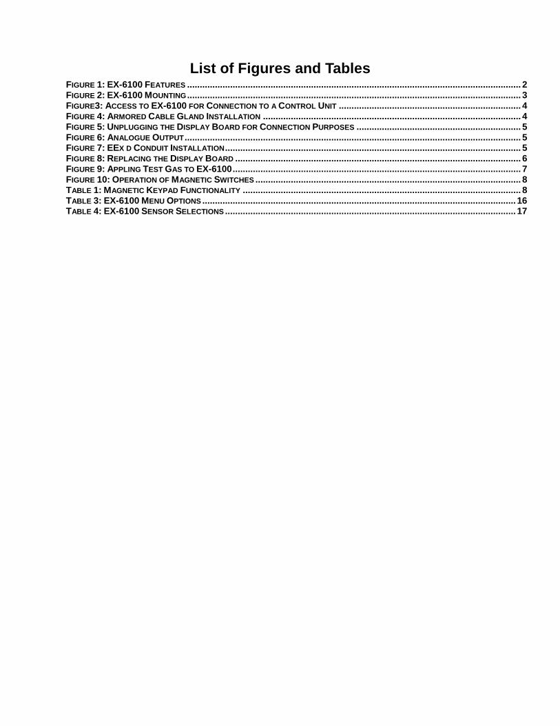
List of Figures and Tables FIGURE 1: EX-6100 FEATURES .................................................................................................................................... 2 FIGURE 2: EX-6100 MOUNTING .................................................................................................................................... 3 FIGURE3: ACCESS TO EX-6100 FOR CONNECTION TO A CONTROL UNIT ........................................................................ 4 FIGURE 4: ARMORED CABLE GLAND INSTALLATION ...................................................................................................... 4 FIGURE 5: UNPLUGGING THE DISPLAY BOARD FOR CONNECTION PURPOSES ................................................................. 5 FIGURE 6: ANALOGUE OUTPUT ..................................................................................................................................... 5 FIGURE 7: EEX D CONDUIT INSTALLATION ..................................................................................................................... 5 FIGURE 8: REPLACING THE DISPLAY BOARD ................................................................................................................. 6 FIGURE 9: APPLING TEST GAS TO EX-6100 .................................................................................................................. 7 FIGURE 10: OPERATION OF MAGNETIC SWITCHES ......................................................................................................... 8 TABLE 1: MAGNETIC KEYPAD FUNCTIONALITY .............................................................................................................. 8 TABLE 3: EX-6100 MENU OPTIONS ............................................................................................................................ 16 TABLE 4: EX-6100 SENSOR SELECTIONS ................................................................................................................... 17
ENMET Corporation EX-6100
1
1.0 Introduction The ENMET EX-6100 Fixed Gas Detectors for the detection of Flammable gases is ATEX Flameproof Certified for use in Group IIC hazardous locations. Directive 94/9/EC ATEX and the equivalent rating of Class1, Division 1, Groups A, B, C and D
Harmonised Standards Used:
EN60079-0:2006 Electrical apparatus for explosive gas atmospheres – Part 0: General requirements. EN60079-1:2007 Explosive atmospheres – Part 1: Equipment protection by flameproof enclosures “d”.
Notified Body for Hazardous Area Certification:
SIRA Certification Service Rake Lane, Eccleston, Chester, CH4 9JN. Notified Body Number : 0518
Notified Body for ATEX Quality Assurance Notificati on:
Baseefa Rockhead Business Park Staden Lane, Buxton SK17 9RZ, UK Notified Body Number : 1180
Hazardous Area Certificate Number:
SIRA 08ATEX1031X II 2 G Ex d IIC T4 (Ta = -20OC + 60 OC ) T5 (Ta = -20OC + 50 OC ) T6 (Ta = -20OC + 35 OC )
ATEX Quality Assurance Notification Number:
2056
NOTE: All specifications stated in this manual may change without notice.
1.1 Unpack Unpack the EX-6100 and examine it for shipping damage. If such damage is observed, notify both ENMET customer service personnel and the commercial carrier involved immediately.
Regarding Damaged Shipments NOTE: It is your responsibility to follow these instructions. If they are not followed, the carrier will not honor any claims for damage. � This shipment was carefully inspected, verified and properly packaged at our company and delivered to the carrier in
good condition.
� When it was picked up by the carrier at ENMET, it legally became your company’s property.
� If your shipment arrives damaged:
• Keep the items, packing material, and carton “As Is.” Within 5 days of receipt, notify the carrier’s local office and request immediate inspection of the carton and the contents.
• After the inspection and after you have received written acknowledgment of the damage from the carrier, contact ENMET Customer Service for return authorization and further instructions. Have your Purchase Order and Sales Order numbers available.
� ENMET either repairs or replaces damaged equipment and invoices the carrier to the extent of the liability coverage, usually $100.00. Repair or replacement charges above that value are your company’s responsibility.
� The shipping company may offer optional insurance coverage. ENMET only insures shipments with the shipping company when asked to do so in writing by our customer. If you need your shipments insured, please forward a written request to ENMET Customer Service.
Regarding Shortages If there are any shortages or questions regarding this shipment, please notify ENMET Customer Service within 5 days of receipt at the following address:
ENMET Corporation 680 Fairfield Court
Ann Arbor, MI 48108 734-761-1270 734-761-3220 Fax
1.2 Check Order Check, the contents of the shipment against the purchase order. Verify that the EX-6100 is received as ordered. [Each EX-6100 is labeled with its target gas.] If there are accessories on the order, ascertain that they are present. Check the contents of calibration kits. Notify ENMET customer service personnel of any discrepancy immediately.
1.3 Serial Numbers Each EX-6100 is serialized. These numbers are on tags on the equipment and are on record in an ENMET database.
EX-6100 ENMET Corporation
2
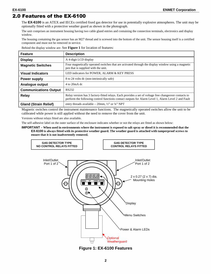
2.0 Features of the EX-6100 The EX-6100 is an ATEX and IECEx certified fixed gas detector for use in potentially explosive atmospheres. The unit may be optionally fitted with a protective weather guard as shown in the photograph. The unit comprises an instrument housing having two cable gland entries and containing the connection terminals, electronics and display window.
The housing containing the gas sensor has an M27 thread and is screwed into the bottom of the unit. The sensor housing itself is a certified component and must not be removed in service.
Behind the display window are- See Figure 1 for location of features:
Feature Description
Display A 4-digit LCD display
Magnetic Switches Four magnetically operated switches that are activated through the display window using a magnetic pen that is supplied with the unit.
Visual Indicators LED indicators for POWER, ALARM & KEY PRESS
Power supply 8 to 24 volts dc (non-intrinsically safe)
Analogue output 4 to 20mA dc
Communications Output RS232
Relay Relay version has 3 factory-fitted relays. Each provides a set of voltage free changeover contacts to perform the following control functions contact outputs for Alarm Level 1, Alarm Level 2 and Fault
Gland (Strain Relief) entry threads available – 20mm, ½” or ¾” NPT
Magnetic switches control the instrument maintenance functions. The magnetically operated switches allow the unit to be calibrated while power is still applied without the need to remove the cover from the unit. Versions without relays fitted are also available. The self-adhesive label on the outer surface of the enclosure indicates whether or not the relays are fitted as shown below:
IMPORTANT – When used in environments where the instrument is exposed to salt spray or diesel it is recommended that the EX-6100 is always fitted with its protective weather guard. The weather guard is attached with tamperproof screws to ensure that it is not inadvertently removed.
Figure 1: EX-6100 Features
GAS DETECTOR TYPE CONTROL RELAYS FITTED
GAS DETECTOR TYPE NO CONTROL RELAYS FITTED
2 x 0.27 (2 x 7) dia. Mounting Holes
Optional Weatherguard
Inlet/Outlet Port 1 of 2
Display
Menu Switches
Power & Alarm LEDs
Inlet/Outlet Port 1 of 2
MENU UP DOWN ENTER
EX-6100 ENMET Corporation
3
3.0 Installation of the EX-6100 CAUTION: Area must be declassified during installation.
The EX-6100 gas sensor/transmitter (S/T) is a 3-wire, 24 VDC 4-20 mA S/T for the detection of combustible gas. The S/T is meant to be used in conjunction with an appropriate power supply and controller. The EX-6100 sensor/transmitter is in an enclosure rated for use in a ATEX and IIC, Class I, Division 1, Groups B, C, D, classified area. Appropriate wiring, conduit and fittings are required for proper installation in a explosion proof rated environment.
CAUTION: Since the sensor/transmitter detects gas only at the sensor location, pay attention to the possible sources of gas, the density of the gas, locations where the gas may be confined and locations where the gas may damage or injure property or personnel, when choosing locations of sensor/transmitters.
Take into consideration environmental factors when deciding on S/T location. Avoid locations where the S/T may be damaged by liquid immersion, excessive heat or other known hazards. Also, take precautions to insure condensation inside of the conduit does not enter the S/T.
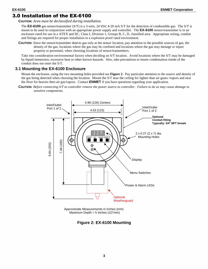
3.1 Mounting the EX-6100 Enclosure Mount the enclosure, using the two mounting holes provided see Figure 2. Pay particular attention to the source and density of the gas being detected when choosing the location. Mount the S/T near the ceiling for lighter than air gases /vapors and near the floor for heavier then air gas/vapors. Contact ENMET if you have questions regarding your application.
CAUTION: Before connecting S/T to controller remove the power source to controller. Failure to do so may cause damage to sensitive components.
Figure 2: EX-6100 Mounting
Approximate Measurements in Inches (mm) Maximum Depth = 5 Inches (127mm)
3.2 Wiring the EX-6100 to a Control Unit CAUTION: Area must be declassified during installation.
If the EX-6100 is installed in a hazardous location as defined by the National Electrical Code, then ALL wiring must be in accordance with the National code and any local governing codes.
Open the enclosure, and remove the 2 screws that retain the display overlay to the circuit board.
Turn cover securing stud counter-clockwise to allow cover to open.
Remove cover by rotating counter-clockwise.
Figure3: Access to EX-6100 for Connection to a Cont rol Unit The cable entry threads are 20mm, ½” or ¾” NPT female.
The EX-6100 enclosure is manufactured from die cast aluminum*. Therefore, the use of glands, conduit fittings and blanks made from brass should be avoided because if moisture is present, bi-metallic corrosion may occur due to the chemical reaction between the two materials.
Glands and fittings plated with nickel, tin or zinc will provide improved protection but in harsh environments the use of stainless steel is recommended.
Figure 4: Armored Cable Gland Installation Relays - three relays are provided:
Alarm 1 and Alarm 2 are associated with the alarm points.
Alarm 3 is associated with fault conditions.
All relays are factory set to de-energize state non alarm.
EX-6100 ENMET Corporation
5
Figure 5: Unplugging the Display Board for Connecti on Purposes 3.2 Power Supply
The EX-6100 is powered from an 8 – 24 volt dc, 5 W maximum output supply. This may be either:-
a) An independent supply powering one or more units.
b) A supply that is an integral part of a control card within a monitoring panel.
3.3 Analogue Output The analogue output provides a means of indicating to external equipment (e.g. data loggers, remote displays, control cards) the gas levels currently being detected by the system. The output is in the form of the industry standard 4 to 20mA current source.
The analogue output is factory set such that 4mA represents zero gas and 20mA represents the full scale gas level of the EX-6100.
Figure 6: Analogue Output 3.4 RS232 Output
This output is designed to be compatible with a PC fitted with an RS232 serial communications port. Suitable software is available for installation in the PC. Contact ENMET Corporation for details.
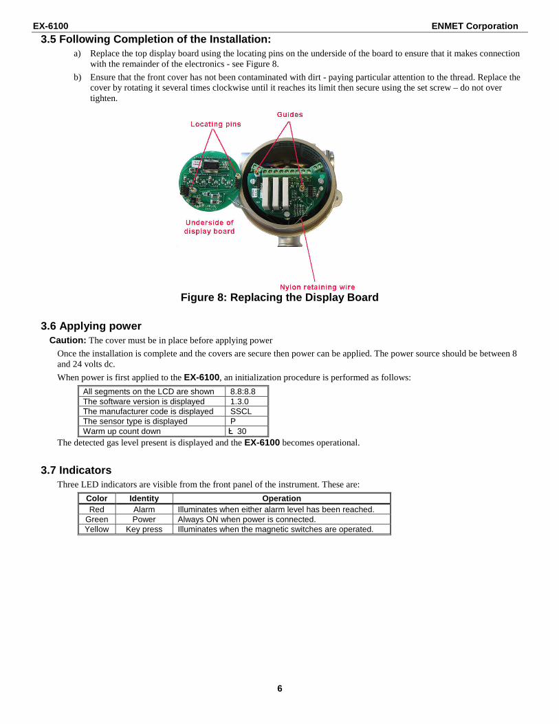
3.5 Following Completion of the Installation: a) Replace the top display board using the locating pins on the underside of the board to ensure that it makes connection
with the remainder of the electronics - see Figure 8.
b) Ensure that the front cover has not been contaminated with dirt - paying particular attention to the thread. Replace the cover by rotating it several times clockwise until it reaches its limit then secure using the set screw – do not over tighten.
Figure 8: Replacing the Display Board
3.6 Applying power Caution: The cover must be in place before applying power
Once the installation is complete and the covers are secure then power can be applied. The power source should be between 8 and 24 volts dc.
When power is first applied to the EX-6100, an initialization procedure is performed as follows:
All segments on the LCD are shown 8.8:8.8 The software version is displayed 1.3.0 The manufacturer code is displayed SSCL The sensor type is displayed P Warm up count down 30
The detected gas level present is displayed and the EX-6100 becomes operational.
3.7 Indicators Three LED indicators are visible from the front panel of the instrument. These are:
Colo r Identity Operation Red Alarm Illuminates when either alarm level has been reached.
Green Power Always ON when power is connected. Yellow Key press Illuminates when the magnetic switches are operated.
EX-6100 ENMET Corporation
7
3.8 Initial Gas Testing EX-6100 units are factory calibrated as detailed on the calibration certificate supplied with the instrument. However, it is always advisable after installation to confirm that the instrument reads zero with no gas present and responds accurately when presented with an appropriate concentration of the target gas.
The EX-6100 display becomes operational within 60 seconds however; the sensor should be allowed to stabilize for the period of five to ten minutes before attempting to check the zero setting and gas response.
Refer to Figure 9 showing the arrangement for applying the test gas to the EX-6100.
1. Before application of the test gas, check that the EX-6100 reads zero with no known gas present in the atmosphere. If necessary, carry out adjustment of the zero setting as described in section 5.1.1
2. Apply the test gas and allow a sufficient time for the sample to reach the gas detector and for the sensor response to stabilize.
Carrying out the above procedure, and comparing the results with previous readings, reference the certificate of calibration, will confirm that the EX-6100 is functioning correctly, both physically and electrically. There is therefore no requirement for any further maintenance other than to clean the display window as required.
In the unlikely event that the response has changed from the previous readings, recalibrate the unit. See Section 5.1.1 and 5.1.2.
Figure 9: Appling Test Gas to EX-6100
3.8.1 Suggested calibration Test gas levels. Flammable sensor 0 – 100% LEL Zero contaminant free air (must contain oxygen).
Span 50%LEL balance air.
Certified Test Gas Cylinder
Sampling Tube
Calibration Adaptor with Weatherguard, part number 04546-012
Calibration Adapter, part number 03700-057
Flow Regulator
With Weatherguard
EX-6100 ENMET Corporation
8
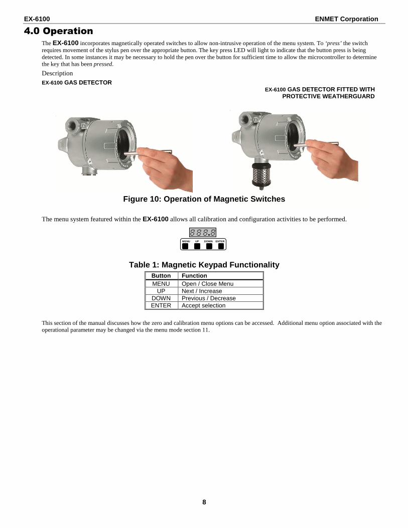
4.0 Operation The EX-6100 incorporates magnetically operated switches to allow non-intrusive operation of the menu system. To ‘press’ the switch requires movement of the stylus pen over the appropriate button. The key press LED will light to indicate that the button press is being detected. In some instances it may be necessary to hold the pen over the button for sufficient time to allow the microcontroller to determine the key that has been pressed.
Description EX-6100 GAS DETECTOR
EX-6100 GAS DETECTOR FITTED WITH PROTECTIVE WEATHERGUARD
Figure 10: Operation of Magnetic Switches
The menu system featured within the EX-6100 allows all calibration and configuration activities to be performed.
Table 1: Magnetic Keypad Functionality Button Function MENU Open / Close Menu
UP Next / Increase DOWN Previous / Decrease ENTER Accept selection
This section of the manual discusses how the zero and calibration menu options can be accessed. Additional menu option associated with the operational parameter may be changed via the menu mode section 11.
MENU UP DOWN ENTER
EX-6100 ENMET Corporation
9
5.0 Calibration
5.1 Sensor Calibration This feature allows the sensor to be calibrated. Ensure that the correct sensor type is selected in the configuration prior to calibration. Refer to section for details of the menu system operation.
5.1.1 Sensor Zero Tap the magnet over the menu switch, the display will change to Pass wait approximately 10 seconds and the display will show E 1.
Tap the magnet over the enter switch the display will flash E: 1 and 0
� If the zero is accepted the display will show ---- Tap the magnet over the menu switch to exit.
� If the zero calibration was not within acceptable range the display will show F2. A recalibration is required; you may need a cylinder of 20.9 air.
5.1.2 Sensor Span Tap the magnet over the menu switch, the display will change to Pass, wait approximately 10 seconds and the display will show E 1.
Tap the magnet over the up switch, the display will change to E 2.
Tap the magnet over the enter switch the display will flash E: 2 and XX (XX = the calibration gas level).
If the calibration gas you have does not match the displayed value, place the magnet over the up or down switch to adjust the value.
Tap the magnet over the enter switch, the display will flash E: 2
Apply the calibration gas.
The display will flash E: 2 and a number (sensor response to gas) when the number stops changing place the magnet over the up or down switch, the display will lock at the stable reading, example 49 or 53.
Place the magnet over the enter switch. The display will show ---- if the calibration was successful.
Tap the menu switch to exit and remove the calibration gas.
Caution: Be sure that the calibration gas you use matches the type and concentration of calibration gas display on the EX-6100 See Accessories Section 10 for ENMET Gas Cylinder part numbers.
Contact ENMET Corporation if there are any questions.
1 2 3 4
MENU UP DOWN ENTER
EX-6100 ENMET Corporation
10
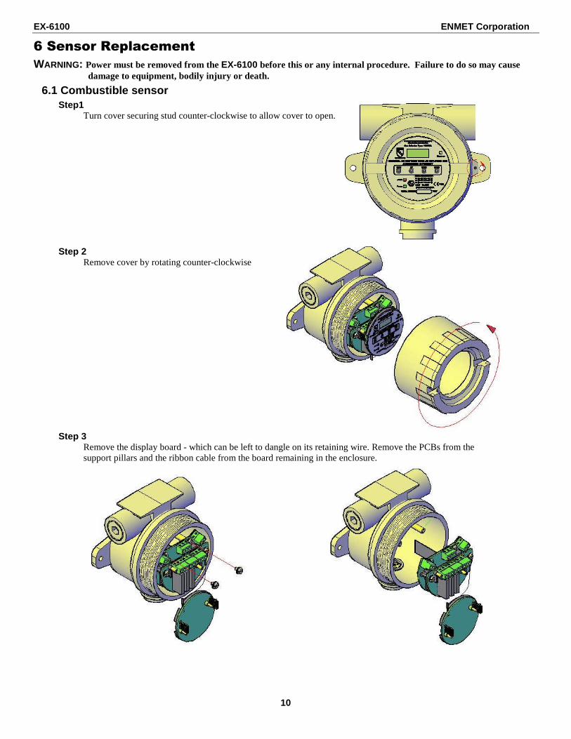
6 Sensor Replacement WARNING: Power must be removed from the EX-6100 before this or any internal procedure. Failure to do so may cause
damage to equipment, bodily injury or death.
6.1 Combustible sensor Step1
Turn cover securing stud counter-clockwise to allow cover to open.
Step 2 Remove cover by rotating counter-clockwise
Step 3 Remove the display board - which can be left to dangle on its retaining wire. Remove the PCBs from the support pillars and the ribbon cable from the board remaining in the enclosure.
EX-6100 ENMET Corporation
11
Step 4 Remove the sensor board from the rear of the sensor – do not disconnect the wires from the main board.
Step 5 Remove sensor insert using maintenance tool or slip joint pliers.
Step 6 Mark the sensor pin position & undo the snap ring that retains the sensor in its housing.
Step 7 Replace the sensor taking note of the pin marking in step 6.
EX-6100 ENMET Corporation
12
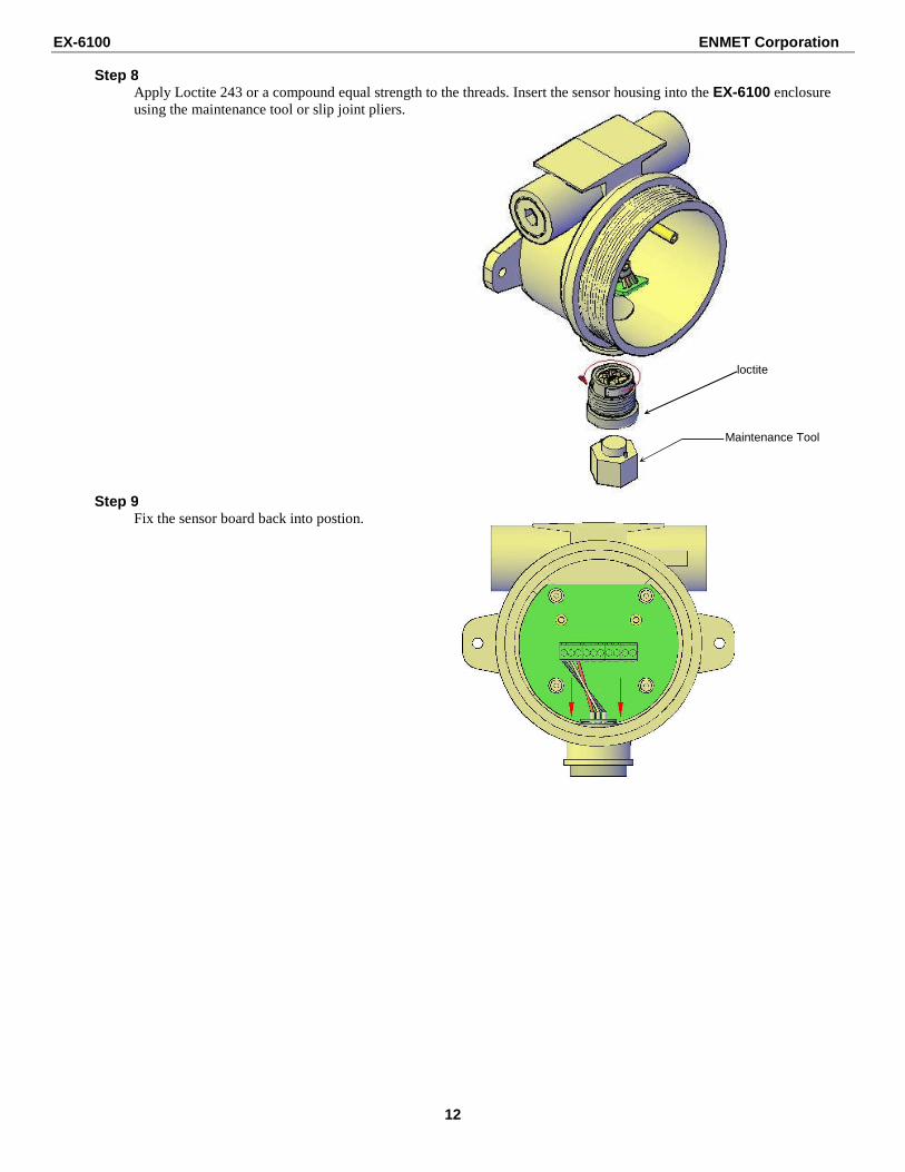
Step 8
Apply Loctite 243 or a compound equal strength to the threads. Insert the sensor housing into the EX-6100 enclosure using the maintenance tool or slip joint pliers.
Step 9 Fix the sensor board back into postion.
loctite
Maintenance Tool
EX-6100 ENMET Corporation
13
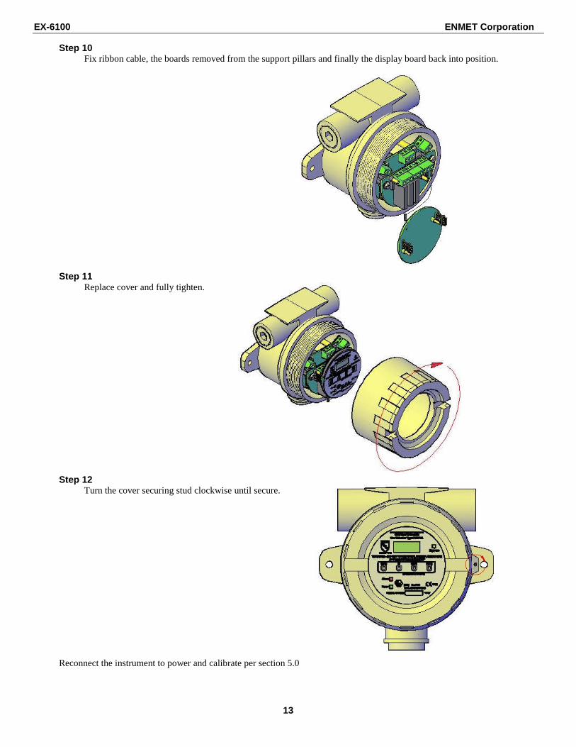
Step 10
Fix ribbon cable, the boards removed from the support pillars and finally the display board back into position.
Step 11 Replace cover and fully tighten.
Step 12 Turn the cover securing stud clockwise until secure.
Reconnect the instrument to power and calibrate per section 5.0
EX-6100 ENMET Corporation
14
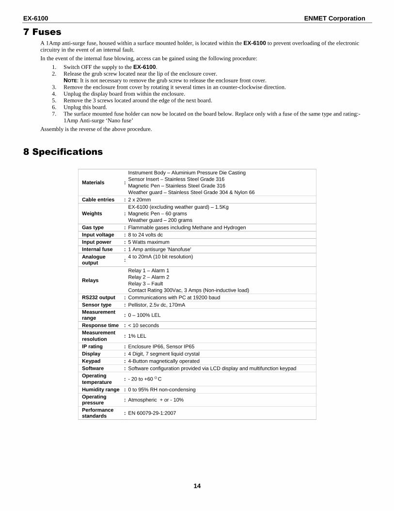
7 Fuses A 1Amp anti-surge fuse, housed within a surface mounted holder, is located within the EX-6100 to prevent overloading of the electronic circuitry in the event of an internal fault.
In the event of the internal fuse blowing, access can be gained using the following procedure:
1. Switch OFF the supply to the EX-6100. 2. Release the grub screw located near the lip of the enclosure cover.
NOTE: It is not necessary to remove the grub screw to release the enclosure front cover. 3. Remove the enclosure front cover by rotating it several times in an counter-clockwise direction. 4. Unplug the display board from within the enclosure. 5. Remove the 3 screws located around the edge of the next board. 6. Unplug this board. 7. The surface mounted fuse holder can now be located on the board below. Replace only with a fuse of the same type and rating:-
Gas type : Flammable gases including Methane and Hydrogen Input voltage : 8 to 24 volts dc Input power : 5 Watts maximum Internal fuse : 1 Amp antisurge 'Nanofuse' Analogue output :
RS232 output : Communications with PC at 19200 baud Sensor type : Pellistor, 2.5v dc, 170mA Measurement range : 0 – 100% LEL
Response time : < 10 seconds Measurement resolution
: 1% LEL
IP rating : Enclosure IP66, Sensor IP65 Display : 4 Digit, 7 segment liquid crystal Keypad : 4-Button magnetically operated Software : Software configuration provided via LCD display and multifunction keypad Operating temperature
: - 20 to +60 O C
Humidity range : 0 to 95% RH non-condensing Operating pressure : Atmospheric + or - 10%
Performance standards : EN 60079-29-1:2007
EX-6100 ENMET Corporation
15
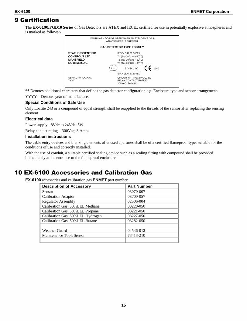
9 Certification The EX-6100/FGD10 Series of Gas Detectors are ATEX and IECEx certified for use in potentially explosive atmospheres and is marked as follows:-
** Denotes additional characters that define the gas detector configuration e.g. Enclosure type and sensor arrangement.
YYYY – Denotes year of manufacture.
Special Conditions of Safe Use Only Loctite 243 or a compound of equal strength shall be reapplied to the threads of the sensor after replacing the sensing element
Electrical data Power supply - 8Vdc to 24Vdc, 5W
Relay contact rating – 300Vac, 3 Amps
Installation instructions The cable entry devices and blanking elements of unused apertures shall be of a certified flameproof type, suitable for the conditions of use and correctly installed.
With the use of conduit, a suitable certified sealing device such as a sealing fitting with compound shall be provided immediately at the entrance to the flameproof enclosure.
10 EX-6100 Accessories and Calibration Gas EX-6100 accessories and calibration gas ENMET part number
11 Menu Mode The EX-6100 uses a password system to restrict the end user from carrying out certain changes that may compromise the use of the equipment. Menu Mode should only be entered by qualified personal.
To enter the menu mode Sequence Tap: Menu, Up, Down, Enter, Up, Enter, Up, Menu
If no inputs (taps) the EX-6100 returns to operational mode.
Several calibration modes exist in the EX-6100 and these are accessible via the instruments simple menu system. To select a calibration mode follow this procedure:
• Press the MENU button, E: 1 appears on the display. • Press UP or DOWN until the required menu option is displayed. • Press ENTER to select the calibration mode. • To exit the menu press MENU.
While the instrument is in menu mode – any data displayed on the screen will alternate between the cal number and the reading. The following features are available via the ‘EX-6100’ menu system:
Table 3: EX-6100 Menu Options Menu Option Section E : 1 – Sensor Zero 11.2.1 E : 2 – Sensor Span 11.2.2 E : 3 – Sensor FSD 11.2.3 E : 4 – Output Zero (4mA) 11.2.4 E : 5 – Output Span (20mA) 11.2.5 E : 6 – Decimal Places 11.2.6 E : 7 – Firmware Version 11.2.7 E : 8 – Restore 11.2.8 E : 9 – Engineer Diagnostics 11.2.9
� E : 12 – Cross Reference 11.2.10 E : 13 – Relay 1 11.2.11 E : 14 – Relay 2 11.2.12 E : 15 – Alarm Level 1 11.2.13 E : 16 – Alarm Level 2 11.2.14 E : 19 – Positive Zero Suppression 11.2.15 E : 20 – Negative Zero Suppression 11.2.16 E : 27 – Hysteresis 11.2.17
� E : 28 – Firmware Update 11.2.18 E : 29 – Relay 3 11.2.19 E : 30 – Password 11.2.20 E : 31 – Warm-Up Timer 11.2.21
� Contact ENMET Corporation before entering this menu option.
� Do Not enter this menu option.
11.2.1 E : 1 – Sensor Zero Refer to section 5.1.1 for sensor calibration details.
11.2.2 E : 2 – Sensor Span Refer to section 5.1.2 for sensor calibration details.
11.2.3 E : 3 – Sensor FSD This menu option allows the full-scale gas level to be selected.
From the menu system select menu option: E: 3 and press ENTER.
• Using the INCREASE and DECREASE buttons; adjust the FSD to the required level. • Press ENTER, ‘- - - - ‘will be displayed to indicate that the new setting has been accepted.
Note: Pressing MENU instead of ENTER will exit the menu without changing the FSD. • Press MENU to close the menu system.
11.2.4 E : 4 – Output Zero (4mA) Refer to section Appendix A for output calibration details.
11.2.5 E : 5 – Output Span (20mA) Refer to section Appendix A for output calibration details.
EX-6100 ENMET Corporation
17
11.2.6 E : 6 – Decimal Places The number of decimal places that are used to display the detected gas levels can be changed via this menu option.
• From the menu system select menu option: E: 6 and press ENTER. • Using the NEXT and PREVIOUS buttons, select the required number of decimal places. • Press ENTER.
NOTE: Pressing MENU instead of ENTER will exit the menu without changing the number of decimal places to which the gas level will be displayed.
• Press MENU to close the menu system.
Note that when the sensor type is first selected, the optimum number of decimal places for a given sensor type and range is automatically selected. Increasing the number of decimal places to which detected gas levels are displayed does not increase the sensitivity or accuracy of the instrument and in some cases may degrade the instruments perceived stability.
11.2.7 E : 7 – Firmware Version The Firmware version is displayed in the form X.Xyy, where X is numerical and y is a letter.
• Press MENU to close the menu system.
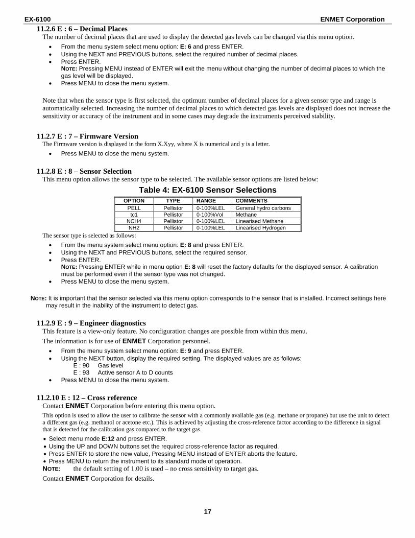
11.2.8 E : 8 – Sensor Selection This menu option allows the sensor type to be selected. The available sensor options are listed below:
Table 4: EX-6100 Sensor Selections OPTION TYPE RANGE COMMENTS
PELL Pellistor 0-100%LEL General hydro carbons tc1 Pellistor 0-100%Vol Methane
• From the menu system select menu option: E: 8 and press ENTER. • Using the NEXT and PREVIOUS buttons, select the required sensor. • Press ENTER.
NOTE: Pressing ENTER while in menu option E: 8 will reset the factory defaults for the displayed sensor. A calibration must be performed even if the sensor type was not changed.
• Press MENU to close the menu system.
NOTE: It is important that the sensor selected via this menu option corresponds to the sensor that is installed. Incorrect settings here may result in the inability of the instrument to detect gas.
11.2.9 E : 9 – Engineer diagnostics This feature is a view-only feature. No configuration changes are possible from within this menu.
The information is for use of ENMET Corporation personnel.
• From the menu system select menu option: E: 9 and press ENTER. • Using the NEXT button, display the required setting. The displayed values are as follows:
E : 90 Gas level E : 93 Active sensor A to D counts
• Press MENU to close the menu system.
11.2.10 E : 12 – Cross reference Contact ENMET Corporation before entering this menu option. This option is used to allow the user to calibrate the sensor with a commonly available gas (e.g. methane or propane) but use the unit to detect a different gas (e.g. methanol or acetone etc.). This is achieved by adjusting the cross-reference factor according to the difference in signal that is detected for the calibration gas compared to the target gas.
• Select menu mode E:12 and press ENTER. • Using the UP and DOWN buttons set the required cross-reference factor as required. • Press ENTER to store the new value, Pressing MENU instead of ENTER aborts the feature. • Press MENU to return the instrument to its standard mode of operation. NOTE: the default setting of 1.00 is used – no cross sensitivity to target gas.
Contact ENMET Corporation for details.
EX-6100 ENMET Corporation
18
11.2.11 E : 13 – Relay 1 The unit is fitted with a relay that is operated in conjunction with the alarm level. The user can select if the relay is normally Energized, E’ or normally de-energized, ‘d’ when the unit is not in an alarm condition.
• From the menu system select menu option: E: 13 and press ENTER. • The display will show the following:
• The mode of operation can be changed by pressing the UP button. • Press ENTER to accept the new relay mode of operation.
NOTE: Pressing MENU instead of ENTER leaves the unit without change. • Press MENU to return the instrument to its standard mode of operation.
11.2.12 E : 14 – Relay 2 The unit is fitted with a relay that is operated in conjunction with the alarm level. The user can select if the relay is normally Energized, ‘E’ or normally de-energized, ‘d’ when the unit is not in an alarm condition.
• From the menu system select menu option: E: 14 and press ENTER. • The display will show the following:
• The mode of operation can be changed by pressing the UP button. • Press ENTER to accept the new relay mode of operation.
NOTE: Pressing MENU instead of ENTER leaves the unit without change. • Press MENU to return the instrument to its standard mode of operation.
11.2.13 E : 15 – Alarm Level 1 The gas level that will cause Relay 1 to change state is set via this menu option.
• From the menu system select menu option: E: 15 and press ENTER. • Using the UP and DOWN buttons, adjust the displayed reading so that it matches the desired alarm set point. • Press ENTER to accept the new alarm level.
NOTE: Pressing MENU instead of ENTER aborts the feature. • Press MENU to return the instrument to its standard mode of operation.
11.2.14 E : 16 – Alarm Level 2 The gas level that will cause Relay 2 to change state is set via this menu option.
• From the menu system select menu option: E: 16 and press ENTER. • Using the UP and DOWN buttons, adjust the displayed reading so that it matches the desired alarm set point. • Press ENTER to accept the new alarm level.
NOTE: Pressing MENU instead of ENTER aborts the feature. • Press MENU to return the instrument to its standard mode of operation.
11.2.15 E : 19 – Positive Zero Suppression This option is used to allow the user to suppress small amounts of positive sensor zero drift. The setting can be set between 0 and 10% of the sensor range as set by the FSD value.
• Press MENU to open the menu system. • Using the NEXT and PREVIOUS buttons, select menu option: E:19 • Press ENTER. • Using the INCREASE and DECREASE buttons, set the required zero suppression value. • Press ENTER to store the new value.
Note: Pressing the MENU button rather than the ENTER button exits without any change. • Press MENU to close the menu system.
EX-6100 ENMET Corporation
19
11.2.16 E : 20 – Negative Zero Suppression This option is used to allow the user to suppress small amounts of negative sensor zero drift. The setting can be set between 0 and 10% of the sensor range as set by the FSD value.
• Press MENU to open the menu system. • Using the NEXT and PREVIOUS buttons, select menu option: E:20 • Press ENTER. • Using the INCREASE and DECREASE buttons, set the required zero suppression value. • Press ENTER to store the new value.
Note: Pressing the MENU button rather than the ENTER button exits without any change. • Press MENU to close the menu system.
11.2.17 E : 27 – Hysteresis This option sets the alarm hysteresis. The relays will chatter if this level is set to 100.
95% is the usual setting for pellistor sensors.
11.2.18 E : 28 – Firmware update Do Not Enter this Menu
11.2.19 E : 29 – Relay 3 The unit is fitted with a relay that is operated in conjunction with a fault condition. The user can select if the relay is normally Energized, ‘E’ or normally de-energized, ‘d’ when the unit is not in a fault condition.
• From the menu system select menu option: E: 29 and press ENTER. • The display will show the following:
• The mode of operation can be changed by pressing the UP button. • Press ENTER to accept the new relay mode of operation.
NOTE: Pressing MENU instead of ENTER leaves the unit without change. • Press MENU to return the instrument to its standard mode of operation.
11.2.20 E : 30 – Password Use this menu option to enable / disable the password feature.
Place the EX-6100 in the password menu as follows:
• Press the MENU to open the menu system. • Using the NEXT and PREVIOUS buttons, select menu option: E:30 • Press ENTER. • The display shows either On or OFF • Press the UP button to select the desired setting. • Press ENTER to accept the setting.
NOTE: Pressing MENU instead of ENTER leaves the unit without change. • Press MENU to return the instrument to its standard mode of operation.
Note: If the password is in operation then the user will be prompted with PASS when ever the menu key is pressed. Pressing the MENU key again will result in the restricted user access, i.e. only the zero and span options will be available. Entering the correct password will give access to the full menu facility.
11.2.21 E : 31 – Warm-up timer The sensor goes through a stabilization period when power is first applied. This option allows the user to adjust the time that is applied before readings are displayed / transmitted.
• From the menu system select menu option: E: 31 and press ENTER. • Using the INCREASE and DECREASE buttons, set the required warm-up time. • Press ENTER to store the new value.
Note: Pressing the MENU button rather than the ENTER button exits without any change.
Normally warm time is 45 seconds.
EX-6100 ENMET Corporation
20
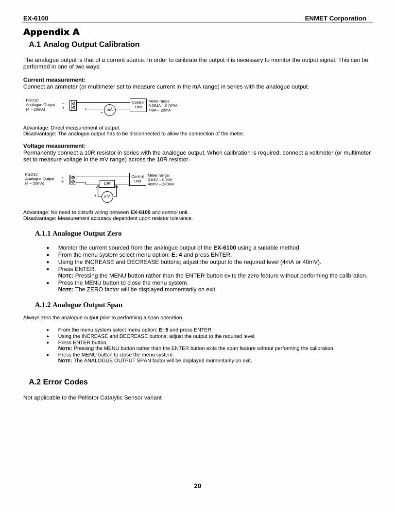
Appendix A A.1 Analog Output Calibration
The analogue output is that of a current source. In order to calibrate the output it is necessary to monitor the output signal. This can be performed in one of two ways: Current measurement: Connect an ammeter (or multimeter set to measure current in the mA range) in series with the analogue output. Advantage: Direct measurement of output. Disadvantage: The analogue output has to be disconnected to allow the connection of the meter. Voltage measurement: Permanently connect a 10R resistor in series with the analogue output. When calibration is required, connect a voltmeter (or multimeter set to measure voltage in the mV range) across the 10R resistor.
Advantage: No need to disturb wiring between EX-6100 and control unit. Disadvantage: Measurement accuracy dependent upon resistor tolerance.
A.1.1 Analogue Output Zero
• Monitor the current sourced from the analogue output of the EX-6100 using a suitable method. • From the menu system select menu option: E: 4 and press ENTER. • Using the INCREASE and DECREASE buttons; adjust the output to the required level (4mA or 40mV). • Press ENTER.
NOTE: Pressing the MENU button rather than the ENTER button exits the zero feature without performing the calibration. • Press the MENU button to close the menu system.
NOTE: The ZERO factor will be displayed momentarily on exit.
A.1.2 Analogue Output Span Always zero the analogue output prior to performing a span operation.
• From the menu system select menu option: E: 5 and press ENTER. • Using the INCREASE and DECREASE buttons; adjust the output to the required level. • Press ENTER button.
NOTE: Pressing the MENU button rather than the ENTER button exits the span feature without performing the calibration. • Press the MENU button to close the menu system.
NOTE: The ANALOGUE OUTPUT SPAN factor will be displayed momentarily on exit.
A.2 Error Codes Not applicable to the Pellistor Catalytic Sensor variant
– +
FGD10 Analogue Output (4 – 20mA)
Control Unit
mA +
Meter range: 0.004A – 0.020A 4mA – 20mA
– +
FGD10 Analogue Output (4 – 20mA)
Control Unit
10R
mV +
Meter range: 0.04V – 0.20V 40mV – 200mV
EX-6100 ENMET Corporation
21
A.3 Communications Protocol The communications protocol used by the EX-6100 is used for communications between devices connected via an RS232 connection at 19200 baud, 8 data bits 1 stop bit, no parity. This point-to-point, P2P, protocol is a frame-based protocol.
A.3.1 Hardware connections PC 9-way ‘D’ connector EX-6100 connection
2 Tx 3 Rx 5 0V
PC 25-way ‘D’ connector EX-6100 connection
3 Tx 2 Rx 7 0V
A.3.2 Control Byte Constants The following control byte constants are used in the P2P protocol.
Read, RD = 0x13 (00010011) Data Link Escape, DLE = 0x10 (00010000)
A.4 Frame Structure The start of a frame is indicated by a DLE byte followed by the type of frame to follow (RD, WR, ACK, NAK, DAT). The end of frame is indicated by a DLE byte followed by an EOF byte.
Note: Each of the constants has bit 4 set and so is slip-resistant (i.e. if shifted this bit will be out of position). The values have a Hamming Distance of 2 (each code is at least 2 bits different from every other code).
Any DLE bytes that occur between a frame’s start and end are prefixed with another DLE (byte-stuffing).
Following the EOF is a 16-bit checksum of the entire frame, each byte is added to produce the checksum.
A.4.1 Variables Each piece of accessible data on a device is referred to as a Variable. Each variable is referenced by a Variable ID. A variable ID may be any number of bytes long.
The available Variables and their corresponding Variable IDs depend on the type of device, but here are a few examples for the EX-6100:
General Configuration 0x00 Live Data 0x01 Zero Sensor 0x02 Span Sensor 0x03 Version Information 0x04 Firmware Update 0x05
The structure of the data returned in each variable usually depends both on the type of device and the version of firmware running on the device.
Refer to device documentation for more information.
EX-6100 ENMET Corporation
22
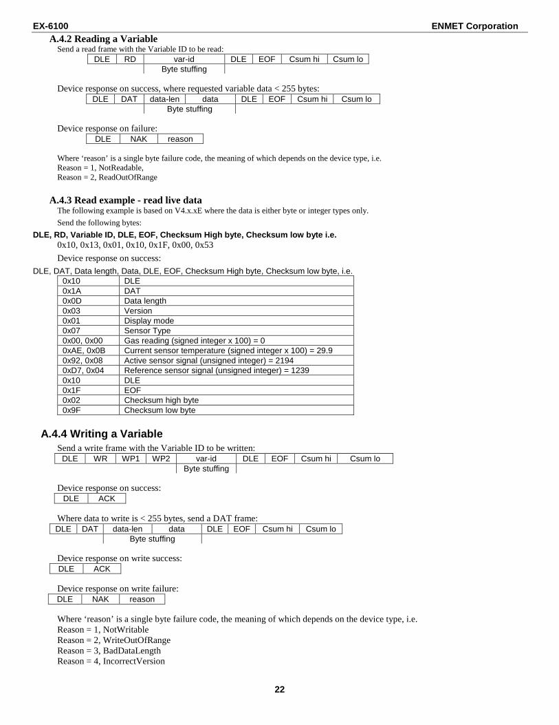
A.4.2 Reading a Variable Send a read frame with the Variable ID to be read:
DLE RD var-id DLE EOF Csum hi Csum lo Byte stuffing
Device response on success, where requested variable data < 255 bytes:
DLE DAT data-len data DLE EOF Csum hi Csum lo Byte stuffing
Device response on failure:
DLE NAK reason Where ‘reason’ is a single byte failure code, the meaning of which depends on the device type, i.e. Reason = 1, NotReadable, Reason = 2, ReadOutOfRange
A.4.3 Read example - read live data The following example is based on V4.x.xE where the data is either byte or integer types only. Send the following bytes:
DLE, RD, Variable ID, DLE, EOF, Checksum High byte, Checksum low byte i.e. 0x10, 0x13, 0x01, 0x10, 0x1F, 0x00, 0x53
Device response on success:
DLE, DAT, Data length, Data, DLE, EOF, Checksum High byte, Checksum low byte, i.e. 0x10 DLE 0x1A DAT 0x0D Data length 0x03 Version 0x01 Display mode 0x07 Sensor Type 0x00, 0x00 Gas reading (signed integer x 100) = 0 0xAE, 0x0B Current sensor temperature (signed integer x 100) = 29.9 0x92, 0x08 Active sensor signal (unsigned integer) = 2194 0xD7, 0x04 Reference sensor signal (unsigned integer) = 1239 0x10 DLE 0x1F EOF 0x02 Checksum high byte 0x9F Checksum low byte
A.4.4 Writing a Variable Send a write frame with the Variable ID to be written:
DLE WR WP1 WP2 var-id DLE EOF Csum hi Csum lo Byte stuffing
Device response on success:
DLE ACK Where data to write is < 255 bytes, send a DAT frame: DLE DAT data-len data DLE EOF Csum hi Csum lo Byte stuffing Device response on write success: DLE ACK Device response on write failure: DLE NAK reason Where ‘reason’ is a single byte failure code, the meaning of which depends on the device type, i.e. Reason = 1, NotWritable Reason = 2, WriteOutOfRange Reason = 3, BadDataLength Reason = 4, IncorrectVersion
EX-6100 ENMET Corporation
23
WARRANTY
ENMET warrants new instruments to be free from defects in workmanship and material under normal use for a period of one year from date of shipment from ENMET. The warranty covers both parts and labor excluding instrument calibration and expendable parts such as calibration gas, filters, batteries, etc... Equipment believed to be defective should be returned to ENMET within the warranty period (transportation prepaid) for inspection. If the evaluation by ENMET confirms that the product is defective, it will be repaired or replaced at no charge, within the stated limitations, and returned prepaid to any location in the United States by the most economical means, e.g. Surface UPS/FedEx Ground. If an expedient means of transportation is requested during the warranty period, the customer is responsible for the difference between the most economical means and the expedient mode. ENMET shall not be liable for any loss or damage caused by the improper use of the product. The purchaser indemnifies and saves harmless the company with respect to any loss or damages that may arise through the use by the purchaser or others of this equipment.
This warranty is expressly given in lieu of all other warranties, either expressed or implied, including that of merchantability, and all other obligations or liabilities of ENMET which may arise in connection with this equipment. ENMET neither assumes nor authorizes any representative or other person to assume for it any obligation or liability other than that which is set forth herein.
NOTE: When returning an instrument to the factory for service:
� Be sure to include paperwork. � A purchase order, return address and telephone number will assist in the expedient repair and return of your unit. � Include any specific instructions. � For warranty service, include date of purchase � If you require an estimate, please contact ENMET Corporation.
There are Return for Repair Instructions and Form on the last pages of this manual. This Form can be copied or used as needed.
Manual Part Number 80003-122
November 2012 MCN-14-001, 01/22/14
Notes:
PO Box 979 680 Fairfield Court Ann Arbor, Michigan 48106-0979 734.761.1270 Fax 734.761.3220
Returning an Instrument for Repair
ENMET instruments may be returned to the factory or any one of our Field Service Centers for regular repair service or calibration. The ENMET Repair Department and Field Service Centers also perform warranty service work.
When returning an instrument to the factory or service center for service, paperwork must be included which contains the following information:
� A purchase order number or reference number.
� A contact name with return address, telephone and fax numbers
� Specific instructions regarding desired service or description of the problems being encountered.
� Date of original purchase and copy of packing slip or invoice for warranty consideration.
� If a price estimate is required, please note it accordingly and be sure to include a fax number.
Providing the above information assists in the expedient repair and return of your unit.
Failure to provide this information can result in p rocessing delays.
ENMET charges a one hour minimum billing for all approved repairs with additional time billed to the closest tenth of an hour. All instruments sent to ENMET are subject to a minimum evaluation fee, even if returned unrepaired. Unclaimed instruments that ENMET has received without appropriate paperwork or attempts to advise repair costs that have been unanswered, after a period of 60 days, may be disposed of or returned unrepaired COD with the evaluation fee. Service centers may have different rates or terms. Be sure to contact them for this information.
Repaired instruments are returned by UPS/FedEx Grou nd and are not insured unless otherwise specified. If expedited shipping methods or insura nce is required, it must be stated in your paperwor k.
Note: Warranty of customer installed components.
If a component is purchased and installed in the field, and fails within the warranty term, it can be returned to ENMET and will be replaced, free of charge, per ENMET’s returned goods procedure.
If the entire instrument is returned to ENMET Corporation with the defective item installed, the item will be replaced at no cost, but the instrument will be subject to labor charges at half of the standard rate.
Repair Return Form
Mailing Address: ENMET Corporation PO Box 979 Ann Arbor, Michigan 48106 Phone Number: 734.761.1270 FAX Number: 734.761.3220
Shipping Address: ENMET Corporation Attn: Repair Department 680 Fairfield Court Ann Arbor, Michigan 48108
Your Mailing Address:
Your Shipping Address:
Contact Name: __________________________ Your Phone: _______________________
Your PO/Reference Number: _______________ Your FAX: _______________________