Table of Contents PILLAR GRIDDING.........................................................2 Important icons used in the process steps: ...................................................................................... 2 Exercise Overview:............................................................................................................................... 2 A) BEFORE PILLAR GRIDDING................................................3 Exercise Steps...................................................................................................................................... 3 B) CREATE A NEW 3D GRID.................................................3 Exercise Steps...................................................................................................................................... 3 C) CREATE A SIMPLE GRID BOUNDARY AND QUALITY CHECK YOUR FAULT MODEL.............4 Exercise Steps...................................................................................................................................... 4 D) CREATE A SEGMENT GRID BOUNDARY.........................................5 Exercise Steps...................................................................................................................................... 5 Comments............................................................................................................................................ 6 E) INSERT DIRECTIONS AND TRENDS...........................................6 General guidelines:............................................................................................................................. 7 Exercise Steps...................................................................................................................................... 7 Comments............................................................................................................................................ 9 F) PILLAR GRIDDING......................................................9 G) QC OF SKELETON GRID.................................................10 Exercise step...................................................................................................................................... 10 Comments.......................................................................................................................................... 10 H) OPTIONAL: SPECIFY NUMBER OF CELLS.....................................11 I) OPTIONAL: DEFINING SEGMENTS USING TRENDS................................12 J) OPTIONAL: SET FAULT UNDEFINED.........................................14 K) Optional: Set fault not part of segment boundary.................14 The Pillar Gridding process is the generation of a spatial framework. In this exercise you will generate skeleton grids based on the Key Pillars as defined in the previous exercise. The Key Pillars will be converted into fault surfaces that are defined by Pillars. Pillars will also be inserted in between the faults and as such, define the grid cell size in the I and the J directions. You will learn how the skeleton grids are generated and how it is possible to apply trends and directions to improve the quality of the grid. The grid cell size (increment) in the I and the J directions will be specified. The final step will be to perform a quality control check on the generated skeleton grids by playing through it in the I and the J directions. The skeleton grids will be divided into segments separated by Petrel Introduction Course P2002 (v.7/02) Page 1 Pillar Gridding
Transcript
Table of ContentsPILLAR GRIDDING.......................................................................................................................2
Important icons used in the process steps:.............................................................................2Exercise Overview:................................................................................................................2
A) BEFORE PILLAR GRIDDING....................................................................................................3Exercise Steps.......................................................................................................................3
B) CREATE A NEW 3D GRID.......................................................................................................3Exercise Steps.......................................................................................................................3
C) CREATE A SIMPLE GRID BOUNDARY AND QUALITY CHECK YOUR FAULT MODEL.............................4Exercise Steps.......................................................................................................................4
D) CREATE A SEGMENT GRID BOUNDARY....................................................................................5Exercise Steps.......................................................................................................................5Comments............................................................................................................................. 6
E) INSERT DIRECTIONS AND TRENDS...........................................................................................6General guidelines:................................................................................................................7Exercise Steps.......................................................................................................................7Comments............................................................................................................................. 9
F) PILLAR GRIDDING.................................................................................................................9G) QC OF SKELETON GRID......................................................................................................10
H) OPTIONAL: SPECIFY NUMBER OF CELLS................................................................................11I) OPTIONAL: DEFINING SEGMENTS USING TRENDS....................................................................12J) OPTIONAL: SET FAULT UNDEFINED.......................................................................................14K) Optional: Set fault not part of segment boundary..............................................................14
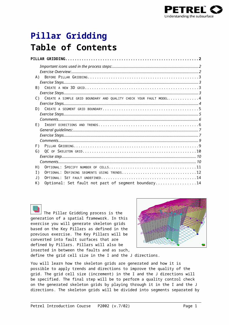
The Pillar Gridding process is the generation of a spatial framework. In this exercise you will generate skeleton grids based on the Key Pillars as defined in the previous exercise. The Key Pillars will be converted into fault surfaces that are defined by Pillars. Pillars will also be inserted in between the faults and as such, define the grid cell size in the I and the J directions.
You will learn how the skeleton grids are generated and how it is possible to apply trends and directions to improve the quality of the grid. The grid cell size (increment) in the I and the J directions will be specified. The final step will be to perform a quality control check on the generated skeleton grids by playing through it in the I and the J directions. The skeleton grids will be divided into segments separated by faults and boundaries. Each segment will have a specific number of cells, which can be changed to make the grid density higher or lower for specific segments.
The generated skeleton grids, also called pillar grid, defines the spatial framework into which the horizons will be inserted later. This means that the pillars are not associated with Z-values. The three skeleton grids that are created do not represent surfaces. Rather, they represent the position of the pillars at the top, middle and base levels.
In the next process (the Make Horizon process) will the horizons be inserted and connected to the pillars, and cells in the z-direction will be defined. A 3D grid will first be generated after this process has been completed.
The goal of the Pillar Gridding process is to create evenly distributed rectangular shaped grid cells.
Petrel Introduction Course P2002 (v.7/02) Page 1
Pillar Gridding
Important icons used in the process steps:
Create boundary Set part of grid boundary
Create boundary segment Set part of segment boundary
Set I-direction Set no boundary
Set J-direction Set no fault
Set arbitrary direction New I-trend
New J-trend
Exercise Overview:A) Before Pillar Gridding
B) Create a new skeleton grid
C) Create a simple grid boundary and quality check your fault model
D) Create a segment boundary
E) Insert directions and trends
F) Pillar Gridding
G) QC of Skeleton grid
H) Optional Exercises (Specify number of cells, Defining segments using trends, Set fault undefined, Set fault not part of segment boundary)
A) Before Pillar GriddingSince Pillar Gridding uses the Key Pillars that define the faults and their intersections to guide the building of the final pillars, the Key Pillars must be properly constructed. Before starting Pillar Gridding a series of checks need to be performed to ensure that the fault modeling process is complete. Once these checks have been performed then Pillar Gridding can be initialized and the skeleton grids created.
Exercise StepsIn the 3D window display all the faults in the fault model.1. Ensure that all faults intersecting are connected properly. Laterally connected faults should
have a shared (gray) Key Pillar.2. Check and see that a fault is not represented twice in the model.3. The transition between all the neighboring pillars should be smooth.4. Faults represented by Key Pillars should not cross each other. Display in the faults in the 3D
window with the Toggle fill . Check all faults and ensure that the triangulated surface between the different Key Pillars is not crossing.
Petrel Introduction Course P2002 (v.7/02) Page 2
B) Create a new 3D gridPillar gridding creates the first component (pillars) of a 3D grid. Because of this the process must either create a new 3D Grid or write over the top of an existing one. When updating a model you should overwrite an existing 3D Grid because the settings will already be set from previous executions and make the update easier. The best way to do this is to copy the 3D Grid and overwrite the copied version.
Some key settings such as name of the 3D grid and the grid increment are set when initializing the Pillar Gridding process, although they can be altered at any time.
Exercise Steps1. Start the process of creating a new 3D Grid. Note that when you double clicked on Pillar
Gridding in the Process Diagram, a 2D window opened with your fault model displayed. The line is the projection line between the Key Pillars mid-points you defined in the previous exercise. The dots are the mid-point on the Key Pillar it self.
2. Enter a name for the 3D grid (3D Grid) and specify the I and J increment (100).3. Move the Pillar Gridding window out of the way but leave it up, as it will be used repeatedly in
the following exercises.
C) Create a simple grid boundary and quality check your fault model
The boundary marks the lateral extent of the 3D grid. It can be defined interactively in a number of ways. The boundary may completely enclose the faults or it may cut across faults. Alternatively faults can form part of the grid boundary. The 3D Grid is only defined inside the boundary. Therefore no volumes, structural horizons, or attribute cells will be calculated or exist outside the boundary.
To completely enclose all faults in the 3D grid the tool for Create boundary can be used. This option is used for digitizing a boundary in the 2D window.
Petrel Introduction Course P2002 (v.7/02) Page 3
Exercise Steps1. Display one of the time surfaces in the input tab of Petrel Explorer in the 2D window. This will
be used as a guide when digitizing the boundary.
2. Start creating a boundary around the area of interest by using the icon Create boundary and click with the left mouse button to draw a boundary. Double click on the left mouse button to close the boundary.
3. Build a 2D grid (QC check) by double clicking on the Pillar Gridding process in the Process Diagram and pressing Apply. If the boundary is not closed, then close it. Key Pillars that are crossing each other will be marked with yellow dots. If this is so then go to the Window menu and Tile Vertical the 3D window with the fault model displayed and the 2Dwindow with the Pillar grid displayed. The problem pillars will be displayed in the 3D window as well, activate the Fault Modeling process and fix the problem by editing the Key Pillars. Run the Pillar Gridding process over again.
D) Create a segment grid boundary
Exercise Steps1. Display one of the time surfaces in the input tab of Petrel Explorer in the 2D window. This will
be used as a guide when digitizing the boundary.2. Start by making faults, on the left side of the area, part of the boundary. Use the Set
Select/Pick mode to mark a fault. Note that when clicking on the line connecting the shape points on the fault (the dots) the whole fault becomes yellow. This means that the fault is selected and you can give it a purpose. Alternatively you can press one shape point (start point) hold the Shift key and press the end shape point (the start and end shape point turn yellow).
3. Click on the Set part of grid boundary icon. Note that the fault or the part of fault will be marked with a double blue line, as shown in the figure below.
4. Continue the boundary from fault to fault (digitizing points in between) on the south, east, and north sides of the boundary.
Petrel Introduction Course P2002 (v.7/02) Page 4
5. Select the Create Boundary Segment icon. 6. Click on the point on a fault to start digitizing the boundary from.7. Digitizing the boundary between the faults so it matches the surface displayed. You can
digitize anyway you like but you can not cross faults.8. Click on a shape point on a fault to end the boundary.9. Continue to set the boundary for the rest of the area.10. Build a 2D grid (QC check) by pressing Apply. If the boundary is not closed, then close it. If
Key Pillars are crossing, then go back to the Fault Modeling process, change the view to 3D display and edit the Key Pillars so that they are no longer crossing. Press Apply over again.
CommentsIt is possible to move parts and delete parts of the digitized boundary. The Pillar Gridding process must be active in the Process Diagram (the name is bold in the Petrel Explorer) and the boundary is displayed in the 2D window.
Select the Select and Edit/Add points icon. Click on the point to be moved on one of the digitized lines and moving it to the desired position.
To create a new point click on the line between two points and move a little.
Points are deleted by selecting the Set select/pick mode icon. Click on the point to be deleted and press the Delete key. To delete several points hold the Shift key down and select points with the set select/pick mode. To delete a whole boundary click on the line between the digitized points, and press delete.
Faults have to be deleted and edited in the 3D window using the Fault Modeling process. But trends can be edited and deleted as described above.
It is possible to remove a fault from being part of the boundary
Select the Select and Edit/Add points icon. Click on the entire fault by clicking on the line between the shape points or select part of a fault clicking on a shape point (start point), holding the Shift key and pressing another shape point (end point).
Click on the Set Segment Boundary icon. The selected portion of the fault will turn from blue to white, indicating that it is no longer part of the boundary but still defines a segment boundary (fault is used as a boundary for cell construction).
E) Insert directions and trendsFault I- or J-directions are terms used by Petrel to identify faults that exert strong control when Pillar Gridding. Fault directions may be of three types: Arbitrary, I, and J. Arbitrary direction is the default setting for all faults. I direction (faults are colored green in the 2D window) is used for faults trending in one direction. J-direction (faults are colored red in the 2D window) is used for faults trending orthogonal to the I-direction. During Pillar Gridding faults designated as either I or J will have sides of the final cells oriented parallel to their fault surfaces and the surface will make up one side of adjacent cells. Arbitrary fault surfaces will also
Petrel Introduction Course P2002 (v.7/02) Page 5
make up one side of adjacent cells. However, the other side of the adjacent cells and the sides of other nearby cells will not be oriented parallel to these faults. This means that the geometric form of cells adjacent to arbitrary faults is very non-orthogonal and the form of cells adjacent to an I- or J-directed fault is close to orthogonal.
Trends are lines, created by you, that improve the quality of the grid. Trends act just like I- or J-directed faults during Pillar Gridding, implying that like trends and directions should be aligned parallel to each other (I || I, J || J, I _|_ J). A trend can be inserted to guide the gridding process. If you insert a green trend it must be parallel to the green directions, and a red trend must be parallel to the red directions.
General guidelines: Start simple, preferably with no directions, and insert directions only where necessary.
Red (or green) directions and trends should be parallel to each other.
Red directions should be perpendicular to sets of green directions and visa versa.
The space between like directed faults should be about the same along the length of the direction.
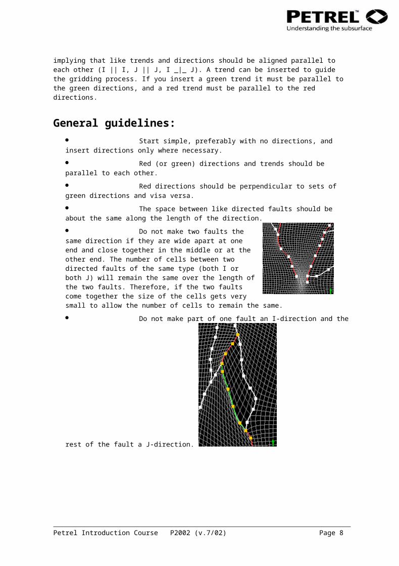
Do not make two faults the same direction if they are wide apart at one end and close together in the middle or at the other end. The number of cells between two directed faults of the same type (both I or both J) will remain the same over the length of the two faults. Therefore, if the two faults come together the size of the cells gets very small to allow the number of cells to remain the same.
Do not make part of one fault an I-direction and the rest of the fault a J-direction.
Petrel Introduction Course P2002 (v.7/02) Page 6
Do not put in to many similar directions too close together.
Exercise Steps1. Look for the overall fault pattern in the 2D window. In this case the major faults are oriented
North-South. Give the main fault(s) aligned North-South a red J direction. With the Select/Pick
mode icon select the line between the shape points to select the fault and press Set J-
direction icon.2. Give a perpendicular fault a green I direction, selecting the faults in the same manner as
above and pressing Set I-direction icon.3. Press Apply in the process window and observe the changes in the mid skeleton grid. Note
that the cells along the directed faults are aligned parallel to the fault whereas the cells along the arbitrary fault (white) are cut towards the fault.
4. Continue to set directions to all major faults in the project.
Petrel Introduction Course P2002 (v.7/02) Page 7
5. Insert a trend in the I direction (green) between two J directed faults (red), similar to the left
figure below.
6. Press Apply and observe how the cells are aligned along the trend line (right figure above).7. Make sure that the direction and trend alignment are ok by QC the mid-skeleton grid in the 2D
window. Add directions on faults and trends to refine the mid-skeleton grid.
Comments Note that the number of cells is constant between to faults defined with direction. This is illustrated on the figure above.
It is possible to move parts and delete parts of the digitized trend. The Pillar Gridding process must be active in the Process Diagram (the name is bold in the Petrel Explorer) and the trend is displayed in the 2D window.
Select the Select and Edit/Add points icon. Click on the point to be moved on one of the digitized lines and moving it to the desired position.
To create a new point click on the line between two points and move a little.
Points are deleted by selecting the Set select/pick mode icon. Click on the point to be deleted and press the Delete key. To delete several points hold the Shift key down and select points with the set select/pick mode. To delete a whole trend click on the
Petrel Introduction Course P2002 (v.7/02) Page 8
line between the digitized points, the trend should now be selected. Press delete. Alternatively open the trend folder under the fault model folder in Petrel Explorer, model tab. Find the trend to delete, highlight it and press delete.
F) Pillar GriddingAfter the Boundary has been defined and the 2D cell geometry tuned to the point of acceptability (trends and directions may be applied to help tuning the 2D cell geometry), the 3D grid can be constructed. The result of this construction is the Skeleton, which is a series of pillars, one for the corner of each cell. Top, middle and base skeleton grids are used to view these pillars easily in the X-Y dimensions. The pillars themselves are viewed in intersection to check their integrity.
Under the Pillar Geometry tab in the Pillar Gridding process window, toggle off ‘Curved’ for the ‘Non-Faulted Pillars’. This will create a simpler 3D Grid geometry with less chance for problems.
When the result is satisfying press OK to make the top and base skeleton grid. Say "Yes" to the window that pops up (asking if you want to build the top and base skeleton grids).
G) QC of Skeleton gridYou should always do a quality control check after the skeleton grid has been generated. The important steps during QC involve checking for crossing pillars. Crossing pillars will generate negative cell volumes. If you find crossing pillars, you must either do the Pillar Gridding over again and use directions and/or trends to avoid the crossing pillars, but most likely you will have to go back to the Fault Modeling process and adjust the Key Pillars.
The reason why the QC is important after the construction of the skeleton grids, even if the mid skeleton grid was fine during the Pillar Gridding process, is because Petrel only checks for crossing pillars for the mid skeleton when Pillar Gridding. When extrapolating the pillars to create the top and base skeleton, Petrel will not check for any crossing pillars.
Petrel Introduction Course P2002 (v.7/02) Page 9
Exercise step1. Activate the project in the Model tab of Petrel Explorer.2. Open the Skeleton folder in the newly created 3D grid.3. Perform a visual check of the grids individually in the 3D window, look for spikes and
irregularities. The comments below describe what to look for.4. Display the Key Pillars from the fault model to locate the problem.5. In the 3D window display a J-intersection from the “Intersections” folder. Click on the name to
make it active. 6. Double click on the intersection folder and toggle on show pillars in the style tab settings
window.
7. Use the player to move the intersection along the grid. Check the pillar geometries for crossing pillars.
8. Perform the necessary corrections on process the fault model to improve the skeleton grids
(you will have to run the Pillar Gridding again).
CommentsThings to look for:
Look for folded grid cells in the top, mid, and base skeleton grids. These may be more easily seen in 2D or section windows. In this situation grid cells have folded back over the top of others. A common cause of this is too much directional control of the cells. Consider setting some of the faults or trends to arbitrary directions.
Look for spikes in the top, mid, and base skeleton grids. These are caused by a variety of things including: short Key Pillars between longer ones, similarly directed faults that are not parallel and come close together, poorly placed trend lines, among others.
Petrel Introduction Course P2002 (v.7/02) Page 10
Look for crossing pillars in the intersection planes. In the data used for this exercise there should be no problem with crossing pillars in the skeleton. However, if the fault pattern is more complex, this is something to be aware of.
Tips: It is possible to tile the 3D and 2D window. Click on window in the Petrel main manual and select tile vertical from the appearing pull-down window. The windows in the project will be tiled to fill the screen. If the Fault Modeling process is active you can click on a Key Pillar in the 3D window and it will be highlighted in the 2D window and vise versa.
H) Optional: Specify number of cellsSometimes too few points are created in a certain part of the model. Often this is between two narrow faults where it is desired to have more cells when interpolating attributes. Additional cells give the attribute model more interpolation freedom. The same situation can occur between two closely spaced wells. Adding a trend between the two faults and specifying the number of cells does this.
Occasionally defining the number of cells in one area will rob cells from another area, creating a very poor geometric model. Therefore QC the mid skeleton before you create the top and base skeleton grids.
Petrel Introduction Course P2002 (v.7/02) Page 11
Exercise steps1. In the 2D window find an area where you have two faults with same direction next to each
other. If you don’t have this configuration on your faults then create it.2. Define a trend between the two faults, if you already have one, you can use that.
3. Define the number of cells that should exist along one of the defined trends using the tool . Make it significantly different from those currently existing along the trend.
4. Press Apply and observe how Petrel inserts the specific number of cells in the entire interval between the directed faults.
5. If the number of cells looks acceptable then leave it, if it looks like a problem then alter the number and re-Apply.
I) Optional: Defining segments using trendsBy default all faults in the model are set to segment divider. If the faults are connected properly an area limited by faults in all directions defines a segment. Hence, a fault block is referred to as a segment. The figure below shows a skeleton grid colored with a different color for each segment. Note how the segments are limited by connected faults and have a specified color.
This exercise will show how trends can be added to separate one the model areas from another. If, for example, the fluid contact is significantly different in parts of the model, care should be taken to define the segments. In each segment different input data can be used, hence also different fluid contacts. After creation, the trend is set to be part of a segment boundary.
Petrel Introduction Course P2002 (v.7/02) Page 12
The next exercise will focus on how faults and parts of faults can be set to undefined or not to be a segment divider.
Exercise steps1. In the Pillar Gridding process window, under the Settings tab, choose ‘Create new, named’
and give the grid a different name, for instance “3D grid making segments”.2. Find a fault that does not terminate against another fault. Digitize an appropriate trend using
the New J-trend or the New I-trend icon from the end point of the fault and attach it to the intersecting shape point on the other fault, illustrated in the figure below. This trend will now work as any other trend and guide the gridding process.
3. To make the trend a “segment divider”, click on the Set Part of Segment Boundary icon. After this feature is applied the trend will have a brighter color.
4. Display the skeleton grid colored with different colors for the segments. Open settings for the skeleton folder in the previous 3D grid, and check show solid as segments. Do the same for the “3D grid making segments”. Note the difference in the segments.
Make a trend not a segment boundary (turn it off)
1. Select the Set Select/Pick Mode icon. 2. Click on the trend line to have the segment boundary designation turned off.
3. Click on the Set No Boundary icon.
J)Optional: Set fault undefined If a fault or a part of a fault is set to be undefined and if it is given a direction the fault will be treated as a 3D trend in the gridding process and not incorporated as a fault in the generated 3D grid.
Exercise steps1. In the 3D window select the fault or part of the fault.
2. Click on the Set No Fault icon.3. The selected part of the fault will become dotted.
Petrel Introduction Course P2002 (v.7/02) Page 13
K) Optional: Set fault not part of segment boundary
If a fault is set to not be a segment boundary the selected fault or trend will not separate fault compartments and the trend will only operate as a trend, not work as a ”segment divider”.
Exercise steps1. In the 3D window select the fault/trend or part of the fault/trend
2. Click on the Set No Boundary icon.3. The selected part of the fault will become grey. If the fault already has a J-direction, it will
show as a solid line, with a dark red color. A green trend (I) will show as a dotted line with a dark