334
EX4300 Switch Hardware Guide Modified: 2017-10-18 Copyright © 2017, Juniper Networks, Inc.

EX4300 Switch Hardware Guide
Modified: 2017-10-18
Copyright © 2017, Juniper Networks, Inc.

Juniper Networks, Inc.1133 InnovationWaySunnyvale, California 94089USA408-745-2000www.juniper.net
Juniper Networks, the Juniper Networks logo, Juniper, and Junos are registered trademarks of Juniper Networks, Inc. and/or its affiliates inthe United States and other countries. All other trademarks may be property of their respective owners.
Juniper Networks assumes no responsibility for any inaccuracies in this document. Juniper Networks reserves the right to change, modify,transfer, or otherwise revise this publication without notice.
EX4300 Switch Hardware GuideCopyright © 2017 Juniper Networks, Inc. All rights reserved.
The information in this document is current as of the date on the title page.
YEAR 2000 NOTICE
Juniper Networks hardware and software products are Year 2000 compliant. Junos OS has no known time-related limitations through theyear 2038. However, the NTP application is known to have some difficulty in the year 2036.
ENDUSER LICENSE AGREEMENT
The Juniper Networks product that is the subject of this technical documentation consists of (or is intended for use with) Juniper Networkssoftware. Use of such software is subject to the terms and conditions of the End User License Agreement (“EULA”) posted athttp://www.juniper.net/support/eula/. By downloading, installing or using such software, you agree to the terms and conditions of thatEULA.
Copyright © 2017, Juniper Networks, Inc.ii
Table of Contents
About the Documentation . . . . . . . . . . . . . . . . . . . . . . . . . . . . . . . . . . . . . . . . . . . xvii
Documentation and Release Notes . . . . . . . . . . . . . . . . . . . . . . . . . . . . . . . . xvii
Supported Platforms . . . . . . . . . . . . . . . . . . . . . . . . . . . . . . . . . . . . . . . . . . . . xvii
Documentation Conventions . . . . . . . . . . . . . . . . . . . . . . . . . . . . . . . . . . . . . xvii
Documentation Feedback . . . . . . . . . . . . . . . . . . . . . . . . . . . . . . . . . . . . . . . . xix
Requesting Technical Support . . . . . . . . . . . . . . . . . . . . . . . . . . . . . . . . . . . . . xx
Self-Help Online Tools and Resources . . . . . . . . . . . . . . . . . . . . . . . . . . . xx
Opening a Case with JTAC . . . . . . . . . . . . . . . . . . . . . . . . . . . . . . . . . . . . . xx
Part 1 Overview
Chapter 1 System Overview . . . . . . . . . . . . . . . . . . . . . . . . . . . . . . . . . . . . . . . . . . . . . . . . . . . 3
EX4300 Switches Hardware Overview . . . . . . . . . . . . . . . . . . . . . . . . . . . . . . . . . . . 3
Software . . . . . . . . . . . . . . . . . . . . . . . . . . . . . . . . . . . . . . . . . . . . . . . . . . . . . . . 4
EX4300 Switches First View . . . . . . . . . . . . . . . . . . . . . . . . . . . . . . . . . . . . . . . 4
24-Port EX4300 Switches . . . . . . . . . . . . . . . . . . . . . . . . . . . . . . . . . . . . . 4
32-Port EX4300 Switches . . . . . . . . . . . . . . . . . . . . . . . . . . . . . . . . . . . . . . 6
48-Port EX4300 Switches . . . . . . . . . . . . . . . . . . . . . . . . . . . . . . . . . . . . . 7
Uplink Modules . . . . . . . . . . . . . . . . . . . . . . . . . . . . . . . . . . . . . . . . . . . . . . . . . . 9
Virtual Chassis . . . . . . . . . . . . . . . . . . . . . . . . . . . . . . . . . . . . . . . . . . . . . . . . . . 10
Power Supplies . . . . . . . . . . . . . . . . . . . . . . . . . . . . . . . . . . . . . . . . . . . . . . . . . . 11
Fan Modules . . . . . . . . . . . . . . . . . . . . . . . . . . . . . . . . . . . . . . . . . . . . . . . . . . . . 12
EX4300 Switch Components . . . . . . . . . . . . . . . . . . . . . . . . . . . . . . . . . . . . . . 13
EX4300 Switch Models . . . . . . . . . . . . . . . . . . . . . . . . . . . . . . . . . . . . . . . . . . . . . . 15
Identifying EX4300 Switch Models . . . . . . . . . . . . . . . . . . . . . . . . . . . . . . . . . . . . . 19
EX4300 Switch Hardware and CLI Terminology Mapping . . . . . . . . . . . . . . . . . . . 20
Chapter 2 Chassis Components and Descriptions . . . . . . . . . . . . . . . . . . . . . . . . . . . . . . 25
Chassis Physical Specifications for EX4300 Switches . . . . . . . . . . . . . . . . . . . . . . 25
Field-Replaceable Units in EX4300 Switches . . . . . . . . . . . . . . . . . . . . . . . . . . . . 26
LCD Panel in EX4300 Switches . . . . . . . . . . . . . . . . . . . . . . . . . . . . . . . . . . . . . . . . 27
LCD Panel Modes . . . . . . . . . . . . . . . . . . . . . . . . . . . . . . . . . . . . . . . . . . . . . . . 28
LCD Panel Menus . . . . . . . . . . . . . . . . . . . . . . . . . . . . . . . . . . . . . . . . . . . . . . . 29
Uplink Modules in EX4300 Switches . . . . . . . . . . . . . . . . . . . . . . . . . . . . . . . . . . . . 31
Chassis Status LEDs on EX4300 Switches . . . . . . . . . . . . . . . . . . . . . . . . . . . . . . . 36
Management Port LEDs on EX4300 Switches . . . . . . . . . . . . . . . . . . . . . . . . . . . . 38
Network Port, Built-In QSFP+ Port, Uplink Port, and Uplink Module Port LEDs
on EX4300 Switches . . . . . . . . . . . . . . . . . . . . . . . . . . . . . . . . . . . . . . . . . . . . 39
iiiCopyright © 2017, Juniper Networks, Inc.
Chapter 3 Cooling System and Airflow . . . . . . . . . . . . . . . . . . . . . . . . . . . . . . . . . . . . . . . . 43
Cooling System and Airflow in an EX4300 Switch . . . . . . . . . . . . . . . . . . . . . . . . . 43
Fan Modules . . . . . . . . . . . . . . . . . . . . . . . . . . . . . . . . . . . . . . . . . . . . . . . . . . . 43
Airflow Direction in EX4300 Switch Models . . . . . . . . . . . . . . . . . . . . . . . . . . 44
Front-to-Back Airflow . . . . . . . . . . . . . . . . . . . . . . . . . . . . . . . . . . . . . . . . . . . . 45
Back-to-Front Airflow . . . . . . . . . . . . . . . . . . . . . . . . . . . . . . . . . . . . . . . . . . . . 46
Do Not Mix AIR IN (AFI) and AIR OUT (AFO) Components in the Switch . . . 47
Positioning the Switch . . . . . . . . . . . . . . . . . . . . . . . . . . . . . . . . . . . . . . . . . . . 47
Fan Module Status . . . . . . . . . . . . . . . . . . . . . . . . . . . . . . . . . . . . . . . . . . . . . . 48
Chapter 4 Power Supplies . . . . . . . . . . . . . . . . . . . . . . . . . . . . . . . . . . . . . . . . . . . . . . . . . . . 49
AC Power Supply in EX4300 Switches . . . . . . . . . . . . . . . . . . . . . . . . . . . . . . . . . . 49
Characteristics of an AC Power Supply . . . . . . . . . . . . . . . . . . . . . . . . . . . . . . 50
AC Power Supply Airflow . . . . . . . . . . . . . . . . . . . . . . . . . . . . . . . . . . . . . . . . . . 51
N+0 Redundancy Configuration of AC Power Supplies . . . . . . . . . . . . . . . . . 52
N+N Redundancy Configuration of AC Power Supplies . . . . . . . . . . . . . . . . . 53
AC Power Supply LEDs in EX4300 Switches . . . . . . . . . . . . . . . . . . . . . . . . . . . . . 56
DC Power Supply in EX4300 Switches . . . . . . . . . . . . . . . . . . . . . . . . . . . . . . . . . . 57
Characteristics of a DC Power Supply . . . . . . . . . . . . . . . . . . . . . . . . . . . . . . . 58
DC Power Supply Airflow . . . . . . . . . . . . . . . . . . . . . . . . . . . . . . . . . . . . . . . . . 59
N+0 Redundancy Configuration of DC Power Supplies . . . . . . . . . . . . . . . . . 60
N+N Redundancy Configuration of DC Power Supplies . . . . . . . . . . . . . . . . . 60
DC Power Supply LEDs in EX4300 Switches . . . . . . . . . . . . . . . . . . . . . . . . . . . . . 62
Chapter 5 Viewing System Information . . . . . . . . . . . . . . . . . . . . . . . . . . . . . . . . . . . . . . . 65
Dashboard for EX Series Switches . . . . . . . . . . . . . . . . . . . . . . . . . . . . . . . . . . . . . 65
Graphical Chassis Viewer . . . . . . . . . . . . . . . . . . . . . . . . . . . . . . . . . . . . . . . . . 66
System Information Panel . . . . . . . . . . . . . . . . . . . . . . . . . . . . . . . . . . . . . . . . 67
Health Status Panel . . . . . . . . . . . . . . . . . . . . . . . . . . . . . . . . . . . . . . . . . . . . . 69
Capacity Utilization Panel . . . . . . . . . . . . . . . . . . . . . . . . . . . . . . . . . . . . . . . . . 71
Alarms Panel . . . . . . . . . . . . . . . . . . . . . . . . . . . . . . . . . . . . . . . . . . . . . . . . . . . 71
File System Usage . . . . . . . . . . . . . . . . . . . . . . . . . . . . . . . . . . . . . . . . . . . . . . . 72
Chassis Viewer . . . . . . . . . . . . . . . . . . . . . . . . . . . . . . . . . . . . . . . . . . . . . . . . . . 72
Part 2 Site Planning, Preparation, and Specifications
Chapter 6 Preparation Overview . . . . . . . . . . . . . . . . . . . . . . . . . . . . . . . . . . . . . . . . . . . . . . 87
Site Preparation Checklist for EX4300 Switches . . . . . . . . . . . . . . . . . . . . . . . . . . 87
Environmental Requirements and Specifications for EX Series Switches . . . . . . 88
General Site Guidelines . . . . . . . . . . . . . . . . . . . . . . . . . . . . . . . . . . . . . . . . . . . . . . 92
Site Electrical Wiring Guidelines . . . . . . . . . . . . . . . . . . . . . . . . . . . . . . . . . . . . . . . 93
Rack Requirements . . . . . . . . . . . . . . . . . . . . . . . . . . . . . . . . . . . . . . . . . . . . . . . . . 93
Cabinet Requirements . . . . . . . . . . . . . . . . . . . . . . . . . . . . . . . . . . . . . . . . . . . . . . . 94
Clearance Requirements for Airflow and Hardware Maintenance for EX4300
Switches . . . . . . . . . . . . . . . . . . . . . . . . . . . . . . . . . . . . . . . . . . . . . . . . . . . . . . 95
Chapter 7 Power Specifications and Requirements . . . . . . . . . . . . . . . . . . . . . . . . . . . . . 99
AC Power Supply Specifications for EX4300 Switches . . . . . . . . . . . . . . . . . . . . . 99
AC Power Cord Specifications for an EX4300 Switch . . . . . . . . . . . . . . . . . . . . . 100
Copyright © 2017, Juniper Networks, Inc.iv
EX4300 Switch Hardware Guide
DC Power Supply Specifications for EX4300 Switches . . . . . . . . . . . . . . . . . . . . 104
Calculating the EX Series Switch Fiber-Optic Cable Power Budget . . . . . . . . . . . 104
Calculating the EX Series Switch Fiber-Optic Cable Power Margin . . . . . . . . . . . 105
Chapter 8 Transceiver and Cable Specifications . . . . . . . . . . . . . . . . . . . . . . . . . . . . . . . 109
Pluggable Transceivers Supported on EX4300 Switches . . . . . . . . . . . . . . . . . . 109
Pluggable Transceivers Supported on EX Series Switches . . . . . . . . . . . . . . . . . . 110
SFP+ Direct Attach Copper Cables for EX Series Switches . . . . . . . . . . . . . . . . . . 114
Cable Specifications . . . . . . . . . . . . . . . . . . . . . . . . . . . . . . . . . . . . . . . . . . . . . 115
List of DAC Cables Supported on EX Series Switches . . . . . . . . . . . . . . . . . . 115
Standards Supported by These Cables . . . . . . . . . . . . . . . . . . . . . . . . . . . . . . 116
QSFP+ Direct Attach Copper Cables for EX Series Switches . . . . . . . . . . . . . . . . 116
Cable Specifications . . . . . . . . . . . . . . . . . . . . . . . . . . . . . . . . . . . . . . . . . . . . . 117
DAC Cables Supported on EX3400, EX4300, EX4550, and EX4600
Switches . . . . . . . . . . . . . . . . . . . . . . . . . . . . . . . . . . . . . . . . . . . . . . . . . . . 117
Management Cable Specifications . . . . . . . . . . . . . . . . . . . . . . . . . . . . . . . . . . . . . 117
Understanding EX Series Switches Fiber-Optic Cable Signal Loss, Attenuation,
and Dispersion . . . . . . . . . . . . . . . . . . . . . . . . . . . . . . . . . . . . . . . . . . . . . . . . . 118
Signal Loss in Multimode and Single-Mode Fiber-Optic Cable . . . . . . . . . . . 118
Attenuation and Dispersion in Fiber-Optic Cable . . . . . . . . . . . . . . . . . . . . . . 118
Chapter 9 Pinout Specifications . . . . . . . . . . . . . . . . . . . . . . . . . . . . . . . . . . . . . . . . . . . . . . 121
Console Port Connector Pinout Information . . . . . . . . . . . . . . . . . . . . . . . . . . . . . . 121
Mini-USB Port Pinout Specifications . . . . . . . . . . . . . . . . . . . . . . . . . . . . . . . . . . . 122
USB Port Specifications for an EX Series Switch . . . . . . . . . . . . . . . . . . . . . . . . . . 122
RJ-45 Management Port Connector Pinout Information . . . . . . . . . . . . . . . . . . . 124
RJ-45 Port, QSFP+ Port, SFP+ Port, and SFP Port Connector Pinout
Information . . . . . . . . . . . . . . . . . . . . . . . . . . . . . . . . . . . . . . . . . . . . . . . . . . . 124
RJ-45 to DB-9 Serial Port Adapter Pinout Information . . . . . . . . . . . . . . . . . . . . . 129
Part 3 Initial Installation and Configuration
Chapter 10 Unpacking the Switch . . . . . . . . . . . . . . . . . . . . . . . . . . . . . . . . . . . . . . . . . . . . . 133
Unpacking an EX4300 Switch . . . . . . . . . . . . . . . . . . . . . . . . . . . . . . . . . . . . . . . . 133
Parts Inventory (Packing List) for an EX4300 Switch . . . . . . . . . . . . . . . . . . . . . . 134
Registering Products—Mandatory for Validating SLAs . . . . . . . . . . . . . . . . . . . . . 135
Chapter 11 Installing the Switch . . . . . . . . . . . . . . . . . . . . . . . . . . . . . . . . . . . . . . . . . . . . . . 137
Installing and Connecting an EX4300 Switch . . . . . . . . . . . . . . . . . . . . . . . . . . . . 137
Mounting an EX4300 Switch . . . . . . . . . . . . . . . . . . . . . . . . . . . . . . . . . . . . . . . . . 138
Mounting an EX4300 Switch on Two Posts of a Rack or Cabinet . . . . . . . . . . . . 139
Mounting an EX4300 Switch on Four Posts of a Rack or Cabinet . . . . . . . . . . . . 141
Mounting an EX4300 Switch in a Recessed Position in a Rack or Cabinet . . . . . 145
Mounting an EX4300 Switch on aWall . . . . . . . . . . . . . . . . . . . . . . . . . . . . . . . . . 145
Installing and Removing EX4300 Switch Hardware Components . . . . . . . . . . . . 147
vCopyright © 2017, Juniper Networks, Inc.
Table of Contents
Chapter 12 Connecting the Switch to Power . . . . . . . . . . . . . . . . . . . . . . . . . . . . . . . . . . . 149
Connecting Earth Ground to an EX Series Switch . . . . . . . . . . . . . . . . . . . . . . . . . 149
Parts and Tools Required for Connecting an EX Series Switch to Earth
Ground . . . . . . . . . . . . . . . . . . . . . . . . . . . . . . . . . . . . . . . . . . . . . . . . . . . 149
Special Instructions to Follow Before Connecting Earth Ground to a
Switch . . . . . . . . . . . . . . . . . . . . . . . . . . . . . . . . . . . . . . . . . . . . . . . . . . . . 153
Connecting Earth Ground to an EX Series Switch . . . . . . . . . . . . . . . . . . . . . 155
Connecting AC Power to an EX4300 Switch . . . . . . . . . . . . . . . . . . . . . . . . . . . . . 156
Connecting DC Power to an EX4300 Switch . . . . . . . . . . . . . . . . . . . . . . . . . . . . . 159
Chapter 13 Connecting the Switch to the Network . . . . . . . . . . . . . . . . . . . . . . . . . . . . . . 165
Connecting a Device to a Network for Out-of-Band Management . . . . . . . . . . . 165
Connecting a Device to a Management Console by Using an RJ-45
Connector . . . . . . . . . . . . . . . . . . . . . . . . . . . . . . . . . . . . . . . . . . . . . . . . . . . . 166
ConnectinganEXSeriesSwitch toaManagementConsolebyUsing theMini-USB
Type-B Console Port . . . . . . . . . . . . . . . . . . . . . . . . . . . . . . . . . . . . . . . . . . . . 167
Connecting a Fiber-Optic Cable . . . . . . . . . . . . . . . . . . . . . . . . . . . . . . . . . . . . . . 169
Connecting EX Series Switches in a QFX5100 Virtual Chassis Fabric . . . . . . . . . 170
Connecting QFX Series and EX Series Switches in a QFX Virtual Chassis . . . . . . . 171
Before You Start . . . . . . . . . . . . . . . . . . . . . . . . . . . . . . . . . . . . . . . . . . . . . . . . 172
Valid Configurations . . . . . . . . . . . . . . . . . . . . . . . . . . . . . . . . . . . . . . . . . . . . . 173
Cabling QFX3500 Switches in a QFX5100 Virtual Chassis . . . . . . . . . . . . . . 173
Cabling QFX3600 Switches in a QFX Virtual Chassis . . . . . . . . . . . . . . . . . . 175
Cabling a Mixed QFX Virtual Chassis . . . . . . . . . . . . . . . . . . . . . . . . . . . . . . . 176
Chapter 14 Performing Initial Configuration . . . . . . . . . . . . . . . . . . . . . . . . . . . . . . . . . . . . 179
EX4300 Default Configuration . . . . . . . . . . . . . . . . . . . . . . . . . . . . . . . . . . . . . . . . 179
Connecting and Configuring an EX Series Switch (CLI Procedure) . . . . . . . . . . . 187
Connecting and Configuring an EX Series Switch (J-Web Procedure) . . . . . . . . . 190
Configuring the LCD Panel on EX Series Switches (CLI Procedure) . . . . . . . . . . . 195
Disabling or Enabling Menus and Menu Options on the LCD Panel . . . . . . . 195
Configuring a Custom Display Message . . . . . . . . . . . . . . . . . . . . . . . . . . . . . 196
Part 4 Installing, Maintaining, and Replacing Components
Chapter 15 Replacing Cooling System Component . . . . . . . . . . . . . . . . . . . . . . . . . . . . . 201
Installing a Fan Module in an EX4300 Switch . . . . . . . . . . . . . . . . . . . . . . . . . . . . 201
Removing a Fan Module from an EX4300 Switch . . . . . . . . . . . . . . . . . . . . . . . . 203
Chapter 16 Replacing Power Supply . . . . . . . . . . . . . . . . . . . . . . . . . . . . . . . . . . . . . . . . . . 205
Installing an AC Power Supply in an EX4300 Switch . . . . . . . . . . . . . . . . . . . . . . 205
Removing an AC Power Supply from an EX4300 Switch . . . . . . . . . . . . . . . . . . . 207
Installing a DC Power Supply in an EX4300 Switch . . . . . . . . . . . . . . . . . . . . . . . 208
Removing a DC Power Supply from an EX4300 Switch . . . . . . . . . . . . . . . . . . . . 210
Chapter 17 Replacing Uplink Module . . . . . . . . . . . . . . . . . . . . . . . . . . . . . . . . . . . . . . . . . . 213
Installing an Uplink Module in an EX4300 Switch . . . . . . . . . . . . . . . . . . . . . . . . . 213
Removing an Uplink Module from an EX4300 Switch . . . . . . . . . . . . . . . . . . . . . 215
Copyright © 2017, Juniper Networks, Inc.vi
EX4300 Switch Hardware Guide

Chapter 18 Replacing Transceiver . . . . . . . . . . . . . . . . . . . . . . . . . . . . . . . . . . . . . . . . . . . . . 219
Installing a Transceiver . . . . . . . . . . . . . . . . . . . . . . . . . . . . . . . . . . . . . . . . . . . . . . 219
Removing a Transceiver . . . . . . . . . . . . . . . . . . . . . . . . . . . . . . . . . . . . . . . . . . . . . 221
Chapter 19 Maintaining and Replacing Fiber-Optic Cable . . . . . . . . . . . . . . . . . . . . . . . . 225
Connecting a Fiber-Optic Cable . . . . . . . . . . . . . . . . . . . . . . . . . . . . . . . . . . . . . . 225
Disconnecting a Fiber-Optic Cable from a Device . . . . . . . . . . . . . . . . . . . . . . . . 226
Maintaining Fiber-Optic Cables . . . . . . . . . . . . . . . . . . . . . . . . . . . . . . . . . . . . . . . 227
Chapter 20 Contacting Customer Support and Returning the Chassis orComponents . . . . . . . . . . . . . . . . . . . . . . . . . . . . . . . . . . . . . . . . . . . . . . . . . . . . 229
Returning an EX4300 Switch or Component for Repair or Replacement . . . . . . 229
Locating the Serial Number on an EX4300 Switch or Component . . . . . . . . . . . 230
Listing the Switch and Components Details with the CLI . . . . . . . . . . . . . . . 230
Locating the Chassis Serial Number ID Label on an EX4300 Switch . . . . . . 231
Locating the Serial Number ID Labels on FRUs in an EX4300 Switch . . . . . 231
Contacting Customer Support to Obtain Return Material Authorization . . . . . . . 234
Packing an EX4300 Switch or Component for Shipping . . . . . . . . . . . . . . . . . . . 234
Packing an EX4300 Switch for Shipping . . . . . . . . . . . . . . . . . . . . . . . . . . . . 235
Packing EX4300 Switch Components for Shipping . . . . . . . . . . . . . . . . . . . 236
Part 5 Troubleshooting
Chapter 21 Alarms and Syslog Messages . . . . . . . . . . . . . . . . . . . . . . . . . . . . . . . . . . . . . . 241
Understanding Alarm Types and Severity Levels on EX Series Switches . . . . . . . 241
Chassis Component Alarm Conditions on EX4300 Switches . . . . . . . . . . . . . . . 242
Checking Active Alarms with the J-Web Interface . . . . . . . . . . . . . . . . . . . . . . . . 246
Monitoring System Log Messages . . . . . . . . . . . . . . . . . . . . . . . . . . . . . . . . . . . . . 247
Chapter 22 Troubleshooting Switch Components . . . . . . . . . . . . . . . . . . . . . . . . . . . . . . 253
Troubleshooting PoE Voltage Injection Failure in EX2300, EX3400, or EX4300
Switch Models with PoE Capability . . . . . . . . . . . . . . . . . . . . . . . . . . . . . . . . 253
Troubleshooting Temperature Alarms in EX Series Switches . . . . . . . . . . . . . . . 253
Part 6 Safety and Compliance Information
Chapter 23 General Safety Guidelines and Warnings . . . . . . . . . . . . . . . . . . . . . . . . . . . . 261
General Safety Guidelines and Warnings . . . . . . . . . . . . . . . . . . . . . . . . . . . . . . . 261
Definitions of Safety Warning Levels . . . . . . . . . . . . . . . . . . . . . . . . . . . . . . . . . . . 262
Qualified Personnel Warning . . . . . . . . . . . . . . . . . . . . . . . . . . . . . . . . . . . . . . . . . 264
Warning Statement for Norway and Sweden . . . . . . . . . . . . . . . . . . . . . . . . . . . . 265
Chapter 24 Fire Safety Requirements . . . . . . . . . . . . . . . . . . . . . . . . . . . . . . . . . . . . . . . . . 267
Fire Safety Requirements . . . . . . . . . . . . . . . . . . . . . . . . . . . . . . . . . . . . . . . . . . . . 267
Chapter 25 Installation Safety Guidelines and Warnings . . . . . . . . . . . . . . . . . . . . . . . . 269
Installation Instructions Warning . . . . . . . . . . . . . . . . . . . . . . . . . . . . . . . . . . . . . 269
Chassis Lifting Guidelines . . . . . . . . . . . . . . . . . . . . . . . . . . . . . . . . . . . . . . . . . . . 270
Restricted Access Warning . . . . . . . . . . . . . . . . . . . . . . . . . . . . . . . . . . . . . . . . . . 270
Ramp Warning . . . . . . . . . . . . . . . . . . . . . . . . . . . . . . . . . . . . . . . . . . . . . . . . . . . . 272
Rack-Mounting and Cabinet-Mounting Warnings . . . . . . . . . . . . . . . . . . . . . . . . 272
viiCopyright © 2017, Juniper Networks, Inc.
Table of Contents
Wall-Mounting Warning for EX4300 Switches . . . . . . . . . . . . . . . . . . . . . . . . . . . 276
Grounded Equipment Warning . . . . . . . . . . . . . . . . . . . . . . . . . . . . . . . . . . . . . . . 276
Chapter 26 Radiation and Laser Safety Guidelines andWarnings . . . . . . . . . . . . . . . . . 279
Laser and LED Safety Guidelines and Warnings . . . . . . . . . . . . . . . . . . . . . . . . . . 279
General Laser Safety Guidelines . . . . . . . . . . . . . . . . . . . . . . . . . . . . . . . . . . . 279
Class 1 Laser Product Warning . . . . . . . . . . . . . . . . . . . . . . . . . . . . . . . . . . . . 280
Class 1 LED Product Warning . . . . . . . . . . . . . . . . . . . . . . . . . . . . . . . . . . . . . 280
Laser Beam Warning . . . . . . . . . . . . . . . . . . . . . . . . . . . . . . . . . . . . . . . . . . . 280
Radiation from Open Port AperturesWarning . . . . . . . . . . . . . . . . . . . . . . . . . . . . 281
Chapter 27 Maintenance and Operational Safety Warnings . . . . . . . . . . . . . . . . . . . . . . 283
Maintenance and Operational Safety Guidelines and Warnings . . . . . . . . . . . . . 283
Battery Handling Warning . . . . . . . . . . . . . . . . . . . . . . . . . . . . . . . . . . . . . . . 283
Jewelry Removal Warning . . . . . . . . . . . . . . . . . . . . . . . . . . . . . . . . . . . . . . . 284
Lightning Activity Warning . . . . . . . . . . . . . . . . . . . . . . . . . . . . . . . . . . . . . . . 285
Operating Temperature Warning . . . . . . . . . . . . . . . . . . . . . . . . . . . . . . . . . . 286
Product Disposal Warning . . . . . . . . . . . . . . . . . . . . . . . . . . . . . . . . . . . . . . . 287
Chapter 28 Electrical Safety Guidelines and Warnings . . . . . . . . . . . . . . . . . . . . . . . . . . 289
General Electrical Safety Guidelines and Warnings . . . . . . . . . . . . . . . . . . . . . . . 289
Action to Take After an Electrical Accident . . . . . . . . . . . . . . . . . . . . . . . . . . . . . . 290
Prevention of Electrostatic Discharge Damage . . . . . . . . . . . . . . . . . . . . . . . . . . . 291
AC Power Electrical Safety Guidelines . . . . . . . . . . . . . . . . . . . . . . . . . . . . . . . . . 292
AC Power Disconnection Warning . . . . . . . . . . . . . . . . . . . . . . . . . . . . . . . . . . . . . 293
DC Power Electrical Safety Guidelines for Switches . . . . . . . . . . . . . . . . . . . . . . 294
DC Power Disconnection Warning . . . . . . . . . . . . . . . . . . . . . . . . . . . . . . . . . . . . . 297
DC Power Grounding Requirements and Warning . . . . . . . . . . . . . . . . . . . . . . . . 298
DC Power Wiring Sequence Warning . . . . . . . . . . . . . . . . . . . . . . . . . . . . . . . . . . 299
DC Power Wiring Terminations Warning . . . . . . . . . . . . . . . . . . . . . . . . . . . . . . . . 301
Multiple Power Supplies Disconnection Warning . . . . . . . . . . . . . . . . . . . . . . . . . 302
TN Power Warning . . . . . . . . . . . . . . . . . . . . . . . . . . . . . . . . . . . . . . . . . . . . . . . . . 302
Chapter 29 Agency Approvals and Compliance Statements . . . . . . . . . . . . . . . . . . . . . 305
Agency Approvals for EX Series Switches . . . . . . . . . . . . . . . . . . . . . . . . . . . . . . 305
Compliance Statements for EMC Requirements for EX Series Switches . . . . . . 306
Canada . . . . . . . . . . . . . . . . . . . . . . . . . . . . . . . . . . . . . . . . . . . . . . . . . . . . . . 306
European Community . . . . . . . . . . . . . . . . . . . . . . . . . . . . . . . . . . . . . . . . . . . 307
Israel . . . . . . . . . . . . . . . . . . . . . . . . . . . . . . . . . . . . . . . . . . . . . . . . . . . . . . . . 307
Japan . . . . . . . . . . . . . . . . . . . . . . . . . . . . . . . . . . . . . . . . . . . . . . . . . . . . . . . . 307
Korea . . . . . . . . . . . . . . . . . . . . . . . . . . . . . . . . . . . . . . . . . . . . . . . . . . . . . . . . 308
United States . . . . . . . . . . . . . . . . . . . . . . . . . . . . . . . . . . . . . . . . . . . . . . . . . 308
FCC Part 15 Statement . . . . . . . . . . . . . . . . . . . . . . . . . . . . . . . . . . . . . . . . . . 308
Nonregulatory Environmental Standards . . . . . . . . . . . . . . . . . . . . . . . . . . . 309
Compliance Statements for Acoustic Noise for EX Series Switches . . . . . . . . . . 310
Statements of Volatility for Juniper Network Devices . . . . . . . . . . . . . . . . . . . . . . 310
Copyright © 2017, Juniper Networks, Inc.viii
EX4300 Switch Hardware Guide
List of Figures
Part 1 Overview
Chapter 1 System Overview . . . . . . . . . . . . . . . . . . . . . . . . . . . . . . . . . . . . . . . . . . . . . . . . . . . 3
Figure 1: Front Panel of a 24-Port EX4300 Switch . . . . . . . . . . . . . . . . . . . . . . . . . . 5
Figure 2: Rear Panel of a 24-Port EX4300 Switch . . . . . . . . . . . . . . . . . . . . . . . . . . 5
Figure 3: Front Panel of a 32-Port EX4300 Switch . . . . . . . . . . . . . . . . . . . . . . . . . . 6
Figure 4: Rear Panel of a 32-Port EX4300 Switch . . . . . . . . . . . . . . . . . . . . . . . . . . 7
Figure 5: Front Panel of a 48-Port EX4300 Switch . . . . . . . . . . . . . . . . . . . . . . . . . 8
Figure 6: Rear Panel of a 48-Port EX4300 Switch . . . . . . . . . . . . . . . . . . . . . . . . . . 8
Figure 7: Components on the Front Panel of a 24-Port EX4300 Switch . . . . . . . . 13
Figure 8: Components on the Front Panel of a 32-Port EX4300 Switch . . . . . . . . 13
Figure 9: Components on the Front Panel of a 48-Port EX4300 Switch . . . . . . . . 14
Figure 10: Components on the Rear Panel of a 24-Port and 48-Port EX4300
Switch . . . . . . . . . . . . . . . . . . . . . . . . . . . . . . . . . . . . . . . . . . . . . . . . . . . . . . . . 14
Figure 11: Components on the Rear Panel of a 32-Port EX4300 Switch . . . . . . . . . 15
Chapter 2 Chassis Components and Descriptions . . . . . . . . . . . . . . . . . . . . . . . . . . . . . . 25
Figure 12: LCD Panel in EX4300 Switches . . . . . . . . . . . . . . . . . . . . . . . . . . . . . . . . 28
Figure 13: 4-Port 10-Gigabit Ethernet SFP+ Uplink Module . . . . . . . . . . . . . . . . . . 33
Figure 14: LEDs on the 4-Port 10-Gigabit Ethernet SFP+ Uplink Module . . . . . . . . 33
Figure 15: 2-Port 40-Gigabit Ethernet QSFP+ Uplink Module . . . . . . . . . . . . . . . . 34
Figure 16: LEDs on the 2-Port 40-Gigabit Ethernet QSFP+ Uplink Module . . . . . . 34
Figure 17: 8-Port 10-Gigabit Ethernet SFP+ Uplink Module . . . . . . . . . . . . . . . . . . 35
Figure 18: LEDs on the 8-Port 10-Gigabit Ethernet SFP+ Uplink Module . . . . . . . . 35
Figure 19: Chassis Status LEDs in an EX4300 Switch . . . . . . . . . . . . . . . . . . . . . . . 36
Figure 20: LEDs on the Management Port on a 24-port EX4300 Switch . . . . . . . 38
Figure 21: LEDs on 10/100/1000BASE-T Network Ports . . . . . . . . . . . . . . . . . . . . 39
Figure 22: LEDs on SFP Network Ports . . . . . . . . . . . . . . . . . . . . . . . . . . . . . . . . . . 39
Figure 23: LEDs on the Built-In QSFP+ Ports . . . . . . . . . . . . . . . . . . . . . . . . . . . . . 39
Figure 24: LEDs on the SFP+Uplink Ports and on the SFP+Uplink Module Ports
on the 4-Port SFP+ Uplink Module . . . . . . . . . . . . . . . . . . . . . . . . . . . . . . . . . 40
Figure 25: LEDs on the QSFP+ Uplink Module Ports . . . . . . . . . . . . . . . . . . . . . . . 40
Figure 26: LEDs on the SFP+ Ports on the 8-Port SFP+ Uplink Module . . . . . . . . 40
Chapter 3 Cooling System and Airflow . . . . . . . . . . . . . . . . . . . . . . . . . . . . . . . . . . . . . . . . 43
Figure 27: Fan Module Used in an EX4300 Switch . . . . . . . . . . . . . . . . . . . . . . . . . 44
Figure 28: Front-to-Back Airflow Through 24-Port and 48-Port EX4300 Switch
Chassis . . . . . . . . . . . . . . . . . . . . . . . . . . . . . . . . . . . . . . . . . . . . . . . . . . . . . . . 46
Figure 29: Front-to-Back Airflow Through 32-Port EX4300 Switch Chassis . . . . 46
Figure 30: Back-to-Front Airflow Through the 24-Port and 48-Port EX4300
Switch Chassis . . . . . . . . . . . . . . . . . . . . . . . . . . . . . . . . . . . . . . . . . . . . . . . . . 47
ixCopyright © 2017, Juniper Networks, Inc.

Chapter 4 Power Supplies . . . . . . . . . . . . . . . . . . . . . . . . . . . . . . . . . . . . . . . . . . . . . . . . . . . 49
Figure 31: AC Power Supply for an EX4300 Switch . . . . . . . . . . . . . . . . . . . . . . . . 50
Figure 32: AC Power Supply LEDs in an EX4300 Switch . . . . . . . . . . . . . . . . . . . . 56
Figure 33: DC Power Supply for an EX4300 Switch . . . . . . . . . . . . . . . . . . . . . . . . 58
Figure 34: DC Power Supply Faceplate on an EX4300 Switch . . . . . . . . . . . . . . . . 62
Part 2 Site Planning, Preparation, and Specifications
Chapter 6 Preparation Overview . . . . . . . . . . . . . . . . . . . . . . . . . . . . . . . . . . . . . . . . . . . . . . 87
Figure 35: Front-to-Back Airflow on 24-Port and 48-Port EX4300 Switches . . . 96
Figure 36: Front-to-Back Airflow on 32-Port EX4300 Switches . . . . . . . . . . . . . . 96
Figure 37: Back-to-Front Airflow on 24-Port and 48-Port EX4300 Switches . . . . 96
Figure 38: Clearance Requirements for Airflow and Hardware Maintenance for
an EX4300 Switch Chassis . . . . . . . . . . . . . . . . . . . . . . . . . . . . . . . . . . . . . . . . 97
Chapter 8 Transceiver and Cable Specifications . . . . . . . . . . . . . . . . . . . . . . . . . . . . . . . 109
Figure 39: SFP+ Direct Attach Copper Cables for EX Series Switches . . . . . . . . . 115
Figure 40: QSFP+ Direct Attach Copper Cables . . . . . . . . . . . . . . . . . . . . . . . . . . . 117
Part 3 Initial Installation and Configuration
Chapter 11 Installing the Switch . . . . . . . . . . . . . . . . . . . . . . . . . . . . . . . . . . . . . . . . . . . . . . 137
Figure 41: Attaching the Mounting Bracket to the Side Panel of the Switch . . . . 140
Figure 42: Mounting the Switch on Two Posts of a Rack . . . . . . . . . . . . . . . . . . . . 141
Figure 43: Attaching the Side Mounting-Rail to the Switch Chassis . . . . . . . . . . . 143
Figure 44: Mounting the Switch on Front Posts of a Rack . . . . . . . . . . . . . . . . . . 144
Figure 45: Sliding the Rear Mounting-Blades into the Side Mounting-Rails . . . . 144
Figure 46: Attaching Wall-Mount Brackets to the Switch Chassis . . . . . . . . . . . . 146
Figure 47: Mounting the Switch on a Wall . . . . . . . . . . . . . . . . . . . . . . . . . . . . . . . 147
Chapter 12 Connecting the Switch to Power . . . . . . . . . . . . . . . . . . . . . . . . . . . . . . . . . . . 149
Figure 48: Connecting the Grounding Lug to a SwitchMounted on Four Posts of
a Rack . . . . . . . . . . . . . . . . . . . . . . . . . . . . . . . . . . . . . . . . . . . . . . . . . . . . . . . 154
Figure 49: Connecting a Grounding Cable to an EX Series Switch . . . . . . . . . . . . 155
Figure 50: Connecting an AC Power Cord to an AC Power Supply in an EX4300
Switch . . . . . . . . . . . . . . . . . . . . . . . . . . . . . . . . . . . . . . . . . . . . . . . . . . . . . . . 158
Figure 51: Securing Ring Lugs to the Terminals on the DC Power Supply . . . . . . . 163
Chapter 13 Connecting the Switch to the Network . . . . . . . . . . . . . . . . . . . . . . . . . . . . . . 165
Figure 52: RJ-45 Connector on an Ethernet Cable . . . . . . . . . . . . . . . . . . . . . . . . . 165
Figure 53: Connecting a Device to a Network for Out-of-Band Management . . . 166
Figure 54: RJ-45 Connector on an Ethernet Cable . . . . . . . . . . . . . . . . . . . . . . . . 166
Figure 55: Connecting a Device to a Management Console Through a Console
Server . . . . . . . . . . . . . . . . . . . . . . . . . . . . . . . . . . . . . . . . . . . . . . . . . . . . . . . . 167
Figure 56: Connecting a Device Directly to a Management Console . . . . . . . . . . . 167
Figure 57: Connecting a Fiber-Optic Cable to an Optical Transceiver Installed in
a Device . . . . . . . . . . . . . . . . . . . . . . . . . . . . . . . . . . . . . . . . . . . . . . . . . . . . . . 169
Figure 58: Mixed Mode QFX5100 VCF with an EX4300 Leaf . . . . . . . . . . . . . . . . . 171
Figure 59: QFX3500 Using the 40G Ports as the VCPs . . . . . . . . . . . . . . . . . . . . . 174
Figure 60: QFX3500 Using the 10G Ports as the VCPs . . . . . . . . . . . . . . . . . . . . . 175
Copyright © 2017, Juniper Networks, Inc.x
EX4300 Switch Hardware Guide
Figure 61: QFX3600 Using the 40G Ports as the VCPs . . . . . . . . . . . . . . . . . . . . . 176
Figure 62: QFX3500 and QFX3600 Mixed Using the 40G Ports as the VCPs . . . 176
Figure 63: QFX3500 and QFX3600Mixed Using Both 40G Ports and 10G Ports
as the VCPs . . . . . . . . . . . . . . . . . . . . . . . . . . . . . . . . . . . . . . . . . . . . . . . . . . . . 177
Figure 64: QFX5100Master Connecting QFX3600 and QFX3500 Using 40G
Ports as VCPs . . . . . . . . . . . . . . . . . . . . . . . . . . . . . . . . . . . . . . . . . . . . . . . . . . 177
Chapter 14 Performing Initial Configuration . . . . . . . . . . . . . . . . . . . . . . . . . . . . . . . . . . . . 179
Figure 65: LCD Panel in an EX3200, EX4200, EX4500, EX4550, or EX8200
Switch . . . . . . . . . . . . . . . . . . . . . . . . . . . . . . . . . . . . . . . . . . . . . . . . . . . . . . . 192
Figure 66: LCD Panel in an EX4300 Switch . . . . . . . . . . . . . . . . . . . . . . . . . . . . . . 192
Part 4 Installing, Maintaining, and Replacing Components
Chapter 15 Replacing Cooling System Component . . . . . . . . . . . . . . . . . . . . . . . . . . . . . 201
Figure 67: Installing a Fan Module in a 24-Port EX4300 Switch . . . . . . . . . . . . . 202
Figure 68: Removing a Fan Module from an EX4300 Switch . . . . . . . . . . . . . . . 204
Chapter 16 Replacing Power Supply . . . . . . . . . . . . . . . . . . . . . . . . . . . . . . . . . . . . . . . . . . 205
Figure 69: Installing an AC Power Supply in an EX4300 Switch . . . . . . . . . . . . . 206
Figure 70: Removing an AC Power Supply from an EX4300 Switch . . . . . . . . . . 208
Figure 71: Installing a DC Power Supply in an EX4300 Switch . . . . . . . . . . . . . . . 210
Figure 72: Removing a DC Power Supply from an EX4300 Switch . . . . . . . . . . . . 212
Chapter 17 Replacing Uplink Module . . . . . . . . . . . . . . . . . . . . . . . . . . . . . . . . . . . . . . . . . . 213
Figure 73: Installinga4-PortSFP+UplinkModule ina24-Port or48-PortEX4300
Switch . . . . . . . . . . . . . . . . . . . . . . . . . . . . . . . . . . . . . . . . . . . . . . . . . . . . . . . 214
Figure 74: Installing a 2-Port QSFP+ Uplink Module in a 32-Port EX4300
Switch . . . . . . . . . . . . . . . . . . . . . . . . . . . . . . . . . . . . . . . . . . . . . . . . . . . . . . . 215
Figure 75: Installing an 8-Port SFP+ Uplink Module in a 32-Port EX4300
Switch . . . . . . . . . . . . . . . . . . . . . . . . . . . . . . . . . . . . . . . . . . . . . . . . . . . . . . . 215
Figure 76: Removing a 4-Port SFP+ Uplink Module from a 24-Port or 48-Port
EX4300 Switch . . . . . . . . . . . . . . . . . . . . . . . . . . . . . . . . . . . . . . . . . . . . . . . . 217
Figure 77: Removing a 2-Port QSFP+ Uplink Module from a 32-Port EX4300
Switch . . . . . . . . . . . . . . . . . . . . . . . . . . . . . . . . . . . . . . . . . . . . . . . . . . . . . . . . 217
Figure 78: Removing an 8-Port SFP+ Uplink Module from a 32-Port EX4300
Switch . . . . . . . . . . . . . . . . . . . . . . . . . . . . . . . . . . . . . . . . . . . . . . . . . . . . . . . . 217
Chapter 18 Replacing Transceiver . . . . . . . . . . . . . . . . . . . . . . . . . . . . . . . . . . . . . . . . . . . . . 219
Figure 79: Installing a Transceiver . . . . . . . . . . . . . . . . . . . . . . . . . . . . . . . . . . . . . . 221
Figure 80: Removing an SFP, SFP+, XFP, or a QSFP+ Transceiver . . . . . . . . . . . . 223
Chapter 19 Maintaining and Replacing Fiber-Optic Cable . . . . . . . . . . . . . . . . . . . . . . . . 225
Figure 81: Connecting a Fiber-Optic Cable to an Optical Transceiver Installed in
a Device . . . . . . . . . . . . . . . . . . . . . . . . . . . . . . . . . . . . . . . . . . . . . . . . . . . . . . 226
Chapter 20 Contacting Customer Support and Returning the Chassis orComponents . . . . . . . . . . . . . . . . . . . . . . . . . . . . . . . . . . . . . . . . . . . . . . . . . . . . 229
Figure 82: Location of the Serial Number ID Label on 24-Port and 48-Port
EX4300 Switches . . . . . . . . . . . . . . . . . . . . . . . . . . . . . . . . . . . . . . . . . . . . . . 231
Figure 83: Location of the Serial Number ID Label on 32-Port EX4300
Switches . . . . . . . . . . . . . . . . . . . . . . . . . . . . . . . . . . . . . . . . . . . . . . . . . . . . . . 231
xiCopyright © 2017, Juniper Networks, Inc.
List of Figures

Figure 84: Location of the Serial Number ID Label on an AC Power Supply Used
in an EX4300 Switch . . . . . . . . . . . . . . . . . . . . . . . . . . . . . . . . . . . . . . . . . . . 232
Figure 85: Location of the Serial Number ID Label on a DC Power Supply Used
in an EX4300 Switch . . . . . . . . . . . . . . . . . . . . . . . . . . . . . . . . . . . . . . . . . . . 232
Figure 86: Location of the Serial Number ID Label on the FanModule Used in an
EX4300 Switch . . . . . . . . . . . . . . . . . . . . . . . . . . . . . . . . . . . . . . . . . . . . . . . . 232
Figure 87: Location of the Serial Number ID Label on the QSFP+ Uplink
Module . . . . . . . . . . . . . . . . . . . . . . . . . . . . . . . . . . . . . . . . . . . . . . . . . . . . . . . 233
Figure 88: Location of the Serial Number ID Label on the 4-Port SFP+ Uplink
Module . . . . . . . . . . . . . . . . . . . . . . . . . . . . . . . . . . . . . . . . . . . . . . . . . . . . . . . 233
Figure 89: Location of the Serial Number ID Label on the 8-Port SFP+ Uplink
Module . . . . . . . . . . . . . . . . . . . . . . . . . . . . . . . . . . . . . . . . . . . . . . . . . . . . . . . 233
Part 6 Safety and Compliance Information
Chapter 28 Electrical Safety Guidelines and Warnings . . . . . . . . . . . . . . . . . . . . . . . . . . 289
Figure 90: Placing a Component into an Antistatic Bag . . . . . . . . . . . . . . . . . . . . 292
Copyright © 2017, Juniper Networks, Inc.xii
EX4300 Switch Hardware Guide

List of Tables
About the Documentation . . . . . . . . . . . . . . . . . . . . . . . . . . . . . . . . . . . . . . . . . xvii
Table 1: Notice Icons . . . . . . . . . . . . . . . . . . . . . . . . . . . . . . . . . . . . . . . . . . . . . . . . xviii
Table 2: Text and Syntax Conventions . . . . . . . . . . . . . . . . . . . . . . . . . . . . . . . . . . xviii
Part 1 Overview
Chapter 1 System Overview . . . . . . . . . . . . . . . . . . . . . . . . . . . . . . . . . . . . . . . . . . . . . . . . . . . 3
Table 3: Components in 24-Port EX4300 Switches . . . . . . . . . . . . . . . . . . . . . . . . . 5
Table 4: Components in 32-Port EX4300 Switches . . . . . . . . . . . . . . . . . . . . . . . . . 7
Table 5: Components in 48-Port EX4300 Switches . . . . . . . . . . . . . . . . . . . . . . . . 8
Table 6: Uplink Modules for 24-Port and 48-Port EX4300 Switches . . . . . . . . . . 10
Table 7: Uplink Modules for 32-Port EX4300 Switches . . . . . . . . . . . . . . . . . . . . . 10
Table 8: Airflow Direction in Power Supplies for EX4300 Switches . . . . . . . . . . . . 11
Table 9: EX4300 Switch Models, Shipped Components, and Supported Junos
OS Release . . . . . . . . . . . . . . . . . . . . . . . . . . . . . . . . . . . . . . . . . . . . . . . . . . . . . 15
Table 10: CLI Equivalents of Terms Used in the Documentation for EX4300
Switches . . . . . . . . . . . . . . . . . . . . . . . . . . . . . . . . . . . . . . . . . . . . . . . . . . . . . . 20
Chapter 2 Chassis Components and Descriptions . . . . . . . . . . . . . . . . . . . . . . . . . . . . . . 25
Table 11: Physical Specifications of the EX4300 Switch Chassis . . . . . . . . . . . . . . 25
Table 12: LCD Panel Menu Options in EX4300 Switches . . . . . . . . . . . . . . . . . . . . 30
Table 13: Uplink Modules in 24-Port and 48-Port EX4300 Switches . . . . . . . . . . . 32
Table 14: Uplink Modules in 32-Port EX4300 Switches . . . . . . . . . . . . . . . . . . . . . 32
Table 15: Uplink Modules Used in 24-Port and 48-Port EX4300 Switches . . . . . . 33
Table 16: Uplink Modules Used in 32-Port EX4300 Switches . . . . . . . . . . . . . . . . 34
Table 17: Chassis Status LEDs on an EX4300 Switch . . . . . . . . . . . . . . . . . . . . . . . 37
Table 18: Link/Activity LED on the Management Port on an EX4300 Switch . . . . 38
Table 19: Status LED on the Management Port on an EX4300 Switch . . . . . . . . . 38
Table 20: Link/Activity LED . . . . . . . . . . . . . . . . . . . . . . . . . . . . . . . . . . . . . . . . . . . 40
Table 21: Status LED on 10/100/1000BASE-T Ethernet Network Ports and SFP
Network Ports . . . . . . . . . . . . . . . . . . . . . . . . . . . . . . . . . . . . . . . . . . . . . . . . . . 41
Table 22: Status LED on SFP+ Uplink Ports and SFP+ Uplink Module Ports . . . . . 41
Table 23: Status LED on QSFP+ Ports . . . . . . . . . . . . . . . . . . . . . . . . . . . . . . . . . . . 42
Chapter 3 Cooling System and Airflow . . . . . . . . . . . . . . . . . . . . . . . . . . . . . . . . . . . . . . . . 43
Table 24: Fan Modules in EX4300 Switches . . . . . . . . . . . . . . . . . . . . . . . . . . . . . . 44
Table 25: Airflow Direction in EX4300 Switch Models . . . . . . . . . . . . . . . . . . . . . . 44
Table 26: Fan Module Status LED . . . . . . . . . . . . . . . . . . . . . . . . . . . . . . . . . . . . . . 48
Chapter 4 Power Supplies . . . . . . . . . . . . . . . . . . . . . . . . . . . . . . . . . . . . . . . . . . . . . . . . . . . 49
Table 27: Details of the AC Power Supplies in EX4300 Switches . . . . . . . . . . . . . 50
Table 28: Airflow Direction in AC Power Supply Models for EX4300 Switches . . . 51
xiiiCopyright © 2017, Juniper Networks, Inc.
Table 29: N+0 AC Power Calculations for 24-Port EX4300 Switches . . . . . . . . . . 52
Table 30: N+0 AC Power Calculations for 32-Port EX4300 Switches . . . . . . . . . . 53
Table 31: N+0 AC Power Calculations for 48-Port EX4300 Switches . . . . . . . . . . 53
Table 32: N+N AC Power Calculations for 24-Port EX4300 Switches . . . . . . . . . . 54
Table 33: N+N AC Power Calculations for 32-Port EX4300 Switches . . . . . . . . . . 55
Table 34: N+N AC Power Calculations for 48-Port EX4300 Switches . . . . . . . . . 55
Table 35: AC Power Supply LEDs in EX4300 Switches . . . . . . . . . . . . . . . . . . . . . . 57
Table 36: Details of the DC Power Supplies in EX4300 Switches . . . . . . . . . . . . . 58
Table 37: Airflow Direction in DC Power Supply Models for EX4300 Switches . . . 59
Table 38: N+0 DC Power Calculations for EX4300 Switch Configurations . . . . . 60
Table 39: N+N DC Power Calculations for EX4300 Switch Configurations . . . . . . 61
Table 40: DC Power Supply LEDs on an EX4300 Switch . . . . . . . . . . . . . . . . . . . . 62
Chapter 5 Viewing System Information . . . . . . . . . . . . . . . . . . . . . . . . . . . . . . . . . . . . . . . 65
Table 41: Details of a Virtual Chassis Member Switch . . . . . . . . . . . . . . . . . . . . . . 66
Table 42: Status of a Member Switch in a Virtual Chassis . . . . . . . . . . . . . . . . . . . 67
Table 43: System Information . . . . . . . . . . . . . . . . . . . . . . . . . . . . . . . . . . . . . . . . . 67
Table 44: Health Status . . . . . . . . . . . . . . . . . . . . . . . . . . . . . . . . . . . . . . . . . . . . . . 69
Table 45: Capacity Utilization . . . . . . . . . . . . . . . . . . . . . . . . . . . . . . . . . . . . . . . . . . 71
Table 46: Chassis Viewer for EX2200 Switches . . . . . . . . . . . . . . . . . . . . . . . . . . . 72
Table 47: Chassis Viewer for EX2200-C Switches . . . . . . . . . . . . . . . . . . . . . . . . . 73
Table 48: Chassis Viewer for EX3200, EX3300, and EX4200 Switches . . . . . . . . 73
Table 49: Chassis Viewer for EX4300 Switches . . . . . . . . . . . . . . . . . . . . . . . . . . . 75
Table 50: Chassis Viewer for EX4500 Switches . . . . . . . . . . . . . . . . . . . . . . . . . . . 76
Table 51: Chassis Viewer for EX4550 Switches . . . . . . . . . . . . . . . . . . . . . . . . . . . . 77
Table 52: Chassis Viewer for EX4600 Switches . . . . . . . . . . . . . . . . . . . . . . . . . . . 79
Table 53: Chassis Viewer for EX6210 Switches . . . . . . . . . . . . . . . . . . . . . . . . . . . . 79
Table 54: Chassis Viewer for EX8208 Switches . . . . . . . . . . . . . . . . . . . . . . . . . . . 80
Table 55: Chassis Viewer for EX8216 Switches . . . . . . . . . . . . . . . . . . . . . . . . . . . . 82
Table 56: Chassis Viewer for XRE200 External Routing Engines . . . . . . . . . . . . . . 82
Part 2 Site Planning, Preparation, and Specifications
Chapter 6 Preparation Overview . . . . . . . . . . . . . . . . . . . . . . . . . . . . . . . . . . . . . . . . . . . . . . 87
Table 57: Site Preparation Checklist . . . . . . . . . . . . . . . . . . . . . . . . . . . . . . . . . . . . 87
Table 58: EX Series Switch Environmental Tolerances . . . . . . . . . . . . . . . . . . . . . 89
Table 59: Site Electrical Wiring Guidelines . . . . . . . . . . . . . . . . . . . . . . . . . . . . . . . 93
Table 60: Rack Requirements and Specifications . . . . . . . . . . . . . . . . . . . . . . . . . 94
Table 61: Cabinet Requirements and Specifications . . . . . . . . . . . . . . . . . . . . . . . 95
Chapter 7 Power Specifications and Requirements . . . . . . . . . . . . . . . . . . . . . . . . . . . . . 99
Table 62: 350 W AC Power Supply Specifications for an EX4300 Switch . . . . . . 99
Table 63: 715 W AC Power Supply Specifications for an EX4300 Switch . . . . . . 100
Table 64: 1100W AC Power Supply Specifications for an EX4300 Switch . . . . . 100
Table65:ACPowerCordSpecifications for 350Wand715WACPowerSupplies
for an EX4300 Switch . . . . . . . . . . . . . . . . . . . . . . . . . . . . . . . . . . . . . . . . . . . 101
Table 66: AC Power Cord Specifications for 1100WAC Power Supplies for an
EX4300 Switch . . . . . . . . . . . . . . . . . . . . . . . . . . . . . . . . . . . . . . . . . . . . . . . . 103
Table 67: DC Power Supply Specifications for an EX4300 Switch . . . . . . . . . . . . 104
Table 68: Estimated Values for Factors Causing Link Loss . . . . . . . . . . . . . . . . . 106
Copyright © 2017, Juniper Networks, Inc.xiv
EX4300 Switch Hardware Guide
Chapter 8 Transceiver and Cable Specifications . . . . . . . . . . . . . . . . . . . . . . . . . . . . . . . 109
Table 69: Specifications of Cables to Connect to Management Devices . . . . . . . 117
Chapter 9 Pinout Specifications . . . . . . . . . . . . . . . . . . . . . . . . . . . . . . . . . . . . . . . . . . . . . . 121
Table 70: Console Port Connector Pinout Information . . . . . . . . . . . . . . . . . . . . . . 121
Table 71: Mini-USB Type-B Console Port Pinout Information . . . . . . . . . . . . . . . . 122
Table 72: RJ-45 Management Port Connector Pinout Information . . . . . . . . . . . . 124
Table 73: 10/100/1000BASE-T Ethernet Network Port Connector Pinout
Information . . . . . . . . . . . . . . . . . . . . . . . . . . . . . . . . . . . . . . . . . . . . . . . . . . . 124
Table 74: SFP Network Port Connector Pinout Information . . . . . . . . . . . . . . . . . 125
Table 75: SFP+ Network Port Connector Pinout Information . . . . . . . . . . . . . . . . 126
Table 76: QSFP+ Network Port Connector Pinout Information . . . . . . . . . . . . . . . 127
Table 77: RJ-45 to DB-9 Serial Port Adapter Pinout Information . . . . . . . . . . . . . 129
Part 3 Initial Installation and Configuration
Chapter 10 Unpacking the Switch . . . . . . . . . . . . . . . . . . . . . . . . . . . . . . . . . . . . . . . . . . . . . 133
Table 78: Inventory of Components Provided with an EX4300 Switch . . . . . . . . 134
Chapter 12 Connecting the Switch to Power . . . . . . . . . . . . . . . . . . . . . . . . . . . . . . . . . . . 149
Table 79: Parts and Tools Required for Connecting an EX Series Switch to Earth
Ground . . . . . . . . . . . . . . . . . . . . . . . . . . . . . . . . . . . . . . . . . . . . . . . . . . . . . . . 150
Table 80: Special Instructions to Follow Before Connecting Earth Ground to a
Switch . . . . . . . . . . . . . . . . . . . . . . . . . . . . . . . . . . . . . . . . . . . . . . . . . . . . . . . 153
Part 5 Troubleshooting
Chapter 21 Alarms and Syslog Messages . . . . . . . . . . . . . . . . . . . . . . . . . . . . . . . . . . . . . . 241
Table 81: Alarm Terms . . . . . . . . . . . . . . . . . . . . . . . . . . . . . . . . . . . . . . . . . . . . . . . 241
Table 82: Chassis Component Alarm Conditions on EX4300 Switches . . . . . . . 243
Table 83: Summary of Key Alarm Output Fields . . . . . . . . . . . . . . . . . . . . . . . . . . 247
Table 84: Filtering System Log Messages . . . . . . . . . . . . . . . . . . . . . . . . . . . . . . . 248
Table 85: Viewing System Log Messages . . . . . . . . . . . . . . . . . . . . . . . . . . . . . . . 250
Chapter 22 Troubleshooting Switch Components . . . . . . . . . . . . . . . . . . . . . . . . . . . . . . 253
Table 86: show chassis environment Output Fields . . . . . . . . . . . . . . . . . . . . . . . 255
Table 87: show chassis temperature-thresholds Output Fields . . . . . . . . . . . . . 256
Table 88: Causes and Remedies for Temperature Alarms . . . . . . . . . . . . . . . . . . 257
xvCopyright © 2017, Juniper Networks, Inc.
List of Tables

Copyright © 2017, Juniper Networks, Inc.xvi
EX4300 Switch Hardware Guide
About the Documentation
• Documentation and Release Notes on page xvii
• Supported Platforms on page xvii
• Documentation Conventions on page xvii
• Documentation Feedback on page xix
• Requesting Technical Support on page xx
Documentation and Release Notes
To obtain the most current version of all Juniper Networks®technical documentation,
see the product documentation page on the Juniper Networks website at
http://www.juniper.net/techpubs/.
If the information in the latest release notes differs from the information in the
documentation, follow the product Release Notes.
Juniper Networks Books publishes books by Juniper Networks engineers and subject
matter experts. These books go beyond the technical documentation to explore the
nuances of network architecture, deployment, and administration. The current list can
be viewed at http://www.juniper.net/books.
Supported Platforms
For the features described in this document, the following platforms are supported:
• EX4300
Documentation Conventions
Table 1 on page xviii defines notice icons used in this guide.
xviiCopyright © 2017, Juniper Networks, Inc.
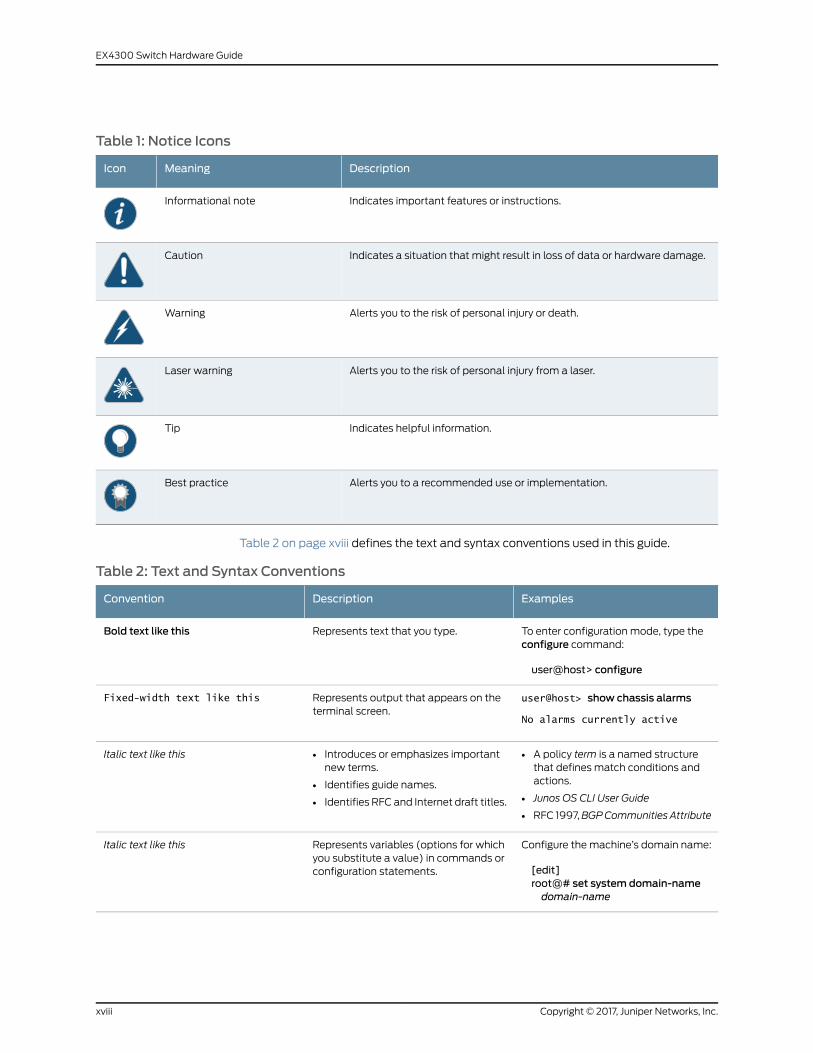
Table 1: Notice Icons
DescriptionMeaningIcon
Indicates important features or instructions.Informational note
Indicates a situation that might result in loss of data or hardware damage.Caution
Alerts you to the risk of personal injury or death.Warning
Alerts you to the risk of personal injury from a laser.Laser warning
Indicates helpful information.Tip
Alerts you to a recommended use or implementation.Best practice
Table 2 on page xviii defines the text and syntax conventions used in this guide.
Table 2: Text and Syntax Conventions
ExamplesDescriptionConvention
To enter configuration mode, type theconfigure command:
user@host> configure
Represents text that you type.Bold text like this
user@host> show chassis alarms
No alarms currently active
Represents output that appears on theterminal screen.
Fixed-width text like this
• A policy term is a named structurethat defines match conditions andactions.
• Junos OS CLI User Guide
• RFC 1997,BGPCommunities Attribute
• Introduces or emphasizes importantnew terms.
• Identifies guide names.
• Identifies RFC and Internet draft titles.
Italic text like this
Configure themachine’s domain name:
[edit]root@# set system domain-namedomain-name
Represents variables (options for whichyou substitute a value) in commands orconfiguration statements.
Italic text like this
Copyright © 2017, Juniper Networks, Inc.xviii
EX4300 Switch Hardware Guide

Table 2: Text and Syntax Conventions (continued)
ExamplesDescriptionConvention
• To configure a stub area, include thestub statement at the [edit protocolsospf area area-id] hierarchy level.
• Theconsoleport is labeledCONSOLE.
Represents names of configurationstatements, commands, files, anddirectories; configurationhierarchy levels;or labels on routing platformcomponents.
Text like this
stub <default-metricmetric>;Encloses optional keywords or variables.< > (angle brackets)
broadcast | multicast
(string1 | string2 | string3)
Indicates a choice between themutuallyexclusive keywords or variables on eitherside of the symbol. The set of choices isoften enclosed in parentheses for clarity.
| (pipe symbol)
rsvp { # Required for dynamicMPLS onlyIndicates a comment specified on thesame lineas theconfiguration statementto which it applies.
# (pound sign)
community namemembers [community-ids ]
Encloses a variable for which you cansubstitute one or more values.
[ ] (square brackets)
[edit]routing-options {static {route default {nexthop address;retain;
}}
}
Identifies a level in the configurationhierarchy.
Indention and braces ( { } )
Identifies a leaf statement at aconfiguration hierarchy level.
; (semicolon)
GUI Conventions
• In the Logical Interfaces box, selectAll Interfaces.
• To cancel the configuration, clickCancel.
Representsgraphicaluser interface(GUI)items you click or select.
Bold text like this
In the configuration editor hierarchy,select Protocols>Ospf.
Separates levels in a hierarchy of menuselections.
> (bold right angle bracket)
Documentation Feedback
We encourage you to provide feedback, comments, and suggestions so that we can
improve the documentation. You can provide feedback by using either of the following
methods:
• Online feedback rating system—On any page of the Juniper Networks TechLibrary site
athttp://www.juniper.net/techpubs/index.html, simply click the stars to rate thecontent,
and use the pop-up form to provide us with information about your experience.
Alternately, you can use the online feedback form at
http://www.juniper.net/techpubs/feedback/.
xixCopyright © 2017, Juniper Networks, Inc.
About the Documentation

• E-mail—Sendyourcommentsto [email protected]. Includethedocument
or topic name, URL or page number, and software version (if applicable).
Requesting Technical Support
Technical product support is available through the JuniperNetworksTechnicalAssistance
Center (JTAC). If you are a customer with an active J-Care or Partner Support Service
support contract, or are covered under warranty, and need post-sales technical support,
you can access our tools and resources online or open a case with JTAC.
• JTAC policies—For a complete understanding of our JTAC procedures and policies,
review the JTAC User Guide located at
http://www.juniper.net/us/en/local/pdf/resource-guides/7100059-en.pdf.
• Product warranties—For product warranty information, visit
http://www.juniper.net/support/warranty/.
• JTAC hours of operation—The JTAC centers have resources available 24 hours a day,
7 days a week, 365 days a year.
Self-Help Online Tools and Resources
For quick and easy problem resolution, Juniper Networks has designed an online
self-service portal called the Customer Support Center (CSC) that provides youwith the
following features:
• Find CSC offerings: http://www.juniper.net/customers/support/
• Search for known bugs: https://prsearch.juniper.net/
• Find product documentation: http://www.juniper.net/documentation/
• Find solutions and answer questions using our Knowledge Base: http://kb.juniper.net/
• Download the latest versions of software and review release notes:
http://www.juniper.net/customers/csc/software/
• Search technical bulletins for relevant hardware and software notifications:
http://kb.juniper.net/InfoCenter/
• Join and participate in the Juniper Networks Community Forum:
http://www.juniper.net/company/communities/
• Open a case online in the CSC Case Management tool: http://www.juniper.net/cm/
Toverify serviceentitlementbyproduct serial number, useourSerialNumberEntitlement
(SNE) Tool: https://entitlementsearch.juniper.net/entitlementsearch/
Opening a Casewith JTAC
You can open a case with JTAC on theWeb or by telephone.
• Use the Case Management tool in the CSC at http://www.juniper.net/cm/.
• Call 1-888-314-JTAC (1-888-314-5822 toll-free in the USA, Canada, and Mexico).
Copyright © 2017, Juniper Networks, Inc.xx
EX4300 Switch Hardware Guide

For international or direct-dial options in countries without toll-free numbers, see
http://www.juniper.net/support/requesting-support.html.
xxiCopyright © 2017, Juniper Networks, Inc.
About the Documentation

Copyright © 2017, Juniper Networks, Inc.xxii
EX4300 Switch Hardware Guide

PART 1
Overview
• SystemOverview on page 3
• Chassis Components and Descriptions on page 25
• Cooling System and Airflow on page 43
• Power Supplies on page 49
• Viewing System Information on page 65
1Copyright © 2017, Juniper Networks, Inc.

Copyright © 2017, Juniper Networks, Inc.2
EX4300 Switch Hardware Guide
CHAPTER 1
System Overview
• EX4300 Switches Hardware Overview on page 3
• EX4300 Switch Models on page 15
• Identifying EX4300 Switch Models on page 19
• EX4300 Switch Hardware and CLI Terminology Mapping on page 20
EX4300 Switches Hardware Overview
Juniper Networks EX4300 Ethernet Switches provide connectivity for high-density
environments and scalability for growing networks. These switches can be deployed
wherever youneedhighdensityofGigabitEthernetportsor redundancy.Typically, EX4300
switches are used in large branch offices, campus wiring closets, and data centers. In
datacenters, EX4300switchescanbepositionedas top-of-rack switches; the topdevices
in a rack to provide connectivity for all the devices in the rack and provide options for
optimized airflow (hot aisle/cold aisle).
Three variants of the EX4300 switches are available—24-port, 32-port, and 48-port
switches, with or without PoE+, with AC or DC power supplies, andwith different airflow
directions. EX4300switches alsoprovide uplink ports anda slot for installing anoptional
uplink module.
YoucanmanageEX4300switchesbyusing thesame interfaces that youuse formanaging
other devices running Juniper Networks Junos operating system (JunosOS)—theCLI, the
J-Web graphical interface, and Junos Space.
This topic describes:
• Software on page 4
• EX4300 Switches First View on page 4
• Uplink Modules on page 9
• Virtual Chassis on page 10
• Power Supplies on page 11
• Fan Modules on page 12
• EX4300 Switch Components on page 13
3Copyright © 2017, Juniper Networks, Inc.

Software
Juniper Networks EX Series Ethernet Switches run Junos OS, which provides Layer 2 and
Layer 3 switching, routing, and security services. The same JunosOS code base that runs
on EXSeries switches also runs on all Juniper NetworksMSeries, MXSeries, and TSeries
routers, and SRX Series Services Gateways.
EX4300 Switches First View
EX4300 switches provide connectivity for high-density Gigabit Ethernet data center
top-of-rack, enterprise, and campus aggregation/core deployments. EX4300 switches
can be used in large branch offices, campus wiring closets, and data centers. In data
centers, these switches can be positioned as the top devices in a rack to provide
connectivity for all devices in the rack and provide options for optimized airflow (hot
aisle/cold aisle).
To provide carrier-class reliability, EX4300 switches include:
• Dual redundant, load-sharingpowersupplies thatarehot-insertableandhot-removable
field-replaceable units (FRUs).
• Two fanmodules that are field-replaceable units.
• Redundant Routing Engines in a Virtual Chassis or QFX5100 Virtual Chassis Fabric
(VCF) configuration. This redundancy enables graceful Routing Engine switchover
(GRES).
• Junos OSwith its modular design that enables failed system processes to gracefully
restart.
The following EX4300 switches are available:
• 24-Port EX4300 Switches on page 4
• 32-Port EX4300 Switches on page 6
• 48-Port EX4300 Switches on page 7
24-Port EX4300 Switches
The 24-port EX4300 switches—EX4300-24T and EX4300-24P—provide 24 built-in
10/100/1000BASE-T Ethernet network ports and four built-in 40-Gigabit Ethernet quad
small form-factor pluggable plus (QSFP+) ports that can house 40-Gigabit QSFP+
transceivers. All network ports in the EX4300-24P switch are equipped for Power over
Ethernet (PoE+), whereas EX4300-24T has no PoE+ ports. 24-port EX4300 switches
support AC power supply and fanmodule with front-to-back airflow direction and have
a slot for installing an optional 4-port 10-Gigabit Ethernet SFP+ uplink module, which
has four 10-Gigabit Ethernet small form-factor pluggable plus (SFP+) ports that can
house four 10-gigabit small form-factor pluggable (SFP+) transceivers, four 1-gigabit
small form-factor pluggable (SFP) transceivers, or a combination of four SFP+ and SFP
transceivers.
Figure 1 on page 5 shows the front panel of a 24-port EX4300 switch.
Copyright © 2017, Juniper Networks, Inc.4
EX4300 Switch Hardware Guide

Figure 1: Front Panel of a 24-Port EX4300 Switch
Figure 2 on page 5 shows the rear panel of a 24-port EX4300 switchwith power supplies
and fanmodules installed.
Figure 2: Rear Panel of a 24-Port EX4300 Switch
Table 3 on page 5 lists the 24-port EX4300 switch models and their components.
Table 3: Components in 24-Port EX4300 Switches
SupportedUplinkModule
Power SupplyShipped by Default
FanModulesShipped by Default
Number ofPoE-enabledPortsBuilt-In PortsSwitchModels
4-port10-GigabitEthernet SFP+uplink module
A 350WAC powersupply with the AIROUT (AFO) label.
Twofanmodules; eachwith anAIROUT (AFO)label.
02410/100/1000BASE-TEthernet ports andfour QSFP+ ports
EX4300-24T
4-port10-GigabitEthernet SFP+uplink module
Power supplies forthis model are notshipped by default;you must separatelyorder either ACpowersupplies or DC powersupplies.
Fanmodules for thismodel are not shippedby default; you mustseparately order eithertwo AIR OUT (AFO)labeled or two AIR IN(AFI) labeled fanmodules.
02410/100/1000BASE-TEthernet ports andfour QSFP+ ports
EX4300-24T-S
4-port10-GigabitEthernet SFP+uplink module
A 715W AC powersupply with the AIROUT (AFO) label.
Twofanmodules; eachwith anAIROUT (AFO)label.
242410/100/1000BASE-TEthernet ports andfour QSFP+ ports
EX4300-24P
5Copyright © 2017, Juniper Networks, Inc.
Chapter 1: SystemOverview
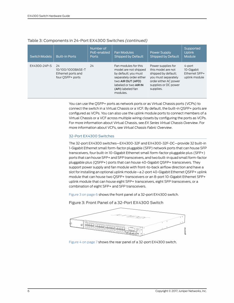
Table 3: Components in 24-Port EX4300 Switches (continued)
SupportedUplinkModule
Power SupplyShipped by Default
FanModulesShipped by Default
Number ofPoE-enabledPortsBuilt-In PortsSwitchModels
4-port10-GigabitEthernet SFP+uplink module
Power supplies forthis model are notshipped by default;you must separatelyorder either ACpowersupplies or DC powersupplies.
Fanmodules for thismodel are not shippedby default; you mustseparately order eithertwo AIR OUT (AFO)labeled or two AIR IN(AFI) labeled fanmodules.
242410/100/1000BASE-TEthernet ports andfour QSFP+ ports
EX4300-24P-S
You can use the QSFP+ ports as network ports or as Virtual Chassis ports (VCPs) to
connect the switch in a Virtual Chassis or a VCF. By default, the built-in QSFP+ ports are
configured as VCPs. You can also use the uplink module ports to connect members of a
Virtual Chassis or a VCF across multiple wiring closets by configuring the ports as VCPs.
For more information about Virtual Chassis, see EX Series Virtual Chassis Overview. For
more information about VCFs, see Virtual Chassis Fabric Overview.
32-Port EX4300 Switches
The 32-port EX4300 switches—EX4300-32F and EX4300-32F-DC—provide 32 built-in
1-Gigabit Ethernet small form-factor pluggable (SFP) network ports that can house SFP
transceivers, four built-in 10-Gigabit Ethernet small form-factor pluggable plus (SFP+)
ports that canhouseSFP+andSFP transceivers, and twobuilt-inquadsmall form-factor
pluggable plus (QSFP+) ports that can house 40-Gigabit QSFP+ transceivers. They
support power supply and fanmodule with front-to-back airflow direction and have a
slot for installing an optional uplinkmodule—a2-port 40-Gigabit EthernetQSFP+uplink
module that can house two QSFP+ transceivers or an 8-port 10-Gigabit Ethernet SFP+
uplink module that can house eight SFP+ transceivers, eight SFP transceivers, or a
combination of eight SFP+ and SFP transceivers.
Figure 3 on page 6 shows the front panel of a 32-port EX4300 switch.
Figure 3: Front Panel of a 32-Port EX4300 Switch
Figure 4 on page 7 shows the rear panel of a 32-port EX4300 switch.
Copyright © 2017, Juniper Networks, Inc.6
EX4300 Switch Hardware Guide
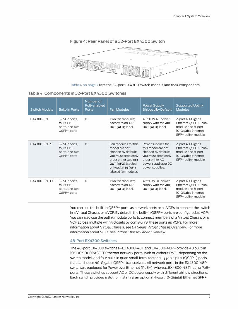
Figure 4: Rear Panel of a 32-Port EX4300 Switch
Table 4 on page 7 lists the 32-port EX4300 switch models and their components.
Table 4: Components in 32-Port EX4300 Switches
Supported UplinkModules
Power SupplyShippedbyDefaultFanModules
Number ofPoE-enabledPortsBuilt-In PortsSwitch Models
2-port 40-GigabitEthernetQSFP+uplinkmodule and 8-port10-Gigabit EthernetSFP+ uplink module
A 350WAC powersupply with the AIROUT (AFO) label.
Two fanmodules;each with an AIROUT (AFO) label.
032 SFP ports,four SFP+ports, and twoQSFP+ ports
EX4300-32F
2-port 40-GigabitEthernetQSFP+uplinkmodule and 8-port10-Gigabit EthernetSFP+ uplink module
Power supplies forthis model are notshipped by default;you must separatelyorder either ACpower suppliesorDCpower supplies.
Fanmodules for thismodel are notshipped by default;youmust separatelyorder either two AIROUT (AFO) labeledor two AIR IN (AFI)labeled fanmodules.
032 SFP ports,four SFP+ports, and twoQSFP+ ports
EX4300-32F-S
2-port 40-GigabitEthernetQSFP+uplinkmodule and 8-port10-Gigabit EthernetSFP+ uplink module
A 550WDC powersupply with the AIROUT (AFO) label.
Two fanmodules;each with an AIROUT (AFO) label.
032 SFP ports,four SFP+ports, and twoQSFP+ ports
EX4300-32F-DC
You can use the built-in QSFP+ ports as network ports or as VCPs to connect the switch
in a Virtual Chassis or a VCF. By default, the built-in QSFP+ ports are configured as VCPs.
You can also use the uplink module ports to connect members of a Virtual Chassis or a
VCF across multiple wiring closets by configuring these ports as VCPs. For more
information about Virtual Chassis, see EX Series Virtual Chassis Overview. For more
information about VCFs, see Virtual Chassis Fabric Overview.
48-Port EX4300 Switches
The 48-port EX4300 switches—EX4300-48T and EX4300-48P—provide 48 built-in
10/100/1000BASE-T Ethernet network ports, with or without PoE+ depending on the
switch model, and four built-in quad small form-factor pluggable plus (QSFP+) ports
that can house 40-Gigabit QSFP+ transceivers. All network ports in the EX4300-48P
switchare equipped forPower over Ethernet (PoE+),whereasEX4300-48ThasnoPoE+
ports. These switches support AC or DC power supply with different airflow directions.
Each switch provides a slot for installing an optional 4-port 10-Gigabit Ethernet SFP+
7Copyright © 2017, Juniper Networks, Inc.
Chapter 1: SystemOverview
uplink module, which has four SFP+ ports that can house four SFP+ transceivers, four
SFP transceivers, or a combination of four SFP+ and SFP transceivers.
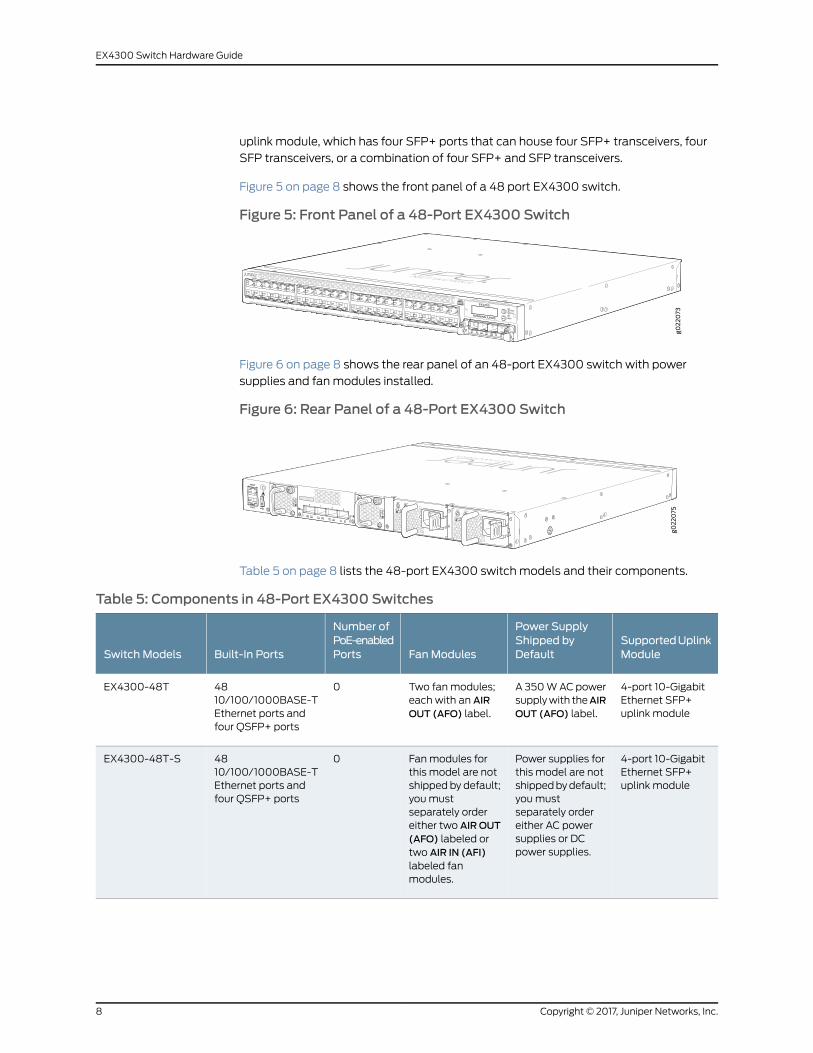
Figure 5 on page 8 shows the front panel of a 48 port EX4300 switch.
Figure 5: Front Panel of a 48-Port EX4300 Switch
Figure 6 on page 8 shows the rear panel of an 48-port EX4300 switch with power
supplies and fanmodules installed.
Figure 6: Rear Panel of a 48-Port EX4300 Switch
Table 5 on page 8 lists the 48-port EX4300 switch models and their components.
Table 5: Components in 48-Port EX4300 Switches
SupportedUplinkModule
Power SupplyShipped byDefaultFanModules
Number ofPoE-enabledPortsBuilt-In PortsSwitch Models
4-port 10-GigabitEthernet SFP+uplink module
A 350WACpowersupplywith theAIROUT (AFO) label.
Two fanmodules;each with an AIROUT (AFO) label.
04810/100/1000BASE-TEthernet ports andfour QSFP+ ports
EX4300-48T
4-port 10-GigabitEthernet SFP+uplink module
Power supplies forthis model are notshippedbydefault;you mustseparately ordereither AC powersupplies or DCpower supplies.
Fanmodules forthis model are notshipped by default;you mustseparately ordereither two AIROUT(AFO) labeled ortwo AIR IN (AFI)labeled fanmodules.
04810/100/1000BASE-TEthernet ports andfour QSFP+ ports
EX4300-48T-S
Copyright © 2017, Juniper Networks, Inc.8
EX4300 Switch Hardware Guide

Table 5: Components in 48-Port EX4300 Switches (continued)
SupportedUplinkModule
Power SupplyShipped byDefaultFanModules
Number ofPoE-enabledPortsBuilt-In PortsSwitch Models
4-port 10-GigabitEthernet SFP+uplink module
A 350WACpowersupplywith theAIRIN (AFI) label.
Two fanmodules;eachwith anAIR IN(AFI) label.
04810/100/1000BASE-TEthernet ports andfour QSFP+ ports
EX4300-48T-AFI
4-port 10-GigabitEthernet SFP+uplink module
A 550WDCpowersupplywith theAIROUT (AFO) label.
Two fanmodules;each with an AIROUT (AFO) label.
04810/100/1000BASE-TEthernet ports andfour QSFP+ ports
EX4300-48T-DC
4-port 10-GigabitEthernet SFP+uplink module
A 550WDCpowersupplywith theAIRIN (AFI) label.
Two fanmodules;eachwith anAIR IN(AFI) label.
04810/100/1000BASE-TEthernet ports andfour QSFP+ ports
EX4300-48T-DC-AFI
4-port 10-GigabitEthernet SFP+uplink module
A 1100WACpowersupplywith theAIROUT (AFO) label.
Two fanmodules;each with an AIROUT (AFO) label.
484810/100/1000BASE-TEthernet ports andfour QSFP+ ports
EX4300-48P
4-port 10-GigabitEthernet SFP+uplink module
Power supplies forthis model are notshippedbydefault;you mustseparately ordereither AC powersupplies or DCpower supplies.
Fanmodules forthis model are notshipped by default;you mustseparately ordereither two AIROUT(AFO) labeled ortwo AIR IN (AFI)labeled fanmodules.
484810/100/1000BASE-TEthernet ports andfour QSFP+ ports
EX4300-48P-S
You can use the QSFP+ ports as network ports or as VCPs to connect the switch in a
Virtual Chassis or a VCF. By default, the built-in QSFP+ ports are configured as VCPs.
You can also use the uplink module ports to connect members of a Virtual Chassis or a
VCF across multiple wiring closets by configuring these ports as VCPs. For more
information about Virtual Chassis, see EX Series Virtual Chassis Overview. For more
information about VCFs, see Virtual Chassis Fabric Overview.
Uplink Modules
EX4300 switches provide one slot for installing an optional uplink module. You can use
the uplink module ports either to connect the switch to other devices or configure these
ports as VCPs and use them to interconnect EX4300 switches to form a Virtual Chassis
or a VCF configuration by using SFP+ transceivers.
Table 6 on page 10 lists the uplink modules supported on 24-port and 48-port EX4300
switchmodels. Table 7onpage 10 lists theuplinkmodules supportedon32-port EX4300
switch models.
9Copyright © 2017, Juniper Networks, Inc.
Chapter 1: SystemOverview
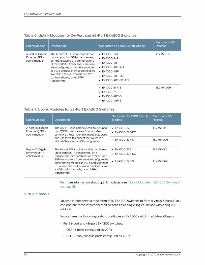
Table 6: Uplink Modules for 24-Port and 48-Port EX4300 Switches
First Junos OSReleaseSupported EX4300 Switch ModelsDescriptionUplink Module
13.2X50-D10• EX4300-24T
• EX4300-24P
• EX4300-48T
• EX4300-48T-AFI
• EX4300-48P
• EX4300-48T-DC
• EX4300-48T-DC-AFI
The 4-port SFP+ uplink module canhouse up to four SFP+ transceivers,SFP transceivers, or a combination ofSFP+ and SFP transceivers. You canalso configure ports on this moduleasVCPsanduse them to connect theswitch in a Virtual Chassis or a VCFconfiguration by using SFP+transceivers.
4-port 10-GigabitEthernet SFP+uplink module
13.2X51-D26• EX4300-24T-S
• EX4300-24P-S
• EX4300-48T-S
• EX4300-48P-S
Table 7: Uplink Modules for 32-Port EX4300 Switches
First Junos OSRelease
Supported EX4300 SwitchModelsDescriptionUplink Module
13.2X51-D15• EX4300-32F
• EX4300-32F-DC
The QSFP+ uplink module can house up totwo QSFP+ transceivers. You can alsoconfigure the ports on this module as VCPsand use them to connect the switch in aVirtual Chassis or a VCF configuration.
2-port 40-GigabitEthernet QSFP+uplink module
13.2X51-D26• EX4300-32F-S
13.2X51-D15• EX4300-32F
• EX4300-32F-DC
The 8-port SFP+ uplink module can houseup to eight SFP+ transceivers, SFPtransceivers, or a combination of SFP+ andSFP transceivers. You can also configure theports on this module as VCPs and use themto connect the switch in a Virtual Chassis ora VCF configuration by using SFP+transceivers.
8-port 10-GigabitEthernet SFP+uplink module
13.2X51-D26• EX4300-32F-S
For more information about uplink modules, see “Uplink Modules in EX4300 Switches”
on page 31.
Virtual Chassis
You can interconnect a maximum of 10 EX4300 switches to form a Virtual Chassis. You
can operate these interconnected switches as a single, logical device with a single IP
address.
You can use the following ports to configure an EX4300 switch in a Virtual Chassis:
• For 24-port and 48-port EX4300 switches:
• QSFP+ ports configured as VCPs
• SFP+ uplink module ports configured as VCPs
Copyright © 2017, Juniper Networks, Inc.10
EX4300 Switch Hardware Guide

• For 32-port EX4300 switches:
• QSFP+ ports (built-in) or QSFP+ uplink module ports configured as VCPs
• SFP+ uplink module ports configured as VCPs
NOTE: The four built-in SFP+ ports on 32-port EX4300 switches cannotbe configured as VCPs.
By default, the built-in QSFP+ ports are configured as VCPs.
Power Supplies
EX4300 switches support AC or DC power supplies with different airflow directions.
Power supplies for the EX4300 switch are fully redundant, load-sharing, and
hot-removable and hot-insertable FRUs. All the EX4300 switch models except
EX4300-24T-S, EX4300-24P-S, EX4300-32F-S, EX4300-48T-S, and EX4300-48P-S
switchesare shippedwithonepower supplypreinstalled in the rearpanelof theswitches.
EX4300-24T-S, EX4300-24P-S, EX4300-32F-S, EX4300-48T-S, and EX4300-48P-S
switches are not shipped with preinstalled power supplies; youmust order the power
supplies separately.
Each power supply has a label—AIR IN (AFI) or AIR OUT (AFO)—on the faceplate of the
power supply that indicates the direction of airflow. AIR IN (AFI) labels indicate
back-to-front airflow while AIR OUT (AFO) labels indicate front-to-back airflow.
Table 8 on page 11 lists the AC and DC power supplies used in EX4300 switches and
the direction of airflow in them.
Table 8: Airflow Direction in Power Supplies for EX4300 Switches
Direction of AirflowLabel on Power SupplyPowerSupplyRating
Back-to-front—that is, air intake to cool thechassis is through the vents on the rear panel ofthechassis andhotair exhausts through theventson the front panel of the chassis.
AIR IN (AFI)350WAC
Front-to-back—that is, air intake to cool thechassis is through the vents on the front panel ofthechassis andhotair exhausts through theventson the rear panel of the chassis.
AIR OUT (AFO)350WAC
Back-to-front—that is, air intake to cool thechassis is through the vents on the rear panel ofthechassis andhotair exhausts through theventson the front panel of the chassis.
AIR IN (AFI)550WDC
Front-to-back—that is, air intake to cool thechassis is through the vents on the front panel ofthechassis andhotair exhausts through theventson the rear panel of the chassis.
AIR OUT (AFO)550WDC
11Copyright © 2017, Juniper Networks, Inc.
Chapter 1: SystemOverview
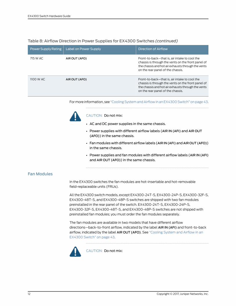
Table 8: Airflow Direction in Power Supplies for EX4300 Switches (continued)
Direction of AirflowLabel on Power SupplyPowerSupplyRating
Front-to-back—that is, air intake to cool thechassis is through the vents on the front panel ofthechassis andhotair exhausts through theventson the rear panel of the chassis.
AIR OUT (AFO)715W AC
Front-to-back—that is, air intake to cool thechassis is through the vents on the front panel ofthechassis andhotair exhausts through theventson the rear panel of the chassis.
AIR OUT (AFO)1100WAC
Formore information, see “CoolingSystemandAirflow inanEX4300Switch”onpage43.
CAUTION: Do notmix:
• AC and DC power supplies in the same chassis.
• Power supplies with different airflow labels (AIR IN (AFI) and AIR OUT
(AFO)) in the same chassis.
• Fanmoduleswith different airflow labels (AIR IN (AFI)andAIROUT(AFO))
in the same chassis.
• Power supplies and fanmodules with different airflow labels (AIR IN (AFI)
and AIR OUT (AFO)) in the same chassis.
FanModules
In the EX4300 switches the fanmodules are hot-insertable and hot-removable
field-replaceable units (FRUs).
All the EX4300 switchmodels, except EX4300-24T-S, EX4300-24P-S, EX4300-32F-S,
EX4300-48T-S, and EX4300-48P-S switches are shipped with two fanmodules
preinstalled in the rear panel of the switch. EX4300-24T-S, EX4300-24P-S,
EX4300-32F-S, EX4300-48T-S, and EX4300-48P-S switches are not shipped with
preinstalled fanmodules; youmust order the fanmodules separately.
The fanmodules are available in twomodels that have different airflow
directions—back-to-front airflow, indicated by the label AIR IN (AFI) and front-to-back
airflow, indicated by the label AIR OUT (AFO). See “Cooling System and Airflow in an
EX4300 Switch” on page 43.
CAUTION: Do notmix:
Copyright © 2017, Juniper Networks, Inc.12
EX4300 Switch Hardware Guide
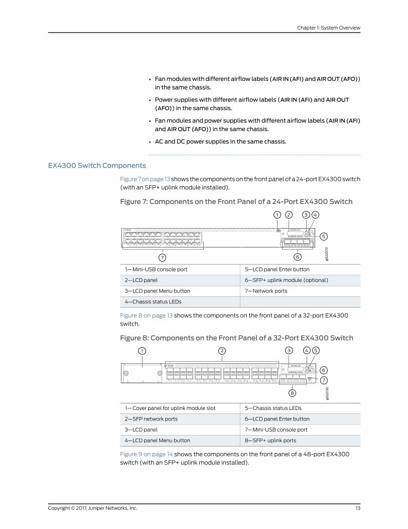
• Fanmoduleswith different airflow labels (AIR IN (AFI)andAIROUT(AFO))
in the same chassis.
• Power supplies with different airflow labels (AIR IN (AFI) and AIR OUT
(AFO)) in the same chassis.
• Fanmodules and power supplieswith different airflow labels (AIR IN (AFI)
and AIR OUT (AFO)) in the same chassis.
• AC and DC power supplies in the same chassis.
EX4300 Switch Components
Figure 7onpage 13 shows thecomponentson the frontpanelofa24-portEX4300switch
(with an SFP+ uplink module installed).
Figure 7: Components on the Front Panel of a 24-Port EX4300 Switch
5—1— LCD panel Enter buttonMini-USB console port
6—2— SFP+ uplink module (optional)LCD panel
7—3— Network portsLCD panel Menu button
4—Chassis status LEDs
Figure 8 on page 13 shows the components on the front panel of a 32-port EX4300
switch.
Figure 8: Components on the Front Panel of a 32-Port EX4300 Switch
5—1— Chassis status LEDsCover panel for uplink module slot
6—2— LCD panel Enter buttonSFP network ports
7—3— Mini-USB console portLCD panel
8—4— SFP+ uplink portsLCD panel Menu button
Figure 9 on page 14 shows the components on the front panel of a 48-port EX4300
switch (with an SFP+ uplink module installed).
13Copyright © 2017, Juniper Networks, Inc.
Chapter 1: SystemOverview

Figure 9: Components on the Front Panel of a 48-Port EX4300 Switch
5—1— LCD panel Enter buttonMini-USB console port
6—2— SFP+ uplink module (optional)LCD panel
7—3— Network portsLCD panel Menu button
4—Chassis status LEDs
Figure 10 on page 14 shows the components on the rear panel of a 24-port and 48-port
EX4300 switch (with two AC power supplies and two fanmodules installed).
Figure 10: Components on the Rear Panel of a 24-Port and 48-PortEX4300 Switch
8—1— AC power supply in slot 1Management port
9—2— Power supply slot numbersESD point
10—3— Fanmodule slot numbers and LEDsFanmodule in slot 0
11—4— QSFP+ port LEDsSerial number label
12—5— USB portQSFP+ ports
13—6— Console portFanmodule in slot 1
7—AC power supply in slot 0
NOTE: DC power supplies are installed in the power supply slots in modelsthat use DC power.
Figure 11 onpage 15 shows the components on the rear panel of a 32-port EX4300switch
(with two AC power supplies and two fanmodules installed).
Copyright © 2017, Juniper Networks, Inc.14
EX4300 Switch Hardware Guide
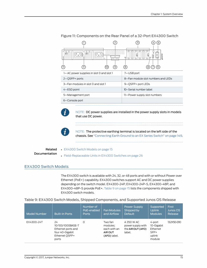
Figure 11: Components on the Rear Panel of a 32-Port EX4300 Switch
7—1— USB portAC power supplies in slot 0 and slot 1
8—2— Fanmodule slot numbers and LEDsQSFP+ ports
9—3— QSFP+ port LEDsFanmodules in slot 0 and slot 1
10—4— Serial number labelESD point
11—5— Power supply slot numbersManagement port
6—Console port
NOTE: DC power supplies are installed in the power supply slots in modelsthat use DC power.
NOTE: The protective earthing terminal is located on the left side of thechassis. See “Connecting Earth Ground to an EX Series Switch” on page 149.
RelatedDocumentation
EX4300 Switch Models on page 15•
• Field-Replaceable Units in EX4300 Switches on page 26
EX4300 SwitchModels
The EX4300 switch is available with 24, 32, or 48 ports and with or without Power over
Ethernet (PoE+) capability. EX4300 switches support AC and DC power supplies
depending on the switch model. EX4300-24P, EX4300-24P-S, EX4300-48P, and
EX4300-48P-S provide PoE+. Table 9 on page 15 lists the components shipped with
EX4300 switch models.
Table 9: EX4300 SwitchModels, Shipped Components, and Supported Junos OS Release
FirstJunos OSRelease
SupportedUplinkModules
Power SupplyShipped byDefault
FanModulesand Airflow
Number ofPoE-enabledPortsBuilt-In PortsModel Number
13.2X50-D104-port10-GigabitEthernetSFP+uplinkmodule
A 350WACpower supplywiththeAIROUT(AFO)label.
Two fanmodules;each with anAIR OUT(AFO) label.
02410/100/1000BASE-TEthernet ports andfour 40-GigabitEthernet QSFP+ports
EX4300-24T
15Copyright © 2017, Juniper Networks, Inc.
Chapter 1: SystemOverview
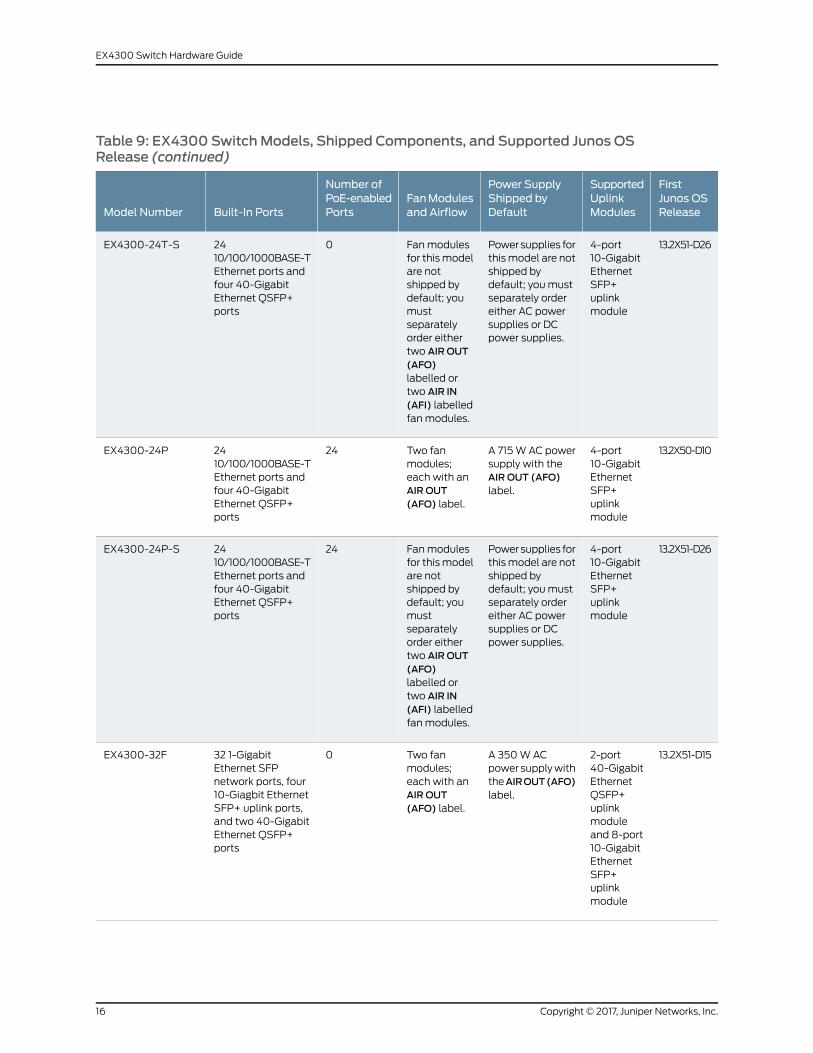
Table 9: EX4300 SwitchModels, Shipped Components, and Supported Junos OSRelease (continued)
FirstJunos OSRelease
SupportedUplinkModules
Power SupplyShipped byDefault
FanModulesand Airflow
Number ofPoE-enabledPortsBuilt-In PortsModel Number
13.2X51-D264-port10-GigabitEthernetSFP+uplinkmodule
Power supplies forthismodel are notshipped bydefault; you mustseparately ordereither AC powersupplies or DCpower supplies.
Fanmodulesfor thismodelare notshipped bydefault; youmustseparatelyorder eithertwo AIR OUT(AFO)labelled ortwo AIR IN(AFI) labelledfanmodules.
02410/100/1000BASE-TEthernet ports andfour 40-GigabitEthernet QSFP+ports
EX4300-24T-S
13.2X50-D104-port10-GigabitEthernetSFP+uplinkmodule
A 715WAC powersupply with theAIR OUT (AFO)label.
Two fanmodules;each with anAIR OUT(AFO) label.
242410/100/1000BASE-TEthernet ports andfour 40-GigabitEthernet QSFP+ports
EX4300-24P
13.2X51-D264-port10-GigabitEthernetSFP+uplinkmodule
Power supplies forthismodel are notshipped bydefault; you mustseparately ordereither AC powersupplies or DCpower supplies.
Fanmodulesfor thismodelare notshipped bydefault; youmustseparatelyorder eithertwo AIR OUT(AFO)labelled ortwo AIR IN(AFI) labelledfanmodules.
242410/100/1000BASE-TEthernet ports andfour 40-GigabitEthernet QSFP+ports
EX4300-24P-S
13.2X51-D152-port40-GigabitEthernetQSFP+uplinkmoduleand 8-port10-GigabitEthernetSFP+uplinkmodule
A 350WACpower supplywiththeAIROUT(AFO)label.
Two fanmodules;each with anAIR OUT(AFO) label.
032 1-GigabitEthernet SFPnetwork ports, four10-Giagbit EthernetSFP+ uplink ports,and two 40-GigabitEthernet QSFP+ports
EX4300-32F
Copyright © 2017, Juniper Networks, Inc.16
EX4300 Switch Hardware Guide
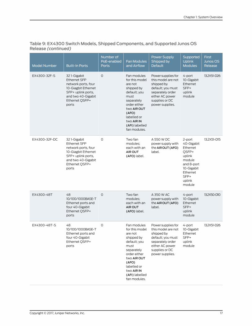
Table 9: EX4300 SwitchModels, Shipped Components, and Supported Junos OSRelease (continued)
FirstJunos OSRelease
SupportedUplinkModules
Power SupplyShipped byDefault
FanModulesand Airflow
Number ofPoE-enabledPortsBuilt-In PortsModel Number
13.2X51-D264-port10-GigabitEthernetSFP+uplinkmodule
Power supplies forthismodel are notshipped bydefault; you mustseparately ordereither AC powersupplies or DCpower supplies.
Fanmodulesfor thismodelare notshipped bydefault; youmustseparatelyorder eithertwo AIR OUT(AFO)labelled ortwo AIR IN(AFI) labelledfanmodules.
032 1-GigabitEthernet SFPnetwork ports, four10-Giagbit EthernetSFP+ uplink ports,and two 40-GigabitEthernet QSFP+ports
EX4300-32F-S
13.2X51-D152-port40-GigabitEthernetQSFP+uplinkmoduleand 8-port10-GigabitEthernetSFP+uplinkmodule
A 550WDCpower supplywiththeAIROUT(AFO)label.
Two fanmodules;each with anAIR OUT(AFO) label.
032 1-GigabitEthernet SFPnetwork ports, four10-Giagbit EthernetSFP+ uplink ports,and two 40-GigabitEthernet QSFP+ports
EX4300-32F-DC
13.2X50-D104-port10-GigabitEthernetSFP+uplinkmodule
A 350WACpower supplywiththeAIROUT(AFO)label.
Two fanmodules;each with anAIR OUT(AFO) label.
04810/100/1000BASE-TEthernet ports andfour 40-GigabitEthernet QSFP+ports
EX4300-48T
13.2X51-D264-port10-GigabitEthernetSFP+uplinkmodule
Power supplies forthismodel are notshipped bydefault; you mustseparately ordereither AC powersupplies or DCpower supplies.
Fanmodulesfor thismodelare notshipped bydefault; youmustseparatelyorder eithertwo AIR OUT(AFO)labelled ortwo AIR IN(AFI) labelledfanmodules.
04810/100/1000BASE-TEthernet ports andfour 40-GigabitEthernet QSFP+ports
EX4300-48T-S
17Copyright © 2017, Juniper Networks, Inc.
Chapter 1: SystemOverview
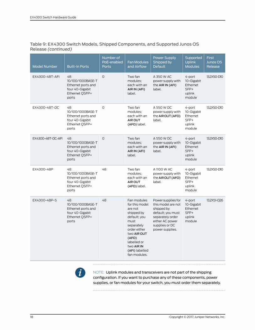
Table 9: EX4300 SwitchModels, Shipped Components, and Supported Junos OSRelease (continued)
FirstJunos OSRelease
SupportedUplinkModules
Power SupplyShipped byDefault
FanModulesand Airflow
Number ofPoE-enabledPortsBuilt-In PortsModel Number
13.2X50-D104-port10-GigabitEthernetSFP+uplinkmodule
A 350WACpower supplywiththe AIR IN (AFI)label.
Two fanmodules;each with anAIR IN (AFI)label.
04810/100/1000BASE-TEthernet ports andfour 40-GigabitEthernet QSFP+ports
EX4300-48T-AFI
13.2X50-D104-port10-GigabitEthernetSFP+uplinkmodule
A 550WDCpower supplywiththeAIROUT(AFO)label.
Two fanmodules;each with anAIR OUT(AFO) label.
04810/100/1000BASE-TEthernet ports andfour 40-GigabitEthernet QSFP+ports
EX4300-48T-DC
13.2X50-D104-port10-GigabitEthernetSFP+uplinkmodule
A 550WDCpower supplywiththe AIR IN (AFI)label.
Two fanmodules;each with anAIR IN (AFI)label.
04810/100/1000BASE-TEthernet ports andfour 40-GigabitEthernet QSFP+ports
EX4300-48T-DC-AFI
13.2X50-D104-port10-GigabitEthernetSFP+uplinkmodule
A 1100WACpower supplywiththeAIROUT(AFO)label.
Two fanmodules;each with anAIR OUT(AFO) label.
484810/100/1000BASE-TEthernet ports andfour 40-GigabitEthernet QSFP+ports
EX4300-48P
13.2X51-D264-port10-GigabitEthernetSFP+uplinkmodule
Power supplies forthismodel are notshipped bydefault; you mustseparately ordereither AC powersupplies or DCpower supplies.
Fanmodulesfor thismodelare notshipped bydefault; youmustseparatelyorder eithertwo AIR OUT(AFO)labelled ortwo AIR IN(AFI) labelledfanmodules.
484810/100/1000BASE-TEthernet ports andfour 40-GigabitEthernet QSFP+ports
EX4300-48P-S
NOTE: Uplinkmodules and transceivers are not part of the shippingconfiguration. If you want to purchase any of these components, powersupplies, or fanmodules for your switch, youmust order them separately.
Copyright © 2017, Juniper Networks, Inc.18
EX4300 Switch Hardware Guide

RelatedDocumentation
Chassis Physical Specifications for EX4300 Switches on page 25•
• EX4300 Switches Hardware Overview on page 3
Identifying EX4300 SwitchModels
Purpose Identify the model number of your EX4300 switch.
Action Check the valueof theFRUModelNumber field in theRoutingEngine section in theoutput
of the show chassis hardware extensive CLI command.
user@switch> show chassis hardware extensive
....Routing Engine 1 REV D 650-044930 PD3113060024 EX4300-48P Jedec Code: 0x7fb0 EEPROM Version: 0x02 P/N: 650-044930 S/N: PD3113060024 Assembly ID: 0x0b5e Assembly Version: 03.19 Date: 02-19-2013 Assembly Flags: 0x00 Version: REV D CLEI Code: ID: EX4300-48P FRU Model Number: EX4300-48P....
Themodel number of your switch is one of the following:
• EX4300-24T
• EX4300-24P
• EX4300-32F
• EX4300-32F-DC
• EX4300-48T
• EX4300-48T-AFI
• EX4300-48T-DC
• EX4300-48T-DC-AFI
• EX4300-48P
In the sample output, the switch model is EX4300-48P.
Meaning In EX4300 switch model numbers:
• The 24T, 24P, 32F, 48T, and 48P in the model number indicate the type of network
ports on the switch:
• 24T—The switch has 24 10/100/1000BASE-T Ethernet network ports.
• 24P—The switch has 24 10/100/1000BASE-T Ethernet network ports with all ports
equipped for Power over Ethernet (PoE+).
• 32F—The switch has 32 1-Gigabit SFP network ports.
19Copyright © 2017, Juniper Networks, Inc.
Chapter 1: SystemOverview

• 48T—The switch has 48 10/100/1000BASE-T Ethernet network ports.
• 48P—The switch has 48 10/100/1000BASE-T Ethernet network ports with all ports
equipped for PoE+.
• AFI indicates that the switch is shipped with two fanmodules and a power supply,
eachbearinganAIR IN(AFI) label. Switches thatdonothaveAFI in theirmodel numbers
ship with two fanmodules and a power supply, each bearing an AIR OUT (AFO) label.
The labels on the fanmodules and the power supplies indicate the direction of airflow
they providewithin the chassiswhen installed in the switch.AIR IN(AFI) labels indicate
back-to-front airflow, and AIR OUT (AFO) labels indicate front-to-back airflow.
• The DC in the model number indicates that the switch model works on DC power
supply. Switches that donot haveDC in theirmodel numbersworkonACpower supply.
RelatedDocumentation
EX4300 Switch Models on page 15•
EX4300 Switch Hardware and CLI TerminologyMapping
This topic describes the hardware terms used in EX4300 switch documentation and the
corresponding terms used in the Junos OS CLI. See Table 10 on page 20.
Table 10: CLI Equivalents of Terms Used in the Documentation for EX4300 Switches
Additional InformationItem In DocumentationValueDescription (CLI)HardwareItem (CLI)
“Identifying EX4300Switch Models” onpage 19
Switch chassis–One of the following:
• EX4300-24T
• EX4300-24P
• EX4300-32F
• EX4300-48T
• EX4300-48P
Chassis
–Routing Enginen is a value in the range 0through 9.
• Onastandaloneswitch,the default value is 0.
• On a Virtual Chassisconfiguration, thevalues correspond tothe member IDs ofswitches configured inthe master role and thebackup role in theVirtual Chassis.
One of the following:
• EX4300-24T
• EX4300-24P
• EX4300-32F
• EX4300-48T
• EX4300-48P
RoutingEngine (n)
Copyright © 2017, Juniper Networks, Inc.20
EX4300 Switch Hardware Guide
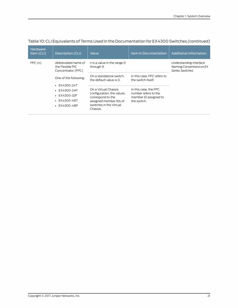
Table 10:CLIEquivalentsofTermsUsed in theDocumentation forEX4300Switches(continued)
Additional InformationItem In DocumentationValueDescription (CLI)HardwareItem (CLI)
Understanding InterfaceNamingConventionsonEXSeries Switches
n is a value in the range 0through 9.
Abbreviated name ofthe Flexible PICConcentrator (FPC)
One of the following:
• EX4300-24T
• EX4300-24P
• EX4300-32F
• EX4300-48T
• EX4300-48P
FPC (n)
In this case, FPC refers tothe switch itself.
On a standalone switch,the default value is 0.
In this case, the FPCnumber refers to themember ID assigned tothe switch.
On a Virtual Chassisconfiguration, the valuescorrespond to theassignedmember IDs ofswitches in the VirtualChassis.
21Copyright © 2017, Juniper Networks, Inc.
Chapter 1: SystemOverview
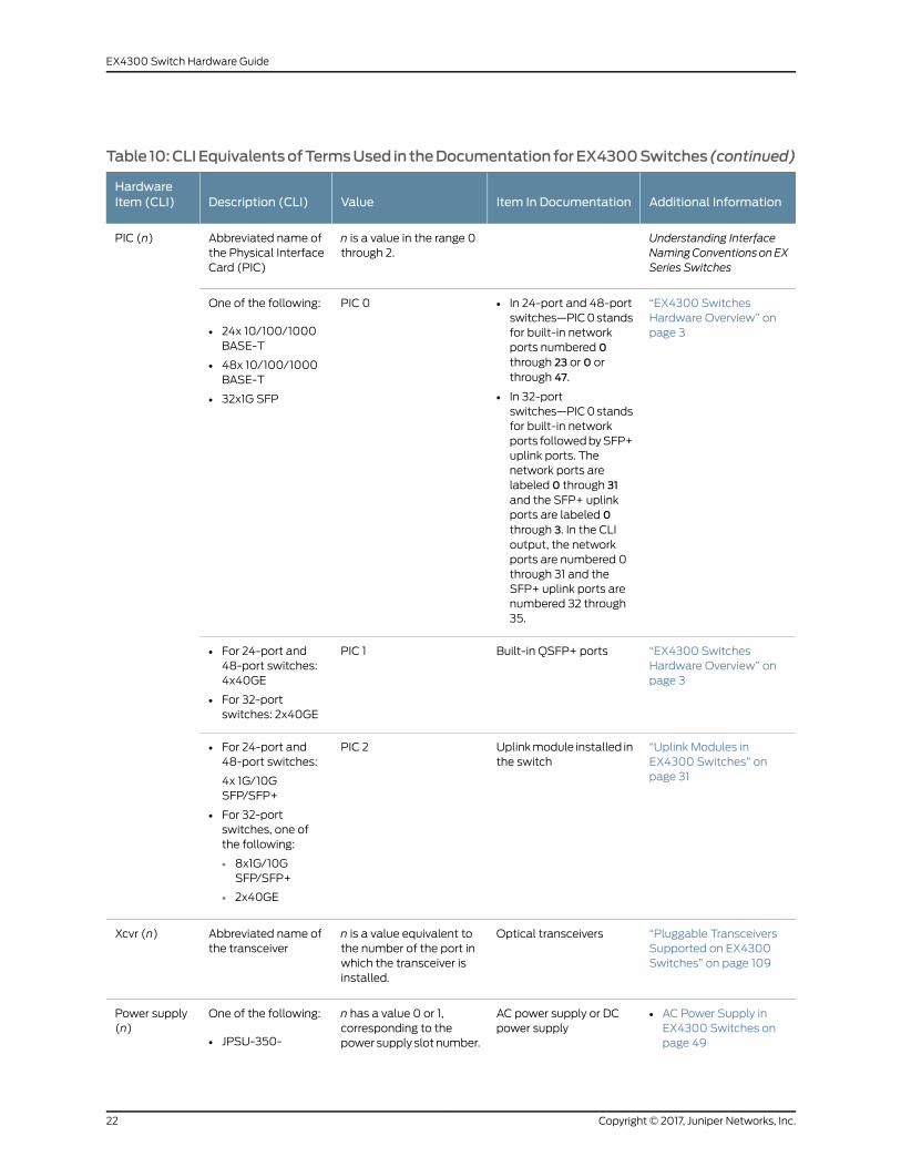
Table 10:CLIEquivalentsofTermsUsed in theDocumentation forEX4300Switches(continued)
Additional InformationItem In DocumentationValueDescription (CLI)HardwareItem (CLI)
Understanding InterfaceNamingConventionsonEXSeries Switches
n is a value in the range 0through 2.
Abbreviated name ofthe Physical InterfaceCard (PIC)
PIC (n)
“EX4300 SwitchesHardware Overview” onpage 3
• In 24-port and 48-portswitches—PIC0standsfor built-in networkports numbered 0through 23 or 0 orthrough 47.
• In 32-portswitches—PIC0standsfor built-in networkports followedbySFP+uplink ports. Thenetwork ports arelabeled 0 through 31and the SFP+ uplinkports are labeled 0through 3. In the CLIoutput, the networkports are numbered 0through 31 and theSFP+ uplink ports arenumbered 32 through35.
PIC 0One of the following:
• 24x 10/100/1000BASE-T
• 48x 10/100/1000BASE-T
• 32x1G SFP
“EX4300 SwitchesHardware Overview” onpage 3
Built-in QSFP+ portsPIC 1• For 24-port and48-port switches:4x40GE
• For 32-portswitches: 2x40GE
“Uplink Modules inEX4300 Switches” onpage 31
Uplinkmodule installed inthe switch
PIC 2• For 24-port and48-port switches:
4x 1G/10GSFP/SFP+
• For 32-portswitches, one ofthe following:
• 8x1G/10GSFP/SFP+
• 2x40GE
“Pluggable TransceiversSupported on EX4300Switches” on page 109
Optical transceiversn is a value equivalent tothe number of the port inwhich the transceiver isinstalled.
Abbreviated name ofthe transceiver
Xcvr (n)
AC power supply or DCpower supply
n has a value 0 or 1,corresponding to thepower supply slot number.
One of the following:Power supply(n)
• AC Power Supply inEX4300 Switches onpage 49• JPSU-350-
Copyright © 2017, Juniper Networks, Inc.22
EX4300 Switch Hardware Guide
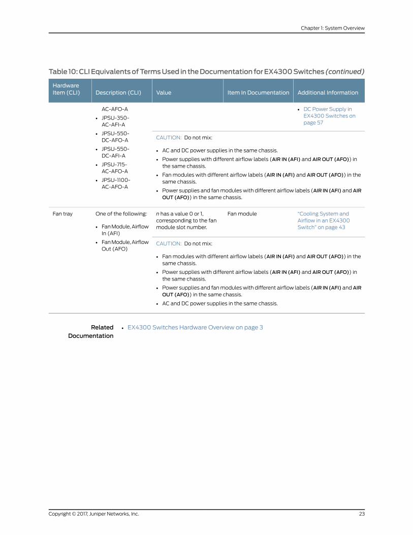
Table 10:CLIEquivalentsofTermsUsed in theDocumentation forEX4300Switches(continued)
Additional InformationItem In DocumentationValueDescription (CLI)HardwareItem (CLI)
AC-AFO-A • DC Power Supply inEX4300 Switches onpage 57
• JPSU-350-AC-AFI-A
• JPSU-550-DC-AFO-A CAUTION: Do not mix:
• AC and DC power supplies in the same chassis.
• Power supplies with different airflow labels (AIR IN (AFI) and AIR OUT (AFO)) inthe same chassis.
• Fanmodules with different airflow labels (AIR IN (AFI) and AIR OUT (AFO)) in thesame chassis.
• Power supplies and fanmoduleswith different airflow labels (AIR IN (AFI) andAIROUT (AFO)) in the same chassis.
• JPSU-550-DC-AFI-A
• JPSU-715-AC-AFO-A
• JPSU-1100-AC-AFO-A
“Cooling System andAirflow in an EX4300Switch” on page 43
Fanmodulen has a value 0 or 1,corresponding to the fanmodule slot number.
One of the following:
• FanModule,AirflowIn (AFI)
• FanModule,AirflowOut (AFO)
Fan tray
CAUTION: Do not mix:
• Fanmodules with different airflow labels (AIR IN (AFI) and AIR OUT (AFO)) in thesame chassis.
• Power supplies with different airflow labels (AIR IN (AFI) and AIR OUT (AFO)) inthe same chassis.
• Power supplies and fanmoduleswith different airflow labels (AIR IN (AFI) andAIROUT (AFO)) in the same chassis.
• AC and DC power supplies in the same chassis.
RelatedDocumentation
• EX4300 Switches Hardware Overview on page 3
23Copyright © 2017, Juniper Networks, Inc.
Chapter 1: SystemOverview

Copyright © 2017, Juniper Networks, Inc.24
EX4300 Switch Hardware Guide

CHAPTER 2
Chassis Components and Descriptions
• Chassis Physical Specifications for EX4300 Switches on page 25
• Field-Replaceable Units in EX4300 Switches on page 26
• LCD Panel in EX4300 Switches on page 27
• Uplink Modules in EX4300 Switches on page 31
• Chassis Status LEDs on EX4300 Switches on page 36
• Management Port LEDs on EX4300 Switches on page 38
• NetworkPort,Built-InQSFP+Port,UplinkPort, andUplinkModulePortLEDsonEX4300
Switches on page 39
Chassis Physical Specifications for EX4300 Switches
The EX4300 switch chassis is a rigid sheet-metal structure that houses all components
of the switch. Table 11 on page 25 summarizes the physical specifications of the EX4300
switch chassis.
Table 11: Physical Specifications of the EX4300 Switch Chassis
ValueDescription
1.72 in. (4.37 cm)Chassis height
• 17.36 in. (44.09 cm)
• The outer edges of the front-mounting brackets extend thewidth to 19 in. (48.2 cm)
Chassis width
• 16.38 in. (41.61 cm)
• With power supply and uplink module installed: 18.01 in. (45.76 cm)
Chassis depth
• EX4300 switch (with no power supply and no fanmodule installed): 13 lb (5.9 kg)
• 350WAC power supply: 2.4 lb (1.1 kg)
• 550WDC power supply: 2.4 lb (1.1 kg)
• 715W AC power supply: 2.4 lb (1.1 kg)
• 1100WAC power supply: 2.4 lb (1.1 kg)
• QSFP+ uplink module: 0.61 lb (0.28 kg)
• 4-port SFP+ uplink module: 0.44 lb (0.2 kg)
• 8-port SFP+ uplink module: 0.74 lb (0.34 kg)
• Fanmodule: 0.33 lb (0.15 kg)
Weight
25Copyright © 2017, Juniper Networks, Inc.
You canmount an EX4300 switch on a standard 19-in. two-post or four-post rack. You
can also mount the switch in a standard 19-in. enclosed cabinet.
RelatedDocumentation
Rack Requirements on page 93•
• Cabinet Requirements on page 94
• Mounting an EX4300 Switch on page 138
• Installing and Connecting an EX4300 Switch on page 137
• Installing and Removing EX4300 Switch Hardware Components on page 147
Field-Replaceable Units in EX4300 Switches
Field-replaceable units (FRUs) are components that you can replace at your site. The
FRUs in EX4300 switches are hot-removable and hot-insertable: You can remove and
replace themwithout powering off the switch. The FRUs in EX4300 switches are:
• Power supplies
• Fanmodules
• Uplink module
• Transceivers
Copyright © 2017, Juniper Networks, Inc.26
EX4300 Switch Hardware Guide
NOTE:
The following switchmodels shipwith one power supply (ACor DC) and twofanmodules preinstalled:
• EX4300-24T
• EX4300-24P
• EX4300-32F
• EX4300-32F-DC
• EX4300-48T
• EX4300-48T-AFI
• EX4300-48P
• EX4300-48T-DC
• EX4300-48T-DC-AFI
The following switchmodels ship without any power supply or fanmodulespreinstalled:
• EX4300-24T-S
• EX4300-24P-S
• EX4300-48T-S
• EX4300-48P-S
Uplink modules and transceivers are not part of the shipping configuration.If you want to purchase any of these components, power supplies, or fanmodules for your switch, youmust order them separately.
NOTE: If you have a Juniper J-Care service contract, register any addition,change, or upgrade of hardware components athttps://www.juniper.net/customers/support/tools/updateinstallbase/ . Failure
to do so can result in significant delays if you need replacement parts. Thisnote does not apply if you replace existing components with the same typeof component.
RelatedDocumentation
Installing and Removing EX4300 Switch Hardware Components on page 147•
LCD Panel in EX4300 Switches
The LCD panel on the front panel of the EX4300 switch shows two lines of text, each
with amaximumof 16 characters. The LCD panel displays a variety of information about
27Copyright © 2017, Juniper Networks, Inc.
Chapter 2: Chassis Components and Descriptions

the switch and also provides amenu to perform basic operations such as initial setup
and reboot.
There are two navigation buttons—Menu and Enter—to the right of the LCD panel.
See Figure 12 on page 28.
Figure 12: LCD Panel in EX4300 Switches
3—1— LCD panel Menu buttonLCD panel
4—2— Chassis status LEDsLCD panel Enter button
The first line of text on the LCD panel displays basic information about the switch and
the second line of text displays information about the mode selected on the LCD panel.
You can configure the second line of the text for the LCD panel to display a custom
message. If the LCD panel is configured to display a custommessage, the Menu button
and the Enter button are disabled. See “Configuring the LCDPanel on EXSeries Switches
(CLI Procedure)” on page 195.
The LCDpanel has a backlight. If the LCDpanel is idle for 60 seconds, the backlight turns
off. Youcan turnon thebacklight bypressing theMenuor Enter buttononce. After turning
on the backlight, you can toggle between the LCD panel menus by pressing the Menu
button and navigate through themenu options by pressing the Enter button.
NOTE: Thechassis viewer in the J-Web interfacealsodisplays theLCDpanel.From the J-Web interface, you can view real-time status information in theLCD panel. See “Dashboard for EX Series Switches” on page 65.
This topic describes:
• LCD Panel Modes on page 28
• LCD Panel Menus on page 29
LCD Panel Modes
The LCD panel operates in four modes: boot, idle, status, andmaintenance.
The first line of text on the LCD panel displays the slot number, the role of the switch,
and hostname in all the modes.
For a standalone EX4300 switch, by default the slot number is 00, and the role is RE.
In an EX4300 switch that is amember of a Virtual Chassis, the first line of the LCD panel
always displays:
Copyright © 2017, Juniper Networks, Inc.28
EX4300 Switch Hardware Guide

• The slot number (the member ID of the Virtual Chassis member)
• Role of the switch in the Virtual Chassis (RE for master, BK for backup, and LC for line
card member)
• Hostname
TheLCDpanel operates inbootmodeduring switch reboot. In thebootmode, the second
line of the LCD panel displays the key milestones in the switch boot process. The boot
mode does not have any menu options. After the boot process is complete, the LCD
panel automatically reverts to the Idle (IDLE) menu.
In idle mode, the second line of text on the LCD panel displays the mode of the network
ports’ Status LED and the number of chassis alarms. The number of alarms is updated
every second.
In status mode, the second line displays:
• Status of the Virtual Chassis port (VCP)
• Status of the power supplies
• Status of the fanmodules and the chassis temperature
• Version of Junos OS for EX Series switches loaded on the switch
In maintenancemode, the second line displays one of the following options, which you
can use to configure and troubleshoot the switch:
• System halt
• System reboot
• Load rescue
• Request VC port
• Factory default
• EZSetup
LCD Panel Menus
The LCD panel has threemenus: Idle, Status, andMaintenance. You can toggle between
theLCDpanelmenusbypressing theMenubuttonandnavigate through themenuoptions
by pressing the Enter button.
Table 12 on page 30 describes the LCD panel menu options.
29Copyright © 2017, Juniper Networks, Inc.
Chapter 2: Chassis Components and Descriptions

Table 12: LCD Panel Menu Options in EX4300 Switches
DescriptionMenu Label
In the Idle menu:
• Press Enter to cycle through the Status LEDmodes, which are port status indicators:
• ADM (administrative status)
• DPX (duplex)
• SPD (speed)
• POE(Powerover Ethernet) (only for EX4300-24P, EX4300-24P-S, EX4300-48P, andEX4300-48P-Smodels)
See “Network Port, Built-In QSFP+ Port, Uplink Port, and UplinkModule Port LEDs on EX4300Switches”on page 39 for information about the Status LEDmodes.
• Press Menu to exit the Idle menu and go to the Status menu.
IDLE
In the Status menu, press Menu to cycle through the following information:
• VCPs status: Up or Down
Display the status of VCPs on the switch. This option is supported only on EX4300 switches in a VirtualChassis configuration. This option is not supported on standalone EX4300 switches.
• Power supply status: OK, Failed, or Absent
• Fan status and Temperature status.
• Fan status: OK, Failed, or Absent
• Temp status: OK, High, or Shutdown
• Junos OS version for EX Series switches loaded on the switches.
• EXIT STATMENU?
Choose one of the following:
• Press Enter to exit the Status menu and go to the Maintenancemenu.
• Press Menu to display the VCPs status again.
You can disable the Status menu or the options in the Status menu in the LCD panel. See “Configuring theLCD Panel on EX Series Switches (CLI Procedure)” on page 195.
STATUS
Copyright © 2017, Juniper Networks, Inc.30
EX4300 Switch Hardware Guide
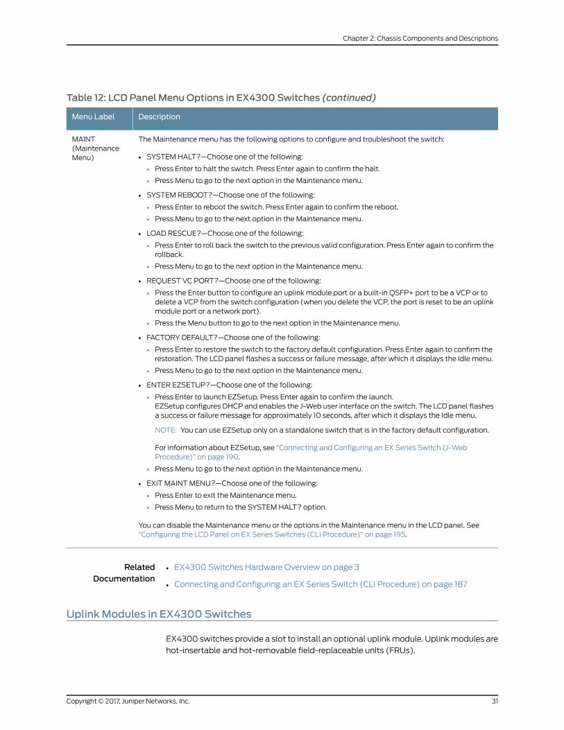
Table 12: LCD Panel Menu Options in EX4300 Switches (continued)
DescriptionMenu Label
The Maintenancemenu has the following options to configure and troubleshoot the switch:
• SYSTEMHALT?—Choose one of the following:
• Press Enter to halt the switch. Press Enter again to confirm the halt.
• Press Menu to go to the next option in the Maintenancemenu.
• SYSTEM REBOOT?—Choose one of the following:
• Press Enter to reboot the switch. Press Enter again to confirm the reboot.
• Press Menu to go to the next option in the Maintenancemenu.
• LOAD RESCUE?—Choose one of the following:
• Press Enter to roll back the switch to the previous valid configuration. Press Enter again to confirm therollback.
• Press Menu to go to the next option in the Maintenancemenu.
• REQUEST VC PORT?—Choose one of the following:
• Press the Enter button to configure an uplink module port or a built-in QSFP+ port to be a VCP or todelete a VCP from the switch configuration (when you delete the VCP, the port is reset to be an uplinkmodule port or a network port).
• Press the Menu button to go to the next option in the Maintenancemenu.
• FACTORY DEFAULT?—Choose one of the following:
• Press Enter to restore the switch to the factory default configuration. Press Enter again to confirm therestoration. The LCD panel flashes a success or failure message, after which it displays the Idle menu.
• Press Menu to go to the next option in the Maintenancemenu.
• ENTER EZSETUP?—Choose one of the following:
• Press Enter to launch EZSetup. Press Enter again to confirm the launch.EZSetup configures DHCP and enables the J-Web user interface on the switch. The LCD panel flashesa success or failure message for approximately 10 seconds, after which it displays the Idle menu.
NOTE: You can use EZSetup only on a standalone switch that is in the factory default configuration.
For information about EZSetup, see “Connecting and Configuring an EX Series Switch (J-WebProcedure)” on page 190.
• Press Menu to go to the next option in the Maintenancemenu.
• EXIT MAINTMENU?—Choose one of the following:
• Press Enter to exit the Maintenancemenu.
• Press Menu to return to the SYSTEM HALT? option.
You can disable the Maintenancemenu or the options in the Maintenancemenu in the LCD panel. See“Configuring the LCD Panel on EX Series Switches (CLI Procedure)” on page 195.
MAINT(MaintenanceMenu)
RelatedDocumentation
EX4300 Switches Hardware Overview on page 3•
• Connecting and Configuring an EX Series Switch (CLI Procedure) on page 187
Uplink Modules in EX4300 Switches
EX4300 switches provide a slot to install an optional uplinkmodule. Uplinkmodules are
hot-insertable and hot-removable field-replaceable units (FRUs).
31Copyright © 2017, Juniper Networks, Inc.
Chapter 2: Chassis Components and Descriptions
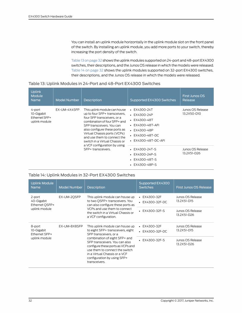
You can install an uplinkmodule horizontally in the uplinkmodule slot on the front panel
of the switch. By installing an uplink module, you addmore ports to your switch, thereby
increasing the port density of the switch.
Table 13onpage32shows theuplinkmodules supportedon24-port and48-portEX4300
switches, their descriptions, and the JunosOS release inwhich themodelswere released.
Table 14 on page 32 shows the uplink modules supported on 32-port EX4300 switches,
their descriptions, and the Junos OS release in which the models were released.
Table 13: Uplink Modules in 24-Port and 48-Port EX4300 Switches
First Junos OSReleaseSupported EX4300 SwitchesDescriptionModel Number
UplinkModuleName
Junos OS Release13.2X50-D10
• EX4300-24T
• EX4300-24P
• EX4300-48T
• EX4300-48T-AFI
• EX4300-48P
• EX4300-48T-DC
• EX4300-48T-DC-AFI
Thisuplinkmodulecanhouseup to four SFP+ transceivers,four SFP transceivers, or acombinationof fourSFP+andSFP transceivers. You canalso configure these ports asVirtual Chassis ports (VCPs)and use them to connect theswitch in a Virtual Chassis ora VCF configuration by usingSFP+ transceivers.
EX-UM-4X4SFP4-port10-GigabitEthernetSFP+uplinkmodule
Junos OS Release13.2X51-D26
• EX4300-24T-S
• EX4300-24P-S
• EX4300-48T-S
• EX4300-48P-S
Table 14: Uplink Modules in 32-Port EX4300 Switches
First Junos OS ReleaseSupported EX4300SwitchesDescriptionModel Number
Uplink ModuleName
Junos OS Release13.2X51-D15
• EX4300-32F
• EX4300-32F-DC
This uplink module can house upto two QSFP+ transceivers. Youcan also configure these ports asVCPs and use them to connectthe switch in a Virtual Chassis ora VCF configuration.
EX-UM-2QSFP2-port40-GigabitEthernet QSFP+uplink module
Junos OS Release13.2X51-D26
• EX4300-32F-S
Junos OS Release13.2X51-D15
• EX4300-32F
• EX4300-32F-DC
This uplink module can house upto eight SFP+ transceivers, eightSFP transceivers, or acombination of eight SFP+ andSFP transceivers. You can alsoconfigure theseportsasVCPsanduse them to connect the switchin a Virtual Chassis or a VCFconfiguration by using SFP+transceivers.
EX-UM-8X8SFP8-port10-GigabitEthernet SFP+uplink module
Junos OS Release13.2X51-D26
• EX4300-32F-S
Copyright © 2017, Juniper Networks, Inc.32
EX4300 Switch Hardware Guide
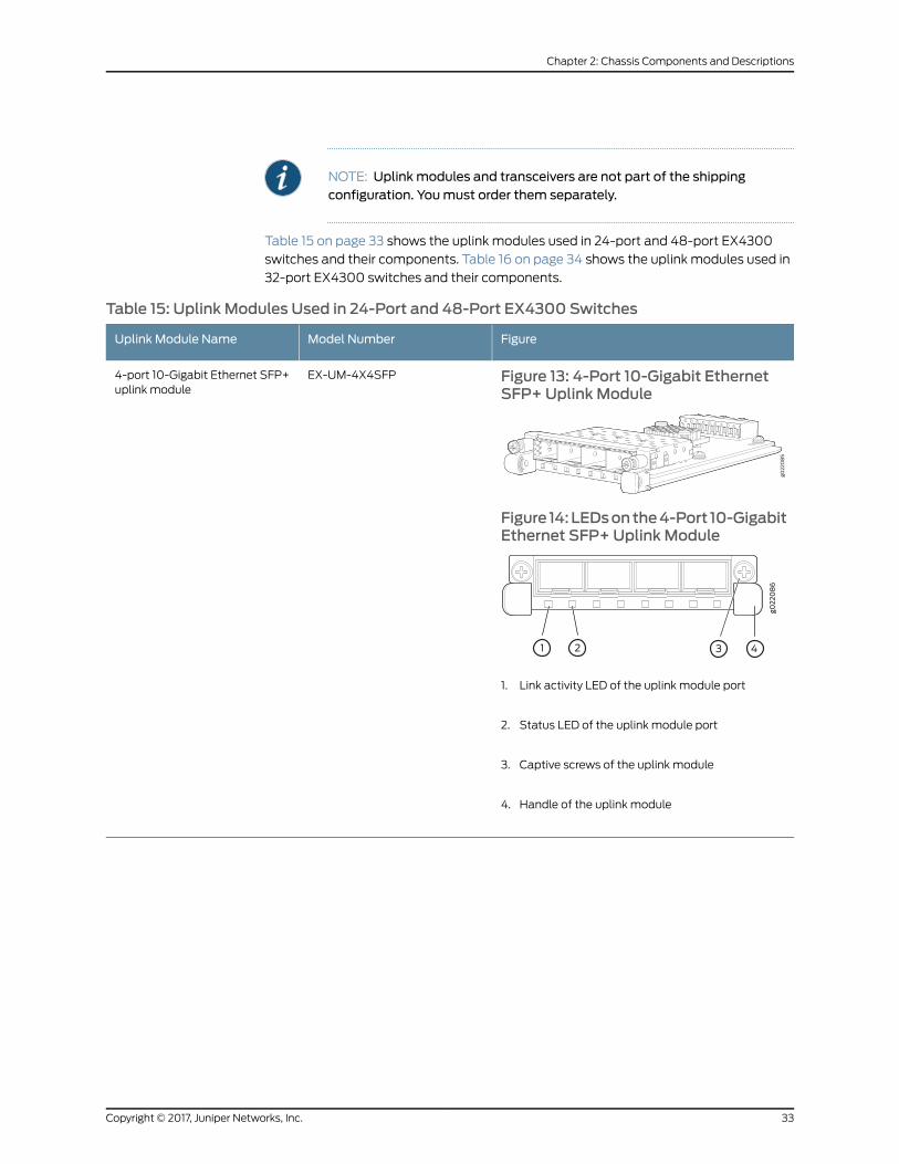
NOTE: Uplinkmodules and transceivers are not part of the shippingconfiguration. Youmust order them separately.
Table 15 on page 33 shows the uplink modules used in 24-port and 48-port EX4300
switches and their components. Table 16 on page 34 shows the uplink modules used in
32-port EX4300 switches and their components.
Table 15: Uplink Modules Used in 24-Port and 48-Port EX4300 Switches
FigureModel NumberUplink Module Name
Figure 13: 4-Port 10-Gigabit EthernetSFP+ Uplink Module
Figure 14:LEDsonthe4-Port 10-GigabitEthernet SFP+ Uplink Module
1. Link activity LED of the uplink module port
2. Status LED of the uplink module port
3. Captive screws of the uplink module
4. Handle of the uplink module
EX-UM-4X4SFP4-port 10-Gigabit Ethernet SFP+uplink module
33Copyright © 2017, Juniper Networks, Inc.
Chapter 2: Chassis Components and Descriptions
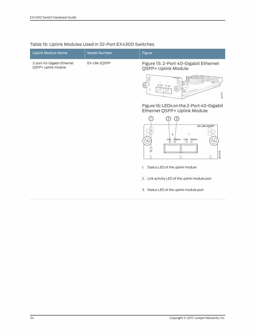
Table 16: Uplink Modules Used in 32-Port EX4300 Switches
FigureModel NumberUplink Module Name
Figure 15: 2-Port 40-Gigabit EthernetQSFP+Uplink Module
Figure 16:LEDsonthe2-Port40-GigabitEthernet QSFP+Uplink Module
1. Status LED of the uplink module
2. Link activity LED of the uplink module port
3. Status LED of the uplink module port
EX-UM-2QSFP2-port 40-Gigabit EthernetQSFP+ uplink module
Copyright © 2017, Juniper Networks, Inc.34
EX4300 Switch Hardware Guide
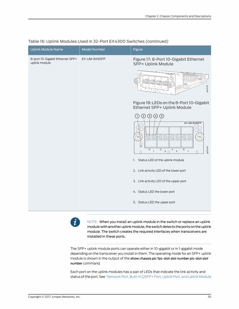
Table 16: Uplink Modules Used in 32-Port EX4300 Switches (continued)
FigureModel NumberUplink Module Name
Figure 17: 8-Port 10-Gigabit EthernetSFP+ Uplink Module
Figure 18:LEDsonthe8-Port 10-GigabitEthernet SFP+ Uplink Module
1. Status LED of the uplink module
2. Link activity LED of the lower port
3. Link activity LED of the upper port
4. Status LED the lower port
5. Status LED the upper port
EX-UM-8X8SFP8-port 10-Gigabit Ethernet SFP+uplink module
NOTE: When you install an uplink module in the switch or replace an uplinkmodulewithanotheruplinkmodule, theswitchdetects theportson theuplinkmodule. The switch creates the required interfaces when transceivers areinstalled in these ports.
The SFP+ uplink module ports can operate either in 10-gigabit or in 1-gigabit mode
depending on the transceiver you install in them. The operatingmode for an SFP+ uplink
module is shown in the output of the show chassis pic fpc-slot slot number pic-slot slot
number command.
Each port on the uplink modules has a pair of LEDs that indicate the link activity and
statusof theport. See “NetworkPort, Built-InQSFP+Port, UplinkPort, andUplinkModule
35Copyright © 2017, Juniper Networks, Inc.
Chapter 2: Chassis Components and Descriptions

Port LEDs on EX4300 Switches” on page 39 for details about the status and link activity
LEDs.
SFP+ uplink modules are shipped with dust covers installed in the ports. QSFP+ uplink
module is shipped with a dust cover installed in one of the ports.
RelatedDocumentation
Pluggable Transceivers Supported on EX4300 Switches on page 109•
• SFP+ Direct Attach Copper Cables for EX Series Switches on page 114
• Installing an Uplink Module in an EX4300 Switch on page 213
• EX Series Switches Interfaces Overview
Chassis Status LEDs on EX4300 Switches
An EX4300 switch has three chassis status LEDs (labeled ALM, SYS, andMST) on the
right of the LCD panel, next to the Menu and Enter buttons (see Figure 19 on page 36).
Figure 19: Chassis Status LEDs in an EX4300 Switch
3—1— LCD panel Menu buttonLCD panel
4—2— Chassis status LEDsLCD panel Enter button
Table 17 on page 37 describes the chassis status LEDs on an EX4300 switch, their colors
and states, and the status they indicate. You can view the colors of the three LEDs
remotely through the CLI by issuing the operational mode command show chassis led.
Copyright © 2017, Juniper Networks, Inc.36
EX4300 Switch Hardware Guide

Table 17: Chassis Status LEDs on an EX4300 Switch
State and DescriptionColorLED Label
There is no alarm or the switch is halted.UnlitALM (Alarm)
There is a major alarm.
NOTE: When you connect power to the switch, the Alarm (ALM) LED glows red.This behavior is normal. Plugging an active Ethernet cable into the management(MGMT) port on the switch completes the network link and turns off theALM LED.(See “Connecting a Device to a Network for Out-of-Band Management” onpage 165.)
Connecting the switch to a dedicatedmanagement console instead of a networkdoes not affect the ALM LED. The LED remains red until the switch is connectedto a network.
Red
There is a minor alarm.
NOTE: The Alarm (ALM) LED glows yellow if you commit a configuration tomakeit active on the switch and do not also create a rescue configuration to back it up.To save themost recently committed configuration as the rescue configuration,enter the operational mode command request system configuration rescue save.
Yellow
• On steadily—Junos OS for EX Series switches has been loaded on the switch.
• Blinking—The switch is booting.
• Off—The switch is powered off or is halted.
GreenSYS (System)
In a standalone EX4300 switch:
• On steadily—The switch is functioning normally as the master.
• Off—The switch is powered off or is halted.
In a Virtual Chassis configuration:
• On steadily—The switch is the master in the Virtual Chassis configuration.
• Blinking—The switch is the backup in the Virtual Chassis configuration.
• Off—The switch is a line card member in the Virtual Chassis configuration or ishalted.
GreenMST (Master)
Amajor alarm (red) indicates a critical error condition that requires immediate action.
A minor alarm (yellow) indicates a noncritical condition that requires monitoring or
maintenance. Aminor alarm that is left uncheckedmight cause interruption in service or
performance degradation.
All three LEDs can be lit simultaneously.
RelatedDocumentation
show chassis lcd•
• Chassis Component Alarm Conditions on EX4300 Switches on page 242
• Checking Active Alarms with the J-Web Interface on page 246
• Understanding Alarm Types and Severity Levels on EX Series Switches on page 241
37Copyright © 2017, Juniper Networks, Inc.
Chapter 2: Chassis Components and Descriptions

• EX4300 Switches Hardware Overview on page 3
Management Port LEDs on EX4300 Switches
Themanagement port, labeledMGMT, on the rear panel of an EX4300 switch, has two
LEDs that indicate link activity and status of themanagement port. Figure 20 on page 38
shows the location of Management port on a 24-port EX4300 switch.
Figure 20: LEDs on theManagement Port on a 24-port EX4300 Switch
2—1— Status LEDLink/Activity LED
Table 18 on page 38 describes the Link/Activity LED.
Table 18: Link/Activity LED on theManagement Port on an EX4300 Switch
State and DescriptionColorLED
• Blinking—The port and the link are active, and there is link activity.
• On steadily—The port and the link are active, but there is no link activity.
• Off—The port is not active.
GreenLink/Activity
Table 19 on page 38 describes the Status LED.
Table 19: Status LED on theManagement Port on an EX4300 Switch
State and DescriptionColorLED
Indicates the speed. The speed indicators are:
• Off—Link speed is 10 Mbps.
• Blinking—Link speed is 100 Mbps.
• On Steadily—Link speed is 1000Mbps.
GreenStatus
RelatedDocumentation
Connecting a Device to a Network for Out-of-Band Management on page 165•
• EX4300 Switches Hardware Overview on page 3
Copyright © 2017, Juniper Networks, Inc.38
EX4300 Switch Hardware Guide
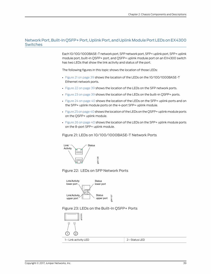
NetworkPort,Built-InQSFP+Port,UplinkPort,andUplinkModulePortLEDsonEX4300Switches
Each 10/100/1000BASE-Tnetworkport, SFPnetworkport, SFP+uplinkport, SFP+uplink
module port, built-in QSFP+ port, and QSFP+ uplink module port on an EX4300 switch
has two LEDs that show the link activity and status of the port.
The following figures in this topic shows the location of those LEDs:
• Figure 21 on page 39 shows the location of the LEDs on the 10/100/1000BASE-T
Ethernet network ports.
• Figure 22 on page 39 shows the location of the LEDs on the SFP network ports.
• Figure 23 on page 39 shows the location of the LEDs on the built-in QSFP+ ports.
• Figure 24 on page 40 shows the location of the LEDs on the SFP+ uplink ports and on
the SFP+ uplink module ports on the 4-port SFP+ uplink module.
• Figure25onpage40shows the locationof theLEDson theQSFP+uplinkmoduleports
on the QSFP+ uplink module.
• Figure 26 on page 40 shows the location of the LEDs on the SFP+ uplinkmodule ports
on the 8-port SFP+ uplink module.
Figure 21: LEDs on 10/100/1000BASE-T Network Ports
g041
128
Link/Activity
Status
Figure 22: LEDs on SFP Network Ports
g041
127
Link/Activitylower port
Link/Activityupper port
Statuslower port
Statusupper port
Figure 23: LEDs on the Built-In QSFP+ Ports
2—1— Status LEDLink activity LED
39Copyright © 2017, Juniper Networks, Inc.
Chapter 2: Chassis Components and Descriptions
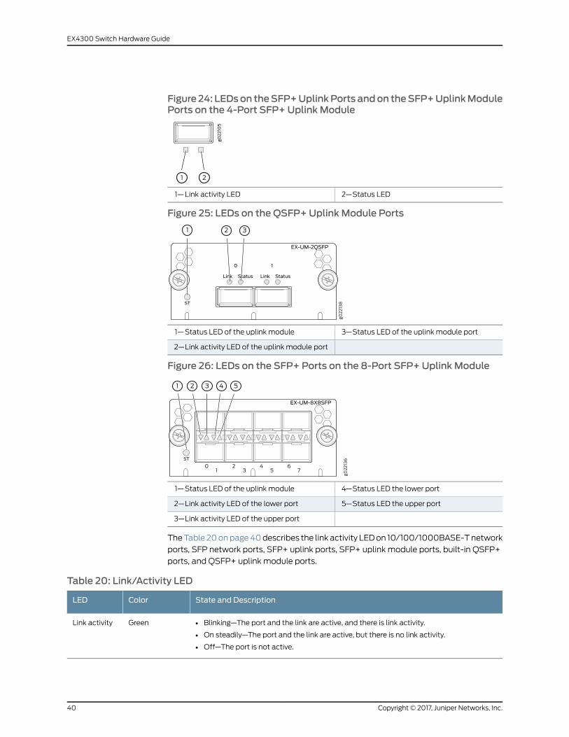
Figure 24: LEDson theSFP+UplinkPorts andon theSFP+UplinkModulePorts on the 4-Port SFP+ Uplink Module
2—1— Status LEDLink activity LED
Figure 25: LEDs on the QSFP+Uplink Module Ports
3—1— Status LED of the uplink module portStatus LED of the uplink module
2—Link activity LED of the uplink module port
Figure 26: LEDs on the SFP+ Ports on the 8-Port SFP+ Uplink Module
4—1— Status LED the lower portStatus LED of the uplink module
5—2— Status LED the upper portLink activity LED of the lower port
3—Link activity LED of the upper port
TheTable 20onpage40describes the link activity LEDon 10/100/1000BASE-Tnetwork
ports, SFP network ports, SFP+ uplink ports, SFP+ uplink module ports, built-in QSFP+
ports, and QSFP+ uplink module ports.
Table 20: Link/Activity LED
State and DescriptionColorLED
• Blinking—The port and the link are active, and there is link activity.
• On steadily—The port and the link are active, but there is no link activity.
• Off—The port is not active.
GreenLink activity
Copyright © 2017, Juniper Networks, Inc.40
EX4300 Switch Hardware Guide
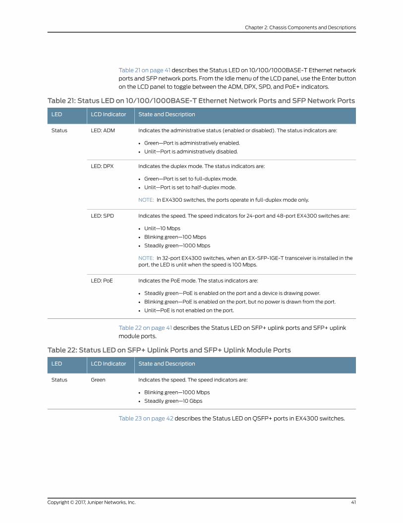
Table 21 on page 41 describes the Status LED on 10/100/1000BASE-T Ethernet network
ports and SFP network ports. From the Idlemenu of the LCD panel, use the Enter button
on the LCD panel to toggle between the ADM, DPX, SPD, and PoE+ indicators.
Table 21: Status LED on 10/100/1000BASE-T Ethernet Network Ports and SFP Network Ports
State and DescriptionLCD IndicatorLED
Indicates the administrative status (enabled or disabled). The status indicators are:
• Green—Port is administratively enabled.
• Unlit—Port is administratively disabled.
LED: ADMStatus
Indicates the duplex mode. The status indicators are:
• Green—Port is set to full-duplex mode.
• Unlit—Port is set to half-duplex mode.
NOTE: In EX4300 switches, the ports operate in full-duplex mode only.
LED: DPX
Indicates the speed. The speed indicators for 24-port and 48-port EX4300 switches are:
• Unlit—10 Mbps
• Blinking green—100Mbps
• Steadily green—1000Mbps
NOTE: In 32-port EX4300 switches, when an EX-SFP-1GE-T transceiver is installed in theport, the LED is unlit when the speed is 100 Mbps.
LED: SPD
Indicates the PoEmode. The status indicators are:
• Steadily green—PoE is enabled on the port and a device is drawing power.
• Blinking green—PoE is enabled on the port, but no power is drawn from the port.
• Unlit—PoE is not enabled on the port.
LED: PoE
Table 22 on page 41 describes the Status LED on SFP+ uplink ports and SFP+ uplink
module ports.
Table 22: Status LED on SFP+ Uplink Ports and SFP+ Uplink Module Ports
State and DescriptionLCD IndicatorLED
Indicates the speed. The speed indicators are:
• Blinking green—1000Mbps
• Steadily green—10 Gbps
GreenStatus
Table 23 on page 42 describes the Status LED on QSFP+ ports in EX4300 switches.
41Copyright © 2017, Juniper Networks, Inc.
Chapter 2: Chassis Components and Descriptions

Table 23: Status LED on QSFP+ Ports
State and DescriptionLCD IndicatorLED
Indicates the status. The status indicators are:
• Unlit—40-Gigabit port is down.
• Steadily green—40-Gigabit port is up.
GreenStatus
RelatedDocumentation
• Uplink Modules in EX4300 Switches on page 31
• EX4300 Switches Hardware Overview on page 3
Copyright © 2017, Juniper Networks, Inc.42
EX4300 Switch Hardware Guide

CHAPTER 3
Cooling System and Airflow
• Cooling System and Airflow in an EX4300 Switch on page 43
Cooling System and Airflow in an EX4300 Switch
The cooling system in an EX4300 switch consists of two fanmodules and a single fan
in each power supply. EX4300 switches provide back-to-front airflow (air enters through
the back of the switch), indicated by the labelAIR IN (AFI), or front-to-back (air exhausts
through the back of the switch), indicated by the label AIR OUT (AFO)—depending on
the fanmodules and power supplies installed in the switch.
This topic describes:
• Fan Modules on page 43
• Airflow Direction in EX4300 Switch Models on page 44
• Front-to-Back Airflow on page 45
• Back-to-Front Airflow on page 46
• Do Not Mix AIR IN (AFI) and AIR OUT (AFO) Components in the Switch on page 47
• Positioning the Switch on page 47
• Fan Module Status on page 48
FanModules
In the EX4300 switches the fanmodules are hot-insertable and hot-removable
field-replaceable units (FRUs).
All the EX4300 switches, except EX4300-24T-S, EX4300-24P-S, EX4300-32F-S,
EX4300-48T-S, and EX4300-48P-S switches are shipped with two fanmodules
pre-installed in the rear panel of the switch. EX4300-24T-S, EX4300-24P-S,
EX4300-32F-S, EX4300-48T-S, and EX4300-48P-S switches are not shipped with
pre-installed fanmodules; youmust order them separately. Each switch can
accommodate two fanmodules in the fanmodule slots on the rear panel of the switch.
The fanmodule slots are numbered 0 and 1 and each slot has a fan icon next to it.
Figure 27 on page 44 shows the fanmodule used in an EX4300 switch:
43Copyright © 2017, Juniper Networks, Inc.
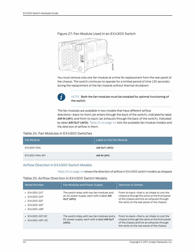
Figure 27: FanModule Used in an EX4300 Switch
Youmust remove only one fanmodule at a time for replacement from the rear panel of
the chassis. The switch continues to operate for a limited period of time (30 seconds)
during the replacement of the fanmodule without thermal shutdown.
NOTE: Both the fanmodulesmust be installed for optimal functioning ofthe switch.
The fanmodules are available in twomodels that have different airflow
directions—back-to-front (air enters through the back of the switch), indicated by label
AIR IN (AFI), and front-to-back (air exhausts through the back of the switch), indicated
by label AIR OUT (AFO). Table 24 on page 44 lists the available fanmodule models and
the direction of airflow in them.
Table 24: FanModules in EX4300 Switches
Label on the FanModuleFanModule
AIR OUT (AFO)EX4300-FAN
AIR IN (AFI)EX4300-FAN-AFI
Airflow Direction in EX4300 SwitchModels
Table 25 on page 44 shows the direction of airflow in EX4300 switchmodels as shipped.
Table 25: Airflow Direction in EX4300 SwitchModels
Direction of AirflowFanModules and Power SupplyModel Number
Front-to-back—that is, air intake to cool thechassis is through theventson the frontpanelof the chassis and hot air exhausts throughthe vents on the rear panel of the chassis.
The switch ships with two fanmodules andan AC power supply, each with a label AIROUT (AFO).
• EX4300-24T
• EX4300-24P
• EX4300-32F
• EX4300-48T
• EX4300-48P
Front-to-back—that is, air intake to cool thechassis is through theventson the frontpanelof the chassis and hot air exhausts throughthe vents on the rear panel of the chassis.
The switch ships with two fanmodules and aDC power supply, each with a label AIR OUT(AFO).
• EX4300-32F-DC
• EX4300-48T-DC
Copyright © 2017, Juniper Networks, Inc.44
EX4300 Switch Hardware Guide
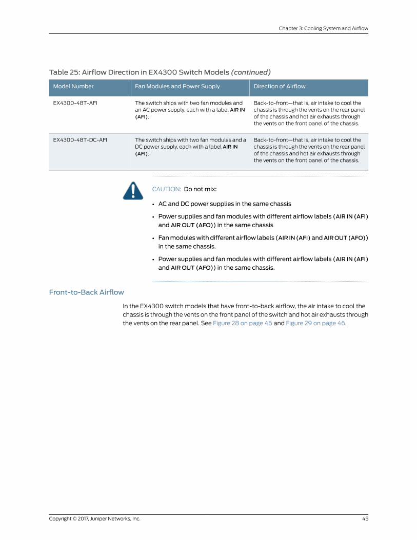
Table 25: Airflow Direction in EX4300 SwitchModels (continued)
Direction of AirflowFanModules and Power SupplyModel Number
Back-to-front—that is, air intake to cool thechassis is through the vents on the rear panelof the chassis and hot air exhausts throughthe vents on the front panel of the chassis.
The switch ships with two fanmodules andan AC power supply, each with a label AIR IN(AFI).
EX4300-48T-AFI
Back-to-front—that is, air intake to cool thechassis is through the vents on the rear panelof the chassis and hot air exhausts throughthe vents on the front panel of the chassis.
The switch ships with two fanmodules and aDC power supply, each with a label AIR IN(AFI).
EX4300-48T-DC-AFI
CAUTION: Do notmix:
• AC and DC power supplies in the same chassis
• Power supplies and fanmodules with different airflow labels (AIR IN (AFI)
and AIR OUT (AFO)) in the same chassis
• Fanmoduleswith different airflow labels (AIR IN (AFI)andAIROUT(AFO))
in the same chassis.
• Power supplies and fanmodules with different airflow labels (AIR IN (AFI)
and AIR OUT (AFO)) in the same chassis.
Front-to-Back Airflow
In the EX4300 switch models that have front-to-back airflow, the air intake to cool the
chassis is through the vents on the front panel of the switch and hot air exhausts through
the vents on the rear panel. See Figure 28 on page 46 and Figure 29 on page 46.
45Copyright © 2017, Juniper Networks, Inc.
Chapter 3: Cooling System and Airflow
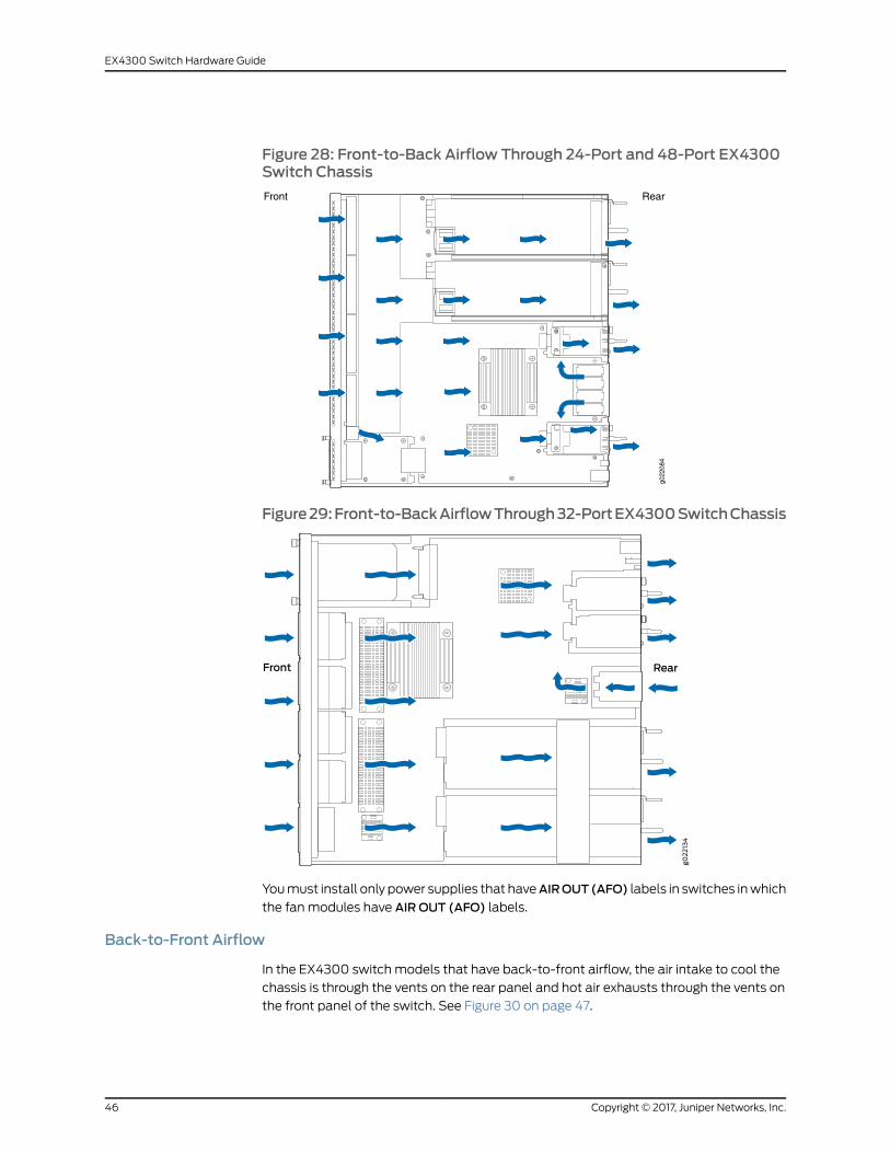
Figure 28: Front-to-Back Airflow Through 24-Port and 48-Port EX4300Switch Chassis
Front Rear
g022
084
Figure29:Front-to-BackAirflowThrough32-PortEX4300SwitchChassis
Youmust install only power supplies that haveAIROUT(AFO) labels in switches inwhich
the fanmodules have AIR OUT (AFO) labels.
Back-to-Front Airflow
In the EX4300 switch models that have back-to-front airflow, the air intake to cool the
chassis is through the vents on the rear panel and hot air exhausts through the vents on
the front panel of the switch. See Figure 30 on page 47.
Copyright © 2017, Juniper Networks, Inc.46
EX4300 Switch Hardware Guide

Figure30:Back-to-FrontAirflowThroughthe24-Portand48-PortEX4300Switch Chassis
Youmust install only power supplies that have AIR IN (AFI) labels in switches in which
the fanmodules have AIR IN (AFI) labels.
DoNotMix AIR IN (AFI) and AIR OUT (AFO) Components in the Switch
Do not mix power supplies and fanmodules with different airflow labels (AIR IN (AFI)
and AIROUT (AFO)) in the same chassis. If the fanmodules have AIR IN (AFI) labels, the
power suppliesmustalsohaveAIR IN(AFI) labels; if the fanmoduleshaveAIROUT(AFO)
labels, the power supplies must also have AIR OUT (AFO) labels.
The labels on thepower supplies and fanmodules shouldmatch the labels on the switch
chassis.
Mixing components with AIR IN (AFI) and AIR OUT (AFO) labels in the same chassis
hampers the performance of the cooling system of the switch and leads to overheating
of the chassis.
CAUTION: The system raises an alarm if a fanmodule fails or if the ambienttemperature inside the chassis rises above the acceptable range. If thetemperature inside the chassis rises above the threshold temperature, thesystem shuts down automatically.
Positioning the Switch
In front-to-back airflow, indicated by the label AIR OUT (AFO) on the fanmodules and
power supplies, hot air exhausts through the vents on the rear panel of the switch. In
back-to-front airflow, indicated by the label AIR IN (AFI) on the fanmodules and power
supplies, hot air exhausts through the vents on the front panel of the switch.
47Copyright © 2017, Juniper Networks, Inc.
Chapter 3: Cooling System and Airflow
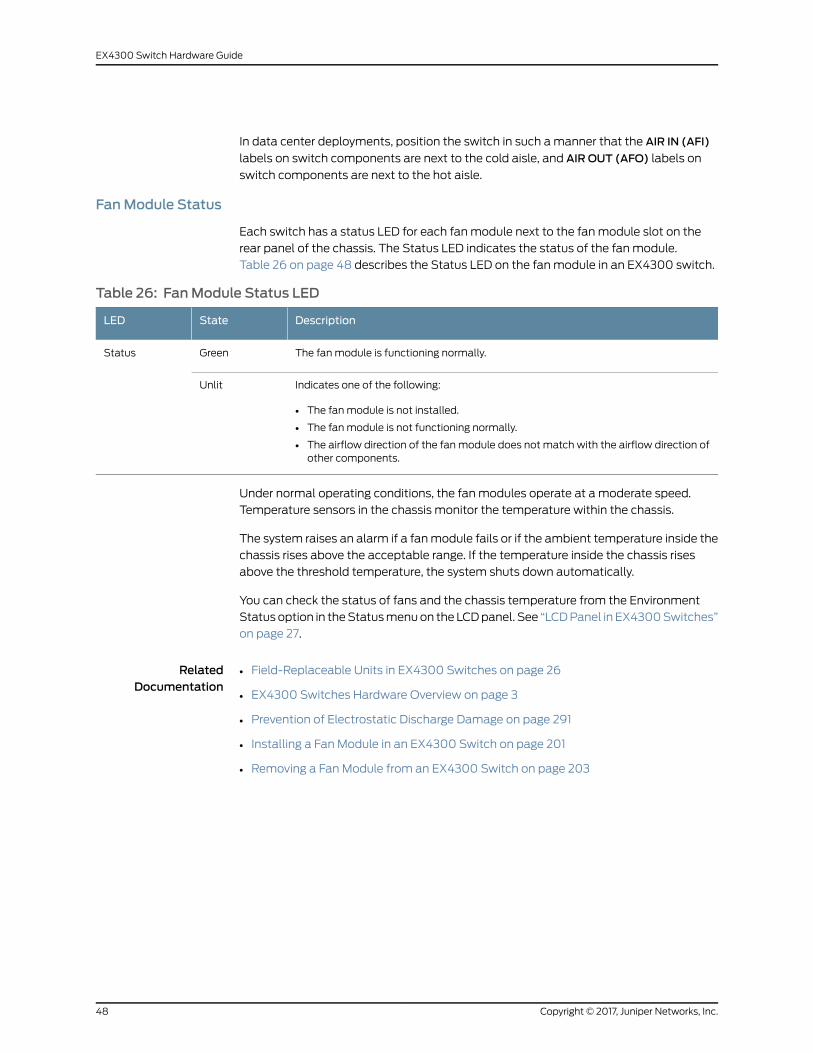
In data center deployments, position the switch in such amanner that the AIR IN (AFI)
labels on switch components are next to the cold aisle, and AIR OUT (AFO) labels on
switch components are next to the hot aisle.
FanModule Status
Each switch has a status LED for each fanmodule next to the fanmodule slot on the
rear panel of the chassis. The Status LED indicates the status of the fanmodule.
Table 26 on page 48 describes the Status LED on the fanmodule in an EX4300 switch.
Table 26: FanModule Status LED
DescriptionStateLED
The fanmodule is functioning normally.GreenStatus
Indicates one of the following:
• The fanmodule is not installed.
• The fanmodule is not functioning normally.
• The airflow direction of the fanmodule does not match with the airflow direction ofother components.
Unlit
Under normal operating conditions, the fanmodules operate at a moderate speed.
Temperature sensors in the chassis monitor the temperature within the chassis.
The system raises an alarm if a fanmodule fails or if the ambient temperature inside the
chassis rises above the acceptable range. If the temperature inside the chassis rises
above the threshold temperature, the system shuts down automatically.
You can check the status of fans and the chassis temperature from the Environment
Status option in theStatusmenuon the LCDpanel. See “LCDPanel in EX4300Switches”
on page 27.
RelatedDocumentation
• Field-Replaceable Units in EX4300 Switches on page 26
• EX4300 Switches Hardware Overview on page 3
• Prevention of Electrostatic Discharge Damage on page 291
• Installing a Fan Module in an EX4300 Switch on page 201
• Removing a Fan Module from an EX4300 Switch on page 203
Copyright © 2017, Juniper Networks, Inc.48
EX4300 Switch Hardware Guide

CHAPTER 4
Power Supplies
• AC Power Supply in EX4300 Switches on page 49
• AC Power Supply LEDs in EX4300 Switches on page 56
• DC Power Supply in EX4300 Switches on page 57
• DC Power Supply LEDs in EX4300 Switches on page 62
AC Power Supply in EX4300 Switches
The AC power supply in EX4300 switches is a hot-insertable and hot-removable
field-replaceable unit (FRU): You can install it without powering off the switch or
disrupting the switching function.
All the EX4300 switches that are powered by ACpower supplies except EX4300-24T-S,
EX4300-24P-S, EX4300-32F-S, EX4300-48T-S, and EX4300-48P-S switches are
shipped with one AC power supply pre-installed in the rear panel of the switches.
EX4300-24T-S, EX4300-24P-S, EX4300-32F-S, EX4300-48T-S, and EX4300-48P-S
switches are not shipped with pre-installed power supplies; youmust order them
separately.
This topic describes the AC power supplies.
CAUTION: Do notmix:
• AC and DC power supplies in the same chassis
• Power supplies with different airflow labels (AIR IN (AFI) and AIR OUT
(AFO)) in the same chassis.
• Fanmoduleswith different airflow labels (AIR IN (AFI)andAIROUT(AFO))
in the same chassis.
• Power supplies and fanmodules with different airflow labels (AIR IN (AFI)
and AIR OUT (AFO)) in the same chassis.
This topic includes:
• Characteristics of an AC Power Supply on page 50
• AC Power Supply Airflow on page 51
49Copyright © 2017, Juniper Networks, Inc.
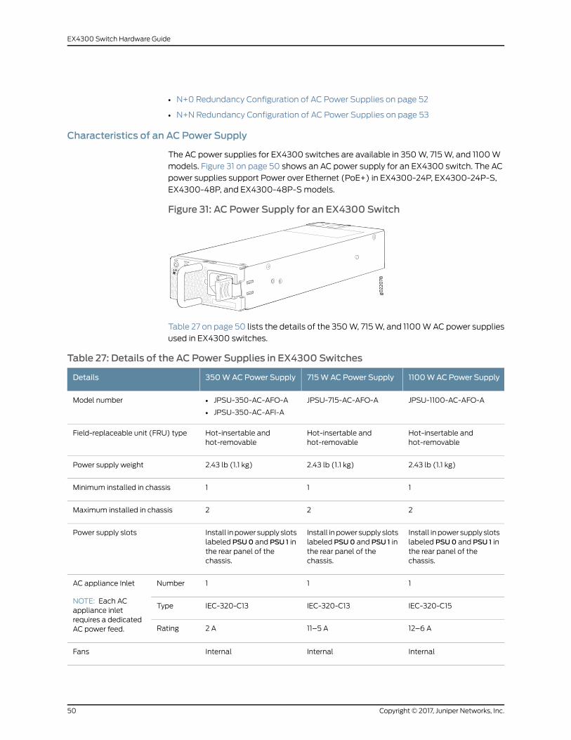
• N+0 Redundancy Configuration of AC Power Supplies on page 52
• N+N Redundancy Configuration of AC Power Supplies on page 53
Characteristics of an AC Power Supply
The AC power supplies for EX4300 switches are available in 350W, 715W, and 1100W
models. Figure 31 on page 50 shows an AC power supply for an EX4300 switch. The AC
power supplies support Power over Ethernet (PoE+) in EX4300-24P, EX4300-24P-S,
EX4300-48P, and EX4300-48P-Smodels.
Figure 31: AC Power Supply for an EX4300 Switch
Table 27 on page 50 lists the details of the 350W, 715W, and 1100WAC power supplies
used in EX4300 switches.
Table 27: Details of the AC Power Supplies in EX4300 Switches
1100WACPower Supply715WAC Power Supply350WAC Power SupplyDetails
JPSU-1100-AC-AFO-AJPSU-715-AC-AFO-A• JPSU-350-AC-AFO-A
• JPSU-350-AC-AFI-A
Model number
Hot-insertable andhot-removable
Hot-insertable andhot-removable
Hot-insertable andhot-removable
Field-replaceable unit (FRU) type
2.43 lb (1.1 kg)2.43 lb (1.1 kg)2.43 lb (1.1 kg)Power supply weight
111Minimum installed in chassis
222Maximum installed in chassis
Install inpower supply slotslabeled PSU0 and PSU 1 inthe rear panel of thechassis.
Install inpower supply slotslabeled PSU0 and PSU 1 inthe rear panel of thechassis.
Install inpower supply slotslabeled PSU0 and PSU 1 inthe rear panel of thechassis.
Power supply slots
111NumberAC appliance Inlet
NOTE: Each ACappliance inletrequires a dedicatedAC power feed.
IEC-320-C15IEC-320-C13IEC-320-C13Type
12–6 A11–5 A2 ARating
InternalInternalInternalFans
Copyright © 2017, Juniper Networks, Inc.50
EX4300 Switch Hardware Guide

Table 27: Details of the AC Power Supplies in EX4300 Switches (continued)
1100WACPower Supply715WAC Power Supply350WAC Power SupplyDetails
Front-to-back, indicatedbylabel AIR OUT (AFO)
Front-to-back, indicatedbylabel AIR OUT (AFO)
• Front-to-back, indicatedby label AIR OUT (AFO)
• Back-to-front, indicatedby label AIR IN (AFI)
Airflow
111AC power cord retainer
IN OK andOUTOKINOK andOUTOKINOK andOUTOKPower supply status LEDs
115–240 VAC100–240 VAC100–240 VACOperating range
Toprevent electrical injurywhile installingor removingACpower supplies, carefully follow
instructions in “Installing an AC Power Supply in an EX4300 Switch” on page 205 and
“Removing an AC Power Supply from an EX4300 Switch” on page 207.
AC Power Supply Airflow
Each power supply has its own fan and is cooled by its own internal cooling system.
Each power supply has a label AIR OUT (AFO) or AIR IN (AFI) on the faceplate of the
power supply that indicates the direction of airflow in the power supply.
Table 28 on page 51 lists the AC power supply models and the direction of airflow in
them.
Table 28: Airflow Direction in AC Power Supply Models for EX4300 Switches
Direction of AirflowLabel on PowerSupplyModel
Front-to-back—that is, air intake to cool the chassis is through the ventson the front panel of the chassis and hot air exhausts through the ventson the rear panel of the chassis.
AIR OUT (AFO)JPSU-350-AC-AFO-A
Back-to-front—that is, air intake to cool the chassis is through the ventson the rear panel of the chassis and hot air exhausts through the vents onthe front panel of the chassis.
AIR IN (AFI)JPSU-350-AC-AFI-A
Front-to-back—that is, air intake to cool the chassis is through the ventson the front panel of the chassis and hot air exhausts through the ventson the rear panel of the chassis.
AIR OUT (AFO)JPSU-715-AC-AFO-A
Front-to-back—that is, air intake to cool the chassis is through the ventson the front panel of the chassis and hot air exhausts through the ventson the rear panel of the chassis.
AIR OUT (AFO)JPSU-1100-AC-AFO-A
51Copyright © 2017, Juniper Networks, Inc.
Chapter 4: Power Supplies
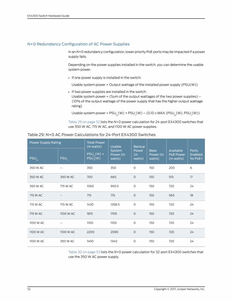
N+0 Redundancy Configuration of AC Power Supplies
In anN+0 redundancy configuration, lower priority PoE portsmay be impacted if a power
supply fails.
Depending on the power supplies installed in the switch, you can determine the usable
system power.
• If one power supply is installed in the switch:
Usable system power = Output wattage of the installed power supply (PSU(W))
• If two power supplies are installed in the switch:
Usable system power = (Sum of the output wattages of the two power supplies) –
(10% of the output wattage of the power supply that has the higher output wattage
rating)
Usable system power = PSU0(W) + PSU
1(W) – (0.10 x MAX (PSU
0(W), PSU
1(W))
Table 29 on page 52 lists the N+0 power calculation for 24-port EX4300 switches that
use 350WAC, 715W AC, and 1100WAC power supplies.
Table 29: N+0 AC Power Calculations for 24-Port EX4300 Switches
PortsEnabledfor PoE+
AvailablePoE Power(in watts)
BasePower (inwatts)
BackupPower(inwatts)
UsableSystemPower (inwatts)
Total Power(in watts)
PSU0(W) +
PSU1(W)
Power Supply Rating
PSU1
PSU0
62001500350350–350WAC
175151500665700350WAC350WAC
247201500993.51065715W AC350WAC
185651500715715–715W AC
2472015001358.51430715W AC715W AC
247201500170518151100WAC715W AC
24720150011001100–1100WAC
247201500209022001100WAC1100WAC
24720150013401450350WAC1100WAC
Table 30 on page 53 lists the N+0 power calculation for 32-port EX4300 switches that
use the 350WAC power supply.
Copyright © 2017, Juniper Networks, Inc.52
EX4300 Switch Hardware Guide
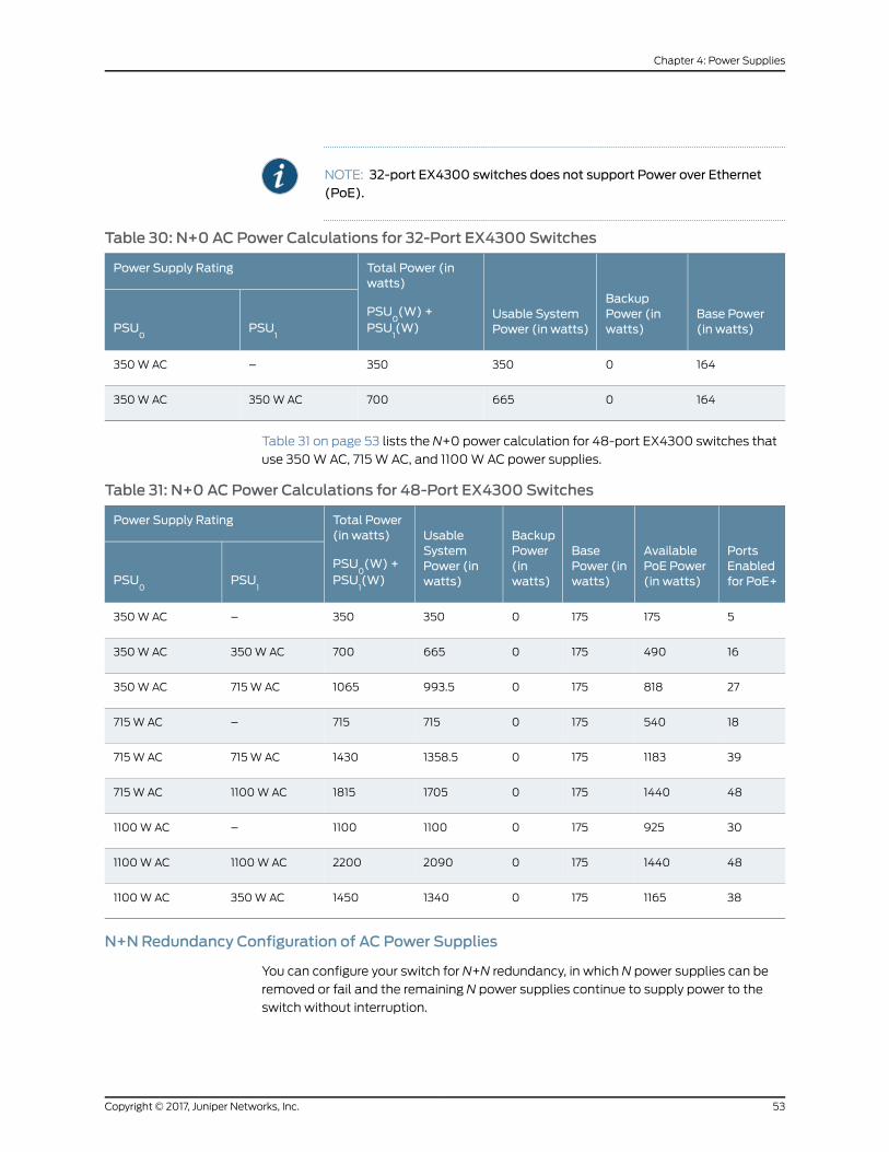
NOTE: 32-port EX4300 switches does not support Power over Ethernet(PoE).
Table 30: N+0 AC Power Calculations for 32-Port EX4300 Switches
Base Power(in watts)
BackupPower (inwatts)
Usable SystemPower (in watts)
Total Power (inwatts)
PSU0(W) +
PSU1(W)
Power Supply Rating
PSU1
PSU0
1640350350–350WAC
1640665700350WAC350WAC
Table 31 on page 53 lists the N+0 power calculation for 48-port EX4300 switches that
use 350WAC, 715W AC, and 1100WAC power supplies.
Table 31: N+0 AC Power Calculations for 48-Port EX4300 Switches
PortsEnabledfor PoE+
AvailablePoE Power(in watts)
BasePower (inwatts)
BackupPower(inwatts)
UsableSystemPower (inwatts)
Total Power(in watts)
PSU0(W) +
PSU1(W)
Power Supply Rating
PSU1
PSU0
51751750350350–350WAC
164901750665700350WAC350WAC
278181750993.51065715W AC350WAC
185401750715715–715W AC
39118317501358.51430715W AC715W AC
4814401750170518151100WAC715W AC
30925175011001100–1100WAC
4814401750209022001100WAC1100WAC
381165175013401450350WAC1100WAC
N+NRedundancy Configuration of AC Power Supplies
You can configure your switch for N+N redundancy, in which N power supplies can be
removed or fail and the remaining N power supplies continue to supply power to the
switch without interruption.
53Copyright © 2017, Juniper Networks, Inc.
Chapter 4: Power Supplies

You can configure the power management software to manage switch power for N+N
redundancy. When you configure power management for N+N redundancy, half of the
total power available (N) is held as reserve power while the other half (N) is available
for immediate consumption. If the switch configuration changes and requires additional
power, then additional power is drawn from the reserve power, and the switch no longer
has N+N power supply redundancy. This condition raises a minor alarm. If the condition
is not corrected within 5 minutes, then amajor alarm is issued.
For more information about how power management allocates power to chassis
components when power is insufficient, see Understanding Power Management on EX
Series Switches.
Depending on the power supplies installed in the switch, you can determine the usable
system power.
• If one power supply is installed in the switch:
• Usable system power = Output wattage of the installed power supply (PSU(W))
• Backup power available = 0W
Aminor alarm is raised as the switch has no N+N power supply redundancy.
• If two power supplies are installed in the switch:
• Usable system power = (Output wattage of the power supply that has the lower
outputwattage)– (5%of theoutputwattageof thepower supply that has the lower
output wattage rating)
Usablesystempower=MIN(PSU0(W),PSU
1(W))–(0.05xMIN(PSU
0(W),PSU
1(W))
• Backup power available = (Output wattage of the power supply that has the lower
outputwattage)– (5%of theoutputwattageof thepower supply that has the lower
output wattage rating)
Backup power available = MIN(PSU0(W), PSU
1(W)) – (0.05 x MIN (PSU
0(W),
PSU1(W))
Table 32 on page 54 lists the N+N power calculation for 24-port EX4300 switches that
use 350W, 715W AC, and 1100WAC power supplies.
Table 32: N+N AC Power Calculations for 24-Port EX4300 Switches
PortsenabledforPoE+
AvailablePoE Power(in watts)
BasePower (inwatts)
BackupPower (inwatts)
UsableSystemPower (inwatts)
TotalPower (inwatts)
Power Supply Rating
PSU1
PSU0
62001500350350–350WAC
6200150350350700350WAC350WAC
62001503503501065715W AC350WAC
185651500715715–715W AC
Copyright © 2017, Juniper Networks, Inc.54
EX4300 Switch Hardware Guide
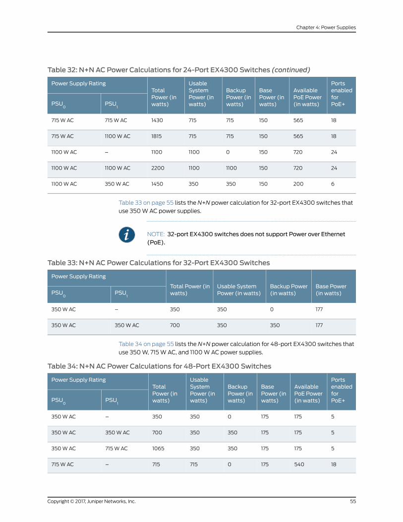
Table 32: N+N AC Power Calculations for 24-Port EX4300 Switches (continued)
PortsenabledforPoE+
AvailablePoE Power(in watts)
BasePower (inwatts)
BackupPower (inwatts)
UsableSystemPower (inwatts)
TotalPower (inwatts)
Power Supply Rating
PSU1
PSU0
185651507157151430715W AC715W AC
1856515071571518151100WAC715W AC
24720150011001100–1100WAC
247201501100110022001100WAC1100WAC
62001503503501450350WAC1100WAC
Table 33 on page 55 lists the N+N power calculation for 32-port EX4300 switches that
use 350WAC power supplies.
NOTE: 32-port EX4300 switches does not support Power over Ethernet(PoE).
Table 33: N+N AC Power Calculations for 32-Port EX4300 Switches
Base Power(in watts)
Backup Power(in watts)
Usable SystemPower (in watts)
Total Power (inwatts)
Power Supply Rating
PSU1
PSU0
1770350350–350WAC
177350350700350WAC350WAC
Table 34 on page 55 lists the N+N power calculation for 48-port EX4300 switches that
use 350W, 715W AC, and 1100WAC power supplies.
Table 34: N+N AC Power Calculations for 48-Port EX4300 Switches
PortsenabledforPoE+
AvailablePoE Power(in watts)
BasePower (inwatts)
BackupPower (inwatts)
UsableSystemPower (inwatts)
TotalPower (inwatts)
Power Supply Rating
PSU1
PSU0
51751750350350–350WAC
5175175350350700350WAC350WAC
51751753503501065715W AC350WAC
185401750715715–715W AC
55Copyright © 2017, Juniper Networks, Inc.
Chapter 4: Power Supplies

Table 34: N+N AC Power Calculations for 48-Port EX4300 Switches (continued)
PortsenabledforPoE+
AvailablePoE Power(in watts)
BasePower (inwatts)
BackupPower (inwatts)
UsableSystemPower (inwatts)
TotalPower (inwatts)
Power Supply Rating
PSU1
PSU0
185401757157151430715W AC715W AC
1854017571571518151100WAC715W AC
30925175011001100–1100WAC
309251751100110022001100WAC1100WAC
51751753503501450350WAC1100WAC
RelatedDocumentation
AC Power Supply LEDs in EX4300 Switches on page 56•
• AC Power Supply Specifications for EX4300 Switches on page 99
• Installing an AC Power Supply in an EX4300 Switch on page 205
AC Power Supply LEDs in EX4300 Switches
Figure32onpage56shows the locationof theLEDsonanACpower supply foranEX4300
switch.
Figure 32: AC Power Supply LEDs in an EX4300 Switch
1 2
2—1— OUTOK LEDIN OK LED
Table 35 on page 57 describes the AC power supply LEDs.
Copyright © 2017, Juniper Networks, Inc.56
EX4300 Switch Hardware Guide
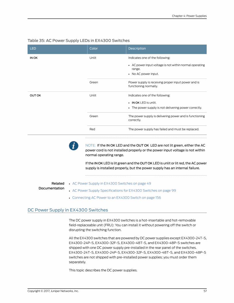
Table 35: AC Power Supply LEDs in EX4300 Switches
DescriptionColorLED
Indicates one of the following:
• ACpower input voltage is notwithinnormal operatingrange.
• No AC power input.
UnlitIN OK
Power supply is receiving proper input power and isfunctioning normally.
Green
Indicates one of the following:
• IN OK LED is unlit.
• The power supply is not delivering power correctly.
UnlitOUTOK
The power supply is delivering power and is functioningcorrectly.
Green
The power supply has failed andmust be replaced.Red
NOTE: If the IN OK LED and theOUTOK LED are not lit green, either the AC
power cord is not installed properly or the power input voltage is not withinnormal operating range.
If the INOK LED is lit greenand theOUTOK LED is unlit or lit red, theACpower
supply is installed properly, but the power supply has an internal failure.
RelatedDocumentation
AC Power Supply in EX4300 Switches on page 49•
• AC Power Supply Specifications for EX4300 Switches on page 99
• Connecting AC Power to an EX4300 Switch on page 156
DC Power Supply in EX4300 Switches
The DC power supply in EX4300 switches is a hot-insertable and hot-removable
field-replaceable unit (FRU): You can install it without powering off the switch or
disrupting the switching function.
All the EX4300 switches that are powered byDCpower supplies except EX4300-24T-S,
EX4300-24P-S, EX4300-32F-S, EX4300-48T-S, and EX4300-48P-S switches are
shipped with one DC power supply pre-installed in the rear panel of the switches.
EX4300-24T-S, EX4300-24P-S, EX4300-32F-S, EX4300-48T-S, and EX4300-48P-S
switches are not shipped with pre-installed power supplies; youmust order them
separately.
This topic describes the DC power supplies.
57Copyright © 2017, Juniper Networks, Inc.
Chapter 4: Power Supplies

CAUTION: Do notmix:
• AC and DC power supplies in the same chassis
• Power supplies with different airflow labels (AIR IN (AFI) and AIR OUT
(AFO)) in the same chassis.
• Fanmoduleswith different airflow labels (AIR IN (AFI)andAIROUT(AFO))
in the same chassis.
• Power supplies and fanmodules with different airflow labels (AIR IN (AFI)
and AIR OUT (AFO)) in the same chassis.
This topic includes:
• Characteristics of a DC Power Supply on page 58
• DC Power Supply Airflow on page 59
• N+0 Redundancy Configuration of DC Power Supplies on page 60
• N+N Redundancy Configuration of DC Power Supplies on page 60
Characteristics of a DC Power Supply
EX4300 switches support 550WDC power supply (see Figure 33 on page 58). The DC
power supplies support Power over Ethernet (PoE+) in EX4300-24P, EX4300-24P-S,
EX4300-48P, and EX4300-48P-Smodels.
Figure 33: DC Power Supply for an EX4300 Switch
You can install up to two DC power supplies in an EX4300 switch. Power supplies are
installed in thepower supply slots labeledPSU0andPSU1 in the rear panel of thechassis.
Table 36 on page 58 lists the details of the 550WDC power supplies used in EX4300
switches.
Table 36: Details of the DC Power Supplies in EX4300 Switches
550WDC Power SupplyDetails
• JPSU-550-DC-AFO-A
• JPSU-550-DC-AFI-A
Model number
Hot-insertable and hot-removableField-replaceable unit (FRU) type
Copyright © 2017, Juniper Networks, Inc.58
EX4300 Switch Hardware Guide
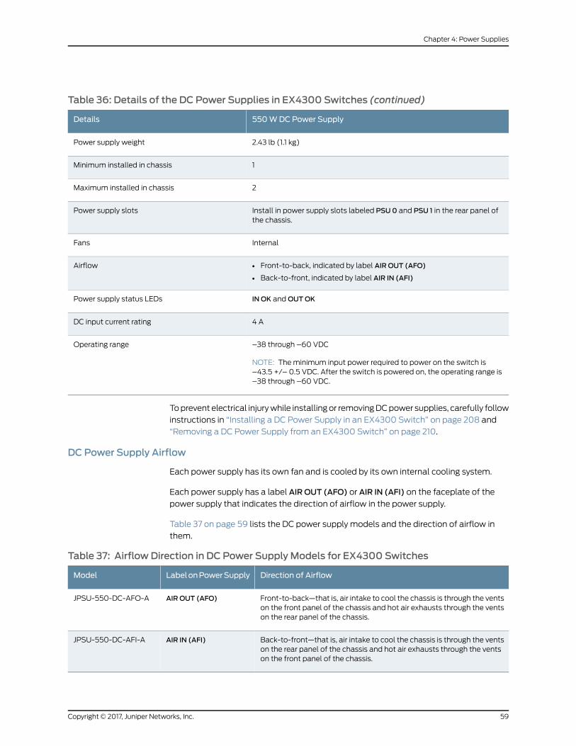
Table 36: Details of the DC Power Supplies in EX4300 Switches (continued)
550WDC Power SupplyDetails
2.43 lb (1.1 kg)Power supply weight
1Minimum installed in chassis
2Maximum installed in chassis
Install in power supply slots labeled PSU0 and PSU 1 in the rear panel ofthe chassis.
Power supply slots
InternalFans
• Front-to-back, indicated by label AIR OUT (AFO)
• Back-to-front, indicated by label AIR IN (AFI)
Airflow
IN OK andOUTOKPower supply status LEDs
4 ADC input current rating
–38 through –60 VDC
NOTE: Theminimum input power required to power on the switch is–43.5 +/– 0.5 VDC. After the switch is powered on, the operating range is–38 through –60 VDC.
Operating range
Toprevent electrical injurywhile installingor removingDCpower supplies, carefully follow
instructions in “Installing a DC Power Supply in an EX4300 Switch” on page 208 and
“Removing a DC Power Supply from an EX4300 Switch” on page 210.
DC Power Supply Airflow
Each power supply has its own fan and is cooled by its own internal cooling system.
Each power supply has a label AIR OUT (AFO) or AIR IN (AFI) on the faceplate of the
power supply that indicates the direction of airflow in the power supply.
Table 37 on page 59 lists the DC power supply models and the direction of airflow in
them.
Table 37: Airflow Direction in DC Power Supply Models for EX4300 Switches
Direction of AirflowLabelonPowerSupplyModel
Front-to-back—that is, air intake to cool the chassis is through the ventson the front panel of the chassis and hot air exhausts through the ventson the rear panel of the chassis.
AIR OUT (AFO)JPSU-550-DC-AFO-A
Back-to-front—that is, air intake to cool the chassis is through the ventson the rear panel of the chassis and hot air exhausts through the ventson the front panel of the chassis.
AIR IN (AFI)JPSU-550-DC-AFI-A
59Copyright © 2017, Juniper Networks, Inc.
Chapter 4: Power Supplies
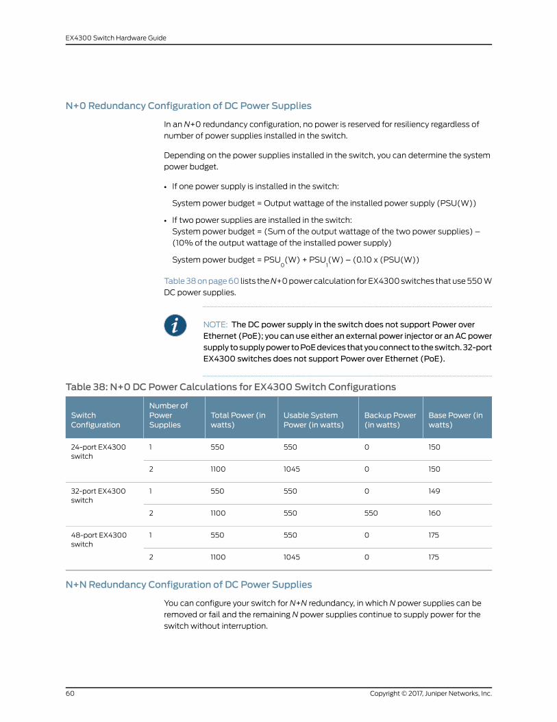
N+0 Redundancy Configuration of DC Power Supplies
In an N+0 redundancy configuration, no power is reserved for resiliency regardless of
number of power supplies installed in the switch.
Depending on the power supplies installed in the switch, you can determine the system
power budget.
• If one power supply is installed in the switch:
System power budget = Output wattage of the installed power supply (PSU(W))
• If two power supplies are installed in the switch:
System power budget = (Sum of the output wattage of the two power supplies) –
(10% of the output wattage of the installed power supply)
System power budget = PSU0(W) + PSU
1(W) – (0.10 x (PSU(W))
Table38onpage60 lists theN+0powercalculation forEX4300switches thatuse550W
DC power supplies.
NOTE: The DC power supply in the switch does not support Power overEthernet (PoE); you can use either an external power injector or anACpowersupply tosupplypower toPoEdevices thatyouconnect to theswitch.32-portEX4300 switches does not support Power over Ethernet (PoE).
Table 38: N+0 DC Power Calculations for EX4300 Switch Configurations
Base Power (inwatts)
Backup Power(in watts)
Usable SystemPower (in watts)
Total Power (inwatts)
Number ofPowerSupplies
SwitchConfiguration
1500550550124-port EX4300switch
1500104511002
1490550550132-port EX4300switch
16055055011002
1750550550148-port EX4300switch
1750104511002
N+NRedundancy Configuration of DC Power Supplies
You can configure your switch for N+N redundancy, in which N power supplies can be
removed or fail and the remaining N power supplies continue to supply power for the
switch without interruption.
Copyright © 2017, Juniper Networks, Inc.60
EX4300 Switch Hardware Guide

You can configure the power management software to manage switch power for N+N
redundancy. When you configure power management for N+N redundancy, half of the
total power available (N) is held as reserve power while the other half (N) is available
for immediate consumption. If the switch configuration changes and requires additional
power, then additional power is drawn from the reserve power, and the switch no longer
has N+N power supply redundancy. This condition raises a minor alarm. If the condition
is not corrected within 5 minutes, then amajor alarm is issued.
For more information about how power management allocates power to chassis
components when power is insufficient, see Understanding Power Management on EX
Series Switches.
Depending on the power supplies installed in the switch, you can determine the system
power budget.
• If one power supply is installed in the switch:
• System power budget = Output wattage of the installed power supply (PSU(W))
• Backup power available = 0W
Aminor alarm is raised as switch has no N+N power supply redundancy.
• If two power supplies are installed in the switch:
• Systempower budget = (Outputwattage of one power supply) – (5%of the output
wattage of one power supply)
System power budget = PSU(W) – (0.05 x PSU(W))
• Backup power available = (Output wattage of one power supply) – (5% of the
output wattage of one power supply)
System power budget = PSU(W) – (0.05 x PSU(W))
Table 39onpage61 lists theN+Npower calculation for EX4300switches that use550W
DC power supplies.
NOTE: The DC power supply in the switch does not support Power overEthernet (PoE); you can use either an external power injector or anACpowersupply tosupplypower toPoEdevices thatyouconnect to theswitch.32-portEX4300 switches does not support Power over Ethernet (PoE).
Table 39: N+NDC Power Calculations for EX4300 Switch Configurations
Base Power (inwatts)
Backup Power(in watts)
Usable SystemPower (in watts)
Total Power (inwatts)
Number ofPowerSupplies
SwitchConfiguration
1500550550124-port EX4300switch
15055055011002
61Copyright © 2017, Juniper Networks, Inc.
Chapter 4: Power Supplies

Table 39: N+NDC Power Calculations for EX4300 Switch Configurations (continued)
Base Power (inwatts)
Backup Power(in watts)
Usable SystemPower (in watts)
Total Power (inwatts)
Number ofPowerSupplies
SwitchConfiguration
1490550550132-port EX4300switch
16055055011002
1750550550148-port EX4300switch
17555055011002
RelatedDocumentation
DC Power Supply LEDs in EX4300 Switches on page 62•
• DC Power Supply Specifications for EX4300 Switches on page 104
• Installing a DC Power Supply in an EX4300 Switch on page 208
DC Power Supply LEDs in EX4300 Switches
Figure34onpage62shows the locationof theLEDsonaDCpower supply for anEX4300
switch.
Figure 34: DC Power Supply Faceplate on an EX4300 Switch
2—1— OUTOK LEDIN OK LED
Table 40 on page 62 describes the LEDs on the DC power supplies.
Table 40: DC Power Supply LEDs on an EX4300 Switch
DescriptionColorName
Indicates one of the following:
• Power supply is disconnected from DC power feed.
• DC power input voltage is not within normal operating range.
• No DC power input.
UnlitIN OK
The power supply is receiving power.Green
Copyright © 2017, Juniper Networks, Inc.62
EX4300 Switch Hardware Guide

Table 40: DC Power Supply LEDs on an EX4300 Switch (continued)
DescriptionColorName
Indicates one of the following:
• IN OK LED is unlit.
• The power supply is not delivering power correctly.
UnlitOUTOK
The power supply is functioning correctly.Green
The power supply has failed andmust be replaced.Red
RelatedDocumentation
• DC Power Supply in EX4300 Switches on page 57
• DC Power Supply Specifications for EX4300 Switches on page 104
• Connecting DC Power to an EX4300 Switch on page 159
63Copyright © 2017, Juniper Networks, Inc.
Chapter 4: Power Supplies

Copyright © 2017, Juniper Networks, Inc.64
EX4300 Switch Hardware Guide
CHAPTER 5
Viewing System Information
• Dashboard for EX Series Switches on page 65
Dashboard for EX Series Switches
NOTE: This topic applies only to the J-Web Application package.
When you log in to the J-Web user interface, the dashboard for the Juniper Networks EX
Series Ethernet Switches appears. Use the dashboard to view system information.
TheUpdateAvailablewindowappears if there is a latest updateof the J-WebApplication
package available on the Juniper Networks server. This window is enabled by the auto
update feature of J-Web.
NOTE:
• The Update Available windowwill not appear when you log in, if you havenot selected theCheck forupdatesautomaticallyonevery login in theUpdate
Preference section in theMaintain > Update J-Web side pane. By default,
the Check for update automatically on every login is selected.
• If you chooseUpdate Later, you can update to the latest J-WebApplicationpackage by clicking the orange icon next toUpdate Available on the toppane of the J-Web interface or throughMaintain > Update J-Web.
The dashboard comprises a graphical chassis viewer and four panels.
This topic describes:
• Graphical Chassis Viewer on page 66
• System Information Panel on page 67
• Health Status Panel on page 69
• Capacity Utilization Panel on page 71
• Alarms Panel on page 71
65Copyright © 2017, Juniper Networks, Inc.

• File System Usage on page 72
• Chassis Viewer on page 72
Graphical Chassis Viewer
The Dashboard panel displays a graphical view of the chassis of a switch. In a Virtual
Chassis, it displays a graphical view of eachmember switch.
InaVirtualChassis, thedefault valuesare shownon theDashboardpanelwhennochassis
image is clicked. The panel displays the value for a switch if you click its image.
NOTE: If themember switch is not present, inactive, or not provisioned, youcannot expand themember switch image.
In J-Web Application package Release 14.1X53-A2, you can form a VirtualChassisusingEX4600andEX4300switches.When inamixedVirtualChassisconsistingof EX4600switchesandEX4300switches, theEX4600switchescanbe themaster, backup, or in the linecard role,while the EX4300 switchesmust be in the linecard role.
Table 41 on page 66 lists the details that are displayed on eachmember switch.
Table 41: Details of a Virtual Chassis Member Switch
ExampleDetails
EX3300Model number of the member switch
ID 2
NOTE: If the member switch is not provisioned, the serial numberof the switch is displayed instead of its ID.
Assigned ID that applies to the entire Virtual Chassisconfiguration
Master
Possible roles are:Master, Backup, or Linecard
Role of the member switch
Prsnt
Possible statuses are: Prsnt, NotPrsnt, Inactive, or Unprvsnd
Status of the member switch
The status of themember switch is displayed on the image of the switch. If themember
switchappearsdimmed, itmeans theswitch isnotpresent, is inactive, or is notprovisioned
in theVirtualChassis. If themember switchdoesnotappeardimmed, itmeans theswitch
is present and is active.
Table 42 on page 67 describes the possible status of a member switch.
Copyright © 2017, Juniper Networks, Inc.66
EX4300 Switch Hardware Guide
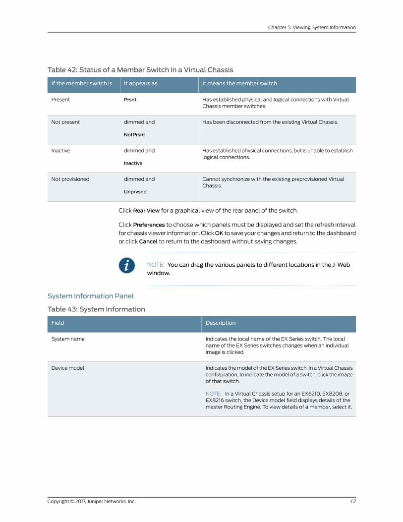
Table 42: Status of aMember Switch in a Virtual Chassis
It means themember switchIt appears asIf themember switch is
Has established physical and logical connections with VirtualChassis member switches.
PrsntPresent
Has been disconnected from the existing Virtual Chassis.dimmed and
NotPrsnt
Not present
Hasestablishedphysical connections, but is unable to establishlogical connections.
dimmed and
Inactive
Inactive
Cannot synchronize with the existing preprovisioned VirtualChassis.
dimmed and
Unprvsnd
Not provisioned
Click Rear View for a graphical view of the rear panel of the switch.
Click Preferences to choose which panels must be displayed and set the refresh interval
for chassis viewer information.ClickOK to saveyour changesand return to thedashboard
or click Cancel to return to the dashboard without saving changes.
NOTE: You can drag the various panels to different locations in the J-Webwindow.
System Information Panel
Table 43: System Information
DescriptionField
Indicates the local name of the EX Series switch. The localname of the EX Series switches changes when an individualimage is clicked.
System name
Indicates themodel of theEXSeries switch. In aVirtualChassisconfiguration, to indicate themodel of a switch, click the imageof that switch.
NOTE: In a Virtual Chassis setup for an EX6210, EX8208, orEX8216 switch, the Device model field displays details of themaster Routing Engine. To view details of a member, select it.
Device model
67Copyright © 2017, Juniper Networks, Inc.
Chapter 5: Viewing System Information
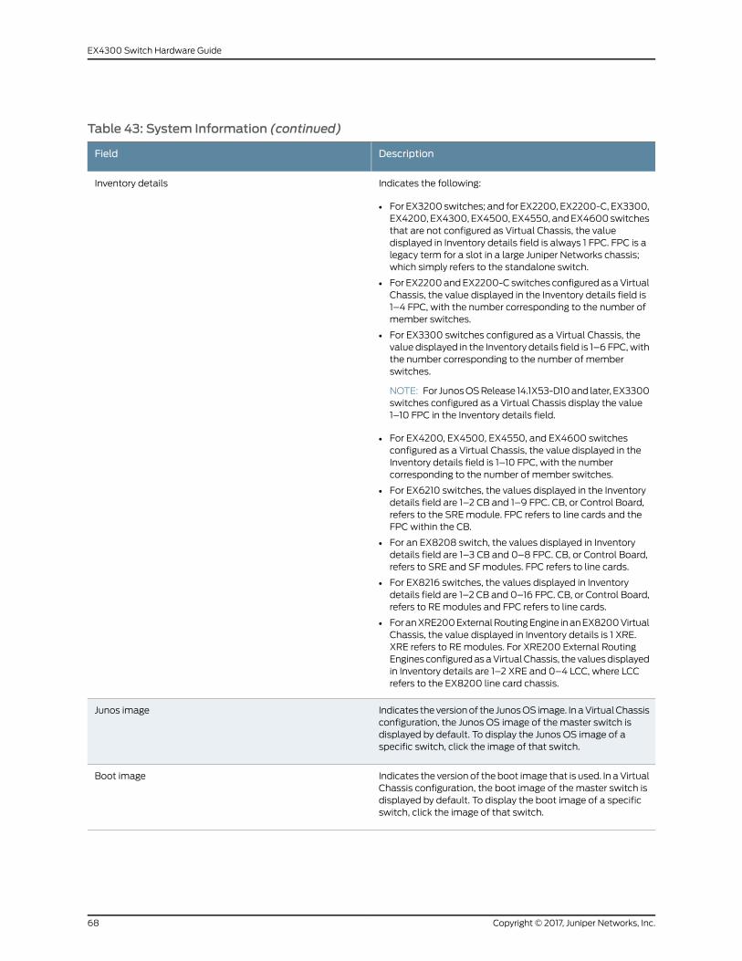
Table 43: System Information (continued)
DescriptionField
Indicates the following:
• For EX3200 switches; and for EX2200, EX2200-C, EX3300,EX4200, EX4300, EX4500, EX4550, andEX4600switchesthat are not configured as Virtual Chassis, the valuedisplayed in Inventory details field is always 1 FPC. FPC is alegacy term for a slot in a large Juniper Networks chassis;which simply refers to the standalone switch.
• For EX2200andEX2200-C switches configured as aVirtualChassis, the value displayed in the Inventory details field is1–4 FPC, with the number corresponding to the number ofmember switches.
• For EX3300 switches configured as a Virtual Chassis, thevalue displayed in the Inventory details field is 1–6 FPC,withthe number corresponding to the number of memberswitches.
NOTE: For JunosOSRelease 14.1X53-D10and later, EX3300switches configured as a Virtual Chassis display the value1–10 FPC in the Inventory details field.
• For EX4200, EX4500, EX4550, and EX4600 switchesconfigured as a Virtual Chassis, the value displayed in theInventory details field is 1–10 FPC, with the numbercorresponding to the number of member switches.
• For EX6210 switches, the values displayed in the Inventorydetails field are 1–2 CB and 1–9 FPC. CB, or Control Board,refers to the SREmodule. FPC refers to line cards and theFPC within the CB.
• For an EX8208 switch, the values displayed in Inventorydetails field are 1–3 CB and 0–8 FPC. CB, or Control Board,refers to SRE and SFmodules. FPC refers to line cards.
• For EX8216 switches, the values displayed in Inventorydetails field are 1–2 CB and 0–16 FPC. CB, or Control Board,refers to REmodules and FPC refers to line cards.
• ForanXRE200ExternalRoutingEngine inanEX8200VirtualChassis, the value displayed in Inventory details is 1 XRE.XRE refers to REmodules. For XRE200 External RoutingEngines configuredasaVirtualChassis, the valuesdisplayedin Inventory details are 1–2 XRE and 0–4 LCC, where LCCrefers to the EX8200 line card chassis.
Inventory details
Indicates theversionof the JunosOS image. In aVirtualChassisconfiguration, the Junos OS image of the master switch isdisplayed by default. To display the Junos OS image of aspecific switch, click the image of that switch.
Junos image
Indicates the version of theboot image that is used. In aVirtualChassis configuration, the boot image of the master switch isdisplayed by default. To display the boot image of a specificswitch, click the image of that switch.
Boot image
Copyright © 2017, Juniper Networks, Inc.68
EX4300 Switch Hardware Guide
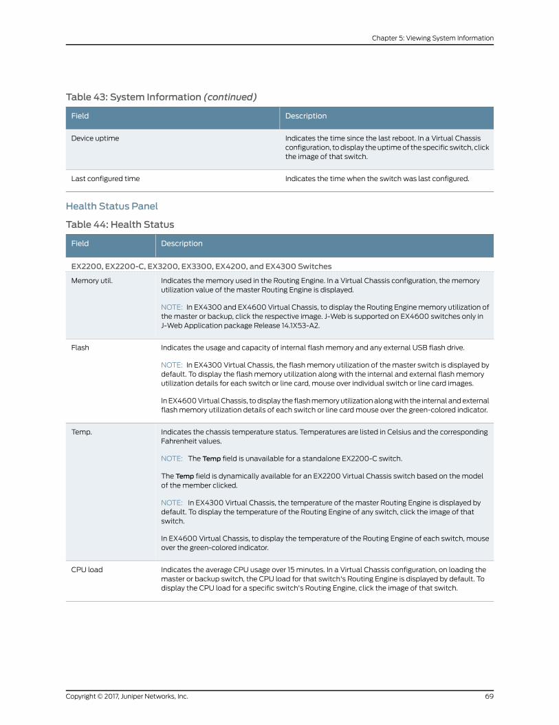
Table 43: System Information (continued)
DescriptionField
Indicates the time since the last reboot. In a Virtual Chassisconfiguration, todisplay theuptimeof the specific switch, clickthe image of that switch.
Device uptime
Indicates the time when the switch was last configured.Last configured time
Health Status Panel
Table 44: Health Status
DescriptionField
EX2200, EX2200-C, EX3200, EX3300, EX4200, and EX4300 Switches
Indicates the memory used in the Routing Engine. In a Virtual Chassis configuration, the memoryutilization value of the master Routing Engine is displayed.
NOTE: In EX4300 and EX4600 Virtual Chassis, to display the Routing Enginememory utilization ofthe master or backup, click the respective image. J-Web is supported on EX4600 switches only inJ-Web Application package Release 14.1X53-A2.
Memory util.
Indicates the usage and capacity of internal flash memory and any external USB flash drive.
NOTE: In EX4300 Virtual Chassis, the flashmemory utilization of themaster switch is displayed bydefault. To display the flash memory utilization along with the internal and external flash memoryutilization details for each switch or line card, mouse over individual switch or line card images.
InEX4600VirtualChassis, todisplay the flashmemoryutilizationalongwith the internal andexternalflash memory utilization details of each switch or line card mouse over the green-colored indicator.
Flash
Indicates the chassis temperature status. Temperatures are listed in Celsius and the correspondingFahrenheit values.
NOTE: The Temp field is unavailable for a standalone EX2200-C switch.
The Temp field is dynamically available for an EX2200 Virtual Chassis switch based on themodelof the member clicked.
NOTE: In EX4300 Virtual Chassis, the temperature of the master Routing Engine is displayed bydefault. To display the temperature of the Routing Engine of any switch, click the image of thatswitch.
In EX4600 Virtual Chassis, to display the temperature of the Routing Engine of each switch, mouseover the green-colored indicator.
Temp.
Indicates the average CPU usage over 15 minutes. In a Virtual Chassis configuration, on loading themaster or backup switch, the CPU load for that switch's Routing Engine is displayed by default. Todisplay the CPU load for a specific switch's Routing Engine, click the image of that switch.
CPU load
69Copyright © 2017, Juniper Networks, Inc.
Chapter 5: Viewing System Information

Table 44: Health Status (continued)
DescriptionField
Indicates the status of the fans in the fan tray. The possible values areOK, Failed, and Absent. In aVirtual Chassis configuration, the fan status of the master switch is displayed by default. To displaythe fan status for any switch , click the image of that switch.
NOTE: The Fan status field is unavailable for a standalone EX2200-C switch.
The Fan status field is dynamically available for an EX2200 Virtual Chassis switch based on themodel of the member clicked.
In EX4600 Virtual Chassis, mouse over the fan icon to display the fan status of all the switches.
Fan status
EX4500 and EX4550 Switches
Indicates the memory used in the Routing Engine. In a Virtual Chassis configuration, the memoryutilization value of the master Routing Engine is displayed.
Memory util.
Indicates the usage and capacity of internal flash memory and any external USB flash drive.Flash
Indicates the chassis temperature status. Temperatures in the dashboard are listed in Celsius andthe corresponding Fahrenheit values.
NOTE: The Temp field is unavailable for an EX4500 switch.
Temp.
Indicates the average CPU usage over 15 minutes.CPU load
Indicates the status of the fans in the fan tray. The possible values areOK, Failed, and Absent. Thisfield also indicates the direction of airflow of the fan tray. The possible values are Front to back andBack to front.
Fan status
EX6210 Switches
Indicates the memory used in the master Routing Engine. Click the backup Routing Engine to viewthememory used in the backup Routing Engine.
Memory util.
Indicates the average CPU usage over 15 minutes.CPU load
Indicates the usage and capacity of internal flash memory and any external USB flash drive.Flash
Indicates the status of the fans in the fan tray. The possible values areOK, Failed, and Absent.Fan status
EX8208 Switches
Indicates thememoryused in theexternalRoutingEngine. InanEX8200VirtualChassis, thememoryutilization value of the XRE200 External Routing Engine in the master role is displayed. Click theXRE200 External Routing Engine in the backup role to view thememory used in the backup externalRouting Engine.
Memory util.
Indicates the average CPU usage over 15 minutes.CPU load
Indicates the usage and capacity of internal flash memory and any external USB flash drive.Flash
EX8216 Switches
Copyright © 2017, Juniper Networks, Inc.70
EX4300 Switch Hardware Guide
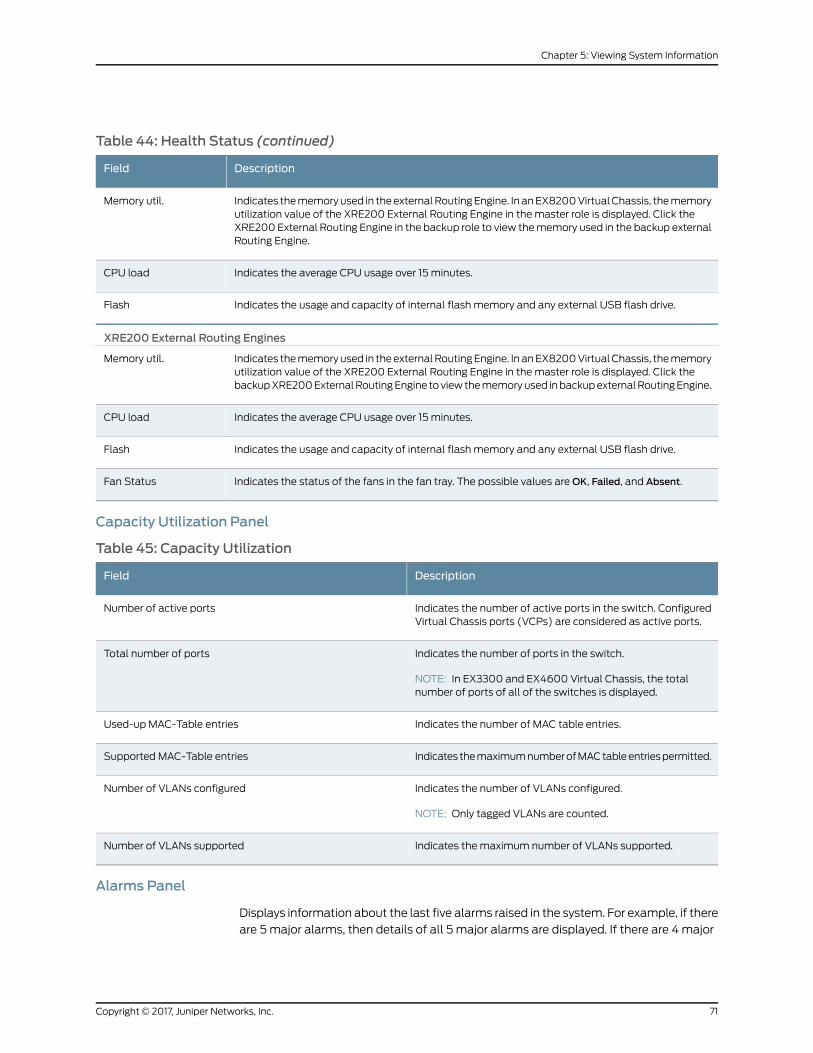
Table 44: Health Status (continued)
DescriptionField
Indicates thememoryused in theexternalRoutingEngine. InanEX8200VirtualChassis, thememoryutilization value of the XRE200 External Routing Engine in the master role is displayed. Click theXRE200 External Routing Engine in the backup role to view thememory used in the backup externalRouting Engine.
Memory util.
Indicates the average CPU usage over 15 minutes.CPU load
Indicates the usage and capacity of internal flash memory and any external USB flash drive.Flash
XRE200 External Routing Engines
Indicates thememoryused in theexternalRoutingEngine. InanEX8200VirtualChassis, thememoryutilization value of the XRE200 External Routing Engine in the master role is displayed. Click thebackupXRE200ExternalRoutingEngine toviewthememoryused inbackupexternalRoutingEngine.
Memory util.
Indicates the average CPU usage over 15 minutes.CPU load
Indicates the usage and capacity of internal flash memory and any external USB flash drive.Flash
Indicates the status of the fans in the fan tray. The possible values areOK, Failed, and Absent.Fan Status
Capacity Utilization Panel
Table 45: Capacity Utilization
DescriptionField
Indicates the number of active ports in the switch. ConfiguredVirtual Chassis ports (VCPs) are considered as active ports.
Number of active ports
Indicates the number of ports in the switch.
NOTE: In EX3300 and EX4600 Virtual Chassis, the totalnumber of ports of all of the switches is displayed.
Total number of ports
Indicates the number of MAC table entries.Used-up MAC-Table entries
Indicates themaximumnumberofMACtableentriespermitted.Supported MAC-Table entries
Indicates the number of VLANs configured.
NOTE: Only tagged VLANs are counted.
Number of VLANs configured
Indicates the maximum number of VLANs supported.Number of VLANs supported
Alarms Panel
Displays information about the last five alarms raised in the system. For example, if there
are 5major alarms, then details of all 5 major alarms are displayed. If there are 4major
71Copyright © 2017, Juniper Networks, Inc.
Chapter 5: Viewing System Information
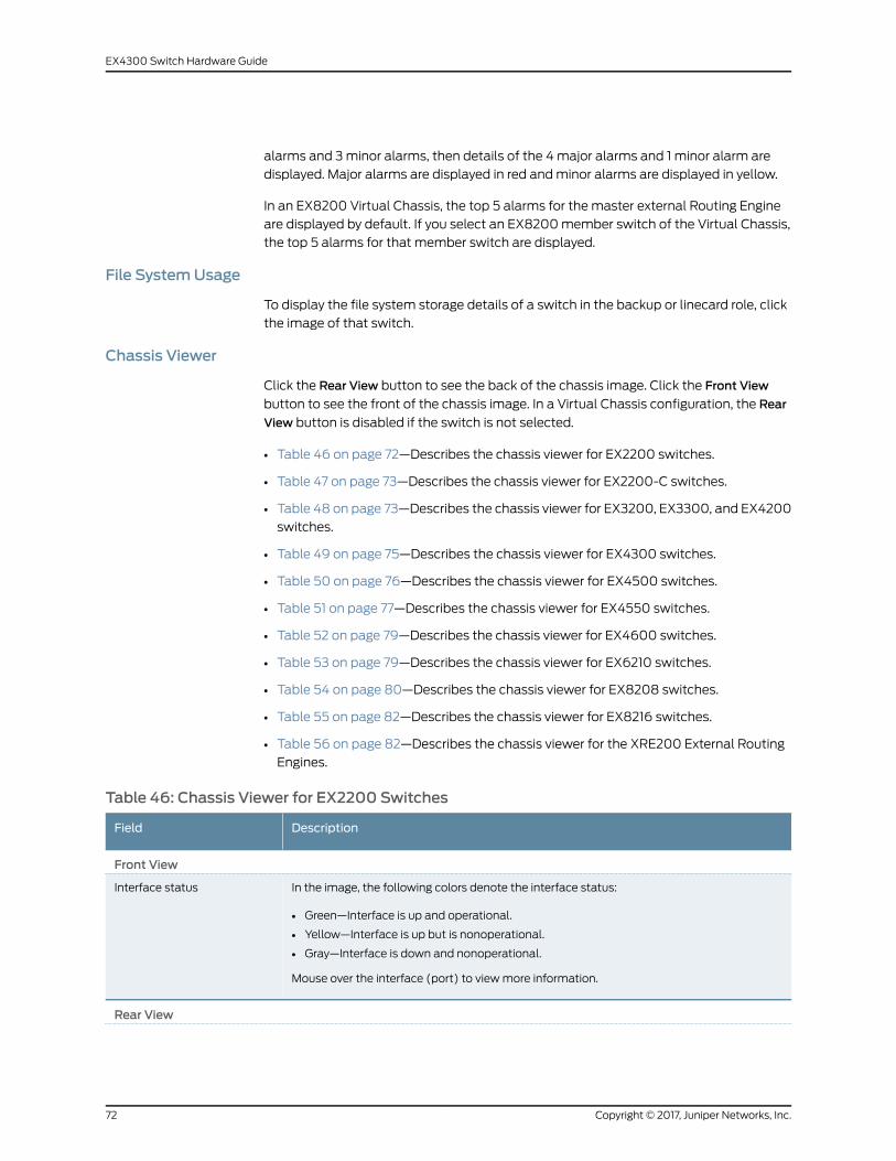
alarms and 3minor alarms, then details of the 4major alarms and 1 minor alarm are
displayed. Major alarms are displayed in red andminor alarms are displayed in yellow.
In an EX8200 Virtual Chassis, the top 5 alarms for the master external Routing Engine
are displayed by default. If you select an EX8200member switch of the Virtual Chassis,
the top 5 alarms for that member switch are displayed.
File SystemUsage
To display the file system storage details of a switch in the backup or linecard role, click
the image of that switch.
Chassis Viewer
Click the Rear View button to see the back of the chassis image. Click the Front View
button to see the front of the chassis image. In a Virtual Chassis configuration, the Rear
View button is disabled if the switch is not selected.
• Table 46 on page 72—Describes the chassis viewer for EX2200 switches.
• Table 47 on page 73—Describes the chassis viewer for EX2200-C switches.
• Table 48 on page 73—Describes the chassis viewer for EX3200, EX3300, and EX4200
switches.
• Table 49 on page 75—Describes the chassis viewer for EX4300 switches.
• Table 50 on page 76—Describes the chassis viewer for EX4500 switches.
• Table 51 on page 77—Describes the chassis viewer for EX4550 switches.
• Table 52 on page 79—Describes the chassis viewer for EX4600 switches.
• Table 53 on page 79—Describes the chassis viewer for EX6210 switches.
• Table 54 on page 80—Describes the chassis viewer for EX8208 switches.
• Table 55 on page 82—Describes the chassis viewer for EX8216 switches.
• Table 56 on page 82—Describes the chassis viewer for the XRE200 External Routing
Engines.
Table 46: Chassis Viewer for EX2200 Switches
DescriptionField
Front View
In the image, the following colors denote the interface status:
• Green—Interface is up and operational.
• Yellow—Interface is up but is nonoperational.
• Gray—Interface is down and nonoperational.
Mouse over the interface (port) to viewmore information.
Interface status
Rear View
Copyright © 2017, Juniper Networks, Inc.72
EX4300 Switch Hardware Guide

Table 46: Chassis Viewer for EX2200 Switches (continued)
DescriptionField
Themanagement port is used to connect the switch to amanagement device for out-of-bandmanagement.
Management (me0) port
The console port is used to connect the switch to amanagement console or to a consoleserver. (Youmight do this for initial switch configuration.)
Console port
Indicates the USB port for the switch.
NOTE: We recommend that you use USB flash drives purchased from Juniper Networks foryour EX Series switch.
USB port
Mouse over the fan tray icon to display name, status, and description information.Fan tray
Mouse over the power outlet icon to display name, status, and description information.Power supply
Table 47: Chassis Viewer for EX2200-C Switches
DescriptionField
Front View
In the image, the following colors denote the interface status:
• Green—Interface is up and operational.
• Yellow—Interface is up but is nonoperational.
• Gray—Interface is down and nonoperational.
Mouse over the interface (port) to viewmore information.
Interface status
Themanagementport is used to connect the switch toamanagementdevice for out-of-bandmanagement.
Management (me0) port
The console port is used to connect the switch to amanagement console or to a consoleserver. (Youmight do this for initial switch configuration.)
Console port
Indicates the USB port for the switch.
NOTE: We recommend that you use USB flash drives purchased from Juniper Networks foryour EX Series switch.
USB port
Rear View
Mouse over the power outlet icon to display name, status, and description information.Power supply
Table 48: Chassis Viewer for EX3200, EX3300, and EX4200 Switches
DescriptionField
Front View
73Copyright © 2017, Juniper Networks, Inc.
Chapter 5: Viewing System Information

Table 48: Chassis Viewer for EX3200, EX3300, and EX4200 Switches (continued)
DescriptionField
In the image, the following colors denote the interface status:
• Green—Interface is up and operational.
• Yellow—Interface is up but is nonoperational.
• Gray—Interface is down and nonoperational.
Mouse over the interface (port) to viewmore information.
For a Virtual Chassis configuration, select the switch to view the interface status.
If an SFP+ uplink module is installed in the switch, mouse over the port icon to display whetherthe module is configured to operate in 1-gigabit mode or in 10-gigabit mode. If the module isconfigured to operate in 1-gigabit mode, the tool tip information is displayed for all 4 ports. If themodule is configured to operate in 10-gigabit mode, the tool tip information is displayed only for2 ports.
On an EX3300 switch with the 4x GE/XE SFP+module, mouse over the port icon to displaywhether the module is configured to operate in 1-gigabit mode or 10-gigabit mode.
For SFP, SFP+, and XFP ports, the interfaces appear dimmed if no transceiver is inserted. Thechassis viewer displays Transceiver not plugged-inwhen youmouse over the port icon.
Interface status
LCD panel configured for the LEDs on the ports. Mouse over the icon to view the current characterdisplay.
LCD panel
Rear View of the EX3200 Switch
Themanagement port is used to connect the switch to amanagement device for out-of-bandmanagement.
Management (me0) port
The console port is used to connect the switch to amanagement console or to a console server.(Youmight do this for initial switch configuration.)
Console port
Indicates the USB port for the switch.
NOTE: We recommend that you use USB flash drives purchased from Juniper Networks for yourEX Series switch.
USB port
Mouse over the fan tray icon to display name, status, and description information.Fan tray
Mouse over the power supply icon to display name, status, and description information.Power supply
Rear View of the EX3300 and EX4200 Switch
Mouse over the fan tray icon to display name, status, and description information. For a VirtualChassis, the status of the fans of the selectedmember switch is displayed.
Fan tray
Displayed only when EX4200 switches are configured as a Virtual Chassis. The following colorsdenote the Virtual Chassis port (VCP) status:
• Green—VCP is up and operational.
• Yellow—VCP is up but is nonoperational.
• Gray—VCP is down and nonoperational.
Virtual Chassis port
Copyright © 2017, Juniper Networks, Inc.74
EX4300 Switch Hardware Guide
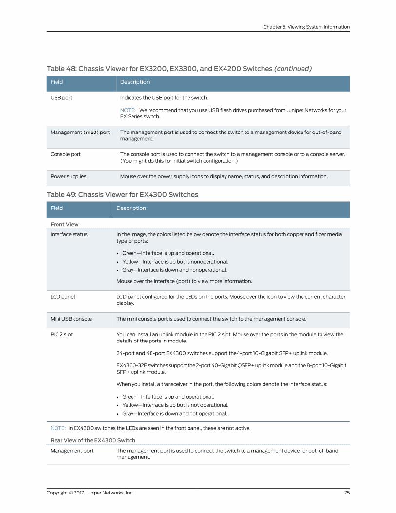
Table 48: Chassis Viewer for EX3200, EX3300, and EX4200 Switches (continued)
DescriptionField
Indicates the USB port for the switch.
NOTE: We recommend that you use USB flash drives purchased from Juniper Networks for yourEX Series switch.
USB port
Themanagement port is used to connect the switch to amanagement device for out-of-bandmanagement.
Management (me0) port
The console port is used to connect the switch to amanagement console or to a console server.(Youmight do this for initial switch configuration.)
Console port
Mouse over the power supply icons to display name, status, and description information.Power supplies
Table 49: Chassis Viewer for EX4300 Switches
DescriptionField
Front View
In the image, the colors listed below denote the interface status for both copper and fiber mediatype of ports:
• Green—Interface is up and operational.
• Yellow—Interface is up but is nonoperational.
• Gray—Interface is down and nonoperational.
Mouse over the interface (port) to viewmore information.
Interface status
LCD panel configured for the LEDs on the ports. Mouse over the icon to view the current characterdisplay.
LCD panel
Themini console port is used to connect the switch to the management console.Mini USB console
You can install an uplink module in the PIC 2 slot. Mouse over the ports in the module to view thedetails of the ports in module.
24-port and 48-port EX4300 switches support the4-port 10-Gigabit SFP+ uplink module.
EX4300-32Fswitchessupport the2-port40-GigabitQSFP+uplinkmoduleandthe8-port 10-GigabitSFP+ uplink module.
When you install a transceiver in the port, the following colors denote the interface status:
• Green—Interface is up and operational.
• Yellow—Interface is up but is not operational.
• Gray—Interface is down and not operational.
PIC 2 slot
NOTE: In EX4300 switches the LEDs are seen in the front panel, these are not active.
Rear View of the EX4300 Switch
Themanagement port is used to connect the switch to amanagement device for out-of-bandmanagement.
Management port
75Copyright © 2017, Juniper Networks, Inc.
Chapter 5: Viewing System Information
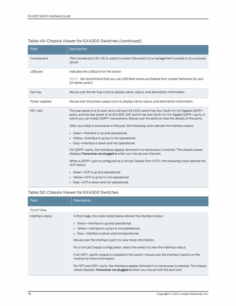
Table 49: Chassis Viewer for EX4300 Switches (continued)
DescriptionField
The Console port (RJ-45) is used to connect the switch to amanagement console or to a consoleserver.
Console port
Indicates the USB port for the switch.
NOTE: We recommend that you use USB flash drives purchased from Juniper Networks for yourEX Series switch.
USB port
Mouse over the fan tray icons to display name, status, and description information.Fan tray
Mouse over the power supply icons to display name, status, and description information.Power supplies
The rear panel of a 24-port and a 48-port EX4300 switch has four (built-in) 40-Gigabit QSFP+ports, and the rear panel of an EX4300-32F switch has two (built-in) 40-Gigabit QSFP+ ports, inwhich you can install QSFP+ transceivers. Mouse over the ports to view the details of the ports.
After you install a transceiver in the port, the following colors denote the interface status:
• Green—Interface is up and operational.
• Yellow—Interface is up but is not operational.
• Gray—Interface is down and not operational.
For QSFP+ ports, the interfaces appear dimmed if no transceiver is inserted. The chassis viewerdisplays Transceiver not plugged inwhen youmouse over the port.
When a QSFP+ port is configured as a Virtual Chassis Port (VCP), the following colors denote theVCP status:
• Green—VCP is up and operational.
• Yellow—VCP is up but is not operational.
• Gray—VCP is down and not operational.
PIC 1 slot
Table 50: Chassis Viewer for EX4500 Switches
DescriptionField
Front View
In the image, the colors listed below denote the interface status:
• Green—Interface is up and operational.
• Yellow—Interface is up but is nonoperational.
• Gray—Interface is down and nonoperational.
Mouse over the interface (port) to viewmore information.
For a Virtual Chassis configuration, select the switch to view the interface status.
If an SFP+ uplink module is installed in the switch, mouse over the interface (ports) on themodule for more information.
For SFP and SFP+ ports, the interfaces appear dimmed if no transceiver is inserted. The chassisviewer displays Transceiver not plugged-inwhen youmouse over the port icon.
Interface status
Copyright © 2017, Juniper Networks, Inc.76
EX4300 Switch Hardware Guide
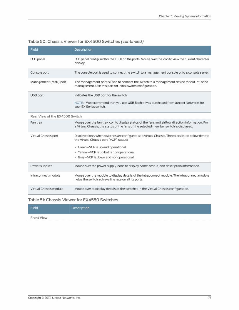
Table 50: Chassis Viewer for EX4500 Switches (continued)
DescriptionField
LCDpanel configured for theLEDson theports.Mouseover the icon toview thecurrent characterdisplay.
LCD panel
The console port is used to connect the switch to amanagement console or to a console server.Console port
Themanagement port is used to connect the switch to amanagement device for out-of-bandmanagement. Use this port for initial switch configuration.
Management (me0) port
Indicates the USB port for the switch.
NOTE: We recommend that you use USB flash drives purchased from Juniper Networks foryour EX Series switch.
USB port
Rear View of the EX4500 Switch
Mouse over the fan tray icon to display status of the fans and airflow direction information. Fora Virtual Chassis, the status of the fans of the selectedmember switch is displayed.
Fan tray
Displayedonlywhen switches are configuredasaVirtual Chassis. The colors listedbelowdenotethe Virtual Chassis port (VCP) status:
• Green—VCP is up and operational.
• Yellow—VCP is up but is nonoperational.
• Gray—VCP is down and nonoperational.
Virtual Chassis port
Mouse over the power supply icons to display name, status, and description information.Power supplies
Mouse over themodule to display details of the intraconnectmodule. The intraconnectmodulehelps the switch achieve line rate on all its ports.
Intraconnect module
Mouse over to display details of the switches in the Virtual Chassis configuration.Virtual Chassis module
Table 51: Chassis Viewer for EX4550 Switches
DescriptionField
Front View
77Copyright © 2017, Juniper Networks, Inc.
Chapter 5: Viewing System Information
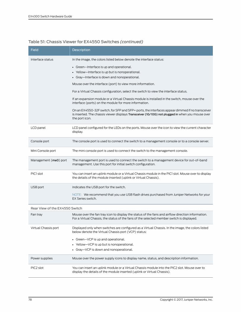
Table 51: Chassis Viewer for EX4550 Switches (continued)
DescriptionField
In the image, the colors listed below denote the interface status:
• Green—Interface is up and operational.
• Yellow—Interface is up but is nonoperational.
• Gray—Interface is down and nonoperational.
Mouse over the interface (port) to viewmore information.
For a Virtual Chassis configuration, select the switch to view the interface status.
If an expansion module or a Virtual Chassis module is installed in the switch, mouse over theinterface (ports) on themodule for more information.
OnanEX4550-32F switch, forSFPandSFP+ports, the interfacesappeardimmed if no transceiveris inserted. The chassis viewer displays Transceiver (1G/10G) not plugged inwhen youmouse overthe port icon.
Interface status
LCD panel configured for the LEDs on the ports. Mouse over the icon to view the current characterdisplay.
LCD panel
The console port is used to connect the switch to amanagement console or to a console server.Console port
Themini console port is used to connect the switch to the management console.Mini Console port
Themanagement port is used to connect the switch to amanagement device for out-of-bandmanagement. Use this port for initial switch configuration.
Management (me0) port
You can insert an uplinkmodule or a Virtual Chassismodule in the PIC1 slot. Mouse over to displaythe details of the module inserted (uplink or Virtual Chassis).
PIC1 slot
Indicates the USB port for the switch.
NOTE: We recommend that you use USB flash drives purchased from Juniper Networks for yourEX Series switch.
USB port
Rear View of the EX4550 Switch
Mouse over the fan tray icon to display the status of the fans and airflow direction information.For a Virtual Chassis, the status of the fans of the selectedmember switch is displayed.
Fan tray
Displayed only when switches are configured as a Virtual Chassis. In the image, the colors listedbelow denote the Virtual Chassis port (VCP) status:
• Green—VCP is up and operational.
• Yellow—VCP is up but is nonoperational.
• Gray—VCP is down and nonoperational.
Virtual Chassis port
Mouse over the power supply icons to display name, status, and description information.Power supplies
You can insert an uplink module or a Virtual Chassis module into the PIC2 slot. Mouse over todisplay the details of the module inserted (uplink or Virtual Chassis).
PIC2 slot
Copyright © 2017, Juniper Networks, Inc.78
EX4300 Switch Hardware Guide
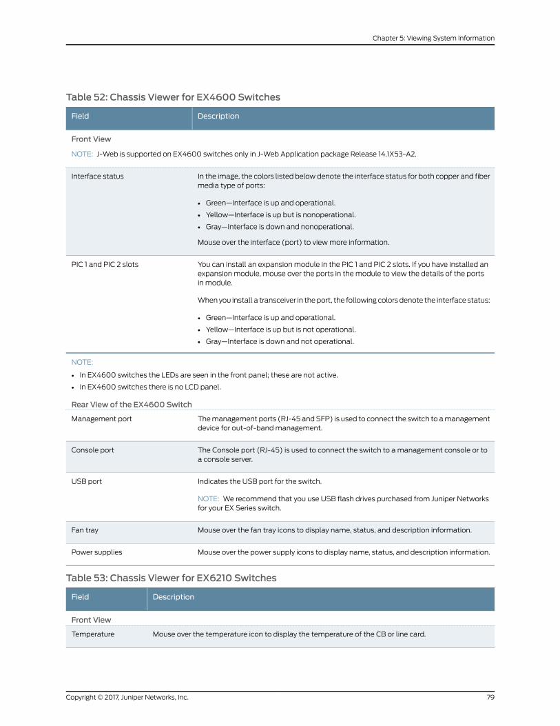
Table 52: Chassis Viewer for EX4600 Switches
DescriptionField
Front View
NOTE: J-Web is supported on EX4600 switches only in J-Web Application package Release 14.1X53-A2.
In the image, the colors listed belowdenote the interface status for both copper and fibermedia type of ports:
• Green—Interface is up and operational.
• Yellow—Interface is up but is nonoperational.
• Gray—Interface is down and nonoperational.
Mouse over the interface (port) to viewmore information.
Interface status
You can install an expansion module in the PIC 1 and PIC 2 slots. If you have installed anexpansion module, mouse over the ports in the module to view the details of the portsin module.
When you install a transceiver in theport, the following colors denote the interface status:
• Green—Interface is up and operational.
• Yellow—Interface is up but is not operational.
• Gray—Interface is down and not operational.
PIC 1 and PIC 2 slots
NOTE:
• In EX4600 switches the LEDs are seen in the front panel; these are not active.
• In EX4600 switches there is no LCD panel.
Rear View of the EX4600 Switch
Themanagement ports (RJ-45 andSFP) is used to connect the switch to amanagementdevice for out-of-bandmanagement.
Management port
The Console port (RJ-45) is used to connect the switch to amanagement console or toa console server.
Console port
Indicates the USB port for the switch.
NOTE: We recommend that you use USB flash drives purchased from Juniper Networksfor your EX Series switch.
USB port
Mouse over the fan tray icons to display name, status, and description information.Fan tray
Mouse over the power supply icons to display name, status, and description information.Power supplies
Table 53: Chassis Viewer for EX6210 Switches
DescriptionField
Front View
Mouse over the temperature icon to display the temperature of the CB or line card.Temperature
79Copyright © 2017, Juniper Networks, Inc.
Chapter 5: Viewing System Information

Table 53: Chassis Viewer for EX6210 Switches (continued)
DescriptionField
Select the CB or line card.
In the image, the colors listed below denote the interface status:
• Green—Interface is up and operational.
• Yellow—Interface is up but is nonoperational.
• Gray—Interface is down and nonoperational.
Mouse over the interface (port) to viewmore information.
You can view status for the following ports on the SREmodule:
• USB port—Indicates the USB port for the switch.
NOTE: We recommend that you use USB flash drives purchased from Juniper Networks for yourEX Series switch.
• Management (me0) port—Themanagement port is used to connect the switch to amanagementdevice for out-of-bandmanagement. There are 2 management ports: fiber and copper. The samestatus is displayed for both theme0 ports.
• Console port—The console port is used to connect the switch to amanagement console or to aconsole server. (Youmight do this for initial switch configuration.)
CBs support 4 SFP+ uplink ports. Mouse over the interface on the CB for more information.
For SFP and SFP+ ports, the interfaces appear dimmed if no transceiver is inserted. The chassis viewerdisplays Transceiver not plugged-inwhen youmouse over the port icon.
Interface status
Mouse over the power supply icons to display name, status, and description information.Power supplies
LCD panel configured for the LEDs on the ports. Mouse over the icon to view the current characterdisplayof themasterRoutingEngine.TheEX6210switchhas2LCDpanels, one for eachRoutingEngine.The backup Routing Engine LCD displays Backup.
LCD panel
Rear View of the EX6210 Switch
Mouse over the fan tray icon to display information regarding the cooling fans.Fan tray
Table 54: Chassis Viewer for EX8208 Switches
DescriptionField
Front View
Copyright © 2017, Juniper Networks, Inc.80
EX4300 Switch Hardware Guide

Table 54: Chassis Viewer for EX8208 Switches (continued)
DescriptionField
In the image, click any line card, SREmodule, or SFmodule to view the front view of the selectedcomponent. In the image, the colors listed below denote the interface status:
• Green—Interface is up and operational.
• Yellow—Interface is up but is nonoperational.
• Gray—Interface is down and nonoperational.
Mouse over the interface (port) to viewmore information.
You can view status for the following ports on the SREmodule:
• USB port—Indicates the USB port for the switch.
NOTE: We recommend that you use USB flash drives purchased from Juniper Networks for yourEX Series switch.
• Auxiliary port—This port is unavailable.
• Management (me0) port—Themanagement port is used to connect the switch to amanagementdevice for out-of-bandmanagement.
• Console port—The console port is used to connect the switch to amanagement console or to aconsole server. (Youmight do this for initial switch configuration.)
Because the SFmodule has no ports, no status information is displayed.
Interface status
Slots on the switch are labeled, from the top of the switch down:
• 0–3 (line cards)
• SRE0, SF, SRE1 (SRE and SFmodules)
• 4–7 (line cards)
Slot numbers
The active slots contain a gray temperature icon. Mouse over the icon to display temperatureinformation for the slot.
Temperature
Mouse over the fan tray icon to display name, status, and description information.Fan status
Mouse over the power supply icons to display name, status, and description information.Power supplies
LCD panel configured for the LEDs on the ports. Mouse over the icon to view the current characterdisplay.
LCD panel
The EX8208 switch does not have any components on the rear of the chassis.Rear View
81Copyright © 2017, Juniper Networks, Inc.
Chapter 5: Viewing System Information
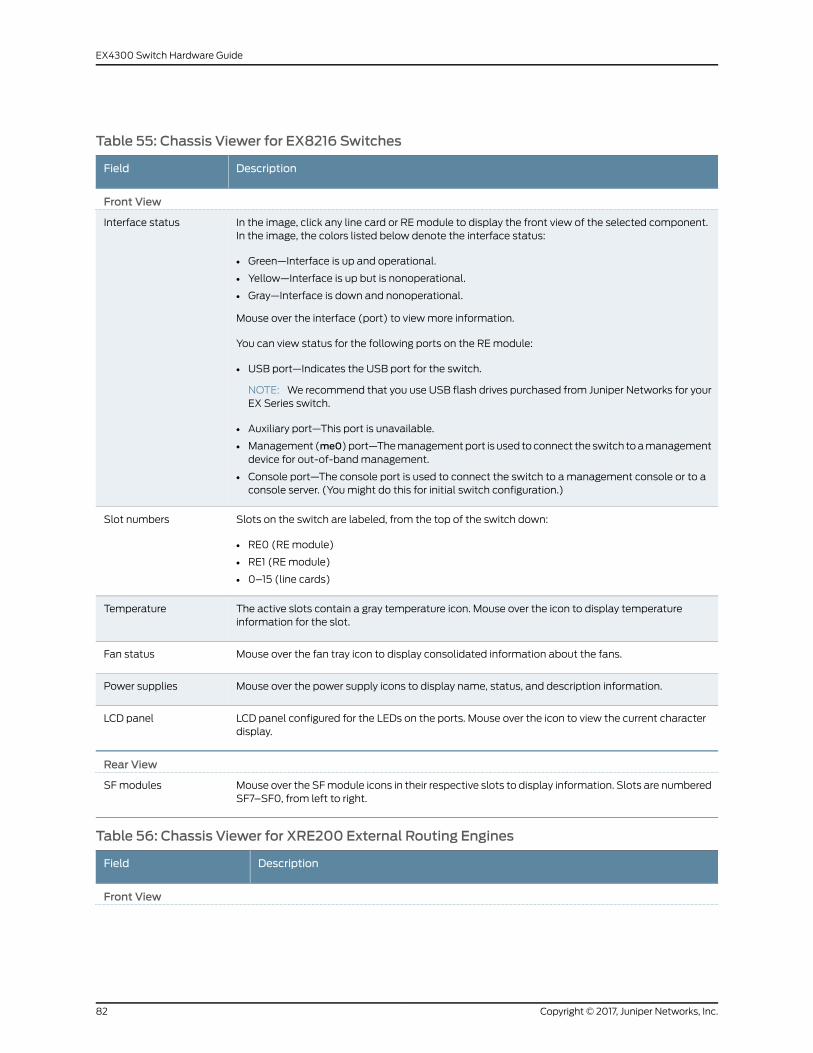
Table 55: Chassis Viewer for EX8216 Switches
DescriptionField
Front View
In the image, click any line card or REmodule to display the front view of the selected component.In the image, the colors listed below denote the interface status:
• Green—Interface is up and operational.
• Yellow—Interface is up but is nonoperational.
• Gray—Interface is down and nonoperational.
Mouse over the interface (port) to viewmore information.
You can view status for the following ports on the REmodule:
• USB port—Indicates the USB port for the switch.
NOTE: We recommend that you use USB flash drives purchased from Juniper Networks for yourEX Series switch.
• Auxiliary port—This port is unavailable.
• Management (me0)port—Themanagementport is used toconnect the switch toamanagementdevice for out-of-bandmanagement.
• Console port—The console port is used to connect the switch to amanagement console or to aconsole server. (Youmight do this for initial switch configuration.)
Interface status
Slots on the switch are labeled, from the top of the switch down:
• RE0 (REmodule)
• RE1 (REmodule)
• 0–15 (line cards)
Slot numbers
The active slots contain a gray temperature icon. Mouse over the icon to display temperatureinformation for the slot.
Temperature
Mouse over the fan tray icon to display consolidated information about the fans.Fan status
Mouse over the power supply icons to display name, status, and description information.Power supplies
LCD panel configured for the LEDs on the ports. Mouse over the icon to view the current characterdisplay.
LCD panel
Rear View
Mouse over the SFmodule icons in their respective slots to display information. Slots are numberedSF7–SF0, from left to right.
SF modules
Table 56: Chassis Viewer for XRE200 External Routing Engines
DescriptionField
Front View
Copyright © 2017, Juniper Networks, Inc.82
EX4300 Switch Hardware Guide
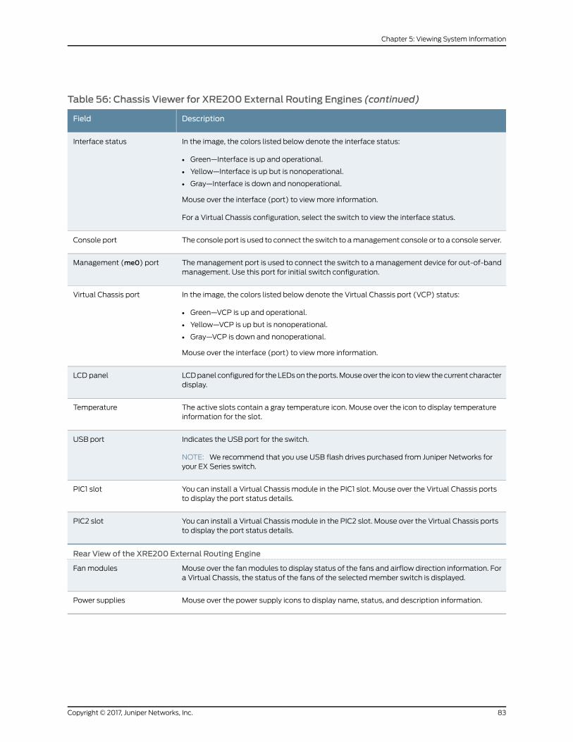
Table 56: Chassis Viewer for XRE200 External Routing Engines (continued)
DescriptionField
In the image, the colors listed below denote the interface status:
• Green—Interface is up and operational.
• Yellow—Interface is up but is nonoperational.
• Gray—Interface is down and nonoperational.
Mouse over the interface (port) to viewmore information.
For a Virtual Chassis configuration, select the switch to view the interface status.
Interface status
The console port is used to connect the switch to amanagement console or to a console server.Console port
Themanagement port is used to connect the switch to amanagement device for out-of-bandmanagement. Use this port for initial switch configuration.
Management (me0) port
In the image, the colors listed below denote the Virtual Chassis port (VCP) status:
• Green—VCP is up and operational.
• Yellow—VCP is up but is nonoperational.
• Gray—VCP is down and nonoperational.
Mouse over the interface (port) to viewmore information.
Virtual Chassis port
LCDpanel configured for theLEDson theports.Mouseover the icon toviewthecurrent characterdisplay.
LCD panel
The active slots contain a gray temperature icon. Mouse over the icon to display temperatureinformation for the slot.
Temperature
Indicates the USB port for the switch.
NOTE: We recommend that you use USB flash drives purchased from Juniper Networks foryour EX Series switch.
USB port
You can install a Virtual Chassis module in the PIC1 slot. Mouse over the Virtual Chassis portsto display the port status details.
PIC1 slot
You can install a Virtual Chassis module in the PIC2 slot. Mouse over the Virtual Chassis portsto display the port status details.
PIC2 slot
Rear View of the XRE200 External Routing Engine
Mouse over the fanmodules to display status of the fans and airflow direction information. Fora Virtual Chassis, the status of the fans of the selectedmember switch is displayed.
Fanmodules
Mouse over the power supply icons to display name, status, and description information.Power supplies
83Copyright © 2017, Juniper Networks, Inc.
Chapter 5: Viewing System Information
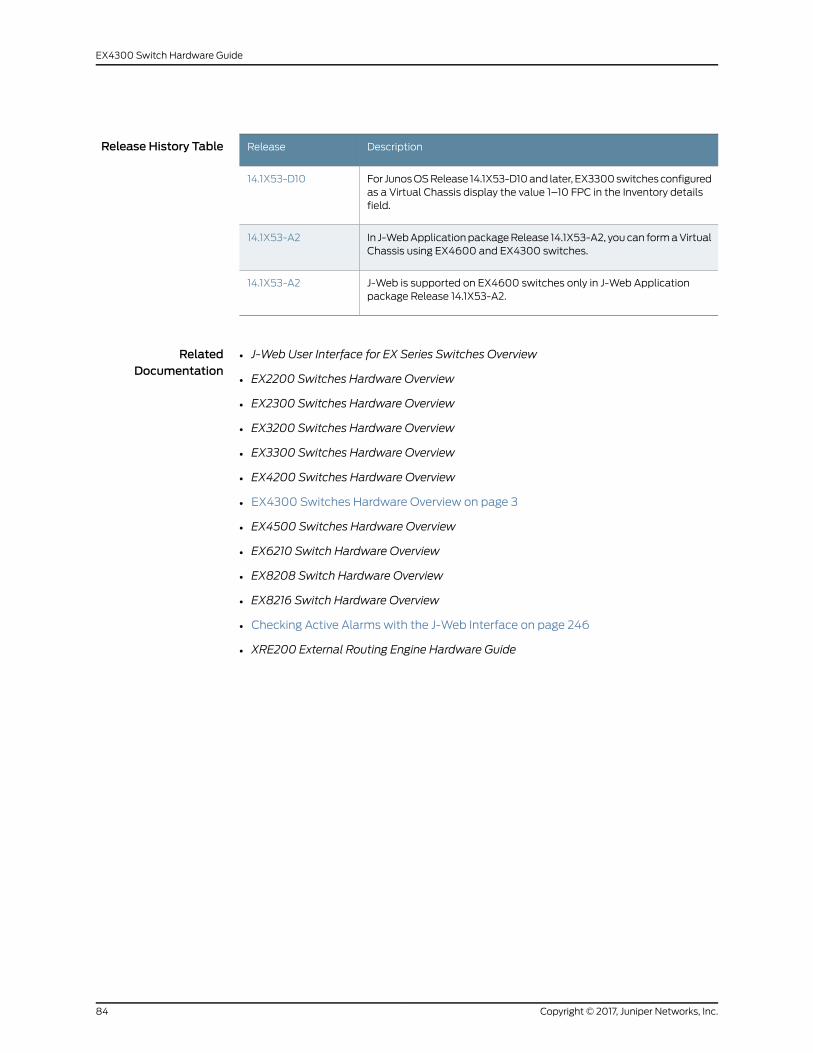
Release History Table DescriptionRelease
For JunosOSRelease 14.1X53-D10and later, EX3300switchesconfiguredas a Virtual Chassis display the value 1–10 FPC in the Inventory detailsfield.
14.1X53-D10
In J-WebApplicationpackageRelease 14.1X53-A2, youcan formaVirtualChassis using EX4600 and EX4300 switches.
14.1X53-A2
J-Web is supported on EX4600 switches only in J-Web Applicationpackage Release 14.1X53-A2.
14.1X53-A2
RelatedDocumentation
• J-Web User Interface for EX Series Switches Overview
• EX2200 Switches Hardware Overview
• EX2300 Switches Hardware Overview
• EX3200 Switches Hardware Overview
• EX3300 Switches Hardware Overview
• EX4200 Switches Hardware Overview
• EX4300 Switches Hardware Overview on page 3
• EX4500 Switches Hardware Overview
• EX6210 Switch Hardware Overview
• EX8208 Switch Hardware Overview
• EX8216 Switch Hardware Overview
• Checking Active Alarms with the J-Web Interface on page 246
• XRE200 External Routing Engine Hardware Guide
Copyright © 2017, Juniper Networks, Inc.84
EX4300 Switch Hardware Guide

PART 2
Site Planning, Preparation, andSpecifications
• Preparation Overview on page 87
• Power Specifications and Requirements on page 99
• Transceiver and Cable Specifications on page 109
• Pinout Specifications on page 121
85Copyright © 2017, Juniper Networks, Inc.

Copyright © 2017, Juniper Networks, Inc.86
EX4300 Switch Hardware Guide

CHAPTER 6
Preparation Overview
• Site Preparation Checklist for EX4300 Switches on page 87
• Environmental Requirements and Specifications for EX Series Switches on page 88
• General Site Guidelines on page 92
• Site Electrical Wiring Guidelines on page 93
• Rack Requirements on page 93
• Cabinet Requirements on page 94
• Clearance Requirements for Airflow and Hardware Maintenance for EX4300
Switches on page 95
Site Preparation Checklist for EX4300 Switches
The checklist in Table 57 on page 87 summarizes the tasks you need to performwhen
preparing a site for EX4300 switch installation.
Table 57: Site Preparation Checklist
DatePerformed byFor More InformationItem or Task
Environment
“Environmental Requirements andSpecifications for EX SeriesSwitches” on page 88
Verify that environmental factors such astemperatureandhumiditydonotexceedswitchtolerances.
Power
Measure the distance between external powersources and the switch installation site.
Locate sites for connection of systemgrounding.
• AC Power Supply Specificationsfor EX4300 Switches on page 99
• DC Power Supply SpecificationsforEX4300Switchesonpage 104
Calculate the power consumption andrequirements.
Hardware Configuration
87Copyright © 2017, Juniper Networks, Inc.

Table 57: Site Preparation Checklist (continued)
DatePerformed byFor More InformationItem or Task
“EX4300 Switches HardwareOverview” on page 3
Choose the number and types of switches youwant to install.
Rack or Cabinet
• Rack Requirements on page 93
• CabinetRequirementsonpage94
Verify that your rack or cabinet meets theminimum requirements for the installation ofthe switch.
“ClearanceRequirements forAirflowand Hardware Maintenance forEX4300 Switches” on page 95
Plan rackor cabinet location, including requiredspace clearances.
Secure the rack or cabinet to the floor andbuilding structure.
Cables
Acquire cables and connectors:
• Determine the number of cables neededbased on your planned configuration.
• Review themaximum distance allowed foreachcable.Choose the lengthof cablebasedon the distance between the hardwarecomponents being connected.
Plan the cable routing andmanagement.
RelatedDocumentation
General Safety Guidelines andWarnings on page 261•
• General Site Guidelines on page 92
• Installing and Connecting an EX4300 Switch on page 137
• Mounting an EX4300 Switch on page 138
Environmental Requirements and Specifications for EX Series Switches
The switch must be installed in a rack or cabinet housed in a dry, clean, well-ventilated,
and temperature-controlled environment.
Ensure that these environmental guidelines are followed:
• The site must be as dust-free as possible, because dust can clog air intake vents and
filters, reducing the efficiency of the switch cooling system.
• Maintain ambient airflow for normal switch operation. If the airflow is blocked or
restricted, or if the intake air is too warm, the switch might overheat, leading to the
switch temperature monitor shutting down the switch to protect the hardware
components.
Copyright © 2017, Juniper Networks, Inc.88
EX4300 Switch Hardware Guide

Table 58 on page 89 provides the required environmental conditions for normal switch
operation.
Table 58: EX Series Switch Environmental Tolerances
Environment Tolerance
Switch ordevice SeismicTemperatureRelative HumidityAltitude
Complies with Zone 4earthquakerequirements as perGR-63, Issue 4.
Normaloperationensured in thetemperature range 32° F (0°C)through 104° F (40° C) ataltitudes up to 5,000 ft(1,524m).
For informationaboutextendedtemperature SFP transceiverssupportedonEX2200switches,see Pluggable TransceiversSupportedonEX2200Switches.
Normaloperationensured inthe relative humidity range10% through 85%(noncondensing)
No performancedegradation up to5,000 feet(1524meters)
EX2200-C
Complies with Zone 4earthquakerequirements as perGR-63, Issue 4.
Normaloperationensured in thetemperature range 32° F (0°C)through 113° F (45° C)
Normaloperationensured inthe relative humidity range10% through 85%(noncondensing)
No performancedegradation up to10,000 feet(3048meters)
EX2200(exceptEX2200-Cswitches)
Complies with Zone 4earthquakerequirements as perGR-63, Issue 4.
Normaloperationensured in thetemperature range 32° F (0°C)through 104° F (40° C)
Normaloperationensured inthe relative humidity range10% through 85%(noncondensing)
No performancedegradation up to5,000 feet(1524meters)
EX2300-C
Complies with Zone 4earthquakerequirements as perGR-63, Issue 4.
Normaloperationensured in thetemperature range 32° F (0°C)through 113° F (45° C)
Normaloperationensured inthe relative humidity range10% through 85%(noncondensing)
No performancedegradation up to13,000 feet(3048meters) at104° F (40° C) as perGR-63
EX2300(exceptEX2300-Cswitches)
Complies with Zone 4earthquakerequirements as perGR-63, Issue 4.
Normaloperationensured in thetemperature range 32° F (0°C)through 113° F (45° C)
Normaloperationensured inthe relative humidity range10% through 85%(noncondensing)
No performancedegradation up to10,000 feet(3048meters)
EX3200
Complies with Zone 4earthquakerequirements as perGR-63, Issue 4.
Normaloperationensured in thetemperature range 32° F (0°C)through 113° F (45° C)
Normaloperationensured inthe relative humidity range10% through 85%(noncondensing)
No performancedegradation up to10,000 feet(3048meters)
EX3300
Complies with Zone 4earthquakerequirements as perGR-63, Issue 4.
Normaloperationensured in thetemperature range 32° F (0°C)through 113° F (45° C)
Normaloperationensured inthe relative humidity range10% through 85%(noncondensing)
No performancedegradation up to10,000 feet(3048meters)
EX3400
Complies with Zone 4earthquakerequirements as perGR-63, Issue 4.
Normaloperationensured in thetemperature range 32° F (0°C)through 113° F (45° C)
Normaloperationensured inthe relative humidity range10% through 85%(noncondensing)
No performancedegradation up to10,000 feet(3048meters)
EX4200
89Copyright © 2017, Juniper Networks, Inc.
Chapter 6: Preparation Overview
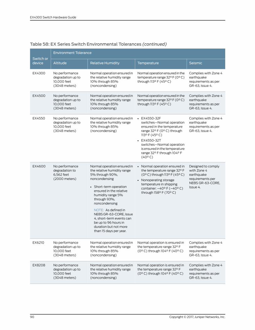
Table 58: EX Series Switch Environmental Tolerances (continued)
Environment Tolerance
Switch ordevice SeismicTemperatureRelative HumidityAltitude
Complies with Zone 4earthquakerequirements as perGR-63, Issue 4.
Normaloperationensured in thetemperature range 32° F (0°C)through 113° F (45° C)
Normaloperationensured inthe relative humidity range10% through 85%(noncondensing)
No performancedegradation up to10,000 feet(3048meters)
EX4300
Complies with Zone 4earthquakerequirements as perGR-63, Issue 4.
Normaloperationensured in thetemperature range 32° F (0°C)through 113° F (45° C)
Normaloperationensured inthe relative humidity range10% through 85%(noncondensing)
No performancedegradation up to10,000 feet(3048meters)
EX4500
Complies with Zone 4earthquakerequirements as perGR-63, Issue 4.
• EX4550-32Fswitches—Normal operationensured in the temperaturerange 32° F (0° C) through113° F (45° C)
• EX4550-32Tswitches—Normal operationisensured in the temperaturerange 32° F through 104° F(40° C)
Normaloperationensured inthe relative humidity range10% through 85%(noncondensing)
No performancedegradation up to10,000 feet(3048meters)
EX4550
Designed to complywith Zone 4earthquakerequirements perNEBS GR-63-CORE,Issue 4.
• Normal operation ensured inthe temperature range 32° F(0°C) through 113° F (45°C)
• Nonoperating storagetemperature in shippingcontainer: –40° F (–40° C)through 158° F (70° C)
Normaloperationensured inthe relative humidity range5% through 90%,noncondensing
• Short-term operationensured in the relativehumidity range 5%through 93%,noncondensing
NOTE: As defined inNEBSGR-63-CORE, Issue4, short-term events canbe up to 96 hours induration but not morethan 15 days per year.
No performancedegradation to6,562 feet(2000meters)
EX4600
Complies with Zone 4earthquakerequirements as perGR-63, Issue 4.
Normal operation is ensured inthe temperature range 32° F(0° C) through 104° F (40° C)
Normaloperationensured inthe relative humidity range10% through 85%(noncondensing)
No performancedegradation up to10,000 feet(3048meters)
EX6210
Complies with Zone 4earthquakerequirements as perGR-63, Issue 4.
Normal operation is ensured inthe temperature range 32° F(0° C) through 104° F (40° C)
Normaloperationensured inthe relative humidity range10% through 85%(noncondensing)
No performancedegradation up to10,000 feet(3048meters)
EX8208
Copyright © 2017, Juniper Networks, Inc.90
EX4300 Switch Hardware Guide
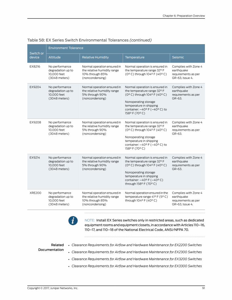
Table 58: EX Series Switch Environmental Tolerances (continued)
Environment Tolerance
Switch ordevice SeismicTemperatureRelative HumidityAltitude
Complies with Zone 4earthquakerequirements as perGR-63, Issue 4.
Normal operation is ensured inthe temperature range 32° F(0° C) through 104° F (40° C)
Normaloperationensured inthe relative humidity range10% through 85%(noncondensing)
No performancedegradation up to10,000 feet(3048meters)
EX8216
Complies with Zone 4earthquakerequirements as perGR-63.
Normal operation is ensured inthe temperature range 32° F(0° C) through 104° F (40° C)
Nonoperating storagetemperature in shippingcontainer: –40° F (–40° C) to158° F (70° C)
Normaloperationensured inthe relative humidity range5% through 90%(noncondensing)
No performancedegradation up to10,000 feet(3048meters)
EX9204
Complies with Zone 4earthquakerequirements as perGR-63.
Normal operation is ensured inthe temperature range 32° F(0° C) through 104° F (40° C)
Nonoperating storagetemperature in shippingcontainer: –40° F (–40° C) to158° F (70° C)
Normaloperationensured inthe relative humidity range5% through 90%(noncondensing)
No performancedegradation up to10,000 feet(3048meters)
EX9208
Complies with Zone 4earthquakerequirements as perGR-63.
Normal operation is ensured inthe temperature range 32° F(0° C) through 104° F (40° C)
Nonoperating storagetemperature in shippingcontainer: –40° F (–40° C)through 158° F (70° C)
Normaloperationensured inthe relative humidity range5% through 90%(noncondensing)
No performancedegradation up to10,000 feet(3048meters)
EX9214
Complies with Zone 4earthquakerequirements as perGR-63, Issue 4.
Normaloperationensured in thetemperature range 41° F (5° C)through 104° F (40° C)
Normaloperationensured inthe relative humidity range10% through 85%(noncondensing)
No performancedegradation up to10,000 feet(3048meters)
XRE200
NOTE: Install EX Series switches only in restricted areas, such as dedicatedequipment roomsandequipmentclosets, inaccordancewithArticles 110–16,110–17, and 110–18 of the National Electrical Code, ANSI/NFPA 70.
RelatedDocumentation
Clearance Requirements for Airflow and Hardware Maintenance for EX2200 Switches•
• Clearance Requirements for Airflow and Hardware Maintenance for EX2300 Switches
• Clearance Requirements for Airflow and Hardware Maintenance for EX3200 Switches
• Clearance Requirements for Airflow and Hardware Maintenance for EX3300 Switches
91Copyright © 2017, Juniper Networks, Inc.
Chapter 6: Preparation Overview

• Clearance Requirements for Airflow and Hardware Maintenance for EX3400 Switches
• Clearance Requirements for Airflow and Hardware Maintenance for EX4200 Switches
• Clearance Requirements for Airflow andHardwareMaintenance for EX4300Switches
on page 95
• Clearance Requirements for Airflow and Hardware Maintenance for an EX4600 Switch
• Clearance Requirements for Airflow and Hardware Maintenance for an EX Series
Redundant Power System
• Clearance Requirements for Airflow and Hardware Maintenance for EX4500 Switches
• Clearance Requirements for Airflow and Hardware Maintenance for EX4550 Switches
• Clearance Requirements for Airflow and Hardware Maintenance for an EX6210 Switch
• Clearance Requirements for Airflow and Hardware Maintenance for an EX8208 Switch
• Clearance Requirements for Airflow and Hardware Maintenance for an EX8216 Switch
• Clearance Requirements for Airflow and Hardware Maintenance for an EX9204 Switch
• Clearance Requirements for Airflow and Hardware Maintenance for an EX9208 Switch
• Clearance Requirements for Airflow and Hardware Maintenance for an EX9214 Switch
General Site Guidelines
Efficient device operation requires proper site planning andmaintenance and proper
layout of the equipment, rack or cabinet (if used), and wiring closet.
To plan and create an acceptable operating environment for your device and prevent
environmentally caused equipment failures:
• Keep the area around the chassis free from dust and conductive material, such as
metal flakes.
• Followprescribedairflowguidelines toensure that thecoolingsystemfunctionsproperly
and that exhaust from other equipment does not blow into the intake vents of the
device.
• Follow the prescribed electrostatic discharge (ESD) prevention procedures to prevent
damaging the equipment. Static discharge can cause components to fail completely
or intermittently over time.
• Install the device in a secure area, so that only authorized personnel can access the
device.
RelatedDocumentation
Prevention of Electrostatic Discharge Damage on page 291•
Copyright © 2017, Juniper Networks, Inc.92
EX4300 Switch Hardware Guide

Site ElectricalWiring Guidelines
Table59onpage93describes the factors youmust considerwhileplanning theelectrical
wiring at your site.
WARNING: It is particularly important to provide a properly grounded andshielded environment and to use electrical surge-suppression devices.
Table 59: Site ElectricalWiring Guidelines
GuidelinesSiteWiring Factor
If your site experiences any of the following problems, consult experts in electrical surgesuppression and shielding:
• Improperly installed wires cause radio frequency interference (RFI).
• Damage from lightning strikes occurs when wires exceed recommended distances or passbetween buildings.
• Electromagnetic pulses (EMPs) caused by lightning damage unshielded conductors andelectronic devices.
Signaling limitations
To reduce or eliminate RFI from your site wiring, do the following:
• Use a twisted-pair cable with a good distribution of grounding conductors.
• If you must exceed the recommended distances, use a high-quality twisted-pair cable withone ground conductor for each data signal when applicable.
Radio frequencyinterference
If your site is susceptible toproblemswith electromagnetic compatibility (EMC), particularly fromlightning or radio transmitters, seek expert advice.
Some of the problems caused by strong sources of electromagnetic interference (EMI) are:
• Destruction of the signal drivers and receivers in the device
• Electrical hazards as a result of power surges conducted over the lines into the equipment
Electromagneticcompatibility
RelatedDocumentation
General Safety Guidelines andWarnings on page 261•
• General Electrical Safety Guidelines andWarnings on page 289
• Prevention of Electrostatic Discharge Damage on page 291
Rack Requirements
You canmount the device on two-post racks or four-post racks.
Rack requirements consist of:
• Rack type
• Mounting bracket hole spacing
93Copyright © 2017, Juniper Networks, Inc.
Chapter 6: Preparation Overview

• Rack size and strength
• Rack connection to the building structure
Table 60 on page 94 provides the rack requirements and specifications.
Table 60: Rack Requirements and Specifications
GuidelinesRack Requirement
You canmount the device on a rack that provides bracket holes or hole patterns spacedat 1 U (1.75 in. or 4.45 cm) increments andmeets the size and strength requirements tosupport the weight.
A U is the standard rack unit defined by the Electronics Industry Association.
Rack type
The holes in the mounting brackets are spaced at 1 U (1.75 in. or 4.45 cm), so that thedevice can bemounted in any rack that provides holes spaced at that distance.
Mounting bracket hole spacing
• Ensure that the rack complies with the size and strength standards of a 19-in. rack asdefined by the Electronics Industry Association.
• Ensure that the rack rails are spaced widely enough to accommodate the externaldimensions of the device chassis. The outer edges of the front-mounting bracketsextend the width of the chassis to 19 in. (48.2 cm).
• The rack must be strong enough to support the weight of the device.
• Ensure that the spacing of rails and adjacent racks provides for proper clearancearound the device and rack.
Rack size and strength
• Secure the rack to the building structure.
• If earthquakes are a possibility in your geographical area, secure the rack to the floor.
• Secure the rack to the ceiling brackets as well as wall or floor brackets for maximumstability.
Rackconnection tobuildingstructure
RelatedDocumentation
Rack-Mounting and Cabinet-MountingWarnings on page 272•
Cabinet Requirements
You canmount the device in a cabinet that contains a 19-in. rack.
Cabinet requirements consist of:
• Cabinet size
• Clearance requirements
• Cabinet airflow requirements
Table 61 on page 95 provides the cabinet requirements and specifications.
Copyright © 2017, Juniper Networks, Inc.94
EX4300 Switch Hardware Guide
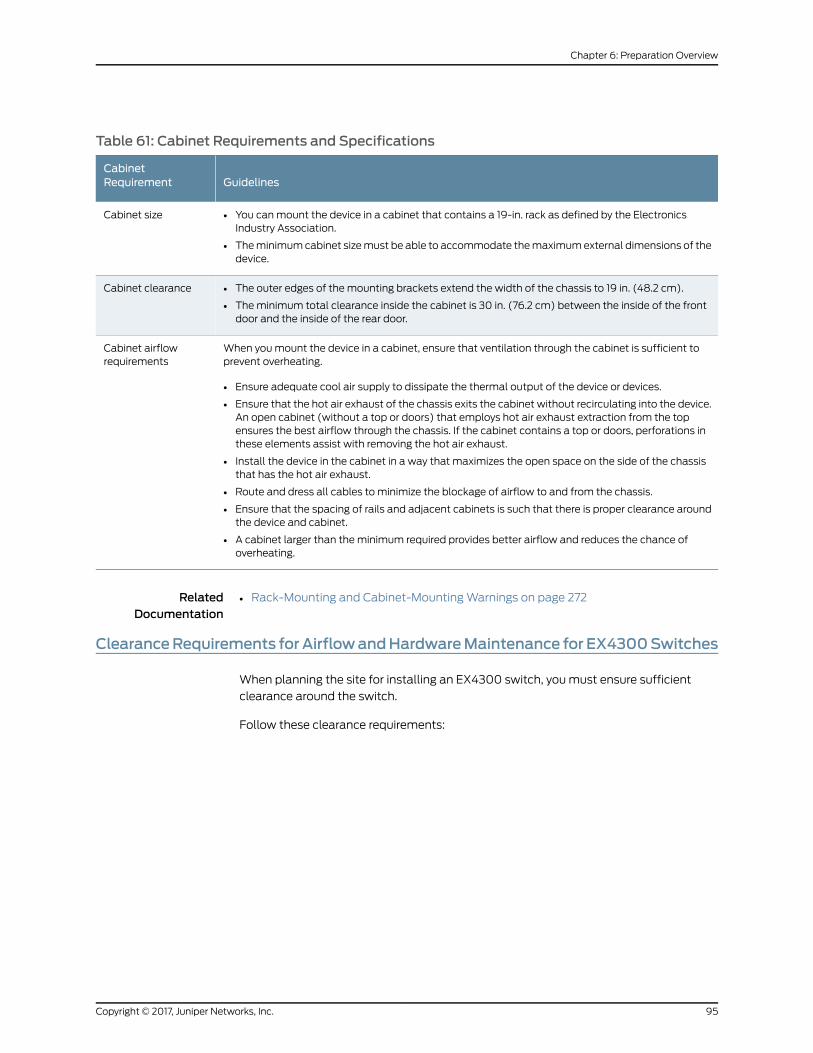
Table 61: Cabinet Requirements and Specifications
GuidelinesCabinetRequirement
• You canmount the device in a cabinet that contains a 19-in. rack as defined by the ElectronicsIndustry Association.
• Theminimumcabinet sizemust be able to accommodate themaximumexternal dimensions of thedevice.
Cabinet size
• The outer edges of the mounting brackets extend the width of the chassis to 19 in. (48.2 cm).
• Theminimum total clearance inside the cabinet is 30 in. (76.2 cm) between the inside of the frontdoor and the inside of the rear door.
Cabinet clearance
When youmount the device in a cabinet, ensure that ventilation through the cabinet is sufficient toprevent overheating.
• Ensure adequate cool air supply to dissipate the thermal output of the device or devices.
• Ensure that the hot air exhaust of the chassis exits the cabinet without recirculating into the device.An open cabinet (without a top or doors) that employs hot air exhaust extraction from the topensures the best airflow through the chassis. If the cabinet contains a top or doors, perforations inthese elements assist with removing the hot air exhaust.
• Install the device in the cabinet in a way that maximizes the open space on the side of the chassisthat has the hot air exhaust.
• Route and dress all cables to minimize the blockage of airflow to and from the chassis.
• Ensure that the spacing of rails and adjacent cabinets is such that there is proper clearance aroundthe device and cabinet.
• A cabinet larger than theminimum required provides better airflow and reduces the chance ofoverheating.
Cabinet airflowrequirements
RelatedDocumentation
Rack-Mounting and Cabinet-MountingWarnings on page 272•
ClearanceRequirements forAirflowandHardwareMaintenance for EX4300Switches
When planning the site for installing an EX4300 switch, youmust ensure sufficient
clearance around the switch.
Follow these clearance requirements:
95Copyright © 2017, Juniper Networks, Inc.
Chapter 6: Preparation Overview
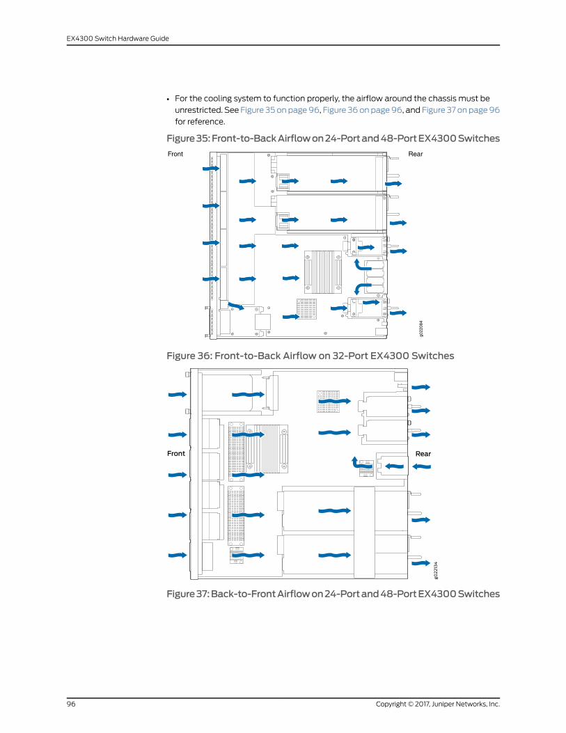
• For the cooling system to function properly, the airflow around the chassis must be
unrestricted. See Figure 35 on page96, Figure 36 onpage96, and Figure 37 on page96
for reference.
Figure35:Front-to-BackAirflowon24-Portand48-PortEX4300Switches
Front Rear
g022
084
Figure 36: Front-to-Back Airflow on 32-Port EX4300 Switches
Figure37:Back-to-FrontAirflowon24-Portand48-PortEX4300Switches
Copyright © 2017, Juniper Networks, Inc.96
EX4300 Switch Hardware Guide
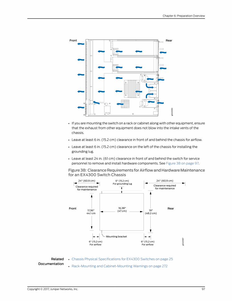
• If you aremounting the switch on a rack or cabinet alongwith other equipment, ensure
that the exhaust from other equipment does not blow into the intake vents of the
chassis.
• Leave at least 6 in. (15.2 cm) clearance in front of and behind the chassis for airflow.
• Leave at least 6 in. (15.2 cm) clearance on the left of the chassis for installing the
grounding lug.
• Leave at least 24 in. (61 cm) clearance in front of and behind the switch for service
personnel to remove and install hardware components. See Figure 38 on page 97.
Figure38: ClearanceRequirementsforAirflowandHardwareMaintenancefor an EX4300 Switch Chassis
RelatedDocumentation
• Chassis Physical Specifications for EX4300 Switches on page 25
• Rack-Mounting and Cabinet-MountingWarnings on page 272
97Copyright © 2017, Juniper Networks, Inc.
Chapter 6: Preparation Overview

• General Site Guidelines on page 92
• Cooling System and Airflow in an EX4300 Switch on page 43
Copyright © 2017, Juniper Networks, Inc.98
EX4300 Switch Hardware Guide
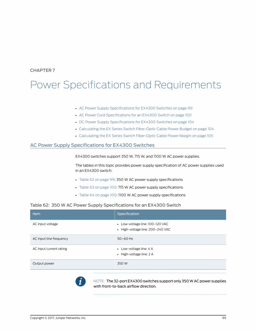
CHAPTER 7
Power Specifications and Requirements
• AC Power Supply Specifications for EX4300 Switches on page 99
• AC Power Cord Specifications for an EX4300 Switch on page 100
• DC Power Supply Specifications for EX4300 Switches on page 104
• Calculating the EX Series Switch Fiber-Optic Cable Power Budget on page 104
• Calculating the EX Series Switch Fiber-Optic Cable Power Margin on page 105
AC Power Supply Specifications for EX4300 Switches
EX4300 switches support 350W, 715W, and 1100WAC power supplies.
The tables in this topic provides power supply specification of AC power supplies used
in an EX4300 switch:
• Table 62 on page 99: 350WAC power supply specifications
• Table 63 on page 100: 715W AC power supply specifications
• Table 64 on page 100: 1100WAC power supply specifications
Table 62: 350WACPower Supply Specifications for an EX4300 Switch
SpecificationItem
• Low-voltage line: 100–120 VAC
• High-voltage line: 200–240 VAC
AC input voltage
50–60 HzAC input line frequency
• Low-voltage line: 4 A
• High-voltage line: 2 A
AC input current rating
350WOutput power
NOTE: The32-portEX4300switches supportonly350WACpower supplieswith front-to-back airflow direction.
99Copyright © 2017, Juniper Networks, Inc.
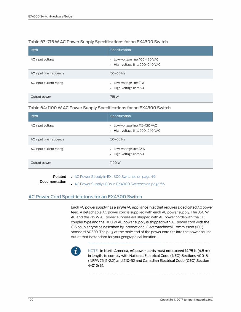
Table 63: 715WAC Power Supply Specifications for an EX4300 Switch
SpecificationItem
• Low-voltage line: 100–120 VAC
• High-voltage line: 200–240 VAC
AC input voltage
50–60 HzAC input line frequency
• Low-voltage line: 11 A
• High-voltage line: 5 A
AC input current rating
715WOutput power
Table 64: 1100WACPower Supply Specifications for an EX4300 Switch
SpecificationItem
• Low-voltage line: 115–120 VAC
• High-voltage line: 200–240 VAC
AC input voltage
50–60 HzAC input line frequency
• Low-voltage line: 12 A
• High-voltage line: 6 A
AC input current rating
1100WOutput power
RelatedDocumentation
AC Power Supply in EX4300 Switches on page 49•
• AC Power Supply LEDs in EX4300 Switches on page 56
AC Power Cord Specifications for an EX4300 Switch
EachACpower supply has a single ACappliance inlet that requires a dedicatedACpower
feed. A detachable AC power cord is supplied with each AC power supply. The 350W
AC and the 715W AC power supplies are shipped with AC power cords with the C13
coupler type and the 1100WAC power supply is shipped with AC power cord with the
C15 coupler type as described by International Electrotechnical Commission (IEC)
standard 60320. The plug at the male end of the power cord fits into the power source
outlet that is standard for your geographical location.
NOTE: In North America, AC power cordsmust not exceed 14.75 ft (4.5 m)in length, to comply with National Electrical Code (NEC) Sections 400-8(NFPA 75, 5-2.2) and 210-52 and Canadian Electrical Code (CEC) Section4-010(3).
Copyright © 2017, Juniper Networks, Inc.100
EX4300 Switch Hardware Guide
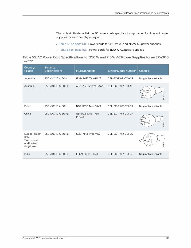
The tables in this topic list theACpower cords specifications provided for different power
supplies for each country or region.
• Table 65 on page 101—Power cords for 350WAC and 715W AC power supplies
• Table 66 on page 103—Power cords for 1100WAC power supplies
Table65:ACPowerCordSpecifications for 350Wand715WACPowerSupplies for anEX4300Switch
GraphicJuniper Model NumberPlug StandardsElectricalSpecifications
Country/Region
No graphic availableCBL-EX-PWR-C13-ARIRAM 2073 Type RA/3250 VAC, 10 A, 50 HzArgentina
CBL-EX-PWR-C13-AUAS/NZS3112TypeSAA/3250 VAC, 10 A, 50 HzAustralia
No graphic availableCBL-EX-PWR-C13-BRNBR 14136 Type BR/3250 VAC, 10 A, 50 HzBrazil
CBL-EX-PWR-C13-CHGB 1002-1996 TypePRC/3
250 VAC, 10 A, 50 HzChina
CBL-EX-PWR-C13-EUCEE (7) VII Type VIIG250 VAC, 10 A, 50 HzEurope(exceptItaly,Switzerland,and UnitedKingdom)
No graphic availableCBL-EX-PWR-C13-INIS 1293 Type IND/3250 VAC, 10 A, 50 HzIndia
101Copyright © 2017, Juniper Networks, Inc.
Chapter 7: Power Specifications and Requirements
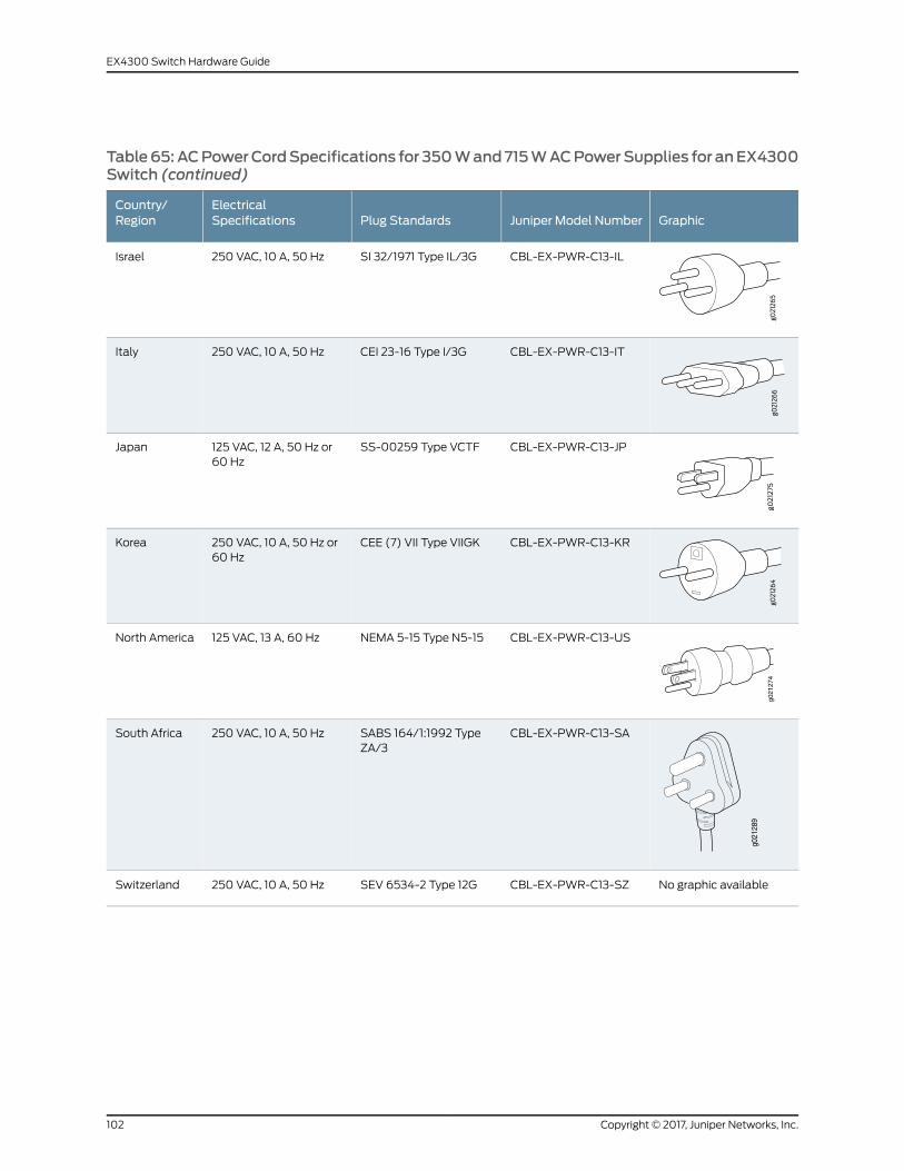
Table65:ACPowerCordSpecifications for 350Wand715WACPowerSupplies for anEX4300Switch (continued)
GraphicJuniper Model NumberPlug StandardsElectricalSpecifications
Country/Region
CBL-EX-PWR-C13-ILSI 32/1971 Type IL/3G250 VAC, 10 A, 50 HzIsrael
CBL-EX-PWR-C13-ITCEI 23-16 Type I/3G250 VAC, 10 A, 50 HzItaly
CBL-EX-PWR-C13-JPSS-00259 Type VCTF125 VAC, 12 A, 50 Hz or60 Hz
Japan
CBL-EX-PWR-C13-KRCEE (7) VII Type VIIGK250 VAC, 10 A, 50 Hz or60 Hz
Korea
g021
274
CBL-EX-PWR-C13-USNEMA 5-15 Type N5-15125 VAC, 13 A, 60 HzNorth America
g021
289
CBL-EX-PWR-C13-SASABS 164/1:1992 TypeZA/3
250 VAC, 10 A, 50 HzSouth Africa
No graphic availableCBL-EX-PWR-C13-SZSEV 6534-2 Type 12G250 VAC, 10 A, 50 HzSwitzerland
Copyright © 2017, Juniper Networks, Inc.102
EX4300 Switch Hardware Guide

Table65:ACPowerCordSpecifications for 350Wand715WACPowerSupplies for anEX4300Switch (continued)
GraphicJuniper Model NumberPlug StandardsElectricalSpecifications
Country/Region
g021
288
CBL-EX-PWR-C13-TWNEMA5-15PTypeN5-15P125 VAC, 10 A, 50 HzTaiwan
CBL-EX-PWR-C13-UKBS 1363/AType BS89/13250 VAC, 10 A, 50 HzUnitedKingdom
Table 66: AC Power Cord Specifications for 1100WACPower Supplies for an EX4300 Switch
Juniper Model NumberPlug StandardsElectrical SpecificationsCountry/Region
CBL-PWR-C15M-HITEMP-ARIRAM 2073 Type RA/3250 VAC, 10 A, 50 HzArgentina
CBL-PWR-C15M-HITEMP-AUAS/NZZS3112-2000TypeSAA/3250 VAC, 10 A, 50 HzAustralia
CBL-PWR-C15M-HITEMP-BRNBR 14136 Type BR/3250 VAC, 10 A, 50 HzBrazil
CBL-PWR-C15M-HITEMP-CHGB2099, GB1002 Type PRC/3250 VAC, 10 A, 50 HzChina
CBL-PWR-C15M-HITEMP-EUCEE (7) VII Type VIIG250 VAC, 10 A, 50 HzEurope (exceptItaly, Switzerland,and UnitedKingdom)
CBL-PWR-C15M-HITEMP-ILSI 32 Type IL/3G250 VAC, 10 A, 50 HzIsrael
CBL-PWR-C15M-HITEMP-INSABS 164/1:1992 Type ZA/3250 VAC, 10 A, 50 HzIndia
CBL-PWR-C15M-HITEMP-ITCEI 23-16 Type I/3G250 VAC, 10 A, 50 HzItaly
CBL-PWR-C15M-HITEMP-JPJIS 8303 Type 498GJ125 VAC, 15 A, 50 Hz or 60 HzJapan
CBL-PWR-C15M-HITEMP-KRCEE (7) VII Type VIIG250 VAC, 10 A, 50 HzKorea
CBL-PWR-C15M-HITEMP-SASABS 164/1:1992 Type ZA/3250 VAC, 10 A, 50 HzSouth Africa
CBL-PWR-C15M-HITEMP-USNEMA 5-15 Type N5/15125 VAC, 15 A, 60 HzNorth America
CBL-PWR-C15M-HITEMP-SZSEV 1011 / 6534-2 Type 12G250 VAC, 10 A, 50 HzSwitzerland
CBL-PWR-C15M-HITEMP-UKBS 1363/A Type BS89/13250 VAC, 10 A, 50 HzUnited Kingdom
103Copyright © 2017, Juniper Networks, Inc.
Chapter 7: Power Specifications and Requirements
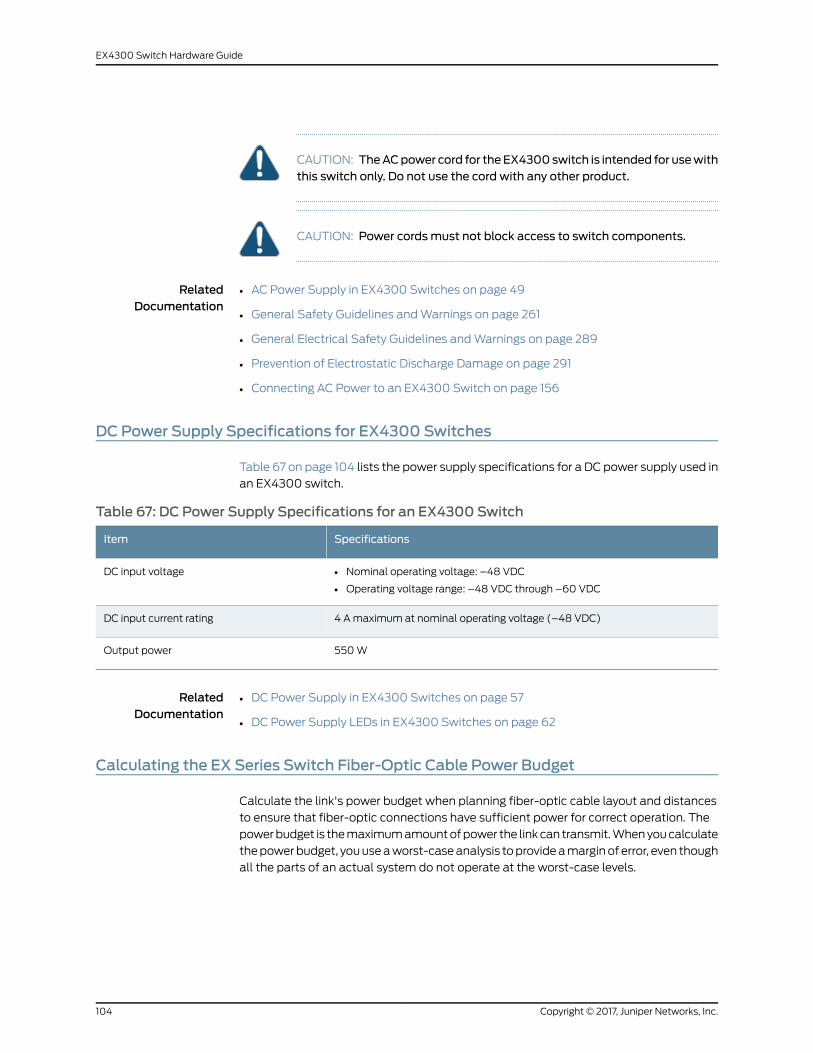
CAUTION: TheACpower cord for theEX4300switch is intended for usewiththis switch only. Do not use the cord with any other product.
CAUTION: Power cordsmust not block access to switch components.
RelatedDocumentation
AC Power Supply in EX4300 Switches on page 49•
• General Safety Guidelines andWarnings on page 261
• General Electrical Safety Guidelines andWarnings on page 289
• Prevention of Electrostatic Discharge Damage on page 291
• Connecting AC Power to an EX4300 Switch on page 156
DC Power Supply Specifications for EX4300 Switches
Table 67 on page 104 lists the power supply specifications for a DC power supply used in
an EX4300 switch.
Table 67: DC Power Supply Specifications for an EX4300 Switch
SpecificationsItem
• Nominal operating voltage: –48 VDC
• Operating voltage range: –48 VDC through –60 VDC
DC input voltage
4 Amaximum at nominal operating voltage (–48 VDC)DC input current rating
550WOutput power
RelatedDocumentation
DC Power Supply in EX4300 Switches on page 57•
• DC Power Supply LEDs in EX4300 Switches on page 62
Calculating the EX Series Switch Fiber-Optic Cable Power Budget
Calculate the link's power budget when planning fiber-optic cable layout and distances
to ensure that fiber-optic connections have sufficient power for correct operation. The
powerbudget is themaximumamountofpower the linkcan transmit.Whenyoucalculate
thepowerbudget, youuseaworst-caseanalysis toprovideamarginof error, even though
all the parts of an actual system do not operate at the worst-case levels.
Copyright © 2017, Juniper Networks, Inc.104
EX4300 Switch Hardware Guide
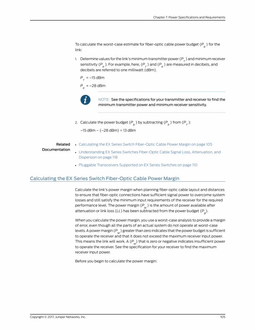
To calculate the worst-case estimate for fiber-optic cable power budget (PB) for the
link:
1. Determinevalues for the link'sminimumtransmitterpower (PT)andminimumreceiver
sensitivity (PR). For example, here, (P
T) and (P
R) are measured in decibels, and
decibels are referred to onemilliwatt (dBm).
PT= –15 dBm
PR= –28 dBm
NOTE: See the specifications for your transmitter and receiver to find theminimum transmitter power andminimum receiver sensitivity.
2. Calculate the power budget (PB) by subtracting (P
R) from (P
T):
–15 dBm – (–28 dBm) = 13 dBm
RelatedDocumentation
Calculating the EX Series Switch Fiber-Optic Cable Power Margin on page 105•
• Understanding EX Series Switches Fiber-Optic Cable Signal Loss, Attenuation, and
Dispersion on page 118
• Pluggable Transceivers Supported on EX Series Switches on page 110
Calculating the EX Series Switch Fiber-Optic Cable Power Margin
Calculate the link's power margin when planning fiber-optic cable layout and distances
to ensure that fiber-optic connections have sufficient signal power to overcome system
losses and still satisfy the minimum input requirements of the receiver for the required
performance level. The power margin (PM) is the amount of power available after
attenuation or link loss (LL) has been subtracted from the power budget (PB).
When you calculate the powermargin, you use aworst-case analysis to provide amargin
of error, even though all the parts of an actual system do not operate at worst-case
levels. Apowermargin (PM) greater than zero indicates that thepowerbudget is sufficient
to operate the receiver and that it does not exceed themaximum receiver input power.
This means the link will work. A (PM) that is zero or negative indicates insufficient power
to operate the receiver. See the specification for your receiver to find the maximum
receiver input power.
Before you begin to calculate the power margin:
105Copyright © 2017, Juniper Networks, Inc.
Chapter 7: Power Specifications and Requirements

• Calculate the power budget. See “Calculating the EX Series Switch Fiber-Optic Cable
Power Budget” on page 104.
To calculate the worst-case estimate for the power margin (PM) for the link:
1. Determine the maximum value for link loss (LL) by adding estimated values for
applicable link-loss factors—for example, use the sample values for various factors
as provided in Table 68 on page 106 (here, the link is 2 km long andmultimode, and
the (PB) is 13 dBm):
Table 68: Estimated Values for Factors Causing Link Loss
Sample (LL) Calculation ValuesEstimated Link-Loss ValueLink-Loss Factor
• 0.5 dBm
• 0 dBm
• Multimode—0.5 dBm
• Single mode—None
Higher-order mode losses (HOL)
• 0 dBm
• 0 dBm
• Multimode—None, if product ofbandwidth and distance is less than500MHz/km
• Single mode—None
Modal and chromatic dispersion
This example assumes 5 connectors.Loss for 5 connectors:
(5) * (0.5 dBm) = 2.5 dBm
0.5 dBmConnector
Thisexampleassumes2splices. Loss fortwo splices:
(2) * (0.5 dBm) = 1 dBm
0.5 dBmSplice
This example assumes the link is 2 kmlong. Fiber attenuation for 2 km:
• (2 km) * (1.0 dBm/km) = 2 dBm
• (2 km) * (0.5 dBm/km) = 1 dBm
• Multimode—1 dBm/km
• Single mode—0.5 dBm/km
Fiber attenuation
1 dBm1 dBmClock Recovery Module (CRM)
NOTE: For information about the actual amount of signal loss caused byequipment and other factors, see your vendor documentation for thatequipment.
2. Calculate the (PM) by subtracting (LL) from (P
B):
PB– LL = P
M
(13 dBm) – (0.5 dBm [HOL]) – ((5) * (0.5 dBm)) – ((2) * (0.5 dBm)) – ((2 km) *
(1.0 dBm/km)) – (1 dB [CRM]) = PM
13 dBm – 0.5 dBm – 2.5 dBm – 1 dBm – 2 dBm – 1 dBm = PM
Copyright © 2017, Juniper Networks, Inc.106
EX4300 Switch Hardware Guide

PM= 6 dBm
Thecalculatedpowermargin is greater than zero, indicating that the link has sufficient
power for transmission. Also, the power margin value does not exceed themaximum
receiver input power. Refer to the specification for your receiver to find the maximum
receiver input power.
RelatedDocumentation
• Calculating the EX Series Switch Fiber-Optic Cable Power Budget on page 104
• Understanding EX Series Switches Fiber-Optic Cable Signal Loss, Attenuation, and
Dispersion on page 118
• Pluggable Transceivers Supported on EX Series Switches on page 110
107Copyright © 2017, Juniper Networks, Inc.
Chapter 7: Power Specifications and Requirements

Copyright © 2017, Juniper Networks, Inc.108
EX4300 Switch Hardware Guide

CHAPTER 8
Transceiver and Cable Specifications
• Pluggable Transceivers Supported on EX4300 Switches on page 109
• Pluggable Transceivers Supported on EX Series Switches on page 110
• SFP+ Direct Attach Copper Cables for EX Series Switches on page 114
• QSFP+ Direct Attach Copper Cables for EX Series Switches on page 116
• Management Cable Specifications on page 117
• Understanding EX Series Switches Fiber-Optic Cable Signal Loss, Attenuation, and
Dispersion on page 118
Pluggable Transceivers Supported on EX4300 Switches
Optional uplink modules for EX4300 switches support SFP, SFP+, and QSFP+
transceivers. You can find the list of transceivers supported on EX4300 switches and
informationabout those transceivers at theHardwareCompatibilityToolpage forEX4300.
NOTE: We recommend that you use only optical transceivers and opticalconnectors purchased from Juniper Networks with your Juniper Networksdevice.
CAUTION: If you face a problem running a Juniper Networks device that usesa third-partyopticor cable, the JuniperNetworksTechnicalAssistanceCenter(JTAC) can help you diagnose the source of the problem. Your JTAC engineermight recommendthatyoucheckthethird-partyopticorcableandpotentiallyreplace it with an equivalent Juniper Networks optic or cable that is qualifiedfor the device.
The Gigabit Ethernet SFP, SFP+, and QSFP+ transceivers installed in EX4300 switches
support digital optical monitoring (DOM): You can view the diagnostic details for these
transceivers by issuing the operational mode CLI command show interfaces diagnostics
optics.
109Copyright © 2017, Juniper Networks, Inc.

NOTE: The transceivers support DOM even if they are installed in the SFP+uplink module ports or QSFP+ ports configured as Virtual Chassis ports(VCPs).
RelatedDocumentation
EX4300 Switches Hardware Overview on page 3•
• Installing a Transceiver on page 219
• Removing a Transceiver on page 221
Pluggable Transceivers Supported on EX Series Switches
The transceivers for EX Series switches are hot-removable and hot-insertable
field-replaceable units (FRUs): You can remove and replace themwithout powering off
the switch or disrupting switch functions.
NOTE: After you insert a transceiver or after you change themedia-typeconfiguration, wait for 6 seconds for the interface to display the operationalcommands.
NOTE: We recommend that you use only optical transceivers and opticalconnectors purchased from Juniper Networks with your Juniper Networksdevice.
CAUTION: If you face a problem running a Juniper Networks device that usesa third-partyopticor cable, the JuniperNetworksTechnicalAssistanceCenter(JTAC) can help you diagnose the source of the problem. Your JTAC engineermight recommendthatyoucheckthethird-partyopticorcableandpotentiallyreplace it with an equivalent Juniper Networks optic or cable that is qualifiedfor the device.
Copyright © 2017, Juniper Networks, Inc.110
EX4300 Switch Hardware Guide

• EX2200—Uplink ports and dual-purpose uplink ports on the front panel in EX2200
switches support SFP transceivers. You can find the list of transceivers supported on
EX2200 switches and information about those transceivers at the Hardware
Compatibility Tool page for EX2200.
NOTE: EX2200-C switches ensure normal operation in the temperaturerange 30° F (0° C) through 104° F (40° C) at altitudes up to 5,000 ft(1,524m).In the following conditions, use extended temperature range SFPtransceivers when fiber uplinks are used:
• In the temperature range 104° F (40° C) through 113° F (45° C) ataltitudes up to 5,000 ft (1,524m)
• In the temperature range95°F(35°C) through 113°F (45°C)ataltitudesabove 5,000 ft (1,524m) up to 10,000 ft (3,048m)
• EX2300—Uplink ports on the front panel in EX2300 switches support SFP and SFP+
transceivers. You can find the list of transceivers supported on EX2300 switches and
information about those transceivers at the Hardware Compatibility Tool page for
EX2300.
NOTE: EX2300-C switches ensure normal operation in the temperaturerange 32° F (0° C) through 104° F (40° C) at altitudes up to 5,000 ft(1,524m).In the temperature range 104° F (40°C) through 113° F (45°C) at altitudesup to5,000ft (1,524m),useextendedtemperature rangeSFPtransceivers.
TheGigabit Ethernet SFPandSFP+ transceivers installed in EX2300 switches support
digital optical monitoring (DOM): You can view the diagnostic details for these
transceiversby issuing theoperationalmodeCLI command show interfacesdiagnostics
optics.
NOTE: The transceivers support DOM even if they are installed in uplinkports configured as Virtual Chassis ports.
• EX3200—Optional uplink modules for EX3200 switches support SFP, SFP+, or XFP
transceivers. You can find the list of transceivers supported on EX3200 switches and
information about those transceivers at the Hardware Compatibility Tool page for
EX3200.
The Gigabit Ethernet SFP, SFP+, or XFP transceivers installed in EX3200 switches
support digital opticalmonitoring (DOM): You can view thediagnostic details for these
transceiversby issuing theoperationalmodeCLI command show interfacesdiagnostics
optics.
• EX3300—Uplink ports on the front panel in EX3300 switches support SFP and SFP+
transceivers. You can find the list of transceivers supported on EX3300 switches and
111Copyright © 2017, Juniper Networks, Inc.
Chapter 8: Transceiver and Cable Specifications

information about those transceivers at the Hardware Compatibility Tool page for
EX3300.
TheGigabit Ethernet SFPandSFP+ transceivers installed in EX3300 switches support
digital optical monitoring (DOM): you can view the diagnostic details for these
transceiversby issuing theoperationalmodeCLI command show interfacesdiagnostics
optics.
NOTE: The transceivers support DOM even if they are installed in uplinkports configured as Virtual Chassis ports.
• EX3400—UplinkportsonEX3400switchessupportSFP,SFP+,andQSFP+transceivers.
You can find the list of transceivers supported on EX3400 switches and information
about those transceivers at the Hardware Compatibility Tool page for EX3400.
TheGigabit EthernetSFP,SFP+, andQSFP+ transceivers installed inEX3400switches
support digital opticalmonitoring (DOM): You can view thediagnostic details for these
transceiversby issuing theoperationalmodeCLI command show interfacesdiagnostics
optics.
NOTE: The transceivers support DOM even if they are installed in uplinkports configured as Virtual Chassis ports.
• EX4200—Optional uplink modules for EX4200 switches support SFP, SFP+, or XFP
transceivers. You can find the list of transceivers supported on EX4200 switches and
information about those transceivers at the Hardware Compatibility Tool page for
EX4200.
The Gigabit Ethernet SFP, SFP+, or XFP transceivers installed in EX4200 switches
support digital opticalmonitoring (DOM): You can view thediagnostic details for these
transceiversby issuing theoperationalmodeCLI command show interfacesdiagnostics
optics.
NOTE: The transceivers support DOM even if they are installed in uplinkmodule ports configured as Virtual Chassis ports.
• EX4300—Optional uplink modules for EX4300 switches support SFP, SFP+, and
QSFP+transceivers. Youcan find the list of transceivers supportedonEX4300switches
and information about those transceivers at the Hardware Compatibility Tool page for
EX4300.
TheGigabit EthernetSFP, SFP+, andQSFP+ transceivers installed in EX4300switches
support digital opticalmonitoring (DOM): You can view thediagnostic details for these
transceiversby issuing theoperationalmodeCLI command show interfacesdiagnostics
optics.
Copyright © 2017, Juniper Networks, Inc.112
EX4300 Switch Hardware Guide

NOTE: The transceivers supportDOMeven if theyare installed in theSFP+uplink module ports or QSFP+ ports configured as Virtual Chassis ports(VCPs).
• EX4500—UplinkmoduleportsonEX4500switchessupportSFPandSFP+transceivers.
You can find the list of transceivers supported on EX4500 switches and information
about those transceivers at the Hardware Compatibility Tool page for EX4500.
TheGigabit Ethernet SFPandSFP+ transceivers installed in EX4500switches support
digital optical monitoring (DOM): You can view the diagnostic details for these
transceiversby issuing theoperationalmodeCLI command show interfacesdiagnostics
optics.
NOTE: The transceivers support DOM even if they are installed in uplinkmodule ports configured as Virtual Chassis ports.
• EX4550—Uplink module ports on EX4550 switches support SFP, SFP+, and QSFP+
transceivers. You can find the list of transceivers supported on EX4550 switches and
information about those transceivers at the Hardware Compatibility Tool page for
EX4550.
The SFP, SFP+, and QSFP+ transceivers installed in EX4550 switches support digital
optical monitoring (DOM): You can view the diagnostic details for these transceivers
by issuing the operational mode CLI command show interfaces diagnostics optics.
NOTE: The transceivers support DOM even if they are installed in theexpansionmodule ports or SFP+ network ports configured as VirtualChassis ports (VCPs).
• EX4600—The quad small form-factor pluggable plus (QSFP+) ports in EX4600
switches support QSFP+ transceivers, QSFP+direct-attach copper (DAC) cables, and
DAC breakout cables (DACBO). Each QSFP+ port on an EX4600 switch can be
configured to operate as 10-Gigabit Ethernet interface by using a breakout cable or as
a single 40-Gigabit Ethernet interface. The ports on an EX4600 switch are disabled
by default. You enable a port through the CLI. The 24 downlink or access ports of the
EX4600 switch are 10-Gigabit Ethernet. You can find the list of transceivers supported
on EX4600 switches and information about those transceivers at the Hardware
Compatibility Tool page for EX4600.
• EX6200—Uplink ports on the Switch Fabric and Routing Engine (SRE) module and
line cards in EX6200 switches support SFP and SFP+ transceivers. You can find the
list of transceivers supported on EX6200 switches and information about those
transceivers at the Hardware Compatibility Tool page for EX6200.
TheGigabit Ethernet SFPandSFP+ transceivers installed in EX6200switches support
digital optical monitoring (DOM). You can view the diagnostic details for these
113Copyright © 2017, Juniper Networks, Inc.
Chapter 8: Transceiver and Cable Specifications

transceiversby issuing theoperationalmodeCLI command show interfacesdiagnostics
optics.
• EX8200—The line cards on EX8200 switches support SFP and SFP+ transceivers.
• You can find the list of transceivers supported on EX8208 switches and information
about those transceivers at the Hardware Compatibility Tool page for EX8208.
• You can find the list of transceivers supported on EX8216 switches and information
about those transceivers at the Hardware Compatibility Tool page for EX8216.
TheGigabit Ethernet SFPandSFP+ transceivers installed in EX8200switches support
digital optical monitoring (DOM): You can view the diagnostic details for these
transceiversby issuing theoperationalmodeCLI command show interfacesdiagnostics
optics.
• EX9200—The line cards in EX9200 switches support 1-gigabit Ethernet small
form-factor pluggable (SFP), 1-gigabit Fast Ethernet SFP, 10-gigabit small form-factor
pluggable plus (SFP+), 40-gigabit quad small form-factor pluggable plus (QSFP+),
and 100-gigabit C form-factor pluggable (CFP) transceivers.
• You can find the list of transceivers supported on EX9204 switches and information
about those transceivers at the Hardware Compatibility Tool page for EX9204.
• You can find the list of transceivers supported on EX9208 switches and information
about those transceivers at the Hardware Compatibility Tool page for EX9208.
• You can find the list of transceivers supported on EX9214 switches and information
about those transceivers at the Hardware Compatibility Tool page for EX9214.
TheGigabit Ethernet SFP, SFP+, andQSFP+ transceivers and the 100GBASE-LR4CFP
transceivers installed in EX9200 switches support digital optical monitoring (DOM):
You can view the diagnostic details for these transceivers by issuing the operational
mode CLI command show interfaces diagnostics optics.
RelatedDocumentation
Installing a Transceiver on page 219•
• Removing a Transceiver on page 221
• Connecting a Fiber-Optic Cable on page 169
SFP+ Direct Attach Copper Cables for EX Series Switches
Small form-factor pluggable plus transceiver (SFP+) direct attach copper (DAC) cables,
also known as Twinax cables, are suitable for in-rack connections between servers and
switches. Theyare suitable for short distances,making them ideal for highly cost-effective
networking connectivity within a rack and between adjacent racks.
NOTE: We recommend that you use only SFP+ DAC cables purchased fromJuniper Networks with your Juniper Networks device.
Copyright © 2017, Juniper Networks, Inc.114
EX4300 Switch Hardware Guide

CAUTION: If you face a problem running a Juniper Networks device that usesa third-partyopticor cable, the JuniperNetworksTechnicalAssistanceCenter(JTAC) can help you diagnose the source of the problem. Your JTAC engineermight recommendthatyoucheckthethird-partyopticorcableandpotentiallyreplace it with an equivalent Juniper Networks optic or cable that is qualifiedfor the device.
This topic describes:
• Cable Specifications on page 115
• List of DAC Cables Supported on EX Series Switches on page 115
• Standards Supported by These Cables on page 116
Cable Specifications
EX Series switches support SFP+ passive DAC cables. The passive Twinax cable is a
straight cable with no active electronic components. EX Series switches support 1 m,
3 m, 5 m, and 7m long SFP+ passive DAC cables. See Figure 39 on page 115.
Figure 39: SFP+ Direct Attach Copper Cables for EX Series Switches
The cables are hot-removable and hot-insertable: You can remove and replace them
without powering off the switch or disrupting switch functions. A cable comprises a
low-voltage cable assembly that connects directly into two 10-Gigabit Ethernet ports,
one at each end of the cable. The cables use high-performance integrated duplex serial
data links for bidirectional communication and are designed for data rates of up to
10 Gbps.
List of DAC Cables Supported on EX Series Switches
For the list ofDACcables supportedonEXSeries switchesand thespecificationsof these
cables, see:
• EX2300—Hardware Compatibility Tool page for EX2300
• EX3200—Hardware Compatibility Tool page for EX3200
• EX3300—Hardware Compatibility Tool page for EX3300
• EX3400—Hardware Compatibility Tool page for EX3400
• EX4200—Hardware Compatibility Tool page for EX4200
• EX4300—Hardware Compatibility Tool page for EX4300
• EX4500—Hardware Compatibility Tool page for EX4500
115Copyright © 2017, Juniper Networks, Inc.
Chapter 8: Transceiver and Cable Specifications

• EX4550—Hardware Compatibility Tool page for EX4550
• EX4600—Hardware Compatibility Tool page for EX4600
• EX8208—Hardware Compatibility Tool page for EX8208
• EX8216—Hardware Compatibility Tool page for EX8216
Standards Supported by These Cables
The cables comply with the following standards:
• SFPmechanical standard SFF-843—see ftp://ftp.seagate.com/sff/SFF-8431.PDF.
• Electrical interface standard SFF-8432—see ftp://ftp.seagate.com/sff/SFF-8432.PDF.
• SFP+Multi-Source Alliance (MSA) standards
RelatedDocumentation
Pluggable Transceivers Supported on EX Series Switches on page 110•
• Installing a Transceiver on page 219
• Removing a Transceiver on page 221
QSFP+ Direct Attach Copper Cables for EX Series Switches
Quad small form-factor pluggable plus (QSFP+) direct attach copper (DAC) cables are
suitable for in-rack connections between QSFP+ ports on EX3400, EX4300, EX4550,
andEX4600switches. Theyare suitable for short distances,making them ideal for highly
cost-effective networking connectivity within a rack and between adjacent racks.
NOTE: Werecommend that youuseonlyQSFP+DACcablespurchased fromJuniper Networks with your Juniper Networks device.
CAUTION: If you face a problem running a Juniper Networks device that usesa third-partyopticor cable, the JuniperNetworksTechnicalAssistanceCenter(JTAC) can help you diagnose the source of the problem. Your JTAC engineermight recommendthatyoucheckthethird-partyopticorcableandpotentiallyreplace it with an equivalent Juniper Networks optic or cable that is qualifiedfor the device.
This topic describes:
• Cable Specifications on page 117
• DACCablesSupportedonEX3400,EX4300,EX4550,andEX4600Switchesonpage117
Copyright © 2017, Juniper Networks, Inc.116
EX4300 Switch Hardware Guide

Cable Specifications
QSFP+ passive DAC cables are hot-removable and hot-in sertable. A cable consists of
a cable assembly that connects directly into two QSFP+modules, one at each end of
the cable. The cables use integrated duplex serial data links for bidirectional
communication and are designed for data rates up to 40Gbps. Passive DAC cables have
no signal amplification built into the cable assembly. See Figure 40 on page 117.
Figure 40: QSFP+ Direct Attach Copper Cables
DAC Cables Supported on EX3400, EX4300, EX4550, and EX4600 Switches
For the list ofDACcables supportedonEX3400,EX4300,EX4550, andEX4600switches
and the specifications of these cables, see:
• EX3400—Hardware Compatibility Tool page for EX3400
• EX4300—Hardware Compatibility Tool page for EX4300
• EX4550—Hardware Compatibility Tool page for EX4550
• EX4600—Hardware Compatibility Tool page for EX4600
RelatedDocumentation
Installing a Transceiver on page 219•
• Removing a Transceiver on page 221
Management Cable Specifications
Table 69 on page 117 lists the specifications for the cables that connect the console
(CON) andmanagement (MGMT) ports to management devices.
Table 69: Specifications of Cables to Connect toManagement Devices
Additional InformationReceptacleCable SpecificationsPorts
“Connecting a Device to aManagement Console byUsinganRJ-45Connector”onpage 166
RJ-45CAT5e UTP (unshieldedtwisted pair) cable
RJ-45 Console (CON2) port
“Connecting a Device to aNetwork for Out-of-BandManagement” on page 165
––Management (MGMT)Ethernet port (10/100/1000)
––Mini-USB Type-B Console(CON1) port
117Copyright © 2017, Juniper Networks, Inc.
Chapter 8: Transceiver and Cable Specifications

Understanding EX Series Switches Fiber-Optic Cable Signal Loss, Attenuation, andDispersion
To determine the power budget and power margin needed for fiber-optic connections,
you need to understand how signal loss, attenuation, and dispersion affect transmission.
EX Series Switches use various types of network cable, including multimode and
single-mode fiber-optic cable.
• Signal Loss in Multimode and Single-Mode Fiber-Optic Cable on page 118
• Attenuation and Dispersion in Fiber-Optic Cable on page 118
Signal Loss in Multimode and Single-Mode Fiber-Optic Cable
Multimode fiber is large enough in diameter to allow rays of light to reflect internally
(bounce off the walls of the fiber). Interfaces with multimode optics typically use LEDs
as light sources. However, LEDs are not coherent light sources. They spray varying
wavelengths of light into themultimode fiber, which reflects the light at different angles.
Light rays travel in jagged lines through amultimode fiber, causing signal dispersion.
When light traveling in the fiber core radiates into the fiber cladding (layers of lower
refractive indexmaterial in close contact with a core material of higher refractive index),
higher-order mode loss (HOL) occurs. Together, these factors reduce the transmission
distance of multimode fiber compared to that of single-mode fiber.
Single-mode fiber is so small in diameter that rays of light reflect internally through one
layer only. Interfaceswith single-mode optics use lasers as light sources. Lasers generate
a singlewavelength of light, which travels in a straight line through the single-mode fiber.
Compared to multimode fiber, single-mode fiber has a higher bandwidth and can carry
signals for longer distances. It is consequently more expensive.
Exceeding themaximumtransmissiondistancescan result in significant signal loss,which
causesunreliable transmission.For informationabout themaximumtransmissiondistance
andsupportedwavelength range for the typesof single-modeandmultimode fiber-optic
cables that are used on different EX Series switches see “Pluggable Transceivers
Supported on EX Series Switches” on page 110.
Attenuation and Dispersion in Fiber-Optic Cable
Anoptical data link functionscorrectlyprovided thatmodulated light reaching the receiver
has enough power to be demodulated correctly. Attenuation is the reduction in strength
of the light signal during transmission. Passivemedia components such as cables, cable
splices, and connectors cause attenuation. Although attenuation is significantly lower
for optical fiber than for other media, it still occurs in both multimode and single-mode
transmission. An efficient optical data link must transmit enough light to overcome
attenuation.
Dispersion is the spreading of the signal over time. The following two types of dispersion
can affect signal transmission through an optical data link:
• Chromatic dispersion, which is the spreading of the signal over time caused by the
different speeds of light rays.
Copyright © 2017, Juniper Networks, Inc.118
EX4300 Switch Hardware Guide

• Modal dispersion,which is the spreading of the signal over time causedby thedifferent
propagation modes in the fiber.
For multimode transmission, modal dispersion, rather than chromatic dispersion or
attenuation, usually limits the maximum bit rate and link length. For single-mode
transmission,modaldispersion is nota factor.However, at higherbit ratesandover longer
distances, chromatic dispersion limits the maximum link length.
An efficient optical data linkmust have enough light to exceed theminimum power that
the receiver requires to operate within its specifications. In addition, the total dispersion
mustbewithin the limits specified for the typeof link inTelcordiaTechnologiesdocument
GR-253-CORE (Section 4.3) and International Telecommunications Union (ITU)
document G.957.
When chromatic dispersion is at the maximum allowed, its effect can be considered as
a power penalty in the power budget. The optical power budget must allow for the sum
of component attenuation, power penalties (including those from dispersion), and a
safety margin for unexpected losses.
RelatedDocumentation
• Calculating the EX Series Switch Fiber-Optic Cable Power Budget on page 104
• Calculating the EX Series Switch Fiber-Optic Cable Power Margin on page 105
119Copyright © 2017, Juniper Networks, Inc.
Chapter 8: Transceiver and Cable Specifications

Copyright © 2017, Juniper Networks, Inc.120
EX4300 Switch Hardware Guide
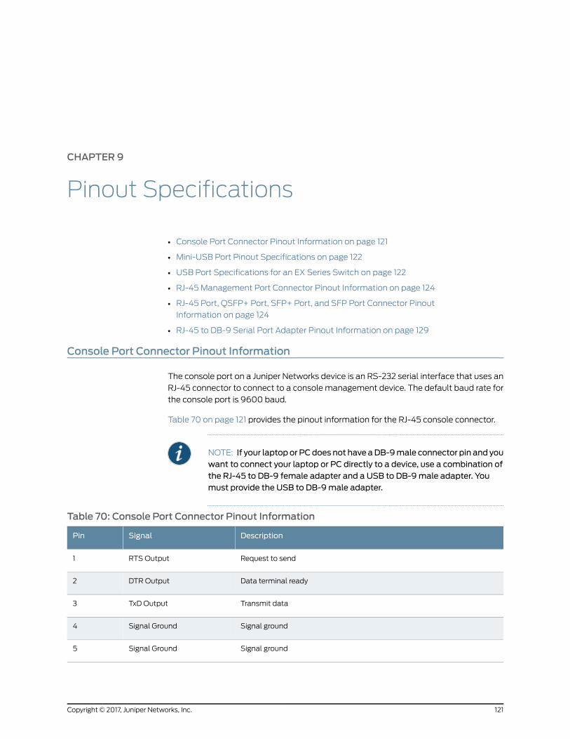
CHAPTER 9
Pinout Specifications
• Console Port Connector Pinout Information on page 121
• Mini-USB Port Pinout Specifications on page 122
• USB Port Specifications for an EX Series Switch on page 122
• RJ-45 Management Port Connector Pinout Information on page 124
• RJ-45 Port, QSFP+ Port, SFP+ Port, and SFP Port Connector Pinout
Information on page 124
• RJ-45 to DB-9 Serial Port Adapter Pinout Information on page 129
Console Port Connector Pinout Information
The console port on a Juniper Networks device is an RS-232 serial interface that uses an
RJ-45 connector to connect to a console management device. The default baud rate for
the console port is 9600 baud.
Table 70 on page 121 provides the pinout information for the RJ-45 console connector.
NOTE: If your laptopor PCdoes not have aDB-9male connector pin and youwant to connect your laptop or PC directly to a device, use a combination ofthe RJ-45 to DB-9 female adapter and a USB to DB-9male adapter. Youmust provide the USB to DB-9male adapter.
Table 70: Console Port Connector Pinout Information
DescriptionSignalPin
Request to sendRTS Output1
Data terminal readyDTR Output2
Transmit dataTxD Output3
Signal groundSignal Ground4
Signal groundSignal Ground5
121Copyright © 2017, Juniper Networks, Inc.
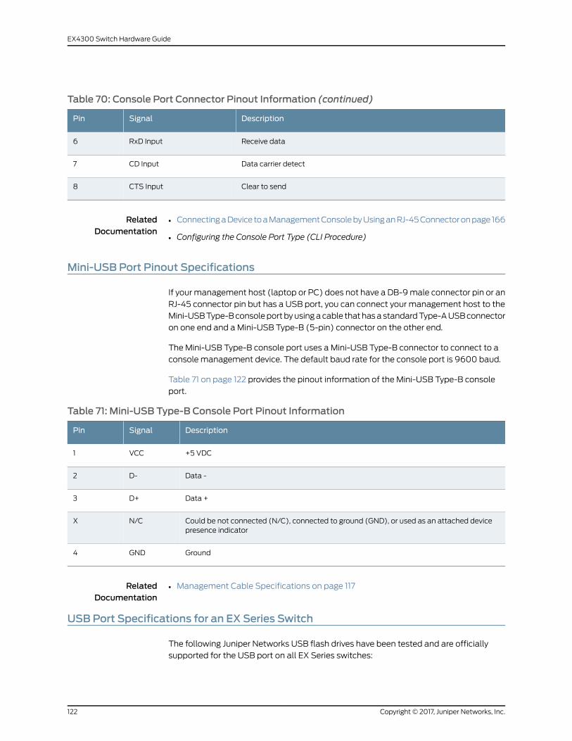
Table 70: Console Port Connector Pinout Information (continued)
DescriptionSignalPin
Receive dataRxD Input6
Data carrier detectCD Input7
Clear to sendCTS Input8
RelatedDocumentation
ConnectingaDevice toaManagementConsolebyUsinganRJ-45Connectoronpage166•
• Configuring the Console Port Type (CLI Procedure)
Mini-USB Port Pinout Specifications
If your management host (laptop or PC) does not have a DB-9male connector pin or an
RJ-45 connector pin but has a USB port, you can connect your management host to the
Mini-USBType-Bconsoleportbyusingacable thathasastandardType-AUSBconnector
on one end and a Mini-USB Type-B (5-pin) connector on the other end.
The Mini-USB Type-B console port uses a Mini-USB Type-B connector to connect to a
console management device. The default baud rate for the console port is 9600 baud.
Table 71 on page 122 provides the pinout information of the Mini-USB Type-B console
port.
Table 71: Mini-USB Type-B Console Port Pinout Information
DescriptionSignalPin
+5 VDCVCC1
Data -D-2
Data +D+3
Could be not connected (N/C), connected to ground (GND), or used as an attached devicepresence indicator
N/CX
GroundGND4
RelatedDocumentation
Management Cable Specifications on page 117•
USB Port Specifications for an EX Series Switch
The following Juniper Networks USB flash drives have been tested and are officially
supported for the USB port on all EX Series switches:
Copyright © 2017, Juniper Networks, Inc.122
EX4300 Switch Hardware Guide

• RE-USB-1G-S
• RE-USB-2G-S
• RE-USB-4G-S
CAUTION: Any USBmemory product not listed as supported for EX Seriesswitches has not been tested by Juniper Networks. The use of anyunsupported USBmemory product could expose your EX Series switch tounpredictablebehavior. JuniperNetworksTechnicalAssistanceCenter (JTAC)can provide only limited support for issues related to unsupported hardware.We strongly recommend that you use only supported USB flash drives.
All USB flash drives used on EX Series switches must have the following features:
• USB 2.0 or later.
• Formatted with a FAT or MS-DOS file system.
• If the switch is running Junos OS Release 9.5 or earlier, the formatting methodmust
use amaster boot record. Microsoft Windows formatting, by default, does not use a
master boot record. See the documentation for your USB flash drive for information
about how your USB flash drive is formatted.
RelatedDocumentation
EX2200 Switches Hardware Overview•
• EX2300 Switches Hardware Overview
• Rear Panel of an EX3200 Switch
• Rear Panel of an EX3300 Switch
• Rear Panel of an EX3400 Switch
• Rear Panel of an EX4200 Switch
• EX4300 Switches Hardware Overview on page 3
• Front Panel of an EX4500 Switch
• Management Panel of an EX4600 Switch
• EX4550 Switches Hardware Overview
• Switch Fabric and Routing Engine (SRE) Module in an EX6200 Switch
• Switch Fabric and Routing Engine (SRE) Module in an EX8208 Switch
• Routing Engine (RE) Module in an EX8216 Switch
• Routing Engine Module in an EX9200 Switch
• Booting an EX Series Switch Using a Software Package Stored on a USB Flash Drive
123Copyright © 2017, Juniper Networks, Inc.
Chapter 9: Pinout Specifications

RJ-45Management Port Connector Pinout Information
Table 72 on page 124 provides the pinout information for the RJ-45 connector for the
management port on Juniper Networks devices.
Table 72: RJ-45Management Port Connector Pinout Information
DescriptionSignalPin
Transmit/receive data pair 1TRP1+1
Transmit/receive data pair 1TRP1-2
Transmit/receive data pair 2TRP2+3
Transmit/receive data pair 3TRP3+4
Transmit/receive data pair 3TRP3-5
Transmit/receive data pair 2TRP2-6
Transmit/receive data pair 4TRP4+7
Transmit/receive data pair 4TRP4-8
RelatedDocumentation
Connecting a Device to a Network for Out-of-Band Management on page 165•
RJ-45 Port, QSFP+ Port, SFP+ Port, and SFP Port Connector Pinout Information
Tables in this topic describe the connector pinout information for the RJ-45, QSFP+,
SFP+, and SFP ports.
• Table 73 on page 124—10/100/1000BASE-T Ethernet network port connector pinout
information
• Table 74 on page 125—SFP network port connector pinout information
• Table 75 on page 126—SFP+ network port connector pinout information
• Table 76 on page 127—QSFP+ network module port connector pinout information
Table 73: 10/100/1000BASE-T Ethernet Network Port Connector Pinout Information
DescriptionSignalPin
Transmit/receive data pair 1
Negative Vport (in PoEmodels)
TRP1+1
Copyright © 2017, Juniper Networks, Inc.124
EX4300 Switch Hardware Guide

Table73: 10/100/1000BASE-TEthernetNetworkPortConnectorPinout Information(continued)
DescriptionSignalPin
Transmit/receive data pair 1
Negative Vport (in PoEmodels)
TRP1-2
Transmit/receive data pair 2
Positive Vport (in PoEmodels)
TRP2+3
Transmit/receive data pair 3TRP3+4
Transmit/receive data pair 3TRP3-5
Transmit/receive data pair 2
Positive Vport (in PoEmodels)
TRP2-6
Transmit/receive data pair 4TRP4+7
Transmit/receive data pair 4TRP4-8
Table 74: SFP Network Port Connector Pinout Information
DescriptionSignalPin
Module transmitter groundVeeT1
Module transmitter faultTX_Fault2
Transmitter disabledTX_Disable3
2-wire serial interface data lineSDA4
2-wire serial interface clockSCL-5
Module absentMOD_ABS6
Rate selectRS7
Receiver loss of signal indicationRX_LOS8
Module receiver groundVeeR9
Module receiver groundVeeR10
Module receiver groundVeeR11
Receiver inverted data outputRD-12
125Copyright © 2017, Juniper Networks, Inc.
Chapter 9: Pinout Specifications
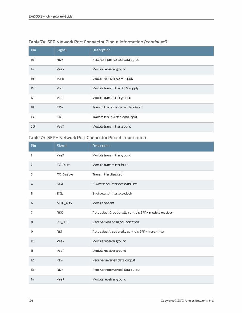
Table 74: SFP Network Port Connector Pinout Information (continued)
DescriptionSignalPin
Receiver noninverted data outputRD+13
Module receiver groundVeeR14
Module receiver 3.3 V supplyVccR15
Module transmitter 3.3 V supplyVccT16
Module transmitter groundVeeT17
Transmitter noninverted data inputTD+18
Transmitter inverted data inputTD-19
Module transmitter groundVeeT20
Table 75: SFP+ Network Port Connector Pinout Information
DescriptionSignalPin
Module transmitter groundVeeT1
Module transmitter faultTX_Fault2
Transmitter disabledTX_Disable3
2-wire serial interface data lineSDA4
2-wire serial interface clockSCL-5
Module absentMOD_ABS6
Rate select 0, optionally controls SFP+module receiverRS07
Receiver loss of signal indicationRX_LOS8
Rate select 1, optionally controls SFP+ transmitterRS19
Module receiver groundVeeR10
Module receiver groundVeeR11
Receiver inverted data outputRD-12
Receiver noninverted data outputRD+13
Module receiver groundVeeR14
Copyright © 2017, Juniper Networks, Inc.126
EX4300 Switch Hardware Guide
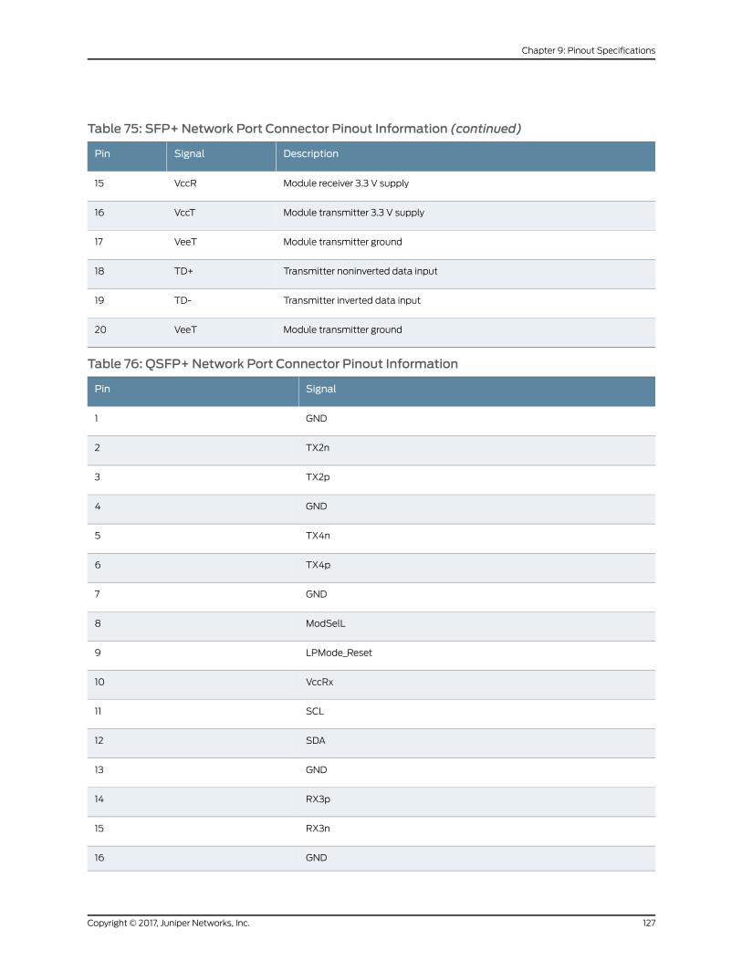
Table 75: SFP+ Network Port Connector Pinout Information (continued)
DescriptionSignalPin
Module receiver 3.3 V supplyVccR15
Module transmitter 3.3 V supplyVccT16
Module transmitter groundVeeT17
Transmitter noninverted data inputTD+18
Transmitter inverted data inputTD-19
Module transmitter groundVeeT20
Table 76: QSFP+Network Port Connector Pinout Information
SignalPin
GND1
TX2n2
TX2p3
GND4
TX4n5
TX4p6
GND7
ModSelL8
LPMode_Reset9
VccRx10
SCL11
SDA12
GND13
RX3p14
RX3n15
GND16
127Copyright © 2017, Juniper Networks, Inc.
Chapter 9: Pinout Specifications
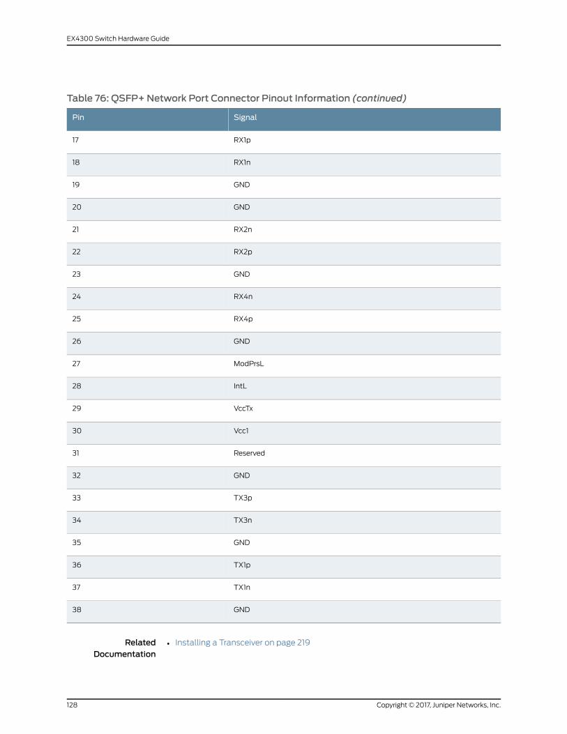
Table 76: QSFP+Network Port Connector Pinout Information (continued)
SignalPin
RX1p17
RX1n18
GND19
GND20
RX2n21
RX2p22
GND23
RX4n24
RX4p25
GND26
ModPrsL27
IntL28
VccTx29
Vcc130
Reserved31
GND32
TX3p33
TX3n34
GND35
TX1p36
TX1n37
GND38
RelatedDocumentation
Installing a Transceiver on page 219•
Copyright © 2017, Juniper Networks, Inc.128
EX4300 Switch Hardware Guide
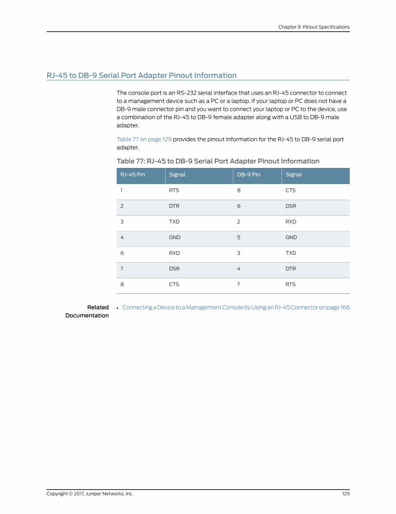
RJ-45 to DB-9 Serial Port Adapter Pinout Information
The console port is an RS-232 serial interface that uses an RJ-45 connector to connect
to amanagement device such as a PC or a laptop. If your laptop or PC does not have a
DB-9male connector pin and you want to connect your laptop or PC to the device, use
a combination of the RJ-45 to DB-9 female adapter along with a USB to DB-9male
adapter.
Table 77 on page 129 provides the pinout information for the RJ-45 to DB-9 serial port
adapter.
Table 77: RJ-45 to DB-9 Serial Port Adapter Pinout Information
SignalDB-9 PinSignalRJ-45 Pin
CTS8RTS1
DSR6DTR2
RXD2TXD3
GND5GND4
TXD3RXD6
DTR4DSR7
RTS7CTS8
RelatedDocumentation
• ConnectingaDevice toaManagementConsolebyUsinganRJ-45Connectoronpage166
129Copyright © 2017, Juniper Networks, Inc.
Chapter 9: Pinout Specifications

Copyright © 2017, Juniper Networks, Inc.130
EX4300 Switch Hardware Guide
PART 3
Initial Installation and Configuration
• Unpacking the Switch on page 133
• Installing the Switch on page 137
• Connecting the Switch to Power on page 149
• Connecting the Switch to the Network on page 165
• Performing Initial Configuration on page 179
131Copyright © 2017, Juniper Networks, Inc.

Copyright © 2017, Juniper Networks, Inc.132
EX4300 Switch Hardware Guide
CHAPTER 10
Unpacking the Switch
• Unpacking an EX4300 Switch on page 133
• Parts Inventory (Packing List) for an EX4300 Switch on page 134
• Registering Products—Mandatory for Validating SLAs on page 135
Unpacking an EX4300 Switch
EX4300switchesareshipped inacardboardcarton, securedwith foampackingmaterial.
The carton has an accessory compartment and contains the quick start instructions.
CAUTION: EX4300 switches aremaximally protected inside the shippingcarton. Do not unpack the switches until you are ready to begin installation.
To unpack the switch:
1. Move the shipping carton to a staging area as close to the installation site as possible,
but where you have enough room to remove the system components.
2. Position the carton so that the arrows are pointing up.
3. Open the top flaps on the shipping carton.
4. Pull out the packing material holding the switch in place.
5. Verify the parts received against the inventory on the label attached to the carton.
See “Parts Inventory (Packing List) for an EX4300 Switch” on page 134.
6. Save the shipping carton and packing materials in case you need to move or ship the
switch later.
RelatedDocumentation
Installing and Connecting an EX4300 Switch on page 137•
• Connecting and Configuring an EX Series Switch (CLI Procedure) on page 187
• Connecting and Configuring an EX Series Switch (J-Web Procedure) on page 190
133Copyright © 2017, Juniper Networks, Inc.

Parts Inventory (Packing List) for an EX4300 Switch
The switch shipment includes a packing list. Check the parts you receive with the switch
against the items on the packing list. The packing list specifies the part number and
provides a description of each part in your order. The parts shipped depend on the switch
model you order. See “EX4300 Switch Models” on page 15 for more information.
If any part on the packing list is missing, contact your customer service representative or
contact Juniper customer care fromwithin the U.S. or Canada by telephone at
1-888-314-5822. For international-dial or direct-dial options in countrieswithout toll-free
numbers, see http://www.juniper.net/support/requesting-support.html .
Table 78 on page 134 lists the parts and their quantities as in the standard packing list for
an EX4300 switch.
Table 78: Inventory of Components Providedwith an EX4300 Switch
QuantityComponent
1Switch
2 preinstalledEX4300-24T, EX4300-24P,EX4300-32F, EX4300-48T,EX4300-48T-AFI, EX4300-48P,EX4300-48T-DC, andEX4300-48T-DC-AFI switches
Fanmodules
Fanmodules for thismodel are not shipped by default; youmustseparately order either two AIROUT (AFO) labelled or two AIR IN(AFI) labelled fanmodules.
EX4300-24T-S, EX4300-24P-S,EX4300-32F-S, EX4300-48T-S, andEX4300-48P-S switches
1 (AC or DC) preinstalledEX4300-24T, EX4300-24P,EX4300-32F, EX4300-48T,EX4300-48T-AFI, EX4300-48P,EX4300-48T-DC, andEX4300-48T-DC-AFI switches
Power supplies
Power supplies for this model are not shipped by default; youmust separately order either AC power supplies or DC powersupplies.
EX4300-24T-S, EX4300-24P-S,EX4300-32F-S, EX4300-48T-S, andEX4300-48P-S switches
1EX4300-24T, EX4300-24P,EX4300-32F, EX4300-48T,EX4300-48T-AFI, EX4300-48P,EX4300-48T-DC, andEX4300-48T-DC-AFI switches
AC power cordappropriate foryourgeographicallocation
AC power cord for these models is not shipped by default; youmust order it separately.
EX4300-24T-S, EX4300-24P-S,EX4300-32F-S, EX4300-48T-S, andEX4300-48P-S switches
• Uplink module slot cover panel: 1
• Power supply cover panel: 1
Cover panels for slots without preinstalled components
Copyright © 2017, Juniper Networks, Inc.134
EX4300 Switch Hardware Guide
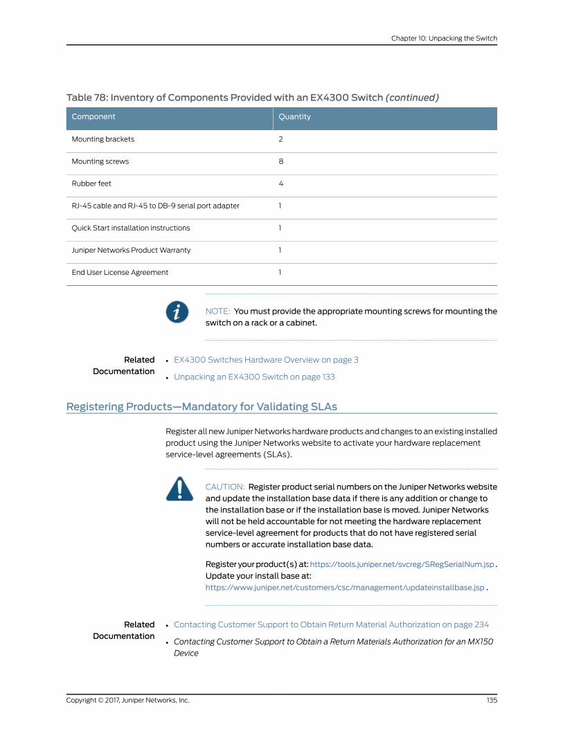
Table 78: Inventory of Components Providedwith an EX4300 Switch (continued)
QuantityComponent
2Mounting brackets
8Mounting screws
4Rubber feet
1RJ-45 cable and RJ-45 to DB-9 serial port adapter
1Quick Start installation instructions
1Juniper Networks ProductWarranty
1End User License Agreement
NOTE: Youmust provide the appropriatemounting screws formounting theswitch on a rack or a cabinet.
RelatedDocumentation
EX4300 Switches Hardware Overview on page 3•
• Unpacking an EX4300 Switch on page 133
Registering Products—Mandatory for Validating SLAs
Register all new JuniperNetworkshardwareproductsandchanges toanexisting installed
product using the Juniper Networks website to activate your hardware replacement
service-level agreements (SLAs).
CAUTION: Register product serial numbers on the Juniper Networkswebsiteand update the installation base data if there is any addition or change tothe installation base or if the installation base is moved. Juniper Networkswill not be held accountable for not meeting the hardware replacementservice-level agreement for products that do not have registered serialnumbers or accurate installation base data.
Register yourproduct(s)at:https://tools.juniper.net/svcreg/SRegSerialNum.jsp .
Update your install base at:https://www.juniper.net/customers/csc/management/updateinstallbase.jsp .
RelatedDocumentation
• Contacting Customer Support to Obtain Return Material Authorization on page 234
• Contacting Customer Support to Obtain a Return Materials Authorization for an MX150
Device
135Copyright © 2017, Juniper Networks, Inc.
Chapter 10: Unpacking the Switch

Copyright © 2017, Juniper Networks, Inc.136
EX4300 Switch Hardware Guide

CHAPTER 11
Installing the Switch
• Installing and Connecting an EX4300 Switch on page 137
• Mounting an EX4300 Switch on page 138
• Mounting an EX4300 Switch on Two Posts of a Rack or Cabinet on page 139
• Mounting an EX4300 Switch on Four Posts of a Rack or Cabinet on page 141
• Mounting an EX4300 Switch in a Recessed Position in a Rack or Cabinet on page 145
• Mounting an EX4300 Switch on aWall on page 145
• Installing and Removing EX4300 Switch Hardware Components on page 147
Installing and Connecting an EX4300 Switch
To install and connect an EX4300 switch:
1. Follow instructions in “Unpacking an EX4300 Switch” on page 133.
2. Install a power supply if it is not preinstalled:
• Installing an AC Power Supply in an EX4300 Switch on page 205
• Installing a DC Power Supply in an EX4300 Switch on page 208
3. Install a fanmodule if it is not preinstalled; see “Installing a FanModule in an EX4300
Switch” on page 201.
4. Mount the switch by following instructions appropriate for your site:
• “Mounting an EX4300 Switch on Two Posts of a Rack or Cabinet” on page 139 (by
using the mounting brackets provided)
• “MountinganEX4300Switch inaRecessedPosition inaRackorCabinet”onpage 145
(by using the 2-in.-recess front brackets from the separately orderable four-post
rack-mount kit)
• “Mounting an EX4300 Switch on Four Posts of a Rack or Cabinet” on page 141 (by
using the separately orderable four-post rack-mount kit)
• “Mounting an EX4300 Switch on aWall” on page 145 (by using the separately
orderable wall-mount kit)
5. Follow instructions in “Connecting Earth Ground to an EX Series Switch” on page 149.
137Copyright © 2017, Juniper Networks, Inc.

6. Follow instructions for connecting power as appropriate for your site:
• Connecting AC Power to an EX4300 Switch on page 156
• Connecting DC Power to an EX4300 Switch on page 159
7. Register your product by following instructions in “Registering Products—Mandatory
for Validating SLAs” on page 135.
8. Perform initial configuration of the switch by following the instructions in “Connecting
andConfiguring an EXSeries Switch (CLI Procedure)” on page 187 or “Connecting and
Configuring an EX Series Switch (J-Web Procedure)” on page 190.
9. Set the switch’s management options by following the instructions in:
• Connecting a Device to a Network for Out-of-Band Management on page 165
• Connecting a Device to a Management Console by Using an RJ-45 Connector on
page 166
• Connecting an EX Series Switch to a Management Console by Using the Mini-USB
Type-B Console Port on page 167
RelatedDocumentation
Rack Requirements on page 93•
• Cabinet Requirements on page 94
• Clearance Requirements for Airflow andHardwareMaintenance for EX4300Switches
on page 95
Mounting an EX4300 Switch
You canmount an EX4300 switch:
• Ontwopostsofa 19-in. rackora 19-in. cabinetbyusing themountingbracketsprovided
with the switch.
• On four posts of a 19-in. rack or a 19-in. cabinet by using the separately orderable
four-post rack-mount kit.
• In a position recessed 2 in. from the front of a 19-in. rack or a 19-in. cabinet by using the
2-in.-recess front brackets in the separately orderable four-post rack-mount kit. You
canmount the switch in this recessed position on two-post or four-post racks and
cabinets.
• On a wall by using the separately orderable wall-mount kit.
The holes in the mounting brackets are placed at 1 U (1.75 in. or 4.45 cm) apart so that
the switch can bemounted in any rack or cabinet that provides holes spaced at that
distance.
See the Related Documentation for detailed descriptions of the various rack or cabinet
mounting options.
Copyright © 2017, Juniper Networks, Inc.138
EX4300 Switch Hardware Guide

RelatedDocumentation
Mounting an EX4300 Switch on Two Posts of a Rack or Cabinet on page 139•
• Mounting an EX4300 Switch in a Recessed Position in a Rack or Cabinet on page 145
• Mounting an EX4300 Switch on Four Posts of a Rack or Cabinet on page 141
• Mounting an EX4300 Switch on aWall on page 145
• Connecting Earth Ground to an EX Series Switch on page 149
Mounting an EX4300 Switch on Two Posts of a Rack or Cabinet
You canmount an EX4300 switch on two posts of a 19-in. rack (either a two-post or a
four-post rack) or a 19-in. cabinet by using the mounting brackets provided with the
switch. (The remainder of this topic uses rack to mean rack or cabinet.)
Youcanmount theswitchon fourpostsofa four-post rackbyusing themountingbrackets
provided with the separately orderable four-post rack-mount kit. See “Mounting an
EX4300 Switch on Four Posts of a Rack or Cabinet” on page 141.
NOTE: If you need tomount the switch in a recessed position on two postsof either a two-post rack or a four-post rack, you can use the 2-in.-recessfront-mounting brackets provided in the separately orderable four-postrack-mount kit.
Before mounting the switch on two posts of a rack:
• Verify that the site meets the requirements described in “Site Preparation Checklist
for EX4300 Switches” on page 87.
• Place the rack in its permanent location, allowing adequate clearance for airflow and
maintenance, and secure it to the building structure.
• Read “General Safety Guidelines andWarnings” on page 261, with particular attention
to “Chassis Lifting Guidelines” on page 270.
• Remove the switch from the shipping carton (see “Unpacking an EX4300 Switch” on
page 133).
Ensure that you have the following parts and tools available:
• Phillips (+) screwdriver, number 2 (not provided)
• 2mounting brackets and 8mounting screws (provided in the accessory box shipped
with the switch)
• Screws to secure the chassis to the rack (not provided)
• 2-in.-recess front-mountingbrackets if youwillmount the switch ina recessedposition
(part of the separately orderable four-post rack-mount kit)
• Cover panels for uplink module and power supply slots (provided)
139Copyright © 2017, Juniper Networks, Inc.
Chapter 11: Installing the Switch
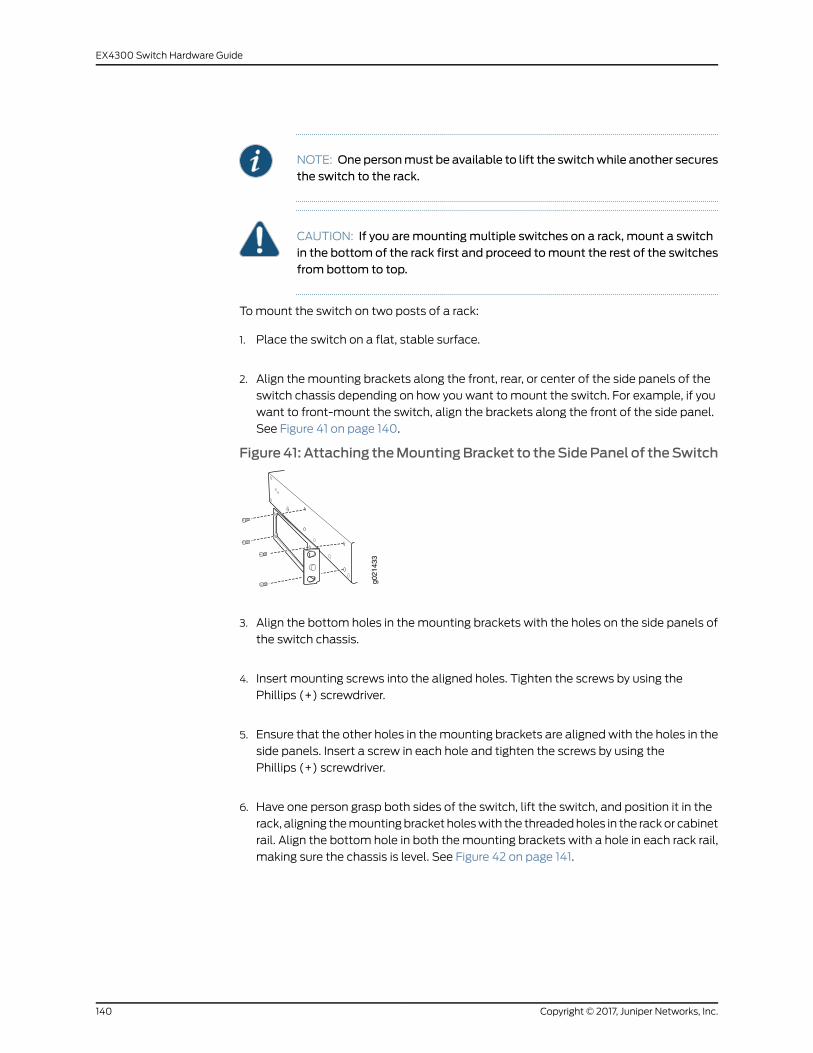
NOTE: Onepersonmust be available to lift the switchwhile another securesthe switch to the rack.
CAUTION: If you aremountingmultiple switches on a rack, mount a switchin the bottom of the rack first and proceed tomount the rest of the switchesfrom bottom to top.
Tomount the switch on two posts of a rack:
1. Place the switch on a flat, stable surface.
2. Align the mounting brackets along the front, rear, or center of the side panels of the
switch chassis depending on how you want to mount the switch. For example, if you
want to front-mount the switch, align the brackets along the front of the side panel.
See Figure 41 on page 140.
Figure41: Attaching theMountingBracket to theSidePanel of theSwitch
g021
433
3. Align the bottom holes in the mounting brackets with the holes on the side panels of
the switch chassis.
4. Insert mounting screws into the aligned holes. Tighten the screws by using the
Phillips (+) screwdriver.
5. Ensure that the other holes in themounting brackets are alignedwith the holes in the
side panels. Insert a screw in each hole and tighten the screws by using the
Phillips (+) screwdriver.
6. Have one person grasp both sides of the switch, lift the switch, and position it in the
rack, aligning themountingbracket holeswith the threadedholes in the rackor cabinet
rail. Align the bottom hole in both themounting brackets with a hole in each rack rail,
making sure the chassis is level. See Figure 42 on page 141.
Copyright © 2017, Juniper Networks, Inc.140
EX4300 Switch Hardware Guide
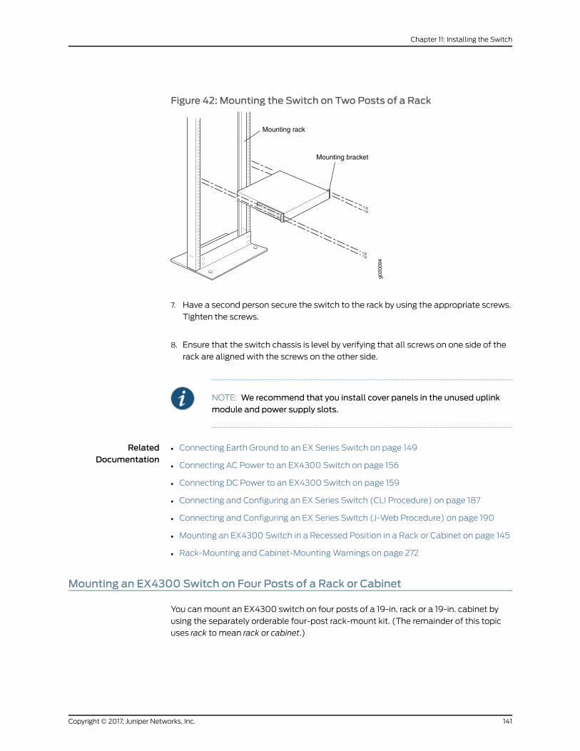
Figure 42: Mounting the Switch on Two Posts of a Rack
g020
094
Mounting rack
Mounting bracket
7. Have a second person secure the switch to the rack by using the appropriate screws.
Tighten the screws.
8. Ensure that the switch chassis is level by verifying that all screws on one side of the
rack are aligned with the screws on the other side.
NOTE: We recommend that you install cover panels in the unused uplinkmodule and power supply slots.
RelatedDocumentation
Connecting Earth Ground to an EX Series Switch on page 149•
• Connecting AC Power to an EX4300 Switch on page 156
• Connecting DC Power to an EX4300 Switch on page 159
• Connecting and Configuring an EX Series Switch (CLI Procedure) on page 187
• Connecting and Configuring an EX Series Switch (J-Web Procedure) on page 190
• Mounting an EX4300 Switch in a Recessed Position in a Rack or Cabinet on page 145
• Rack-Mounting and Cabinet-MountingWarnings on page 272
Mounting an EX4300 Switch on Four Posts of a Rack or Cabinet
You canmount an EX4300 switch on four posts of a 19-in. rack or a 19-in. cabinet by
using the separately orderable four-post rack-mount kit. (The remainder of this topic
uses rack to mean rack or cabinet.)
141Copyright © 2017, Juniper Networks, Inc.
Chapter 11: Installing the Switch

You canmount the switch on two posts of either a two-post rack or a four-post rack by
using themounting brackets providedwith the switch. See “Mounting anEX4300Switch
on Two Posts of a Rack or Cabinet” on page 139.
NOTE: If you need tomount the switch in a recessed position on either atwo-post rackora four-post rack, youcanuse the2-in.-recess front-mountingbrackets provided in the separately orderable four-post rack-mount kit.
NOTE:
To ensure that the protective earthing terminal is accessible through theopening in the rear mounting-blade:
• Ensure that the rack is 27.5 in. (70 cm) through 30.5 in. (77.5 cm) deep ifyou aremounting the switch flush with the rack front on four posts of arack.
• Ensure that the rack is 29.5 in. (75 cm) through 32.5 in. (82.5 cm) deep ifyou will mount the switch 2 in. recessed from the rack front.
Before mounting the switch on four posts of a rack:
• Verify that the site meets the requirements described in “Site Preparation Checklist
for EX4300 Switches” on page 87.
• Place the rack in its permanent location, allowing adequate clearance for airflow and
maintenance, and secure it to the building structure.
• Read “General Safety Guidelines andWarnings” on page 261, with particular attention
to “Chassis Lifting Guidelines” on page 270.
• Remove the switch from the shipping carton (see “Unpacking an EX4300 Switch” on
page 133).
Ensure that you have the following parts and tools available:
• Phillips (+) screwdriver, number 2 (not provided)
• 6 flat-head 4-40 Phillips mounting screws (provided with the four-post rack-mount
kit)
• 12 flat-head4x6-mmPhillipsmountingscrews(providedwith the four-post rack-mount
kit)
• One pair each of flush or 2-in.-recess front-mounting brackets (provided with the
four-post rack-mount kit)
• One pair of side mounting-rails (provided with the four-post rack-mount kit)
• One pair of rear mounting-blades (provided with the four-post rack-mount kit)
• Screws to secure the chassis and the rear mounting-blades to the rack (not provided)
• Cover panels for uplink module and power supply slots (provided)
Copyright © 2017, Juniper Networks, Inc.142
EX4300 Switch Hardware Guide
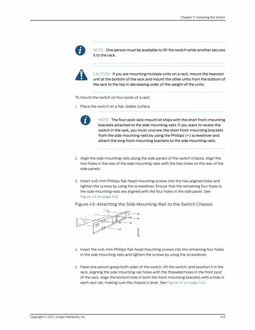
NOTE: Onepersonmust be available to lift the switchwhile another securesit to the rack.
CAUTION: If you aremountingmultiple units on a rack, mount the heaviestunit at the bottom of the rack andmount the other units from the bottom ofthe rack to the top in decreasing order of the weight of the units.
Tomount the switch on four posts of a rack:
1. Place the switch on a flat, stable surface.
NOTE: The four-post rack-mount kit ships with the short front-mountingbrackets attached to the sidemounting-rails. If you want to recess theswitch in the rack, youmust unscrew the short front-mounting bracketsfrom the sidemounting-rails by using the Phillips (+) screwdriver andattach the long front-mounting brackets to the sidemounting-rails.
2. Align the side mounting-rails along the side panels of the switch chassis. Align the
two holes in the rear of the side mounting-rails with the two holes on the rear of the
side panels.
3. Insert 4x6-mmPhillips flat-headmounting screws into the two aligned holes and
tighten the screws by using the screwdriver. Ensure that the remaining four holes in
the side mounting-rails are aligned with the four holes in the side panel. See
Figure 43 on page 143.
Figure 43: Attaching the SideMounting-Rail to the Switch Chassis
g021
432
4. Insert the 4x6-mmPhillips flat-headmounting screws into the remaining four holes
in the side mounting-rails and tighten the screws by using the screwdriver.
5. Have one person grasp both sides of the switch, lift the switch, and position it in the
rack, aligning the side mounting-rail holes with the threaded holes in the front post
of the rack. Align the bottom hole in both the front-mounting brackets with a hole in
each rack rail, making sure the chassis is level. See Figure 44 on page 144.
143Copyright © 2017, Juniper Networks, Inc.
Chapter 11: Installing the Switch
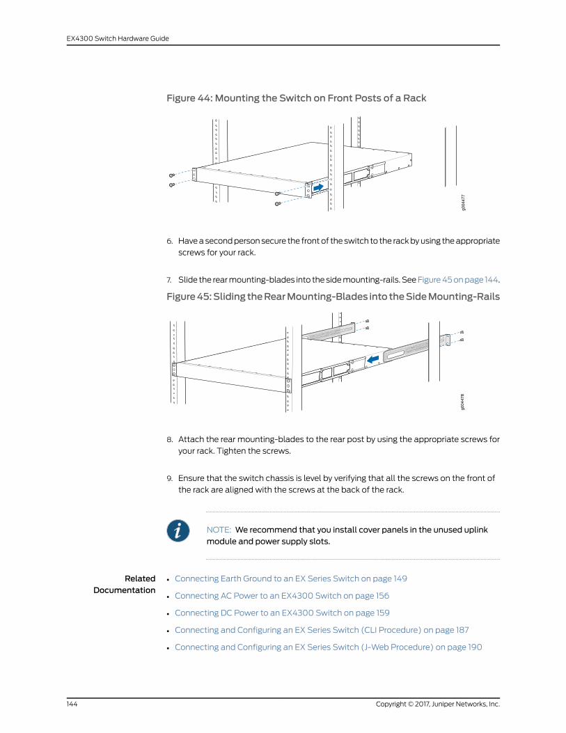
Figure 44: Mounting the Switch on Front Posts of a Rack
g004
477
6. Haveasecondpersonsecure the frontof theswitch to the rackbyusing theappropriate
screws for your rack.
7. Slide the rearmounting-blades into the sidemounting-rails. SeeFigure45onpage 144.
Figure45:Sliding theRearMounting-Blades into theSideMounting-Rails
g004
478
8. Attach the rear mounting-blades to the rear post by using the appropriate screws for
your rack. Tighten the screws.
9. Ensure that the switch chassis is level by verifying that all the screws on the front of
the rack are aligned with the screws at the back of the rack.
NOTE: We recommend that you install cover panels in the unused uplinkmodule and power supply slots.
RelatedDocumentation
Connecting Earth Ground to an EX Series Switch on page 149•
• Connecting AC Power to an EX4300 Switch on page 156
• Connecting DC Power to an EX4300 Switch on page 159
• Connecting and Configuring an EX Series Switch (CLI Procedure) on page 187
• Connecting and Configuring an EX Series Switch (J-Web Procedure) on page 190
Copyright © 2017, Juniper Networks, Inc.144
EX4300 Switch Hardware Guide
• Mounting an EX4300 Switch in a Recessed Position in a Rack or Cabinet on page 145
• Rack-Mounting and Cabinet-MountingWarnings on page 272
Mounting an EX4300 Switch in a Recessed Position in a Rack or Cabinet
YoucanmountanEX4300switch ina recessedpositionon twopostsof either a two-post
rack or a four-post rack such that the switch is recessed inside the rack from the rack
front by 2 inches. Tomount the switch in a recessed position, use the front-mounting
brackets provided in the separately orderable four-post rack-mount kit.
Reasons to mount the switch in a recessed position include:
• Youaremounting theswitch inacabinetand thecabinetdoorsdonotclosecompletely
unless the switch is recessed.
• The switch youaremounting has anuplinkmodulewith transceivers installed in it—the
transceivers in the uplink module ports protrude from the front of the switch.
Tomount the switch in a recessed position, on two-posts or on four-posts, follow the
instructions in “Mounting an EX4300 Switch on Two Posts of a Rack or Cabinet” on
page 139or “MountinganEX4300SwitchonFourPostsofaRackorCabinet”onpage 141.
RelatedDocumentation
Connecting Earth Ground to an EX Series Switch on page 149•
• Rack-Mounting and Cabinet-MountingWarnings on page 272
Mounting an EX4300 Switch on aWall
YoucanmountanEX4300switchonawallbyusing theseparatelyorderablewall-mount
kit.
Before mounting the switch on a wall:
• Verify that the site meets the requirements described in “Site Preparation Checklist
for EX4300 Switches” on page 87.
• Read “General Safety Guidelines andWarnings” on page 261, with particular attention
to “Chassis Lifting Guidelines” on page 270.
• Remove the switch from the shipping carton (see “Unpacking an EX4300 Switch” on
page 133).
Ensure that you have the following parts and tools available:
• Phillips (+) screwdriver, number 2 (not provided)
• 2 wall-mount brackets (provided with the wall-mount kit)
• 12 wall-mount bracket screws (provided with the wall-mount kit)
• 4mounting screws (8-32 x 1.25 in. or M4 x 30mm) (not provided)
145Copyright © 2017, Juniper Networks, Inc.
Chapter 11: Installing the Switch
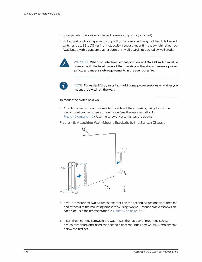
• Cover panels for uplink module and power supply slots (provided)
• Hollowwall anchors capable of supporting the combined weight of two fully loaded
switches, up to33 lb (15kg) (not included)—if youaremounting theswitch in sheetrock
(wall board with a gypsum plaster core) or in wall board not backed by wall studs.
WARNING: Whenmounted in a vertical position, an EX4300 switchmust beoriented with the front panel of the chassis pointing down to ensure properairflow andmeet safety requirements in the event of a fire.
NOTE: For easier lifting, install any additional power supplies only after youmount the switch on the wall.
Tomount the switch on a wall:
1. Attach the wall-mount brackets to the sides of the chassis by using four of the
wall-mount bracket screws on each side (see the representation in
Figure 46 on page 146). Use the screwdriver to tighten the screws.
Figure 46: AttachingWall-Mount Brackets to the Switch Chassisg0
2020
0
1
2
2. If you are mounting two switches together, line the second switch on top of the first
and attach it to the mounting brackets by using two wall-mount bracket screws on
each side (see the representation in Figure 47 on page 147).
3. Insert the mounting screws in the wall. Insert the top pair of mounting screws
474.35mm apart, and insert the second pair of mounting screws 151.81 mm directly
below the first set.
Copyright © 2017, Juniper Networks, Inc.146
EX4300 Switch Hardware Guide
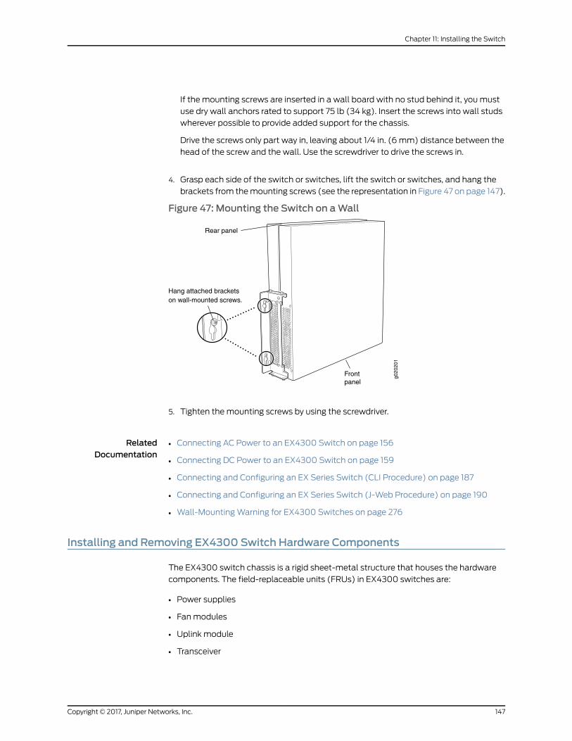
If the mounting screws are inserted in a wall board with no stud behind it, you must
use dry wall anchors rated to support 75 lb (34 kg). Insert the screws into wall studs
wherever possible to provide added support for the chassis.
Drive the screws only part way in, leaving about 1/4 in. (6 mm) distance between the
head of the screw and the wall. Use the screwdriver to drive the screws in.
4. Grasp each side of the switch or switches, lift the switch or switches, and hang the
brackets from themounting screws (see the representation in Figure 47 on page 147).
Figure 47: Mounting the Switch on aWall
Hang attached bracketson wall-mounted screws.
g020
201
Frontpanel
Rear panel
5. Tighten themounting screws by using the screwdriver.
RelatedDocumentation
Connecting AC Power to an EX4300 Switch on page 156•
• Connecting DC Power to an EX4300 Switch on page 159
• Connecting and Configuring an EX Series Switch (CLI Procedure) on page 187
• Connecting and Configuring an EX Series Switch (J-Web Procedure) on page 190
• Wall-MountingWarning for EX4300 Switches on page 276
Installing and Removing EX4300 Switch Hardware Components
The EX4300 switch chassis is a rigid sheet-metal structure that houses the hardware
components. The field-replaceable units (FRUs) in EX4300 switches are:
• Power supplies
• Fanmodules
• Uplink module
• Transceiver
147Copyright © 2017, Juniper Networks, Inc.
Chapter 11: Installing the Switch
The power supply (AC or DC), fan module, uplink module, and transceivers are
hot-removable and hot-insertable: You can remove and replace themwithout powering
off the switch or disrupting switch functions.
NOTE: Youmust remove a fanmodule only for replacement.
See these topics for instructions for installing and removing components:
• Installing an AC Power Supply in an EX4300 Switch on page 205
• Removing an AC Power Supply from an EX4300 Switch on page 207
• Installing a DC Power Supply in an EX4300 Switch on page 208
• Removing a DC Power Supply from an EX4300 Switch on page 210
• Installing a Fan Module in an EX4300 Switch on page 201
• Removing a Fan Module from an EX4300 Switch on page 203
• Installing an Uplink Module in an EX4300 Switch on page 213
• Removing an Uplink Module from an EX4300 Switch on page 215
• Installing a Transceiver on page 219
• Removing a Transceiver on page 221
RelatedDocumentation
• Cooling System and Airflow in an EX4300 Switch on page 43
• AC Power Supply in EX4300 Switches on page 49
• DC Power Supply in EX4300 Switches on page 57
• Uplink Modules in EX4300 Switches on page 31
• Pluggable Transceivers Supported on EX4300 Switches on page 109
Copyright © 2017, Juniper Networks, Inc.148
EX4300 Switch Hardware Guide
CHAPTER 12
Connecting the Switch to Power
• Connecting Earth Ground to an EX Series Switch on page 149
• Connecting AC Power to an EX4300 Switch on page 156
• Connecting DC Power to an EX4300 Switch on page 159
Connecting Earth Ground to an EX Series Switch
To ensure proper operation and to meet safety and electromagnetic interference (EMI)
requirements, youmust connect an EX Series switch to earth ground before you connect
power to the switch. Youmust use the protective earthing terminal on the switch chassis
to connect the switch to earth ground (see Figure 49 on page 155).
WARNING: The switch is installed in a restricted-access location. It has aseparateprotectiveearthingterminalonthechassis thatmustbepermanentlyconnected to earth ground to adequately ground the chassis and protect theoperator from electrical hazards.
CAUTION: Beforeswitch installationbegins, ensure thata licensedelectricianhas attached an appropriate grounding lug to the grounding cable that yousupply. Using a grounding cablewith an incorrectly attached lug candamagethe switch.
This topic describes:
• Parts and Tools Required for Connecting an EX Series Switch to Earth
Ground on page 149
• Special Instructions to FollowBeforeConnectingEarthGround toaSwitchonpage 153
• Connecting Earth Ground to an EX Series Switch on page 155
Parts and Tools Required for Connecting an EX Series Switch to Earth Ground
Table 79 on page 150 lists the earthing terminal location, grounding cable requirements,
grounding lug specifications, screws and washers required, and the screwdriver needed
149Copyright © 2017, Juniper Networks, Inc.
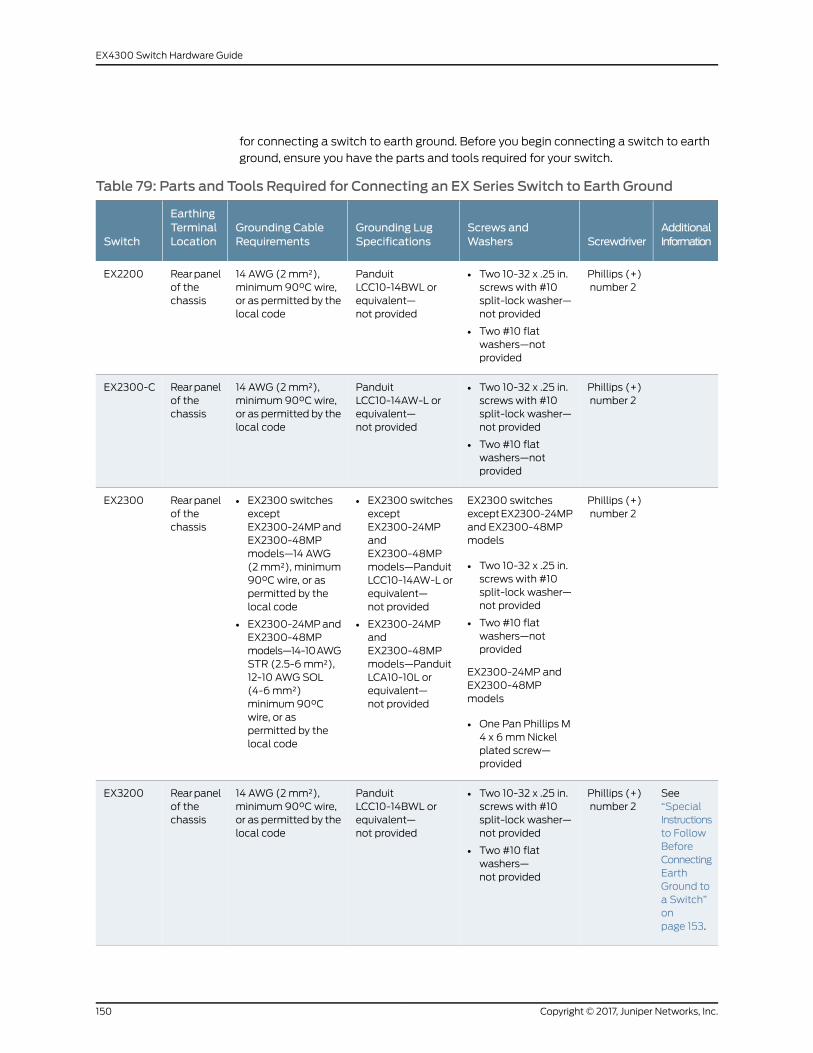
for connecting a switch to earth ground. Before you begin connecting a switch to earth
ground, ensure you have the parts and tools required for your switch.
Table 79: Parts and Tools Required for Connecting an EX Series Switch to Earth Ground
AdditionalInformationScrewdriver
Screws andWashers
Grounding LugSpecifications
Grounding CableRequirements
EarthingTerminalLocationSwitch
Phillips (+)number 2
• Two 10-32 x .25 in.screws with #10split-lock washer—not provided
• Two #10 flatwashers—notprovided
PanduitLCC10-14BWL orequivalent—not provided
14 AWG (2mm²),minimum 90°C wire,or as permitted by thelocal code
Rearpanelof thechassis
EX2200
Phillips (+)number 2
• Two 10-32 x .25 in.screws with #10split-lock washer—not provided
• Two #10 flatwashers—notprovided
PanduitLCC10-14AW-L orequivalent—not provided
14 AWG (2mm²),minimum 90°C wire,or as permitted by thelocal code
Rearpanelof thechassis
EX2300-C
Phillips (+)number 2
EX2300 switchesexceptEX2300-24MPand EX2300-48MPmodels
• Two 10-32 x .25 in.screws with #10split-lock washer—not provided
• Two #10 flatwashers—notprovided
EX2300-24MP andEX2300-48MPmodels
• One Pan Phillips M4 x 6mmNickelplated screw—provided
• EX2300 switchesexceptEX2300-24MPandEX2300-48MPmodels—PanduitLCC10-14AW-L orequivalent—not provided
• EX2300-24MPandEX2300-48MPmodels—PanduitLCA10-10L orequivalent—not provided
• EX2300 switchesexceptEX2300-24MPandEX2300-48MPmodels—14 AWG(2mm²), minimum90°C wire, or aspermitted by thelocal code
• EX2300-24MPandEX2300-48MPmodels—14-10AWGSTR (2.5-6mm²),12-10 AWG SOL(4-6mm²)minimum 90°Cwire, or aspermitted by thelocal code
Rearpanelof thechassis
EX2300
See“SpecialInstructionsto FollowBeforeConnectingEarthGround toa Switch”onpage 153.
Phillips (+)number 2
• Two 10-32 x .25 in.screws with #10split-lock washer—not provided
• Two #10 flatwashers—not provided
PanduitLCC10-14BWL orequivalent—not provided
14 AWG (2mm²),minimum 90°C wire,or as permitted by thelocal code
Rearpanelof thechassis
EX3200
Copyright © 2017, Juniper Networks, Inc.150
EX4300 Switch Hardware Guide
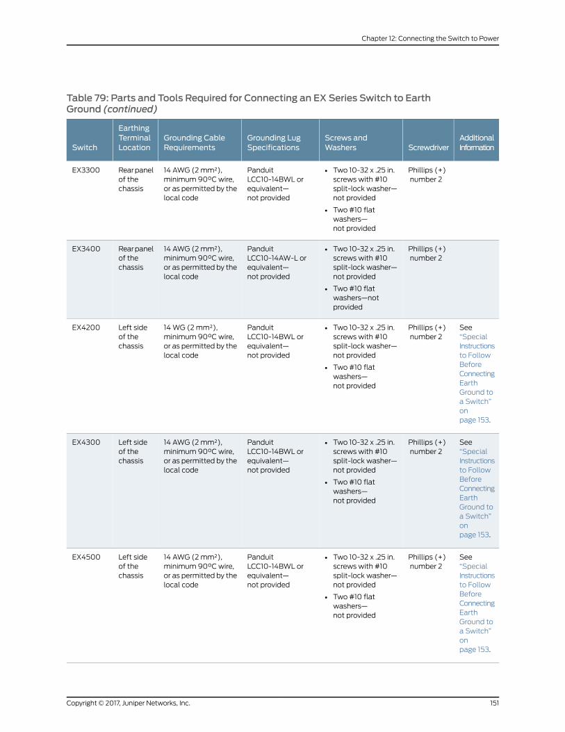
Table 79: Parts and Tools Required for Connecting an EX Series Switch to EarthGround (continued)
AdditionalInformationScrewdriver
Screws andWashers
Grounding LugSpecifications
Grounding CableRequirements
EarthingTerminalLocationSwitch
Phillips (+)number 2
• Two 10-32 x .25 in.screws with #10split-lock washer—not provided
• Two #10 flatwashers—not provided
PanduitLCC10-14BWL orequivalent—not provided
14 AWG (2mm²),minimum 90°C wire,or as permitted by thelocal code
Rearpanelof thechassis
EX3300
Phillips (+)number 2
• Two 10-32 x .25 in.screws with #10split-lock washer—not provided
• Two #10 flatwashers—notprovided
PanduitLCC10-14AW-L orequivalent—not provided
14 AWG (2mm²),minimum 90°C wire,or as permitted by thelocal code
Rearpanelof thechassis
EX3400
See“SpecialInstructionsto FollowBeforeConnectingEarthGround toa Switch”onpage 153.
Phillips (+)number 2
• Two 10-32 x .25 in.screws with #10split-lock washer—not provided
• Two #10 flatwashers—not provided
PanduitLCC10-14BWL orequivalent—not provided
14WG (2mm²),minimum 90°C wire,or as permitted by thelocal code
Left sideof thechassis
EX4200
See“SpecialInstructionsto FollowBeforeConnectingEarthGround toa Switch”onpage 153.
Phillips (+)number 2
• Two 10-32 x .25 in.screws with #10split-lock washer—not provided
• Two #10 flatwashers—not provided
PanduitLCC10-14BWL orequivalent—not provided
14 AWG (2mm²),minimum 90°C wire,or as permitted by thelocal code
Left sideof thechassis
EX4300
See“SpecialInstructionsto FollowBeforeConnectingEarthGround toa Switch”onpage 153.
Phillips (+)number 2
• Two 10-32 x .25 in.screws with #10split-lock washer—not provided
• Two #10 flatwashers—not provided
PanduitLCC10-14BWL orequivalent—not provided
14 AWG (2mm²),minimum 90°C wire,or as permitted by thelocal code
Left sideof thechassis
EX4500
151Copyright © 2017, Juniper Networks, Inc.
Chapter 12: Connecting the Switch to Power

Table 79: Parts and Tools Required for Connecting an EX Series Switch to EarthGround (continued)
AdditionalInformationScrewdriver
Screws andWashers
Grounding LugSpecifications
Grounding CableRequirements
EarthingTerminalLocationSwitch
See“SpecialInstructionsto FollowBeforeConnectingEarthGround toa Switch”onpage 153.
Phillips (+)number 2
• Two 10-32 x .25 in.screws with #10split-lock washer—not provided
• Two #10 flatwashers—not provided
PanduitLCC10-14BWL orequivalent—not provided
14 AWG (2mm²),minimum 90°C wire,or as permitted by thelocal code
Left sideof thechassis
EX4550
Phillips (+)number 2
• Two¼-20 x 0.5 in.screws with #¼”split-washer—provided
• Two #¼” flatwashers—provided
PanduitLCD2-14A-Q orequivalent—provided
The grounding cablemust be the samegage as the powerfeed cables and aspermitted by the localcode.
Rearpanelof thechassis(on lowerleft side)
EX6210
Phillips (+)number 2
• Two¼-20 x 0.5 in.screws with #¼”split-washer—provided
• Two #¼” flatwashers—provided
PanduitLCD2-14A-Q orequivalent—provided
6 AWG (13.3 mm²),minimum 60°C wire,or as permitted by thelocal code
Left sideof thechassis
EX8208
See“SpecialInstructionsto FollowBeforeConnectingEarthGround toa Switch”onpage 153.
Phillips (+)number 2
• Two¼-20 x 0.5 in.screws with #¼”split-washer—provided
• Two #¼” flatwashers—provided
PanduitLCD2-14A-Q orequivalent—provided
2 AWG (33.6 mm²),minimum 60°C wire,or as permitted by thelocal code
Twoearthingterminals:
• Leftside ofthechassis
• Rearpanelofthechassis
EX8216
SeeGroundingCable andLugSpecificationsforEX9200Switches.
Phillips (+)number 2
• Two¼-20 x 0.5 in.screws with #¼”split-washer—provided
• Two #¼” flatwashers—provided
Thomas&BettsLCN6-14 orequivalent—provided
One 6 AWG (13.3mm²),minimum60°Cwire, or one thatcomplies with thelocal code
Rearpanelof thechassis
EX9204
Copyright © 2017, Juniper Networks, Inc.152
EX4300 Switch Hardware Guide

Table 79: Parts and Tools Required for Connecting an EX Series Switch to EarthGround (continued)
AdditionalInformationScrewdriver
Screws andWashers
Grounding LugSpecifications
Grounding CableRequirements
EarthingTerminalLocationSwitch
SeeGroundingCable andLugSpecificationsforEX9200Switches.
Phillips (+)number 2
• Two¼-20 x 0.5 in.screws with #¼”split-washer—provided
• Two #¼” flatwashers—provided
Thomas&BettsLCN6-14 orequivalent—provided
One 6 AWG (13.3mm²),minimum60°Cwire, or one thatcomplies with thelocal code
Rearpanelof thechassis
EX9208
SeeGroundingCable andLugSpecificationsforEX9200Switches.
Phillips (+)number 2
• Two¼-20 x 0.5 in.screws with #¼”split-washer—provided
• Two #¼” flatwashers—provided
Thomas&BettsLCN6-14 orequivalent—provided
One 6 AWG (13.3mm²),minimum60°Cwire, or one thatcomplies with thelocal code
Rearpanelof thechassis
EX9214
Special Instructions to Follow Before Connecting Earth Ground to a Switch
Table 80 on page 153 lists the special instructions that youmight need to follow before
connecting earth ground to a switch.
Table 80: Special Instructions to Follow Before Connecting Earth Ground to a Switch
Special InstructionsSwitch
NOTE: Someearly variants of EX3200 switches forwhich the Juniper Networksmodel number on the labelnext to theprotective earthing terminal is from750-021xxx through750-030xxx require 10-24x.25 in. screws.
EX3200
153Copyright © 2017, Juniper Networks, Inc.
Chapter 12: Connecting the Switch to Power
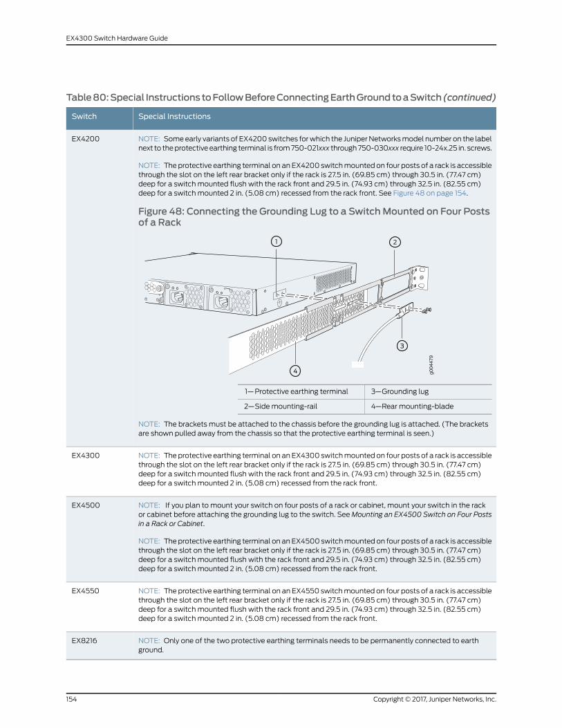
Table80:Special InstructionstoFollowBeforeConnectingEarthGroundtoaSwitch(continued)
Special InstructionsSwitch
NOTE: Someearly variants of EX4200 switches forwhich the JuniperNetworksmodel number on the labelnext to theprotective earthing terminal is from750-021xxx through750-030xxx require 10-24x.25 in. screws.
NOTE: The protective earthing terminal on an EX4200 switchmounted on four posts of a rack is accessiblethrough the slot on the left rear bracket only if the rack is 27.5 in. (69.85 cm) through 30.5 in. (77.47 cm)deep for a switch mounted flush with the rack front and 29.5 in. (74.93 cm) through 32.5 in. (82.55 cm)deep for a switch mounted 2 in. (5.08 cm) recessed from the rack front. See Figure 48 on page 154.
Figure 48: Connecting the Grounding Lug to a SwitchMounted on Four Postsof a Rack
g004
479
3—1— Grounding lugProtective earthing terminal
4—2— Rear mounting-bladeSide mounting-rail
NOTE: The brackets must be attached to the chassis before the grounding lug is attached. (The bracketsare shown pulled away from the chassis so that the protective earthing terminal is seen.)
EX4200
NOTE: The protective earthing terminal on anEX4300 switchmounted on four posts of a rack is accessiblethrough the slot on the left rear bracket only if the rack is 27.5 in. (69.85 cm) through 30.5 in. (77.47 cm)deep for a switch mounted flush with the rack front and 29.5 in. (74.93 cm) through 32.5 in. (82.55 cm)deep for a switch mounted 2 in. (5.08 cm) recessed from the rack front.
EX4300
NOTE: If you plan to mount your switch on four posts of a rack or cabinet, mount your switch in the rackor cabinet before attaching the grounding lug to the switch. SeeMounting an EX4500 Switch on Four Postsin a Rack or Cabinet.
NOTE: Theprotective earthing terminal on anEX4500 switchmountedon four posts of a rack is accessiblethrough the slot on the left rear bracket only if the rack is 27.5 in. (69.85 cm) through 30.5 in. (77.47 cm)deep for a switch mounted flush with the rack front and 29.5 in. (74.93 cm) through 32.5 in. (82.55 cm)deep for a switch mounted 2 in. (5.08 cm) recessed from the rack front.
EX4500
NOTE: The protective earthing terminal on an EX4550 switchmounted on four posts of a rack is accessiblethrough the slot on the left rear bracket only if the rack is 27.5 in. (69.85 cm) through 30.5 in. (77.47 cm)deep for a switch mounted flush with the rack front and 29.5 in. (74.93 cm) through 32.5 in. (82.55 cm)deep for a switch mounted 2 in. (5.08 cm) recessed from the rack front.
EX4550
NOTE: Only one of the two protective earthing terminals needs to be permanently connected to earthground.
EX8216
Copyright © 2017, Juniper Networks, Inc.154
EX4300 Switch Hardware Guide
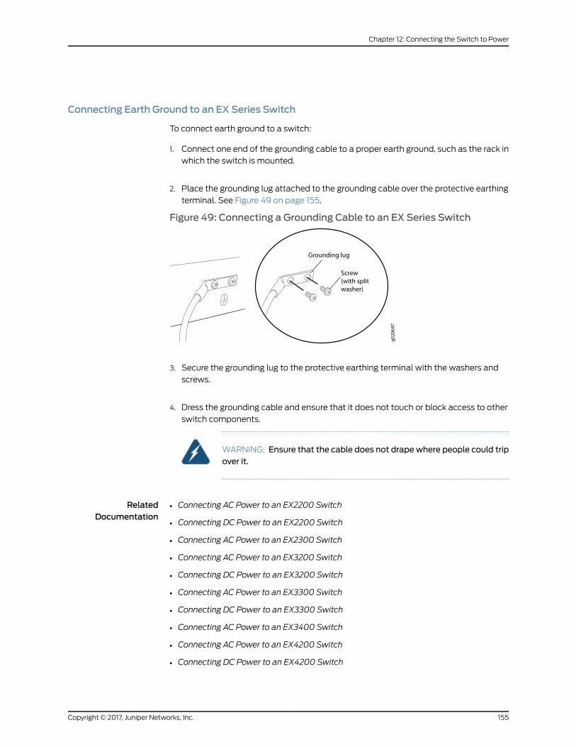
Connecting Earth Ground to an EX Series Switch
To connect earth ground to a switch:
1. Connect one end of the grounding cable to a proper earth ground, such as the rack in
which the switch is mounted.
2. Place the grounding lug attached to the grounding cable over the protective earthing
terminal. See Figure 49 on page 155.
Figure 49: Connecting a Grounding Cable to an EX Series Switch
3. Secure the grounding lug to the protective earthing terminal with the washers and
screws.
4. Dress the grounding cable and ensure that it does not touch or block access to other
switch components.
WARNING: Ensure that the cable does not drapewhere people could tripover it.
RelatedDocumentation
Connecting AC Power to an EX2200 Switch•
• Connecting DC Power to an EX2200 Switch
• Connecting AC Power to an EX2300 Switch
• Connecting AC Power to an EX3200 Switch
• Connecting DC Power to an EX3200 Switch
• Connecting AC Power to an EX3300 Switch
• Connecting DC Power to an EX3300 Switch
• Connecting AC Power to an EX3400 Switch
• Connecting AC Power to an EX4200 Switch
• Connecting DC Power to an EX4200 Switch
155Copyright © 2017, Juniper Networks, Inc.
Chapter 12: Connecting the Switch to Power

• Connecting AC Power to an EX4300 Switch on page 156
• Connecting DC Power to an EX4300 Switch on page 159
• Connecting AC Power to an EX4500 Switch
• Connecting DC Power to an EX4500 Switch
• Connecting AC Power to an EX4550 Switch
• Connecting DC Power to an EX4550 Switch
• Connecting AC Power to an EX6200 Switch
• Connecting DC Power to an EX6200 Switch
• Connecting AC Power to an EX8200 Switch
• Connecting DC Power to an EX8200 Switch
• Connecting AC Power to an EX9204 Switch
• Connecting DC Power to an EX9204 Switch
• Connecting AC Power to an EX9208 Switch
• Connecting DC Power to an EX9208 Switch
• Connecting AC Power to an EX9214 Switch
• Connecting DC Power to an EX9214 Switch
• General Safety Guidelines andWarnings on page 261
• Grounded EquipmentWarning on page 276
Connecting AC Power to an EX4300 Switch
EX4300 switches support 350W, 715W, or 1100WAC power supplies depending on the
switch model. After you install at least one power supply, you can connect power to the
switch.
CAUTION: Do notmix:
• AC and DC power supplies in the same chassis
• Power supplies with different airflow labels (AIR IN (AFI) and AIR OUT
(AFO)) in the same chassis.
• Fanmoduleswith different airflow labels (AIR IN (AFI)andAIROUT(AFO))
in the same chassis.
• Power supplies and fanmodules with different airflow labels (AIR IN (AFI)
and AIR OUT (AFO)) in the same chassis.
Before you begin connecting AC power to an EX4300 switch:
Copyright © 2017, Juniper Networks, Inc.156
EX4300 Switch Hardware Guide
• Ensure that youhave taken thenecessaryprecautions topreventelectrostaticdischarge
(ESD) damage (see “Prevention of Electrostatic Discharge Damage” on page 291).
• Ensure that you have connected the device chassis to earth ground.
CAUTION: Before you connect power to the switch, a licensed electricianmust attach a cable lug to the grounding cable that you supply. A cablewith an incorrectly attached lug can damage the switch (for example, bycausing a short circuit).
Tomeet safety and electromagnetic interference (EMI) requirements andto ensure proper operation, youmust connect the EX4300 switch to earthground before you connect it to power. For installations that require aseparate grounding conductor to the chassis, use the protective earthingterminal on the switch chassis to connect to the earth ground. Forinstructions on connecting earth ground, see “Connecting Earth Ground toan EX Series Switch” on page 149. An EX4300 switch gains additionalgrounding when you plug the power supply in the switch into a groundedAC power outlet by using the AC power cord appropriate for yourgeographical location (see “AC Power Cord Specifications for an EX4300Switch” on page 100).
• Install the power supply in the chassis. For instructions on installing a power supply in
anEX4300switch,see“InstallinganACPowerSupply inanEX4300Switch”onpage205.
Ensure that you have the following parts and tools available:
• A power cord appropriate for your geographical location (provided)
NOTE: Each power supply must be connected to a dedicated power sourceoutlet.
To connect AC power to an EX4300 switch:
1. Attach the grounding strap to your bare wrist and to a site ESD point.
NOTE: The power supply slots are at the right end of the rear panel on24-port and 48-port switches, and at the left end on 32-portswitches.Figure 50 on page 158 shows how to connect an AC power cordto an AC power supply installed on 24-port or 48-port EX4300 switches.The procedure is the same for 32-port EX4300 switches.
2. Ensure that the power supplies are fully inserted in the chassis and the latches are
secure. If only one power supply is installed, ensure that a cover panel is installed over
the second power supply slot.
157Copyright © 2017, Juniper Networks, Inc.
Chapter 12: Connecting the Switch to Power

3. Locate the power cord and power cord retainer shipped with the switch; the cords
have plugs appropriate for your geographical location. See “AC Power Cord
Specifications for an EX4300 Switch” on page 100.
4. Push the end of the retainer strip into the hole next to the inlet on the power supply
face plate until it snaps into place. Ensure that the loop in the retainer strip faces
toward the power cord.
5. Press the small tab on the retainer strip to loosen the loop. Slide the loop until you
have enough space to insert the power cord coupler into the inlet.
6. Insert the power cord coupler firmly into the inlet.
7. Slide the loop toward the power supply until it is snug against the base of the coupler.
8. Press the tab on the loop and draw out the loop into a tight circle (see
Figure 50 on page 158).
Figure 50: Connecting an AC Power Cord to an AC Power Supply in anEX4300 Switch
9. If the AC power source outlet has a power switch, set it to the OFF (O) position.
10. Insert the power cord plug into an AC power source outlet.
11. If the AC power source outlet has a power switch, set it to the ON (|) position.
12. Verify that the IN OK andOUTOK LEDs on each power supply are lit green.
If theOUTOK LED is lit amber, remove power from the power supply, and replace the
power supply (see “Removing an AC Power Supply from an EX4300 Switch” on
page207).Donot remove thepower supplyuntil youhavea replacementpower supply
Copyright © 2017, Juniper Networks, Inc.158
EX4300 Switch Hardware Guide

ready: the power supplies or a cover panel must be installed in the switch to ensure
proper airflow.
CAUTION: We recommend that you install either a replacement powersupply or a cover panel in the empty power supply slot to prevent chassisoverheating and dust accumulation.
RelatedDocumentation
AC Power Supply in EX4300 Switches on page 49•
• AC Power Supply LEDs in EX4300 Switches on page 56
Connecting DC Power to an EX4300 Switch
EX4300 switches can be configured with up to two DC power supplies. After you install
at least one power supply, you can connect power to the switch.
CAUTION: Do notmix:
• AC and DC power supplies in the same chassis
• Power supplies with different airflow labels (AIR IN (AFI) and AIR OUT
(AFO)) in the same chassis.
• Fanmoduleswith different airflow labels (AIR IN (AFI)andAIROUT(AFO))
in the same chassis.
• Power supplies and fanmodules with different airflow labels (AIR IN (AFI)
and AIR OUT (AFO)) in the same chassis.
Before you begin connecting DC power to an EX4300 switch:
• Ensure that youhave taken thenecessaryprecautions topreventelectrostaticdischarge
(ESD) damage (see “Prevention of Electrostatic Discharge Damage” on page 291).
• Ensure that you have connected the switch chassis to earth ground.
CAUTION: Ensure that you install the power supply module first and theninstall the DC input wire, before closing input breaker ON.
CAUTION: Before you connect power to the device, a licensed electricianmustattachacable lug to thegroundingandpower cables that yousupply.A cable with an incorrectly attached lug can damage the device (forexample, by causing a short circuit).
159Copyright © 2017, Juniper Networks, Inc.
Chapter 12: Connecting the Switch to Power
Tomeet safety and electromagnetic interference (EMI) requirements andto ensure proper operation, youmust connect the chassis to earth groundbefore you connect it to power. For installations that require a separategrounding conductor to the chassis, use the protective earthing terminalon the switch chassis to connect to the earth ground. For instructions onconnecting earth ground, see “Connecting Earth Ground to an EX SeriesSwitch” on page 149.
• Install the power supply in the chassis. For instructions on installing aDCpower supply
in an EX4300 switch, see “Installing a DC Power Supply in an EX4300 Switch” on
page 208.
Ensure that you have the following parts and tools available:
• DC power source cables (14–16 AWG) with ring lug (Molex 190700067 or equivalent)
(not provided)
• Phillips (+) screwdriver, number 2 (not provided)
• Multimeter (not provided)
• A 14AWG(2mm²),minimum90°Cwire grounding cable, or one permitted by the local
code,withaPanduit LCC10-14BWLorequivalentgrounding lugattached(notprovided)
• Two 10-32 x .25 in. screws with #10 split-lock washer (not provided)
• Two #10 flat washers (not provided)
To connect DC power to an EX4300 switch:
1. Attach the grounding strap to your bare wrist and to a site ESD point.
NOTE: The power supply slots are at the right end of the rear panel on24-port and 48-port switches, and at the left end on 32-port switches.Figure51onpage 163showshowtosecure ring lugs to the terminalson theDC power supply installed on 24-port or 48-port EX4300 switches. Theprocedure is the same for 32-port EX4300 switches.
2. Verify that the DC power cables are correctly labeled before making connections to
thepower supply. In a typical powerdistribution schemewhere the return is connected
to chassis groundat thebattery plant, youcanuseamultimeter to verify the resistance
of the –48V and RTN DC cables to chassis ground:
• The cable with very low resistance (indicating a closed circuit) to chassis ground is
positive (+) and will be installed on the V+ (return) DC power input terminal.
• The cable with very high resistance (indicating an open circuit) to chassis ground
is negative (–) and will be installed on the V– (input) DC power input terminal.
Copyright © 2017, Juniper Networks, Inc.160
EX4300 Switch Hardware Guide
CAUTION: Youmust ensure that power connectionsmaintain the properpolarity. Thepower source cablesmight be labeled (+)and (–) to indicatetheir polarity. There is no standard color coding for DC power cables. Thecolor coding usedby the externalDCpower source at your site determinesthe color coding for the leads on the power cables that attach to the DCpower input terminals on each power supply.
3. Ensure that the input circuit breaker is open so that the voltage across the DC power
source cable leads is 0 V and that the cable leads will not become active while you
are connecting DC power.
NOTE: The V+ terminals are referred to as +RTN and V– terminals arereferred to as–48V in “DCPowerWiringSequenceWarning” onpage 299and “DC Power Electrical Safety Guidelines for Switches” on page 294.
4. Ensure that the power supplies are fully inserted in the chassis.
5. Remove the terminal block cover. The terminal block cover is a piece of clear plastic
that snaps into place over the terminal block.
6. Remove the screws on the terminals by using the screwdriver. Save the screws.
WARNING: Ensure that the power cables do not block access to switchcomponents or drape where people can trip on them.
NOTE: The DC power supply has five terminals, two positive terminalslabeled V+ and two negative terminals labeled V–, for connecting thepower supply to a dedicated DC power source by using the DC powersource cables labeled positive (+) and negative (–), and one terminal forconnecting the power supply to earth ground (see Figure 51 on page 163).The V+ terminals are shunted internally together, as are the V– terminalsto provide parallel current path.
7. Connect one end of the grounding cable to a proper earth ground, such as the rack in
which the switch is mounted.
8. Place the grounding lug attached to the grounding cable over the earthing terminal
on the DC power supply.
161Copyright © 2017, Juniper Networks, Inc.
Chapter 12: Connecting the Switch to Power

9. Secure the grounding lug to the protective earthing terminal with the washers and
screws.
10. Dress the grounding cable and ensure that it does not touch or block access to other
switch components.
WARNING: Ensure that the cable does not drapewhere people could tripover it.
11. Connect each power supply to the power source. Secure power source cables to the
power supplies by screwing the ring lugs attached to the cables to the appropriate
terminals by using the screw from the terminals (see Figure 51 on page 163).
• To connect a power supply to a power source:
a. Secure the ring lug of the positive (+) DC power source cable to one of the
+ terminals on the DC power supply.
b. Secure the ring lug of the negative (–) DC power source cable to the – terminal
adjacent to the + terminal that you connected to on the DC power supply.
c. Connect the ground wire to earth ground if the switch is not in a grounded rack.
d. Tighten the screws on the power supply terminals until they are snug by using
the screwdriver. Donotovertighten—applybetween5 lb-in (0.56Nm)and6 lb-in
(0.68 Nm) of torque to the screws.
If you have a second installed power supply, connect it in the sameway you did the
first.
• To connect one power supply to two power sources:
a. Secure the ring lug of the positive (+) DC power source cable from the first DC
power source to a + terminal on the power supply.
b. Secure the ring lug of the negative (–) DC power source cable from the first DC
power source to the– terminal adjacent to the+ terminal on theDCpower supply
to which you connected the ring lug of the positive (+) DC power source cable
from the first DC power source.
c. Secure the ring lug of the positive (+) DC power source cable from the second
DC power source to the other + terminal on the power supply.
d. Secure the ring lug of the negative (–) DC power source cable from the second
DC power source to the – terminal adjacent to the + terminal on the DC power
Copyright © 2017, Juniper Networks, Inc.162
EX4300 Switch Hardware Guide

supply to which you connected the ring lug of the positive (+) DC power source
cable from the second DC power source.
e. Connect the ground wire to earth ground if the switch is not in a grounded rack.
f. Tighten the screws on the power supply terminals on both the power supplies
until snug using the screwdriver. Do not overtighten—apply between 8 lb-in.
(0.9 Nm) and 9 lb-in. (1.02 Nm) of torque to the screws.
If you have a second installed power supply, connect it in the sameway you did the
first.
Figure 51: Securing Ring Lugs to the Terminals on the DC Power Supply
12. Replace the terminal block cover.
13. Close the input circuit breaker.
14. Verify that the IN OK andOUTOK LEDs on the power supply are lit green and are on
steadily.
RelatedDocumentation
• DC Power Supply in EX4300 Switches on page 57
• DC Power Supply LEDs in EX4300 Switches on page 62
163Copyright © 2017, Juniper Networks, Inc.
Chapter 12: Connecting the Switch to Power

Copyright © 2017, Juniper Networks, Inc.164
EX4300 Switch Hardware Guide
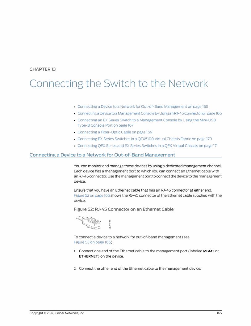
CHAPTER 13
Connecting the Switch to the Network
• Connecting a Device to a Network for Out-of-Band Management on page 165
• ConnectingaDevice toaManagementConsolebyUsinganRJ-45Connectoronpage166
• Connecting an EX Series Switch to a Management Console by Using the Mini-USB
Type-B Console Port on page 167
• Connecting a Fiber-Optic Cable on page 169
• Connecting EX Series Switches in a QFX5100 Virtual Chassis Fabric on page 170
• Connecting QFX Series and EX Series Switches in a QFX Virtual Chassis on page 171
Connecting a Device to a Network for Out-of-BandManagement
You canmonitor andmanage these devices by using a dedicatedmanagement channel.
Each device has amanagement port to which you can connect an Ethernet cable with
anRJ-45connector.Use themanagementport toconnect thedevice to themanagement
device.
Ensure that you have an Ethernet cable that has an RJ-45 connector at either end.
Figure 52 onpage 165 shows theRJ-45 connector of the Ethernet cable suppliedwith the
device.
Figure 52: RJ-45 Connector on an Ethernet Cable
To connect a device to a network for out-of-bandmanagement (see
Figure 53 on page 166):
1. Connect one end of the Ethernet cable to the management port (labeledMGMT or
ETHERNET) on the device.
2. Connect the other end of the Ethernet cable to the management device.
165Copyright © 2017, Juniper Networks, Inc.

Figure53:ConnectingaDevicetoaNetworkforOut-of-BandManagement
RelatedDocumentation
ConnectingaDevice toaManagementConsolebyUsinganRJ-45Connectoronpage166•
Connecting a Device to aManagement Console by Using an RJ-45 Connector
Youcanconfigureandmanage thesedevicesbyusingadedicatedmanagementchannel.
Eachdevice hasa consoleport towhich youcanconnect anEthernet cablewith anRJ-45
connector. Use the console port to connect the device to the console server or
management console. The console port accepts a cable that has an RJ-45 connector.
Ensure that you have an Ethernet cable that has an RJ-45 connector at either end. One
such cable and an RJ-45 to DB-9 serial port adapter are supplied with the device.
Figure 54 on page 166 shows the RJ-45 connector of the Ethernet cable.
Figure 54: RJ-45 Connector on an Ethernet Cable
NOTE: If your laptopor PCdoes not have aDB-9male connector pin and youwant to connect your laptop or PC directly to the device, use a combinationof the RJ-45 to DB-9 female adapter supplied with the device and a USB toDB-9male adapter. Youmust provide the USB to DB-9male adapter.
Copyright © 2017, Juniper Networks, Inc.166
EX4300 Switch Hardware Guide
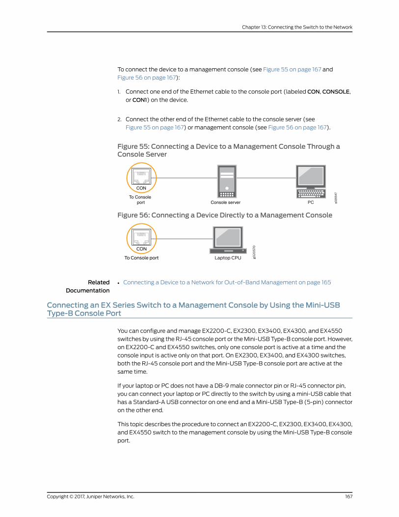
To connect the device to amanagement console (see Figure 55 on page 167 and
Figure 56 on page 167):
1. Connect one end of the Ethernet cable to the console port (labeled CON, CONSOLE,
or CON1) on the device.
2. Connect the other end of the Ethernet cable to the console server (see
Figure 55 on page 167) or management console (see Figure 56 on page 167).
Figure 55: Connecting a Device to aManagement Console Through aConsole Server
g020
547
CON
To Consoleport Console server PC
Figure 56: Connecting a Device Directly to aManagement Console
RelatedDocumentation
Connecting a Device to a Network for Out-of-Band Management on page 165•
Connecting an EX Series Switch to aManagement Console by Using theMini-USBType-B Console Port
You can configure andmanage EX2200-C, EX2300, EX3400, EX4300, and EX4550
switches by using the RJ-45 console port or theMini-USB Type-B console port. However,
on EX2200-C and EX4550 switches, only one console port is active at a time and the
console input is active only on that port. On EX2300, EX3400, and EX4300 switches,
both the RJ-45 console port and the Mini-USB Type-B console port are active at the
same time.
If your laptop or PC does not have a DB-9male connector pin or RJ-45 connector pin,
you can connect your laptop or PC directly to the switch by using amini-USB cable that
has a Standard-A USB connector on one end and a Mini-USB Type-B (5-pin) connector
on the other end.
This topic describes the procedure to connect an EX2200-C, EX2300, EX3400, EX4300,
and EX4550 switch to the management console by using the Mini-USB Type-B console
port.
167Copyright © 2017, Juniper Networks, Inc.
Chapter 13: Connecting the Switch to the Network

For information about configuring andmanaging an EX Series switch by using the RJ-45
console port, see “Connecting a Device to a Management Console by Using an RJ-45
Connector” on page 166.
Before you begin connecting the switch by using the Mini-USB Type-B console port:
• Ensure that theUSB toSerial driver is installedon thehostmachine. You candownload
thedriver fromhttps://webdownload.juniper.net/swdl/dl/secure/site/1/record/5029.html.
• Ensure that the HyperTerminal properties of the console server or laptop are set as
follows:
• Baud rate—9600
• Flow control—None
• Data—8
• Parity—None
• Stop bits—1
• DCD state—Disregard
Ensure that you have the following parts and tools available:
• Onemini-USB cable with Standard-A and Mini-USB Type-B (5-pin) connectors (not
provided).
To connect the switch to the console by using the Mini-USB Type-B console port:
1. Connect the Standard-A connector of the mini-USB cable to the host machine (PC
or laptop).
2. Connect theMini-USBType-B(5-pin)connectorof themini-USBcable to theMini-USB
Type-B console port (labeled CON) on the switch.
3. Set theMini-USBType-Bconsoleport as theactive consoleport byusing theport-type
command.
By default, the RJ-45 port is set as an active console port and the Mini-USB Type-B
port is the passive console port. For information about configuring the console port
type, see Configuring the Console Port Type (CLI Procedure).
4. Reboot the switch.
After the connection is established, the Mini-USB Type-B becomes the active console
port. The host machine connected to the Mini-USB Type-B console port displays log
messages and enables you to control switch functionality through it.
RelatedDocumentation
Connecting a Device to a Network for Out-of-Band Management on page 165•
• Console Port Connector Pinout Information on page 121
Copyright © 2017, Juniper Networks, Inc.168
EX4300 Switch Hardware Guide
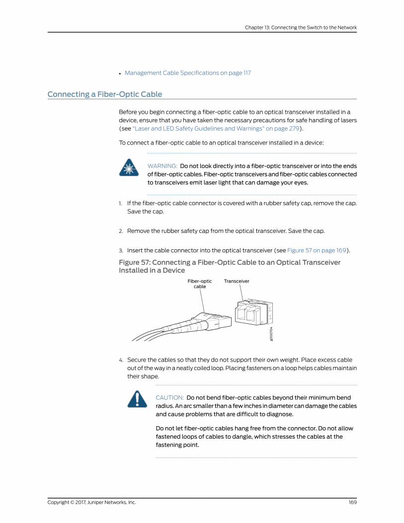
• Management Cable Specifications on page 117
Connecting a Fiber-Optic Cable
Before you begin connecting a fiber-optic cable to an optical transceiver installed in a
device, ensure that you have taken the necessary precautions for safe handling of lasers
(see “Laser and LED Safety Guidelines andWarnings” on page 279).
To connect a fiber-optic cable to an optical transceiver installed in a device:
WARNING: Do not look directly into a fiber-optic transceiver or into the endsof fiber-opticcables.Fiber-optic transceiversandfiber-opticcablesconnectedto transceivers emit laser light that can damage your eyes.
1. If the fiber-optic cable connector is coveredwith a rubber safety cap, remove the cap.
Save the cap.
2. Remove the rubber safety cap from the optical transceiver. Save the cap.
3. Insert the cable connector into the optical transceiver (see Figure 57 on page 169).
Figure 57: Connecting a Fiber-Optic Cable to an Optical TransceiverInstalled in a Device
4. Secure the cables so that they do not support their own weight. Place excess cable
outof theway inaneatly coiled loop.Placing fastenersona loophelps cablesmaintain
their shape.
CAUTION: Do not bend fiber-optic cables beyond their minimum bendradius.Anarcsmaller thana few inches indiametercandamagethecablesand cause problems that are difficult to diagnose.
Do not let fiber-optic cables hang free from the connector. Do not allowfastened loops of cables to dangle, which stresses the cables at thefastening point.
169Copyright © 2017, Juniper Networks, Inc.
Chapter 13: Connecting the Switch to the Network

RelatedDocumentation
Disconnecting a Fiber-Optic Cable from a Device on page 226•
• Installing a Transceiver on page 219
• Maintaining Fiber-Optic Cables on page 227
Connecting EX Series Switches in a QFX5100 Virtual Chassis Fabric
A Juniper Networks QFX5100 Virtual Chassis Fabric (VCF) is constructed using a
spine-and-leaf architecture and topology. In the spine-and-leaf architecture, each spine
device is interconnected to each leaf device. A VCF supports up to 20 total devices, and
up to 4 devices can be configured into spine devices. EX4300 devices are supported in
the leaf role in a QFX5100 VCF. To understand the different hardware configurations
supported, see Virtual Chassis Fabric Hardware Overview.
Althoughbestpractice is touseallQFX5100switches in theVCF, youcanalsouseEX4300
switches as leaf devices.
Installations with combinations of QFX5100-48T, QFX3600, QFX3500, and EX4300 as
leafdevices in theQFX5100VCFarecalledmixedmode.All VCF installations cansupport
20 total devices, of which 4 QFX5100 devices can be configured into spine devices.
You can install a VCF in a single rack, multiple racks, or in wire closets. You construct a
VCF by configuring and then cabling QSFP+ interfaces into Virtual Chassis ports (VCPs).
On EX4300 switches, QSFP+ ports 0 and 1 are configured as VCP by default.
Non-channelized QSFP+ interfaces on EX4300 switches can be configured into VCPs.
The SFP+ network ports may not be configured into VCPs.
BEST PRACTICE: Use 40-Gigabit QSFP+ ports as VCPs when available.
Figure 58 on page 171 shows two QFX5100-24Q spine devices connected to a
QFX5100-48S, QFX3600, QFX3500, EX4300, and QFX5100-96S leaf devices using all
QSFP+ ports as VCPs.
Copyright © 2017, Juniper Networks, Inc.170
EX4300 Switch Hardware Guide
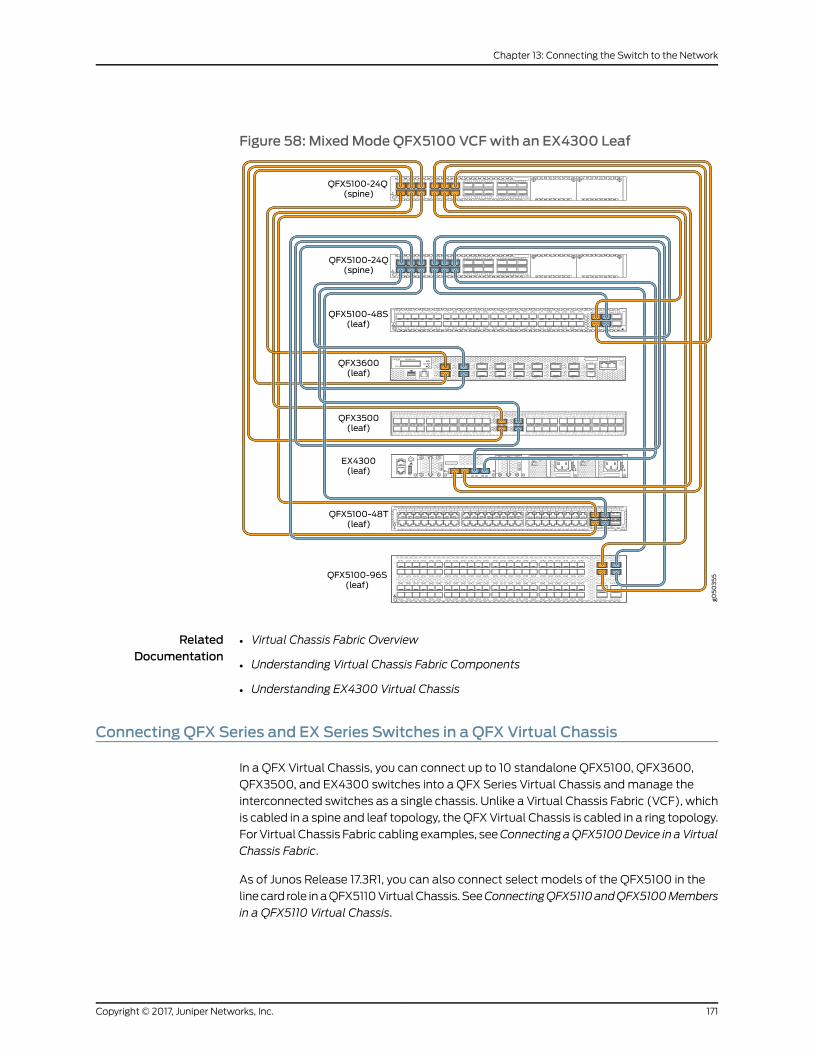
Figure 58: MixedMode QFX5100 VCFwith an EX4300 Leaf
RelatedDocumentation
Virtual Chassis Fabric Overview•
• Understanding Virtual Chassis Fabric Components
• Understanding EX4300 Virtual Chassis
Connecting QFX Series and EX Series Switches in a QFX Virtual Chassis
In a QFX Virtual Chassis, you can connect up to 10 standalone QFX5100, QFX3600,
QFX3500, and EX4300 switches into a QFX Series Virtual Chassis andmanage the
interconnected switches as a single chassis. Unlike a Virtual Chassis Fabric (VCF), which
is cabled in a spine and leaf topology, theQFXVirtual Chassis is cabled in a ring topology.
For Virtual Chassis Fabric cabling examples, seeConnecting aQFX5100Device in aVirtual
Chassis Fabric.
As of Junos Release 17.3R1, you can also connect select models of the QFX5100 in the
linecard role inaQFX5110VirtualChassis. SeeConnectingQFX5110andQFX5100Members
in a QFX5110 Virtual Chassis.
171Copyright © 2017, Juniper Networks, Inc.
Chapter 13: Connecting the Switch to the Network

This topic describes how to cable QFX Series switches and EX4300 switches into a QFX
Virtual Chassis.
• Before You Start on page 172
• Valid Configurations on page 173
• Cabling QFX3500 Switches in a QFX5100 Virtual Chassis on page 173
• Cabling QFX3600 Switches in a QFX Virtual Chassis on page 175
• Cabling a Mixed QFX Virtual Chassis on page 176
Before You Start
YouconfigureaQFXSeriesVirtualChassis by configuring the switch interfaces intoVirtual
Chassis ports (VCPs). VCPs connect switches together to form a Virtual Chassis, and
are responsible for passing all data and control traffic betweenmember switches in the
Virtual Chassis. All non-channelized QSFP+ uplink interfaces on standalone QFX5100
switchescanbeconfigured intoVCPs.All fixedSFP+ interfacesonQFX5100-96Sswitches
can also be configured into VCPs.
Use the following interfaces to create VCPs:
• On QFX5100, non-channelized QSFP+ uplink interfaces. All fixed SFP+ interfaces on
the QFX5100-96S switches are also available.
• On EX4300, non-channelized QSFP+ interfaces; Ports 0 and 1 are configured as VCP
by default. All fixed SFP+ interfaces can also be configured.
• On QFX3500 and QFX3600, all non-channelized QSFP+ and fixed SFP+ interfaces.
BEST PRACTICE: Use the 40-Gigabit QSFP+ interfaces for the VCPs.
The advantages of connecting multiple switches into a Virtual Chassis include
better-managedbandwidthatanetwork layer, simplifiedconfigurationandmaintenance
becausemultiple devices can bemanaged as a single device, increased fault tolerance
andhighavailability (HA)becauseaVirtualChassis can remainactiveandnetwork traffic
can be redirected to other member switches when a single member switch fails, and a
flatter, simplified Layer 2 network topology that minimizes or eliminates the need for
loop prevention protocols such as Spanning Tree Protocol (STP).
You can increase VCP bandwidth betweenmember switches by configuring multiple
interfaces between the same two switches into VCPs. Whenmultiple VCPs are
interconnecting the same twomember switches, a LinkAggregationGroup (LAG)bundle
is automatically formed when the VCPs are on interfaces supporting identical speeds.
For instance, if you have two 40-Gigabit QSFP+ interfaces configured as VCPs between
member switches, a LAGwith twomember links with 80 Gbps of total bandwidth is
formed. 10-Gigabit SFP+ and 40-Gigabit QSFP+ interfaces configured as VCPs cannot
bemembers of the same LAG, however. The Virtual Chassis feature is not applicable to
QFX devices in a QFabric.
Virtual Chassis can be installed in a single rack, multiple racks, or in wire closets.
Copyright © 2017, Juniper Networks, Inc.172
EX4300 Switch Hardware Guide

Valid Configurations
Valid configurations are:
• All QFX5100members–in a ring topology this is Virtual Chassis; in a spine and leaf
topology this is a Virtual Chassis Fabric (VCF). For a cabling example of spine and leaf,
see Connecting a QFX5100 Device in a Virtual Chassis Fabric.
• All QFX3600members
• All QFX3500members
• Amixture of QFX3600 and QFX3500members
• AmixtureofQFX5100,QFX3600,andQFX3500members–use theQFX5100switches
as master and backup whenever possible.
• AmixtureofQFX5100,QFX3600,QFX3500, andEX4300members. EX4300switches
as the master or backup is not supported; use QFX5100 switches in these roles
whenever possible.
An all EX4300member is simply considered an EX4300 Virtual Chassis. See
Understanding EX4300 Virtual Chassis.
If the QSFP+ interfaces are not available for VCP, 10-Gigbit interfaces can be used.
All members of the Virtual Chassis are required to run the same Junos OS Release. You
can check the version and release by issuing the show chassis version CLI command.
Cabling QFX3500 Switches in a QFX5100 Virtual Chassis
Figure 59 on page 174 is the preferred cabling method using the 40-Gigabit QSFP ports.
See Figure 60 on page 175 for an alternative method using the 10-Gigabit SFP+ ports.
173Copyright © 2017, Juniper Networks, Inc.
Chapter 13: Connecting the Switch to the Network
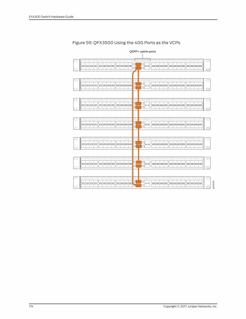
Figure 59: QFX3500Using the 40G Ports as the VCPs
LA
ST
LA
ST
LA
ST
LA
ST
Q0 Q1 Q2 Q3 24 25 26 27 28 29 30 31 32 33 34 35 36 37 38 39 40 41 42 43 44 45 46 470 1 2 3 4 5 6 7 8 9
LA
ST
LA
ST
LA
ST
LA
ST
Q0 Q1 Q2 Q3 24 25 26 27 28 29 30 31 32 33 34 35 36 37 38 39 40 41 42 43 44 45 46 470 1 2 3 4 5 6 7 8 9
LA
ST
LA
ST
LA
ST
LA
ST
Q0 Q1 Q2 Q3 24 25 26 27 28 29 30 31 32 33 34 35 36 37 38 39 40 41 42 43 44 45 46 470 1 2 3 4 5 6 7 8 9
LA
ST
LA
ST
LA
ST
LA
ST
Q0 Q1 Q2 Q3 24 25 26 27 28 29 30 31 32 33 34 35 36 37 38 39 40 41 42 43 44 45 46 470 1 2 3 4 5 6 7 8 9
Q0 Q1
LA
ST
LA
ST
LA
ST
LA
ST
Q2 Q3 24 25 26 27 28 29 30 31 32 33 34 35 36 37 38 39 40 41 42 43 44 45 46 470 1 2 3 4 5 6 7 8 9
LA
ST
LA
ST
LA
ST
LA
ST
Q0 Q1 Q2 Q3 24 25 26 27 28 29 30 31 32 33 34 35 36 37 38 39 40 41 42 43 44 45 46 470 1 2 3 4 5 6 7 8 9
LA
ST
LA
ST
LA
ST
LA
ST
Q0 Q1 Q2 Q3 24 25 26 27 28 29 30 31 32 33 34 35 36 37 38 39 40 41 42 43 44 45 46 470 1 2 3 4 5 6 7 8 9
10 11 12 13 14 15 16 17 18 19 20 21 22 23
10 11 12 13 14 15 16 17 18 19 20 21 22 23
10 11 12 13 14 15 16 17 18 19 20 21 22 23
10 11 12 13 14 15 16 17 18 19 20 21 22 23
10 11 12 13 14 15 16 17 18 19 20 21 22 23
10 11 12 13 14 15 16 17 18 19 20 21 22 23
10 11 12 13 14 15 16 17 18 19 20 21 22 23
Copyright © 2017, Juniper Networks, Inc.174
EX4300 Switch Hardware Guide
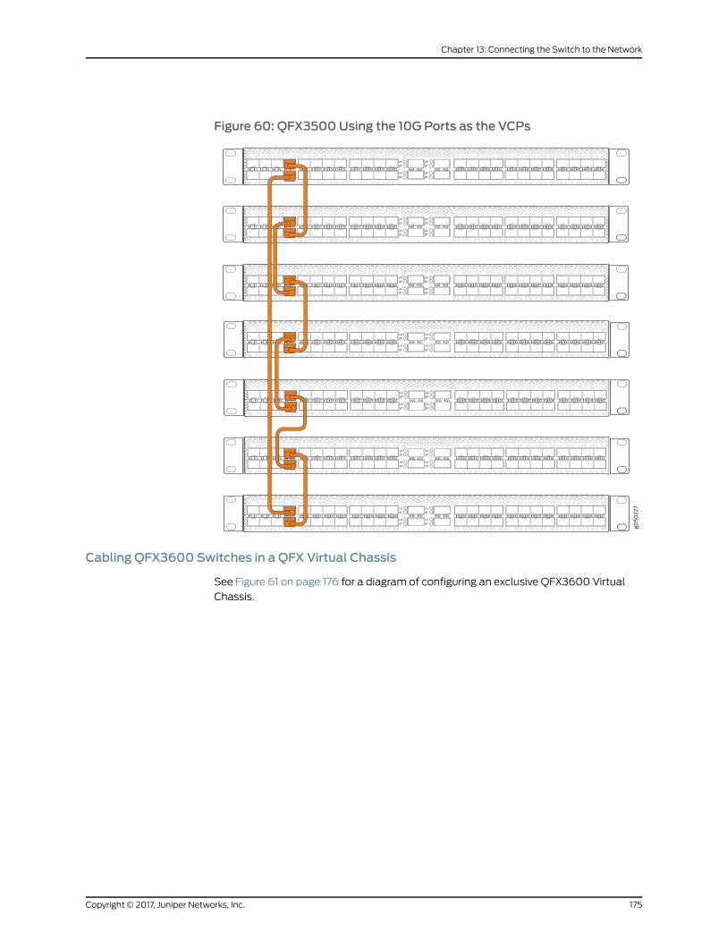
Figure 60: QFX3500Using the 10G Ports as the VCPs
LA
ST
LA
ST
LA
ST
LA
ST
Q0 Q1 Q2 Q3 24 25 26 27 28 29 30 31 32 33 34 35 36 37 38 39 40 41 42 43 44 45 46 470 1 2 3 4 5 6 7 8 9
LA
ST
LA
ST
LA
ST
LA
ST
Q0 Q1 Q2 Q3 24 25 26 27 28 29 30 31 32 33 34 35 36 37 38 39 40 41 42 43 44 45 46 470 1 2 3 4 5 6 7 8 9 10 11 12 13 14 15 16 17 18 19 20 21 22 23
LA
ST
LA
ST
LA
ST
LA
ST
Q0 Q1 Q2 Q3 24 25 26 27 28 29 30 31 32 33 34 35 36 37 38 39 40 41 42 43 44 45 46 470 1 2 3 4 5 6 7 8 9
LA
ST
LA
ST
LA
ST
LA
ST
Q0 Q1 Q2 Q3 24 25 26 27 28 29 30 31 32 33 34 35 36 37 38 39 40 41 42 43 44 45 46 470 1 2 3 4 5 6 7 8 9
LA
ST
LA
ST
LA
ST
LA
ST
Q0 Q1 Q2 Q3 24 25 26 27 28 29 30 31 32 33 34 35 36 37 38 39 40 41 42 43 44 45 46 470 1 2 3 4 5 6 7 8 9
LA
ST
LA
ST
LA
ST
LA
ST
Q0 Q1 Q2 Q3 24 25 26 27 28 29 30 31 32 33 34 35 36 37 38 39 40 41 42 43 44 45 46 470 1 2 3 4 5 6 7 8 9 10 11 12 13 14 15 16 17 18 19 20 21 22 23
10 11 12 13 14 15 16 17 18 19 20 21 22 23
10 11 12 13 14 15 16 17 18 19 20 21 22 23
10 11 12 13 14 15 16 17 18 19 20 21 22 23
10 11 12 13 14 15 16 17 18 19 20 21 22 23
LA
ST
LA
ST
LA
ST
LA
ST
Q0 Q1 Q2 Q3 24 25 26 27 28 29 30 31 32 33 34 35 36 37 38 39 40 41 42 43 44 45 46 470 1 2 3 4 5 6 7 8 9 10 11 12 13 14 15 16 17 18 19 20 21 22 23
Cabling QFX3600 Switches in a QFX Virtual Chassis
See Figure 61 on page 176 for a diagram of configuring an exclusive QFX3600 Virtual
Chassis.
175Copyright © 2017, Juniper Networks, Inc.
Chapter 13: Connecting the Switch to the Network
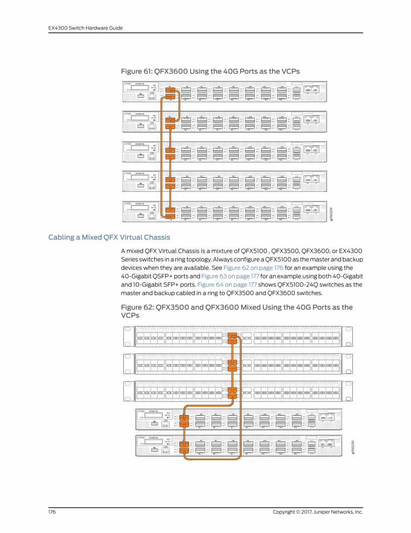
Figure 61: QFX3600Using the 40G Ports as the VCPs
OK /!
QFX3600-16Q
CON
LA
ST
LA
ST
Q0
Q1
LA
ST
LA
ST
Q2
Q3
LA
ST
LA
ST
Q4
Q5
LA
ST
LA
ST
Q6
Q7
LA
ST
LA
ST
Q8
Q9
LA
ST
LA
ST
Q10
Q11
LA
ST
LA
ST
Q12
Q13
LA
ST
LA
ST
Q14
Q15
LA
ST
LA
STC1 S
C0 C1
C0 S
OK /!
QFX3600-16Q
CON
LA
ST
LA
ST
Q0
Q1
LA
ST
LA
ST
Q2
Q3
LA
ST
LA
ST
Q4
Q5
LA
ST
LA
ST
Q6
Q7
LA
ST
LA
ST
Q8
Q9
LA
ST
LA
ST
Q10
Q11
LA
ST
LA
ST
Q12
Q13
LA
ST
LA
ST
Q14
Q15
LA
ST
LA
STC1 S
C0 C1
C0 S
OK /!
QFX3600-16Q
CON
LA
ST
LA
ST
Q0
Q1
LA
ST
LA
ST
Q2
Q3
LA
ST
LA
ST
Q4
Q5
LA
ST
LA
ST
Q6
Q7
LA
ST
LA
ST
Q8
Q9
LA
ST
LA
ST
Q10
Q11
LA
ST
LA
ST
Q12
Q13
LA
ST
LA
ST
Q14
Q15
LA
ST
LA
STC1 S
C0 C1
C0 S
OK /!
QFX3600-16Q
CON
LA
ST
LA
ST
Q0
Q1
LA
ST
LA
ST
Q2
Q3
LA
ST
LA
ST
Q4
Q5
LA
ST
LA
ST
Q6
Q7
LA
ST
LA
ST
Q8
Q9
LA
ST
LA
ST
Q10
Q11
LA
ST
LA
ST
Q12
Q13
LA
ST
LA
ST
Q14
Q15
LA
ST
LA
STC1 S
C0 C1
C0 S
OK /!
QFX3600-16Q
CON
LA
ST
LA
ST
Q0
Q1
LA
ST
LA
ST
Q2
Q3
LA
ST
LA
ST
Q4
Q5
LA
ST
LA
ST
Q6
Q7
LA
ST
LA
ST
Q8
Q9
LA
ST
LA
ST
Q10
Q11
LA
ST
LA
ST
Q12
Q13
LA
ST
LA
ST
Q14
Q15
LA
ST
LA
STC1 S
C0 C1
C0 S
Cabling aMixed QFX Virtual Chassis
Amixed QFX Virtual Chassis is a mixture of QFX5100 , QFX3500, QFX3600, or EX4300
Series switches in a ring topology. Always configureaQFX5100as themaster andbackup
devices when they are available. See Figure 62 on page 176 for an example using the
40-GigabitQSFP+ports and Figure 63onpage 177 for an example using both 40-Gigabit
and 10-Gigabit SFP+ ports. Figure 64 on page 177 shows QFX5100-24Q switches as the
master and backup cabled in a ring to QFX3500 and QFX3600 switches.
Figure 62: QFX3500 andQFX3600Mixed Using the 40G Ports as theVCPs
LA
ST
LA
ST
LA
ST
LA
ST
Q0 Q1 Q2 Q3 24 25 26 27 28 29 30 31 32 33 34 35 36 37 38 39 40 41 42 43 44 45 46 470 1 2 3 4 5 6 7 8 9
OK /!
QFX3600-16Q
CON
LA
ST
LA
ST
Q0
Q1
LA
ST
LA
ST
Q2
Q3
LA
ST
LA
ST
Q4
Q5
LA
ST
LA
ST
Q6
Q7
LA
ST
LA
ST
Q8
Q9
LA
ST
LA
ST
Q10
Q11
LA
ST
LA
ST
Q12
Q13
LA
ST
LA
ST
Q14
Q15
LA
ST
LA
STC1 S
C0 C1
C0 S
OK /!
QFX3600-16Q
CON
LA
ST
LA
ST
Q0
Q1
LA
ST
LA
ST
Q2
Q3
LA
ST
LA
ST
Q4
Q5
LA
ST
LA
ST
Q6
Q7
LA
ST
LA
ST
Q8
Q9
LA
ST
LA
ST
Q10
Q11
LA
ST
LA
ST
Q12
Q13
LA
ST
LA
ST
Q14
Q15
LA
ST
LA
STC1 S
C0 C1
C0 S
LA
ST
LA
ST
LA
ST
LA
ST
Q0 Q1 Q2 Q3 24 25 26 27 28 29 30 31 32 33 34 35 36 37 38 39 40 41 42 43 44 45 46 470 1 2 3 4 5 6 7 8 9
LA
ST
LA
ST
LA
ST
LA
ST
Q0 Q1 Q2 Q3 24 25 26 27 28 29 30 31 32 33 34 35 36 37 38 39 40 41 42 43 44 45 46 470 1 2 3 4 5 6 7 8 9 10 11 12 13 14 15 16 17 18 19 20 21 22 23
10 11 12 13 14 15 16 17 18 19 20 21 22 23
10 11 12 13 14 15 16 17 18 19 20 21 22 23
Copyright © 2017, Juniper Networks, Inc.176
EX4300 Switch Hardware Guide

Figure 63: QFX3500andQFX3600MixedUsing Both 40GPorts and 10GPorts as the VCPs
LA
ST
LA
ST
LA
ST
LA
ST
Q0 Q1 Q2 Q3 24 25 26 27 28 29 30 31 32 33 34 35 36 37 38 39 40 41 42 43 44 45 46 470 1 2 3 4 5 6 7 8 9
LA
ST
LA
ST
LA
ST
LA
ST
Q0 Q1 Q2 Q3 24 25 26 27 28 29 30 31 32 33 34 35 36 37 38 39 40 41 42 43 44 45 46 470 1 2 3 4 5 6 7 8 9
OK /!
QFX3600-16Q
CON
LA
ST
LA
ST
Q0
Q1
LA
ST
LA
ST
Q2
Q3
LA
ST
LA
ST
Q4
Q5
LA
ST
LA
ST
Q6
Q7
LA
ST
LA
ST
Q8
Q9
LA
ST
LA
ST
Q10
Q11
LA
ST
LA
ST
Q12
Q13
LA
ST
LA
ST
Q14
Q15
LA
ST
LA
STC1 S
C0 C1
C0 S
OK /!
QFX3600-16Q
CON
LA
ST
LA
ST
Q0
Q1
LA
ST
LA
ST
Q2
Q3
LA
ST
LA
ST
Q4
Q5
LA
ST
LA
ST
Q6
Q7
LA
ST
LA
ST
Q8
Q9
LA
ST
LA
ST
Q10
Q11
LA
ST
LA
ST
Q12
Q13
LA
ST
LA
ST
Q14
Q15
LA
ST
LA
STC1 S
C0 C1
C0 S
10 11 12 13 14 15 16 17 18 19 20 21 22 23
10 11 12 13 14 15 16 17 18 19 20 21 22 23
Figure 64: QFX5100Master Connecting QFX3600 andQFX3500Using40G Ports as VCPs
LA
ST
LA
ST
LA
ST
LA
ST
Q0 Q1 Q2 Q3 24 25 26 27 28 29 30 31 32 33 34 35 36 37 38 39 40 41 42 43 44 45 46 470 1 2 3 4 5 6 7 8 9 34 35 36 37 38 39 40 41 42 43 44 45 46 47
ST
LA
ST
LA
ST
LA
ST
LA
ST
Q0 Q1 Q2 Q3 24 25 26 27 28 29 30 31 32 33 34 35 36 37 38 39 40 41 42 43 44 45 46 470 1 2 3 4 5 6 7 8 9 34 35 36 37 38 39 40 41 42 43 44 45 46 47
ST
2018 22
19 21 23
1412 16
13 15 17
86 10
7 9 11
20 4
3 51
2018 22
19 21 23
1412 16
13 15 17
86 10
7 9 11
20 4
3 51
g050
334
RelatedDocumentation
• Understanding QFX Series Virtual Chassis
• Connecting QFX5110 and QFX5100 Members in a QFX5110 Virtual Chassis
177Copyright © 2017, Juniper Networks, Inc.
Chapter 13: Connecting the Switch to the Network

• Adding a New Switch to an Existing QFX Series Virtual Chassis (CLI Procedure)
• Connecting QFX Series and EX Series Switches in a QFX Virtual Chassis
• Connecting a QFX5100 Device in a Virtual Chassis Fabric
Copyright © 2017, Juniper Networks, Inc.178
EX4300 Switch Hardware Guide
CHAPTER 14
Performing Initial Configuration
• EX4300 Default Configuration on page 179
• Connecting and Configuring an EX Series Switch (CLI Procedure) on page 187
• Connecting and Configuring an EX Series Switch (J-Web Procedure) on page 190
• Configuring the LCD Panel on EX Series Switches (CLI Procedure) on page 195
EX4300 Default Configuration
Each EX Series switch is programmedwith a factory default configuration that contains
the values set for each configuration parameter when the switch is shipped. The default
configuration file sets values for systemparameters suchas syslogandcommit, configures
Ethernet switching on all interfaces, enables IGMP snooping, and enables the LLDP and
RSTP protocols.
The following default configuration file is for an EX4300-24T switch:
NOTE:
• The factory default configuration file hasmore interfaces for models thathavemore ports.
• The poe statement does not appear for models without PoE+ ports.
Interfaces ge-0/0/0 through ge-0/0/23 are network port interfaces.Interfaces ge-0/2/0 through ge-0/2/3 and xe-0/2/0 through xe-0/2/3 areSFP/SFP+ uplink module port interfaces.
Whenyoucommit changes to the configuration, a newconfiguration file is created,which
becomes the active configuration. You can always revert to the factory default
configuration. See Reverting to the Default Factory Configuration for the EX Series Switch.
system {auto-snapshot;syslog {user * {any emergency;
}file messages {any notice;
179Copyright © 2017, Juniper Networks, Inc.

authorization info;}file interactive-commands {interactive-commands any;
}}commit {factory-settings {reset-virtual-chassis-configuration;reset-chassis-lcd-menu;
}}
}interfaces {ge-0/0/0 {unit 0 {family ethernet-switching;vlan {members default;
}storm-control default;
}}
}ge-0/0/1 {unit 0 {family ethernet-switching;vlan {members default;
}storm-control default;
}}
}ge-0/0/2 {unit 0 {family ethernet-switching;vlan {members default;
}storm-control default;
}}
}ge-0/0/3 {unit 0 {family ethernet-switching;vlan {members default;
}storm-control default;
}}
}ge-0/0/4 {unit 0 {
Copyright © 2017, Juniper Networks, Inc.180
EX4300 Switch Hardware Guide

family ethernet-switching;vlan {members default;
}storm-control default;
}}
}ge-0/0/5 {unit 0 {family ethernet-switching;vlan {members default;
}storm-control default;
}}
}ge-0/0/6 {unit 0 {family ethernet-switching;vlan {members default;
}storm-control default;
}}
}ge-0/0/7 {unit 0 {family ethernet-switching;vlan {members default;
}storm-control default;
}}
}ge-0/0/8 {unit 0 {family ethernet-switching;vlan {members default;
}storm-control default;
}}
}ge-0/0/9 {unit 0 {family ethernet-switching;vlan {members default;
}storm-control default;
}
181Copyright © 2017, Juniper Networks, Inc.
Chapter 14: Performing Initial Configuration
}}ge-0/0/10 {unit 0 {family ethernet-switching;vlan {members default;
}storm-control default;
}}
}ge-0/0/11 {unit 0 {family ethernet-switching;vlan {members default;
}storm-control default;
}}
}ge-0/0/12 {unit 0 {family ethernet-switching;vlan {members default;
}storm-control default;
}}
}ge-0/0/13 {unit 0 {family ethernet-switching;vlan {members default;
}storm-control default;
}}
}ge-0/0/14 {unit 0 {family ethernet-switching;vlan {members default;
}storm-control default;
}}
}ge-0/0/15 {unit 0 {family ethernet-switching;vlan {
Copyright © 2017, Juniper Networks, Inc.182
EX4300 Switch Hardware Guide
members default;}storm-control default;
}}
}ge-0/0/16 {unit 0 {family ethernet-switching;vlan {members default;
}storm-control default;
}}
}ge-0/0/17 {unit 0 {family ethernet-switching;vlan {members default;
}storm-control default;
}}
}ge-0/0/18 {unit 0 {family ethernet-switching;vlan {members default;
}storm-control default;
}}
}ge-0/0/19 {unit 0 {family ethernet-switching;vlan {members default;
}storm-control default;
}}
}ge-0/0/20 {unit 0 {family ethernet-switching;vlan {members default;
}storm-control default;
}}
}
183Copyright © 2017, Juniper Networks, Inc.
Chapter 14: Performing Initial Configuration
ge-0/0/21 {unit 0 {family ethernet-switching;vlan {members default;
}storm-control default;
}}
}ge-0/0/22 {unit 0 {family ethernet-switching;vlan {members default;
}storm-control default;
}}
}ge-0/0/23 {unit 0 {family ethernet-switching;vlan {members default;
}storm-control default;
}}
}ge-0/2/0 {unit 0 {family ethernet-switching;vlan {members default;
}storm-control default;
}}
}xe-0/2/0 {unit 0 {family ethernet-switching;vlan {members default;
}storm-control default;
}}
}ge-0/2/1 {unit 0 {family ethernet-switching;vlan {members default;
}
Copyright © 2017, Juniper Networks, Inc.184
EX4300 Switch Hardware Guide
storm-control default;}
}}xe-0/2/1 {unit 0 {family ethernet-switching;vlan {members default;
}storm-control default;
}}
}ge-0/2/2 {unit 0 {family ethernet-switching;vlan {members default;
}storm-control default;
}}
}xe-0/2/2 {unit 0 {family ethernet-switching;vlan {members default;
}storm-control default;
}}
}ge-0/2/3 {unit 0 {family ethernet-switching;vlan {members default;
}storm-control default;
}}
}xe-0/2/3 {unit 0 {family ethernet-switching;vlan {members default;
}storm-control default;
}}
}}forwarding-options {
185Copyright © 2017, Juniper Networks, Inc.
Chapter 14: Performing Initial Configuration

storm-control-profiles default {all;
}}protocols {lldp {interface all;
}lldp-med {interface all;
}igmp-snooping {vlan default;
}rstp;interface ge-0/0/0;interface ge-0/0/1;interface ge-0/0/2;interface ge-0/0/3;interface ge-0/0/4;interface ge-0/0/5;interface ge-0/0/6;interface ge-0/0/7;interface ge-0/0/8;interface ge-0/0/9;interface ge-0/0/10;interface ge-0/0/11;interface ge-0/0/12;interface ge-0/0/13;interface ge-0/0/14;interface ge-0/0/15;interface ge-0/0/16;interface ge-0/0/17;interface ge-0/0/18;interface ge-0/0/19;interface ge-0/0/20;interface ge-0/0/21;interface ge-0/0/22;interface ge-0/0/23;interface ge-0/0/24;interface ge-0/0/25;interface ge-0/0/26;interface ge-0/0/27;interface ge-0/0/28;interface ge-0/0/29;interface ge-0/0/30;interface ge-0/0/31;interface ge-0/0/32;interface ge-0/0/33;interface ge-0/0/34;interface ge-0/0/35;interface ge-0/0/36;interface ge-0/0/37;interface ge-0/0/38;interface ge-0/0/39;interface ge-0/0/40;
Copyright © 2017, Juniper Networks, Inc.186
EX4300 Switch Hardware Guide
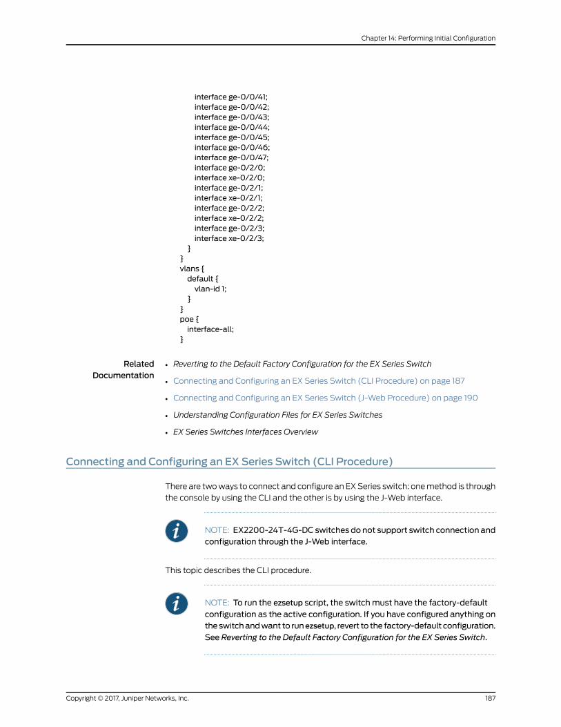
interface ge-0/0/41;interface ge-0/0/42;interface ge-0/0/43;interface ge-0/0/44;interface ge-0/0/45;interface ge-0/0/46;interface ge-0/0/47;interface ge-0/2/0;interface xe-0/2/0;interface ge-0/2/1;interface xe-0/2/1;interface ge-0/2/2;interface xe-0/2/2;interface ge-0/2/3;interface xe-0/2/3;
}}vlans {default {vlan-id 1;
}}poe {interface-all;
}
RelatedDocumentation
Reverting to the Default Factory Configuration for the EX Series Switch•
• Connecting and Configuring an EX Series Switch (CLI Procedure) on page 187
• Connecting and Configuring an EX Series Switch (J-Web Procedure) on page 190
• Understanding Configuration Files for EX Series Switches
• EX Series Switches Interfaces Overview
Connecting and Configuring an EX Series Switch (CLI Procedure)
There are twoways to connect and configure an EXSeries switch: onemethod is through
the console by using the CLI and the other is by using the J-Web interface.
NOTE: EX2200-24T-4G-DC switches do not support switch connection andconfiguration through the J-Web interface.
This topic describes the CLI procedure.
NOTE: To run the ezsetup script, the switchmust have the factory-default
configuration as the active configuration. If you have configured anything ontheswitchandwant to runezsetup, revert to the factory-default configuration.
See Reverting to the Default Factory Configuration for the EX Series Switch.
187Copyright © 2017, Juniper Networks, Inc.
Chapter 14: Performing Initial Configuration

Using the CLI, set the following parameter values in the console server or PC:
• Baud rate—9600
• Flow control—None
• Data—8
• Parity—None
• Stop bits—1
• DCD state—Disregard
To connect and configure the switch from the console by using the CLI:
1. Connect the console port to a laptop or PC by using the RJ-45 to DB-9 serial port
adapter. An Ethernet cable that has an RJ-45 connector at either end and an RJ-45
to DB-9 serial port adapter are supplied with the switch.
For the location of the console port on different EX Series switches:
• See EX2200 Switches Hardware Overview.
• See EX2300 Switches Hardware Overview.
• See Rear Panel of an EX3200 Switch.
• See Rear Panel of an EX3300 Switch.
• See Rear Panel of an EX3400 Switch.
• See Rear Panel of an EX4200 Switch.
• See “EX4300 Switches Hardware Overview” on page 3
• See Front Panel of an EX4500 Switch.
• See EX4550 Switches Hardware Overview
• See Switch Fabric and Routing Engine (SRE) Module in an EX6200 Switch.
• See Switch Fabric and Routing Engine (SRE) Module in an EX8208 Switch.
• See Routing Engine (RE) Module in an EX8216 Switch.
NOTE: In EX2200-C, EX2300, EX3400, EX4300, and EX4550 switches,you can also use theMini-USBType-B console port to connect to a laptopor PC. See “Connecting an EXSeries Switch to aManagement Console byUsing the Mini-USB Type-B Console Port” on page 167.
2. At the Junos OS shell prompt root%, type ezsetup.
3. Enter the hostname. This is optional.
Copyright © 2017, Juniper Networks, Inc.188
EX4300 Switch Hardware Guide

4. Enter the root password you want to use for the device. Reenter the root password
when prompted.
5. Enable services such as SSH and Telnet.
NOTE: Youwill not be able to log in to the switch as the root user through
Telnet. Root login is allowed only through SSH.
• The default option for SSH is yes. Select this to enable SSH.
• The default option for Telnet is no. Change this to yes to enable Telnet.
6. Use the Management Options page to select the management scenario:
NOTE: OnEX4500,EX6200,andEX8200switches,only theout-of-bandmanagement option is available.
• Configure in-bandmanagement. In in-bandmanagement, you configure a network
interface or an uplink module (expansion module) interface as the management
interface and connect it to the management device.
In this scenario, you have the following two options:
• Use the automatically createdVLAN default formanagement—Select this option
to configure all data interfaces as members of the default VLAN. Specify the
management IP address and the default gateway.
• CreateanewVLANformanagement—Select this option tocreateamanagement
VLAN. Specify the VLAN name, VLAN ID, management IP address, and default
gateway. Select the ports that must be part of this VLAN.
• Configure out-of-bandmanagement—Configure the management port. In
out-of-bandmanagement, youuseadedicatedmanagementchannel (MGMTport)
to connect to the management device. Specify the IP address and gateway of the
management interface. Use this IP address to connect to the switch.
7. Specify the SNMP read community, location, and contact to configure SNMP
parameters. These parameters are optional.
8. Specify the system date and time. Select the time zone from the list. These options
are optional.
9. The configured parameters are displayed. Enter yes to commit the configuration. Theconfiguration is committed as the active configuration for the switch.
10. (For EX4500 switches only) Enter the operational mode command request chassispic-mode intraconnect to set the PICmode to intraconnect.
189Copyright © 2017, Juniper Networks, Inc.
Chapter 14: Performing Initial Configuration
You can now log inwith the CLI or the J-Web interface to continue configuring the switch.
If you use the J-Web interface to continue configuring the switch, theWeb session is
redirected to the newmanagement IP address. If the connection cannot bemade, the
J-Web interface displays instructions for starting a J-Web session.
RelatedDocumentation
Connecting and Configuring an EX Series Switch (J-Web Procedure) on page 190•
• Installing and Connecting an EX2200 Switch
• Installing and Connecting an EX2300 Switch
• Installing and Connecting an EX3200 Switch
• Installing and Connecting an EX3300 Switch
• Installing and Connecting an EX3400 Switch
• Installing and Connecting an EX4200 Switch
• Installing and Connecting an EX4300 Switch on page 137
• Installing and Connecting an EX4550 Switch
• Installing and Connecting an EX4500 Switch
• Installing and Connecting an EX6210 Switch
• Installing and Connecting an EX8208 Switch
• Installing and Connecting an EX8216 Switch
Connecting and Configuring an EX Series Switch (J-Web Procedure)
There are twoways to connect and configure an EXSeries switch: onemethod is through
the console by using the CLI and the other is by using the J-Web interface.
NOTE: You cannot connect to and perform initial configuration ofEX2200-24T-4G-DC and EX4600 switches using EZSetup procedure fromtheJ-Web interface.ForEX2200-24T-4G-DCswitches, youmustuseEZSetupfrom the switch console, and for EX4600 switches, youmust use the CLIprocedure through the switch console.
This topic describes the J-Web procedure.
NOTE: Before you begin the configuration, enable a DHCP client on themanagementPCthatyouwill connect to theswitchso that thePCcanobtainan IP address dynamically.
Copyright © 2017, Juniper Networks, Inc.190
EX4300 Switch Hardware Guide

NOTE: Read the following steps before you begin the configuration. Youmust complete the initial configuration by using EZSetup within 10minutes.The switch exits EZSetup after 10minutes and reverts to the factory defaultconfiguration, and the PC loses connectivity to the switch.
• EX2200 and EX2200-C switch—The LEDs on the network ports on thefront panel blink when the switch is in the initial setupmode.
• EX3200,EX3300,EX4200,EX4300,EX4500,EX4550,EX6200,orEX8200switch—The LCD panel displays a count-down timer when the switch is ininitial setupmode.
191Copyright © 2017, Juniper Networks, Inc.
Chapter 14: Performing Initial Configuration
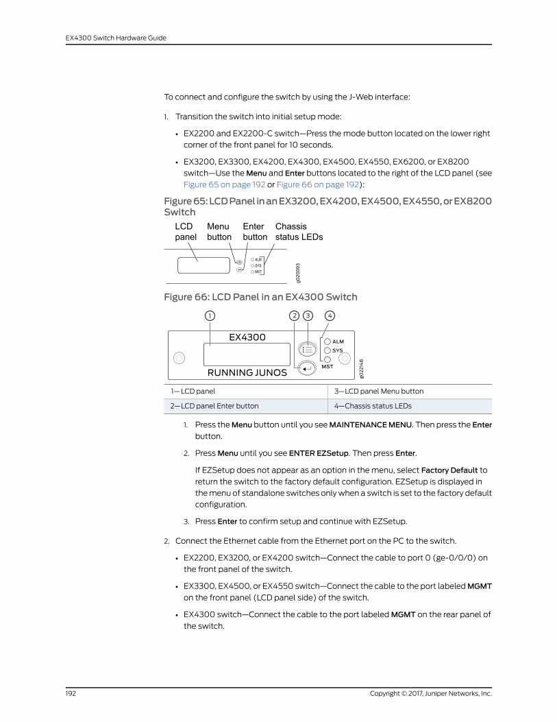
To connect and configure the switch by using the J-Web interface:
1. Transition the switch into initial setupmode:
• EX2200 and EX2200-C switch—Press the mode button located on the lower right
corner of the front panel for 10 seconds.
• EX3200, EX3300, EX4200, EX4300, EX4500, EX4550, EX6200, or EX8200
switch—Use theMenu and Enter buttons located to the right of the LCD panel (see
Figure 65 on page 192 or Figure 66 on page 192):
Figure65:LCDPanel inanEX3200,EX4200,EX4500,EX4550,orEX8200Switch
Figure 66: LCD Panel in an EX4300 Switch
3—1— LCD panel Menu buttonLCD panel
4—2— Chassis status LEDsLCD panel Enter button
1. Press theMenu button until you seeMAINTENANCEMENU. Then press the Enter
button.
2. PressMenu until you see ENTER EZSetup. Then press Enter.
If EZSetup does not appear as an option in the menu, select Factory Default to
return the switch to the factory default configuration. EZSetup is displayed in
themenu of standalone switches onlywhen a switch is set to the factory default
configuration.
3. Press Enter to confirm setup and continue with EZSetup.
2. Connect the Ethernet cable from the Ethernet port on the PC to the switch.
• EX2200, EX3200, or EX4200 switch—Connect the cable to port 0 (ge-0/0/0) on
the front panel of the switch.
• EX3300, EX4500, or EX4550 switch—Connect the cable to the port labeledMGMT
on the front panel (LCD panel side) of the switch.
• EX4300 switch—Connect the cable to the port labeledMGMT on the rear panel of
the switch.
Copyright © 2017, Juniper Networks, Inc.192
EX4300 Switch Hardware Guide
• EX6200switch—Connect thecable tooneof theports labeledMGMTon theSwitch
Fabric and Routing Engine (SRE) module in slot 4 or 5 in an EX6210 switch.
• EX8200 switch—Connect the cable to the port labeledMGMT on the Switch Fabric
and Routing Engine (SRE) module in slot SRE0 in an EX8208 switch or on the
Routing Engine (RE) module in slot RE0 in an EX8216 switch.
These ports are configured as the DHCP server with the default IP address, 192.168.1.1.
The switch can assign an IP address to the management PC in the IP address range
192.168.1.2 through 192.168.1.253.
3. From the PC, open aWeb browser, type http://192.168.1.1 in the address field, andpress Enter.
4. On the J-Web login page, type root as the username, leave the password field blank,and click Login.
5. On the Introduction page, click Next.
6. On the Basic Settings page, modify the hostname, the root password, and date and
time settings:
• Enter the hostname. This is optional.
• Enter a password and reenter the password.
• Specify the time zone.
• Synchronize the date and time settings of the switch with the management PC or
set themmanually by selecting the appropriate option button. This is optional.
Click Next.
7. Use the Management Options page to select the management scenario:
NOTE: OnEX4500, EX6210, and EX8200 switches, only the out-of-bandmanagement option is available.
• In-bandManagement—Use VLAN 'default' for management.
Select this option to configure all data interfaces asmembers of the default VLAN.
Click Next. Specify the management IP address and the default gateway for the
default VLAN.
• In-bandManagement—Create newVLAN formanagement.
Select this option to create amanagement VLAN. Click Next. Specify the VLAN
name, VLAN ID, member interfaces, management IP address, and default gateway
for the new VLAN.
• Out-of-bandManagement—Configuremanagement port.
193Copyright © 2017, Juniper Networks, Inc.
Chapter 14: Performing Initial Configuration
Select this option to configure only the management interface. Click Next. Specify
the IP address and default gateway for the management interface.
8. Click Next.
9. On theManageAccess page, you can select options to enable Telnet, SSH, andSNMP
services. For SNMP, you can configure the read community, location, and contact.
10. Click Next. The Summary screen displays the configured settings.
11. Click Finish. The configuration is committed as the active switch configuration.
NOTE: After the configuration is committed, the connectivity betweenthePCand the switchmight be lost. To renew the connection, release andrenew the IP address by executing the appropriate commands on themanagement PC or by removing and reinserting the Ethernet cable.
12. (For EX4500 switches only) In the CLI, enter the request chassis pic-modeintraconnect operational mode command to set the PICmode to intraconnect.
You can now log in by using the CLI or the J-Web interface to continue configuring the
switch.
If you use the J-Web interface to continue configuring the switch, theWeb session is
redirected to the newmanagement IP address. If the connection cannot bemade, the
J-Web interface displays instructions for starting a J-Web session.
RelatedDocumentation
Connecting and Configuring an EX Series Switch (CLI Procedure) on page 187•
• Installing and Connecting an EX2200 Switch
• Installing and Connecting an EX2300 Switch
• Installing and Connecting an EX3200 Switch
• Installing and Connecting an EX3300 Switch
• Installing and Connecting an EX4200 Switch
• Installing and Connecting an EX4300 Switch on page 137
• Installing and Connecting an EX4500 Switch
• Installing and Connecting an EX4550 Switch
• Installing and Connecting an EX4600 Switch
• Installing and Connecting an EX6210 Switch
• Installing and Connecting an EX8208 Switch
• Installing and Connecting an EX8216 Switch
Copyright © 2017, Juniper Networks, Inc.194
EX4300 Switch Hardware Guide

Configuring the LCD Panel on EX Series Switches (CLI Procedure)
This topic applies to hardware devices in the EX Series product family, which includes
switches and theXRE200External Routing Engine, that support the LCDpanel interface.
The LCD panel on the front panel of EX Series switches displays a variety of information
about the switch in the Statusmenu and provides the Maintenancemenu to enable you
toperformbasic operations suchas initial setupand reboot. Youcandisable thesemenus
or individual menu options if you do not want switch users to use them. You can also set
a custommessage that will be displayed on the panel.
This topic describes:
• Disabling or Enabling Menus and Menu Options on the LCD Panel on page 195
• Configuring a Custom Display Message on page 196
Disabling or EnablingMenus andMenu Options on the LCD Panel
By default, the Maintenancemenu, the Status menu, and the options in those menus in
the LCD panel are enabled. Users can configure and troubleshoot the switch by using
the Maintenancemenu and view certain details about the switch by using the Status
menu.
If you do notwant users to be able to use thosemenus or some of themenu options, you
can disable themenus or individualmenu options. You can reenable themenus ormenu
options.
Issue the show chassis lcdmenu operational mode command to see themenus ormenu
options that are currently enabled.
NOTE: On some platforms, youmust specify an FPC slot number in thesecommands. See the lcd-menu statement for details.
To disable a menu:
[edit]user@switch# set chassis lcd-menumenu-itemmenu-name disable
To enable a menu:
[edit]user@switch# delete chassis lcd-menumenu-itemmenu-name disable
To disable a menu option:
[edit]user@switch# set chassis lcd-menumenu-itemmenu-option disable
195Copyright © 2017, Juniper Networks, Inc.
Chapter 14: Performing Initial Configuration
To enable a menu option:
[edit]user@switch# delete chassis lcd-menumenu-itemmenu-option disable
Configuring a CustomDisplay Message
You can configure the second line of the LCD to display a custommessage temporarily
for 5 minutes or permanently.
To display a custommessage temporarily:
• On an EX3200 switch, a standalone EX3300 switch, a standalone EX4200 switch, a
standaloneEX4300switch, astandaloneEX4500switch, astandaloneEX4550switch,
an EX6200 switch, an EX8200 switch, or an XRE200 External Routing Engine:
user@switch> set chassis displaymessagemessage
• On an EX3300, EX4200, EX4300, EX4500, or EX4550 switch in a Virtual Chassis
configuration:
user@switch> set chassis displaymessagemessage fpc-slot slot-number
To display a custommessage permanently:
• On an EX3200 switch, a standalone EX3300 switch, a standalone EX4200 switch, a
standaloneEX4300switch, astandaloneEX4500switch, astandaloneEX4550switch,
an EX6200 switch, an EX8200 switch, or an XRE200 External Routing Engine:
user@switch> set chassis displaymessagemessage permanent
• On an EX3300, EX4200, EX4300, EX4500, or EX4550 switch in a Virtual Chassis
configuration:
user@switch> set chassis displaymessagemessage fpc-slot slot-number permanent
NOTE: Thebuttonson theLCDpanelaredisabledwhentheLCD isconfiguredto display a custommessage.
To disable the display of the custommessage:
user@switch> clear chassis displaymessage
You can view the custommessage by issuing the show chassis lcd command.
RelatedDocumentation
• LCD Panel in EX3200 Switches
• LCD Panel in EX3300 Switches
• LCD Panel in EX4200 Switches
• LCD Panel in EX4300 Switches on page 27
Copyright © 2017, Juniper Networks, Inc.196
EX4300 Switch Hardware Guide

• LCD Panel in EX4500 Switches
• LCD Panel in EX4550 Switches
• LCD Panel in an EX6200 Switch
• LCD Panel in an EX8200 Switch
• LCD Panel in an XRE200 External Routing Engine
197Copyright © 2017, Juniper Networks, Inc.
Chapter 14: Performing Initial Configuration

Copyright © 2017, Juniper Networks, Inc.198
EX4300 Switch Hardware Guide
PART 4
Installing, Maintaining, and ReplacingComponents
• Replacing Cooling System Component on page 201
• Replacing Power Supply on page 205
• Replacing Uplink Module on page 213
• Replacing Transceiver on page 219
• Maintaining and Replacing Fiber-Optic Cable on page 225
• Contacting Customer Support and Returning the Chassis or Components on page 229
199Copyright © 2017, Juniper Networks, Inc.

Copyright © 2017, Juniper Networks, Inc.200
EX4300 Switch Hardware Guide

CHAPTER 15
Replacing Cooling System Component
• Installing a Fan Module in an EX4300 Switch on page 201
• Removing a Fan Module from an EX4300 Switch on page 203
Installing a FanModule in an EX4300 Switch
Each fanmodule is a hot-removable and hot-insertable field-replaceable unit (FRU)
installed in the rear panel of the switch: You can remove and replace it without powering
off the switch or disrupting switch functions.
CAUTION: Do notmix:
• Fanmoduleswith different airflow labels (AIR IN (AFI)andAIROUT(AFO))
in the same chassis.
• Power supplies with different airflow labels (AIR IN (AFI) and AIR OUT
(AFO)) in the same chassis.
• Power supplies and fanmodules with different airflow labels (AIR IN (AFI)
and AIR OUT (AFO)) in the same chassis.
• AC and DC power supplies in the same chassis.
Before you install a fan module in the switch:
• Ensure you understand how to prevent electrostatic discharge (ESD) damage. See
“Prevention of Electrostatic Discharge Damage” on page 291.
Ensure that you have the following parts and tools available to install a fan module in
the switch chassis:
• ESD grounding strap
• Phillips (+) screwdriver, number 2
201Copyright © 2017, Juniper Networks, Inc.
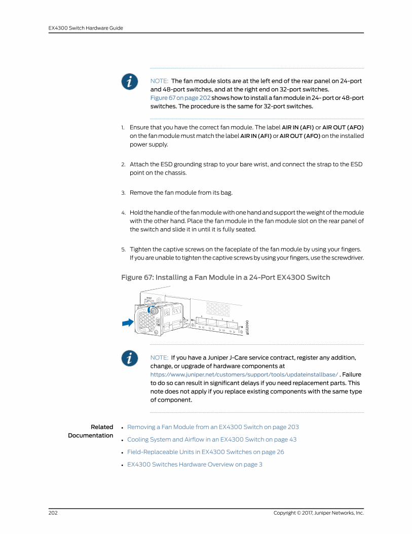
NOTE: The fanmodule slots are at the left end of the rear panel on 24-portand 48-port switches, and at the right end on 32-port switches.Figure67onpage202showshowto install a fanmodule in24-portor48-portswitches. The procedure is the same for 32-port switches.
1. Ensure that you have the correct fanmodule. The label AIR IN (AFI) or AIROUT (AFO)
on the fanmodulemustmatch the labelAIR IN(AFI)orAIROUT(AFO)on the installed
power supply.
2. Attach the ESD grounding strap to your bare wrist, and connect the strap to the ESD
point on the chassis.
3. Remove the fanmodule from its bag.
4. Hold thehandleof the fanmodulewithonehandandsupport theweightof themodule
with the other hand. Place the fanmodule in the fanmodule slot on the rear panel of
the switch and slide it in until it is fully seated.
5. Tighten the captive screws on the faceplate of the fanmodule by using your fingers.
If youareunable to tighten thecaptive screwsbyusing your fingers, use thescrewdriver.
Figure 67: Installing a FanModule in a 24-Port EX4300 Switch
NOTE: If you have a Juniper J-Care service contract, register any addition,change, or upgrade of hardware components athttps://www.juniper.net/customers/support/tools/updateinstallbase/ . Failure
to do so can result in significant delays if you need replacement parts. Thisnote does not apply if you replace existing components with the same typeof component.
RelatedDocumentation
Removing a Fan Module from an EX4300 Switch on page 203•
• Cooling System and Airflow in an EX4300 Switch on page 43
• Field-Replaceable Units in EX4300 Switches on page 26
• EX4300 Switches Hardware Overview on page 3
Copyright © 2017, Juniper Networks, Inc.202
EX4300 Switch Hardware Guide
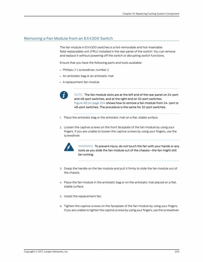
Removing a FanModule from an EX4300 Switch
The fanmodule in EX4300 switches is a hot-removable and hot-insertable
field-replaceable unit (FRU) installed in the rear panel of the switch: You can remove
and replace it without powering off the switch or disrupting switch functions.
Ensure that you have the following parts and tools available:
• Phillips (+) screwdriver, number 2
• An antistatic bag or an antistatic mat
• A replacement fanmodule
NOTE: The fanmodule slots are at the left end of the rear panel on 24-portand 48-port switches, and at the right end on 32-port switches.Figure 68 on page 204 shows how to remove a fanmodule from 24- port or48-port switches. The procedure is the same for 32-port switches.
1. Place the antistatic bag or the antistatic mat on a flat, stable surface.
2. Loosen the captive screws on the front faceplate of the fanmodule by using your
fingers. If you are unable to loosen the captive screws by using your fingers, use the
screwdriver.
WARNING: To prevent injury, do not touch the fan with your hands or anytools as you slide the fanmodule out of the chassis—the fanmight stillbe running.
3. Grasp the handle on the fanmodule and pull it firmly to slide the fanmodule out of
the chassis.
4. Place the fanmodule in the antistatic bag or on the antistatic mat placed on a flat,
stable surface.
5. Install the replacement fan.
6. Tighten the captive screws on the faceplate of the fanmodule by using your fingers.
If youareunable to tighten thecaptive screwsbyusing your fingers, use thescrewdriver.
203Copyright © 2017, Juniper Networks, Inc.
Chapter 15: Replacing Cooling System Component
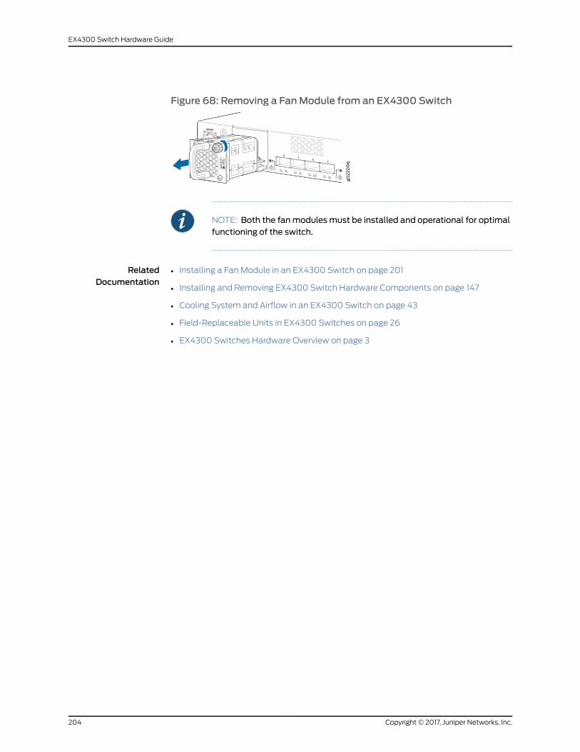
Figure 68: Removing a FanModule from an EX4300 Switch
NOTE: Both the fanmodulesmust be installed and operational for optimalfunctioning of the switch.
RelatedDocumentation
• Installing a Fan Module in an EX4300 Switch on page 201
• Installing and Removing EX4300 Switch Hardware Components on page 147
• Cooling System and Airflow in an EX4300 Switch on page 43
• Field-Replaceable Units in EX4300 Switches on page 26
• EX4300 Switches Hardware Overview on page 3
Copyright © 2017, Juniper Networks, Inc.204
EX4300 Switch Hardware Guide

CHAPTER 16
Replacing Power Supply
• Installing an AC Power Supply in an EX4300 Switch on page 205
• Removing an AC Power Supply from an EX4300 Switch on page 207
• Installing a DC Power Supply in an EX4300 Switch on page 208
• Removing a DC Power Supply from an EX4300 Switch on page 210
Installing an AC Power Supply in an EX4300 Switch
The AC power supply in EX4300 switches is a hot-removable and hot-insertable
field-replaceable unit (FRU) installed in the rear panel of the switch: You can remove
and replace it without powering off the switch or disrupting switch functions.
CAUTION: Do notmix:
• AC and DC power supplies in the same chassis
• Power supplies with different airflow labels (AIR IN (AFI) and AIR OUT
(AFO)) in the same chassis.
• Fanmoduleswith different airflow labels (AIR IN (AFI)andAIROUT(AFO))
in the same chassis.
• Power supplies and fanmodules with different airflow labels (AIR IN (AFI)
and AIR OUT (AFO)) in the same chassis.
Before you install an AC power supply in the switch:
• Ensure you understand how to prevent electrostatic discharge (ESD) damage. See
“Prevention of Electrostatic Discharge Damage” on page 291.
Ensure that you have the following parts and tools available to install the power supply:
• ESD grounding strap
• Phillips (+) screwdriver, number 2
205Copyright © 2017, Juniper Networks, Inc.

NOTE: Each power supply must be connected to a dedicated power sourceoutlet.
The power supply slots are at the right end of the rear panel on 24-port and48-port switches, and at the left end on 32-port switches.Figure 69onpage 206 showshow to install anACpower supply in 24-port or48-port switches. The procedure is the same for 32-port switches.
To install an AC power supply in the switch:
1. Ensure that you have the correct power supply. The label AIR IN (AFI) or AIR OUT
(AFO) on the power supply must match the label AIR IN (AFI) or AIR OUT (AFO) on
the installed fanmodule.
2. Attach the ESD grounding strap to your bare wrist, and connect the strap to the ESD
point on the chassis.
3. If the power supply slot has a cover panel on it, loosen the captive screws on the cover
panel by using your fingers or the screwdriver. Hold the captive screw and gently pull
it outward to remove the cover panel. Save the cover panel for later use.
4. Taking care not to touch power supply pins, leads, or solder connections, remove the
power supply from the bag.
5. Using both hands, place the power supply in the power supply slot on the rear panel
of the switch and slide it in until it is fully seated and the ejector lever fits into place.
Figure 69: Installing an AC Power Supply in an EX4300 Switch
NOTE: If you have a Juniper J-Care service contract, register any addition,change, or upgrade of hardware components athttps://www.juniper.net/customers/support/tools/updateinstallbase/ . Failure
to do so can result in significant delays if you need replacement parts. Thisnote does not apply if you replace existing components with the same typeof component.
Copyright © 2017, Juniper Networks, Inc.206
EX4300 Switch Hardware Guide
RelatedDocumentation
Removing an AC Power Supply from an EX4300 Switch on page 207•
• Connecting AC Power to an EX4300 Switch on page 156
• AC Power Supply in EX4300 Switches on page 49
• AC Power Cord Specifications for an EX4300 Switch on page 100
• EX4300 Switches Hardware Overview on page 3
Removing an AC Power Supply from an EX4300 Switch
The power supplies in EX4300 switches are hot-removable and hot-insertable
field-replaceable units (FRUs) installed in the rear panel of the switch: You can remove
and replace themwithout powering off the switch or disrupting switch functions.
Before you remove a power supply from an EX4300 switch, ensure that you have taken
the necessary precautions to prevent electrostatic discharge (ESD) damage (see
“Prevention of Electrostatic Discharge Damage” on page 291).
Ensure that you have the following parts and tools available to remove a power supply
from an EX4300 switch:
• ESD grounding strap
• Phillips (+) screwdriver, number 2 (not provided)
• Antistatic bag or an antistatic mat
• Replacement power supply or a cover panel for the power supply slot
CAUTION: Werecommendthatyou install eithera replacementpowersupplyoracoverpanel in theemptypowersupply slot topreventchassisoverheatingand dust accumulation.
NOTE: Thepowersupply slotsareat the rightendof the rearpanelon24-portand 48-port switches, and at the left end on 32-port switches.Figure70onpage208showshowto removeanACpowersupply from24-portor 48-port switches. The procedure is the same for 32-port switches.
1. Place the antistatic bag or the antistatic mat on a flat, stable surface.
2. Attach the ESD grounding strap to your bare wrist, and connect the strap to the ESD
point on the chassis.
NOTE: If only one power supply is installed in your EX4300 switch, youneed to power off the switch before removing the power supply.
207Copyright © 2017, Juniper Networks, Inc.
Chapter 16: Replacing Power Supply

3. If the AC power source outlet has a power switch, set it to the OFF (O) position.
4. Gently pull out themale end of the power cord connected to the power source outlet.
5. Remove the power cord from the power supply faceplate by detaching the power
cord retainer and gently pulling out the female end of the power cord connected to
the power supply faceplate.
6. Slide the ejector lever toward the left until the power supply is unseated.
7. Grasp the power supply handle and pull firmly to slide the power supply halfway out
of the chassis.
8. Place one hand under the power supply to support it and slide it completely out of
the chassis. Take care not to touch power supply components, pins, leads, or solder
connections.
9. Place the power supply in the antistatic bag or on the antistatic mat placed on a flat,
stable surface.
10. If you are not replacing the power supply, install the cover panel over the slot.
Figure 70: Removing an AC Power Supply from an EX4300 Switch
RelatedDocumentation
Installing an AC Power Supply in an EX4300 Switch on page 205•
• Installing and Removing EX4300 Switch Hardware Components on page 147
• AC Power Supply Specifications for EX4300 Switches on page 99
• Field-Replaceable Units in EX4300 Switches on page 26
• AC Power Cord Specifications for an EX4300 Switch on page 100
• EX4300 Switches Hardware Overview on page 3
Installing a DC Power Supply in an EX4300 Switch
The DC power supply in EX4300 switches is a hot-removable and hot-insertable
field-replaceable unit (FRU) installed in the rear panel of the switch: You can remove
and replace it without powering off the switch or disrupting switch functions.
Copyright © 2017, Juniper Networks, Inc.208
EX4300 Switch Hardware Guide
CAUTION: Do notmix:
• AC and DC power supplies in the same chassis
• Power supplies with different airflow labels (AIR IN (AFI) and AIR OUT
(AFO)) in the same chassis.
• Fanmoduleswith different airflow labels (AIR IN (AFI)andAIROUT(AFO))
in the same chassis.
• Power supplies and fanmodules with different airflow labels (AIR IN (AFI)
and AIR OUT (AFO)) in the same chassis.
Before you install a DC power supply in the switch:
• Ensure you understand how to prevent electrostatic discharge (ESD) damage. See
“Prevention of Electrostatic Discharge Damage” on page 291.
Ensure that you have the following parts and tools available to install a DC power supply
in the switch chassis:
• ESD grounding strap
• Phillips (+) screwdriver, number 2
NOTE: Each power supply must be connected to a dedicated power sourceoutlet.
The power supply slots are at the right end of the rear panel on 24-port and48-portswitches,andat the leftendon32-portswitches.Figure71onpage210shows how to install a DC power supply in 24-port or 48-port switches. Theprocedure is the same for 32-port switches.
To install a DC power supply in the switch:
1. Ensure that you have the correct power supply. The label AIR IN (AFI) or AIR OUT
(AFO) on the power supply must match the label AIR IN (AFI) or AIR OUT (AFO) on
the installed fanmodule.
2. Attach the ESD grounding strap to your bare wrist, and connect the strap to the ESD
point on the chassis.
3. If the power supply slot has a cover panel on it, loosen the captive screws on the cover
panel by using your fingers or the screwdriver. Hold the captive screw and gently pull
it outward to remove the cover panel. Save the cover panel for later use.
209Copyright © 2017, Juniper Networks, Inc.
Chapter 16: Replacing Power Supply
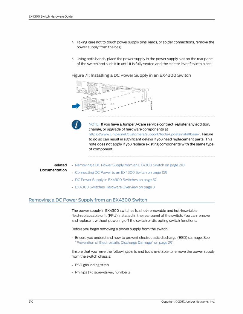
4. Taking care not to touch power supply pins, leads, or solder connections, remove the
power supply from the bag.
5. Using both hands, place the power supply in the power supply slot on the rear panel
of the switch and slide it in until it is fully seated and the ejector lever fits into place.
Figure 71: Installing a DC Power Supply in an EX4300 Switch
NOTE: If you have a Juniper J-Care service contract, register any addition,change, or upgrade of hardware components athttps://www.juniper.net/customers/support/tools/updateinstallbase/ . Failure
to do so can result in significant delays if you need replacement parts. Thisnote does not apply if you replace existing components with the same typeof component.
RelatedDocumentation
Removing a DC Power Supply from an EX4300 Switch on page 210•
• Connecting DC Power to an EX4300 Switch on page 159
• DC Power Supply in EX4300 Switches on page 57
• EX4300 Switches Hardware Overview on page 3
Removing a DC Power Supply from an EX4300 Switch
The power supply in EX4300 switches is a hot-removable and hot-insertable
field-replaceable unit (FRU) installed in the rear panel of the switch: You can remove
and replace it without powering off the switch or disrupting switch functions.
Before you begin removing a power supply from the switch:
• Ensure you understand how to prevent electrostatic discharge (ESD) damage. See
“Prevention of Electrostatic Discharge Damage” on page 291.
Ensure that you have the following parts and tools available to remove the power supply
from the switch chassis:
• ESD grounding strap
• Phillips (+) screwdriver, number 2
Copyright © 2017, Juniper Networks, Inc.210
EX4300 Switch Hardware Guide
• An antistatic bag or an antistatic mat
• Replacement power supply or a cover panel for the power supply slot
CAUTION: Werecommendthatyou install eithera replacementpowersupplyoracoverpanel in theemptypowersupply slot topreventchassisoverheatingand dust accumulation.
NOTE: Thepowersupply slotsareat the rightendof the rearpanelon24-portand 48-port switches, and at the left end on 32-port switches.Figure 72 on page 212 shows how to remove a DC power supply from 24-portor 48-port switches. The procedure is the same for 32-port switches.
1. Place the antistatic bag or the antistatic mat on a flat, stable surface.
2. Attach the ESD grounding strap to your bare wrist, and connect the strap to the ESD
point on the chassis.
3. Make sure that the voltage across the DC power source cables leads is 0 V and that
there is no chance that the cables might become active during the removal process.
4. Remove the plastic cover from the input terminals by sliding the cover either to the
left or right.
5. Unscrew the locking screws counterclockwise by using the screwdriver.
6. Remove the cable lugs from the input DC terminals.
7. Slide the ejector lever toward the left until the power supply is unseated.
8. Grasp the power supply handle and pull firmly to slide the power supply halfway out
of the chassis.
9. Taking care not to touch power supply pins, leads, or solder connections, place one
hand under the power supply to support it. Grasp the power supply handle with your
other hand and pull the power supply completely out of the chassis.
10. Place the power supply in the antistatic bag or on the antistatic mat placed on a flat,
stable surface.
11. If you are not replacing the power supply, install the cover panel over the slot.
211Copyright © 2017, Juniper Networks, Inc.
Chapter 16: Replacing Power Supply

Figure 72: Removing a DC Power Supply from an EX4300 Switch
RelatedDocumentation
• Installing a DC Power Supply in an EX4300 Switch on page 208
• DC Power Supply in EX4300 Switches on page 57
• EX4300 Switches Hardware Overview on page 3
Copyright © 2017, Juniper Networks, Inc.212
EX4300 Switch Hardware Guide
CHAPTER 17
Replacing Uplink Module
• Installing an Uplink Module in an EX4300 Switch on page 213
• Removing an Uplink Module from an EX4300 Switch on page 215
Installing an Uplink Module in an EX4300 Switch
You can install an uplink module in the front panel of an EX4300 switch. The uplink
module in EX4300 switches is a hot-removable and hot-insertable unit (FRU): You can
remove and replace it without powering off the switch.
NOTE: If you have set an uplinkmodule port as a Virtual Chassis port (VCP),removing the uplink module breaks the setting. Youmust reset the port as aVCP after you replace themodule. See Setting an Uplink Port on an EX SeriesSwitch as a Virtual Chassis Port (CLI Procedure).
Before you begin installing an uplink module in the switch:
• Ensure that you have taken the necessary precautions to prevent ESD damage (see
“Prevention of Electrostatic Discharge Damage” on page 291).
Ensure that you have the following parts and tools available:
• Electrostatic discharge (ESD) grounding strap (If a grounding strap is not available,
followthealternativegroundingmethoddescribed inStep 1of the followingprocedure.)
• Phillips (+) screwdriver, number 2
213Copyright © 2017, Juniper Networks, Inc.
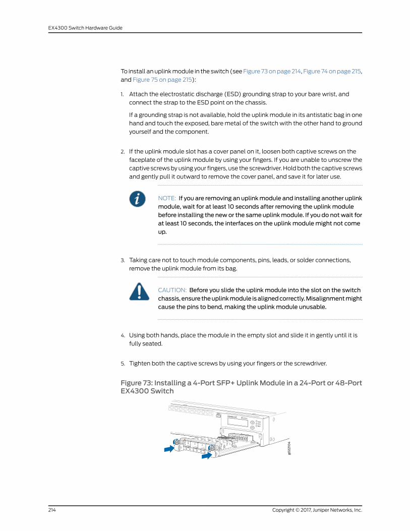
To install anuplinkmodule in the switch (seeFigure 73onpage214, Figure 74onpage215,
and Figure 75 on page 215):
1. Attach the electrostatic discharge (ESD) grounding strap to your bare wrist, and
connect the strap to the ESD point on the chassis.
If a grounding strap is not available, hold the uplinkmodule in its antistatic bag in one
hand and touch the exposed, bare metal of the switch with the other hand to ground
yourself and the component.
2. If the uplink module slot has a cover panel on it, loosen both captive screws on the
faceplate of the uplink module by using your fingers. If you are unable to unscrew the
captive screwsbyusing your fingers, use the screwdriver. Holdboth the captive screws
and gently pull it outward to remove the cover panel, and save it for later use.
NOTE: If you are removing an uplinkmodule and installing another uplinkmodule, wait for at least 10 seconds after removing the uplink modulebefore installing the newor the sameuplinkmodule. If you do notwait forat least 10 seconds, the interfaces on the uplink modulemight not comeup.
3. Taking care not to touchmodule components, pins, leads, or solder connections,
remove the uplink module from its bag.
CAUTION: Before you slide the uplink module into the slot on the switchchassis, ensure theuplinkmodule isalignedcorrectly.Misalignmentmightcause the pins to bend, making the uplink module unusable.
4. Using both hands, place the module in the empty slot and slide it in gently until it is
fully seated.
5. Tighten both the captive screws by using your fingers or the screwdriver.
Figure 73: Installing a 4-Port SFP+UplinkModule in a 24-Port or 48-PortEX4300 Switch
Copyright © 2017, Juniper Networks, Inc.214
EX4300 Switch Hardware Guide
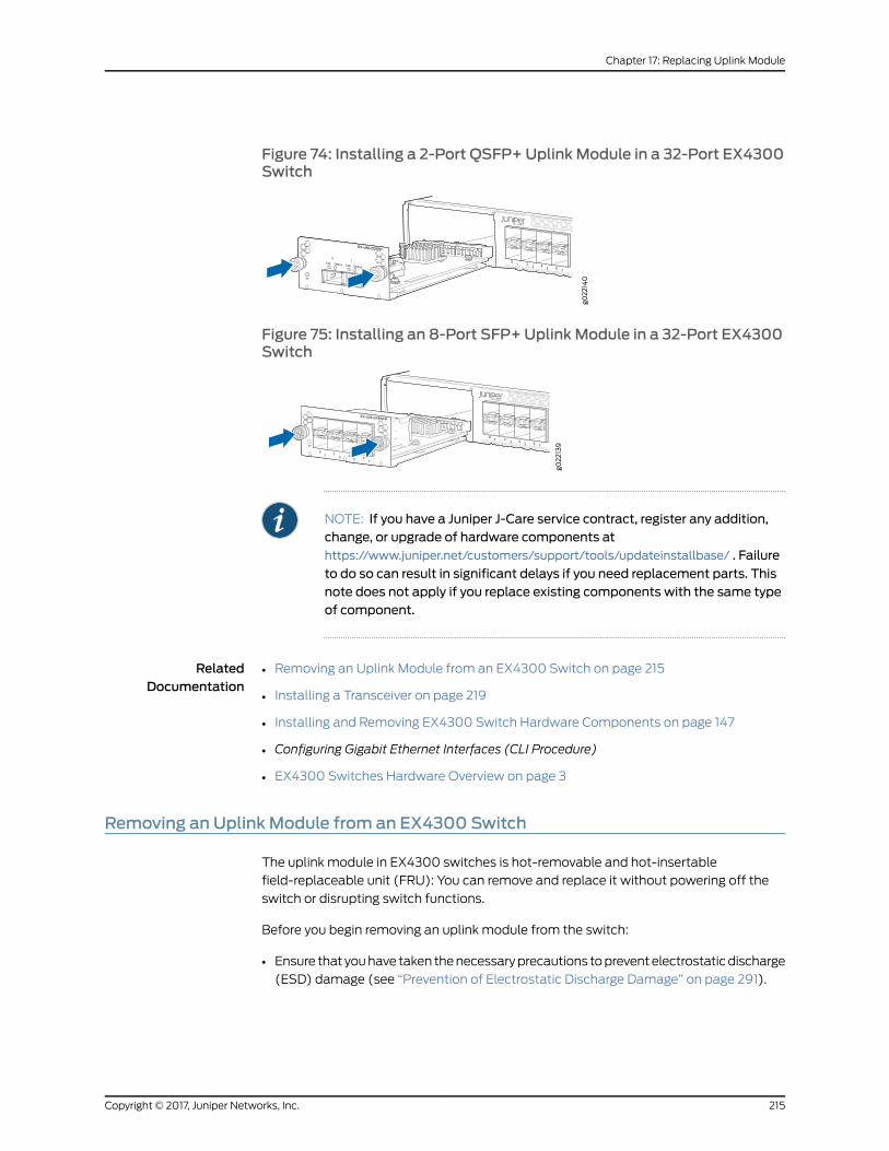
Figure 74: Installing a 2-Port QSFP+ Uplink Module in a 32-Port EX4300Switch
Figure 75: Installing an 8-Port SFP+ Uplink Module in a 32-Port EX4300Switch
NOTE: If you have a Juniper J-Care service contract, register any addition,change, or upgrade of hardware components athttps://www.juniper.net/customers/support/tools/updateinstallbase/ . Failure
to do so can result in significant delays if you need replacement parts. Thisnote does not apply if you replace existing components with the same typeof component.
RelatedDocumentation
Removing an Uplink Module from an EX4300 Switch on page 215•
• Installing a Transceiver on page 219
• Installing and Removing EX4300 Switch Hardware Components on page 147
• Configuring Gigabit Ethernet Interfaces (CLI Procedure)
• EX4300 Switches Hardware Overview on page 3
Removing an Uplink Module from an EX4300 Switch
The uplink module in EX4300 switches is hot-removable and hot-insertable
field-replaceable unit (FRU): You can remove and replace it without powering off the
switch or disrupting switch functions.
Before you begin removing an uplink module from the switch:
• Ensure that youhave taken thenecessaryprecautions topreventelectrostaticdischarge
(ESD) damage (see “Prevention of Electrostatic Discharge Damage” on page 291).
215Copyright © 2017, Juniper Networks, Inc.
Chapter 17: Replacing Uplink Module
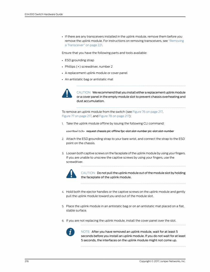
• If there are any transceivers installed in the uplink module, remove them before you
remove the uplink module. For instructions on removing transceivers, see “Removing
a Transceiver” on page 221.
Ensure that you have the following parts and tools available:
• ESD grounding strap
• Phillips (+) screwdriver, number 2
• A replacement uplink module or cover panel
• An antistatic bag or antistatic mat
CAUTION: Werecommendthatyou installeithera replacementuplinkmoduleor a cover panel in the emptymodule slot to prevent chassis overheating anddust accumulation.
To remove an uplink module from the switch (see Figure 76 on page 217,
Figure 77 on page 217, and Figure 78 on page 217):
1. Take the uplink module offline by issuing the following CLI command:
user@switch> request chassis pic offline fpc-slot slot-number pic-slot slot-number
2. Attach the ESD grounding strap to your bare wrist, and connect the strap to the ESD
point on the chassis.
3. Loosenbothcaptive screwson the faceplateof theuplinkmodulebyusing your fingers.
If you are unable to unscrew the captive screws by using your fingers, use the
screwdriver.
CAUTION: Donotpull theuplinkmoduleoutof themoduleslotbyholdingthe faceplate of the uplink module.
4. Hold both the ejector handles or the captive screws on the uplink module and gently
pull the uplink module toward you and out of the module slot.
5. Place the uplink module in an antistatic bag or on an antistatic mat placed on a flat,
stable surface.
6. If you are not replacing the uplink module, install the cover panel over the slot.
NOTE: After you have removed an uplink module, wait for at least 5seconds before you install an uplinkmodule. If you do notwait for at least5 seconds, the interfaces on the uplink modulemight not come up.
Copyright © 2017, Juniper Networks, Inc.216
EX4300 Switch Hardware Guide
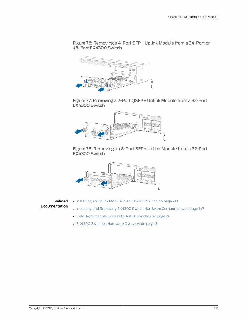
Figure 76: Removing a 4-Port SFP+ Uplink Module from a 24-Port or48-Port EX4300 Switch
g022
09
7
Figure 77: Removing a 2-Port QSFP+ Uplink Module from a 32-PortEX4300 Switch
Figure 78: Removing an 8-Port SFP+ Uplink Module from a 32-PortEX4300 Switch
g022
141
RelatedDocumentation
• Installing an Uplink Module in an EX4300 Switch on page 213
• Installing and Removing EX4300 Switch Hardware Components on page 147
• Field-Replaceable Units in EX4300 Switches on page 26
• EX4300 Switches Hardware Overview on page 3
217Copyright © 2017, Juniper Networks, Inc.
Chapter 17: Replacing Uplink Module

Copyright © 2017, Juniper Networks, Inc.218
EX4300 Switch Hardware Guide
CHAPTER 18
Replacing Transceiver
• Installing a Transceiver on page 219
• Removing a Transceiver on page 221
Installing a Transceiver
The transceivers for Juniper Networks devices are hot-removable and hot-insertable
field-replaceable units (FRUs): You can remove and replace themwithout powering off
the device or disrupting the device functions.
NOTE: After you insert a transceiver or after you change themedia-typeconfiguration, wait for 6 seconds for the interface to display operationalcommands.
NOTE: We recommend that you use only optical transceivers and opticalconnectors purchased from Juniper Networks with your Juniper Networksdevice.
CAUTION: If you face a problem running a Juniper Networks device that usesa third-partyopticor cable, the JuniperNetworksTechnicalAssistanceCenter(JTAC) can help you diagnose the source of the problem. Your JTAC engineermight recommendthatyoucheckthethird-partyopticorcableandpotentiallyreplace it with an equivalent Juniper Networks optic or cable that is qualifiedfor the device.
NOTE: OnanEX3200switch, if you install a transceiver ina 1-GigabitEthernetuplink module port, a corresponding network port from the last four built-inports is disabled. For example, if you install a transceiver in theuplinkmoduleport 3 (ge-0/1/2), then the built-in port 23 (ge-0/0/22) is disabled. The
disabled port is not listed in the output of show interface commands.
219Copyright © 2017, Juniper Networks, Inc.
Before you begin installing a transceiver in a device, ensure that you have taken the
necessary precautions for safe handling of lasers (see “Laser and LED Safety Guidelines
andWarnings” on page 279).
Ensure that you have a rubber safety cap available to cover the transceiver.
Figure 79 on page 221 shows how to install a QSFP+ transceiver. The procedure is the
same for all types of transceivers except the CFP transceivers.
To install a transceiver:
CAUTION: To prevent electrostatic discharge (ESD) damage to thetransceiver, do not touch the connector pins at the end of the transceiver.
1. Remove the transceiver from its bag.
2. Check to see whether the transceiver is covered with a rubber safety cap. If it is not,
cover the transceiver with a rubber safety cap.
WARNING: Do not leave a fiber-optic transceiver uncovered exceptwheninserting or removing a cable. The rubber safety cap keeps the port cleanand prevents accidental exposure to laser light.
3. If the port in which you want to install the transceiver is covered with a dust cover,
remove the dust cover and save it in case you need to cover the port later. If you are
hot-swappinga transceiver,wait for at least 10 secondsafter removing the transceiver
from the port before installing a new transceiver.
4. Using both hands, carefully place the transceiver in the empty port. The connectors
must face the chassis.
CAUTION: Before you slide the transceiver into the port, ensure that thetransceiver is aligned correctly. Misalignmentmight cause the pins tobend, making the transceiver unusable.
5. Slide the transceiver in gently until it is fully seated. If you are installing a CFP
transceiver, tighten the captive screws on the transceiver by using your fingers.
6. Remove the rubber safety cap when you are ready to connect the cable to the
transceiver.
Copyright © 2017, Juniper Networks, Inc.220
EX4300 Switch Hardware Guide
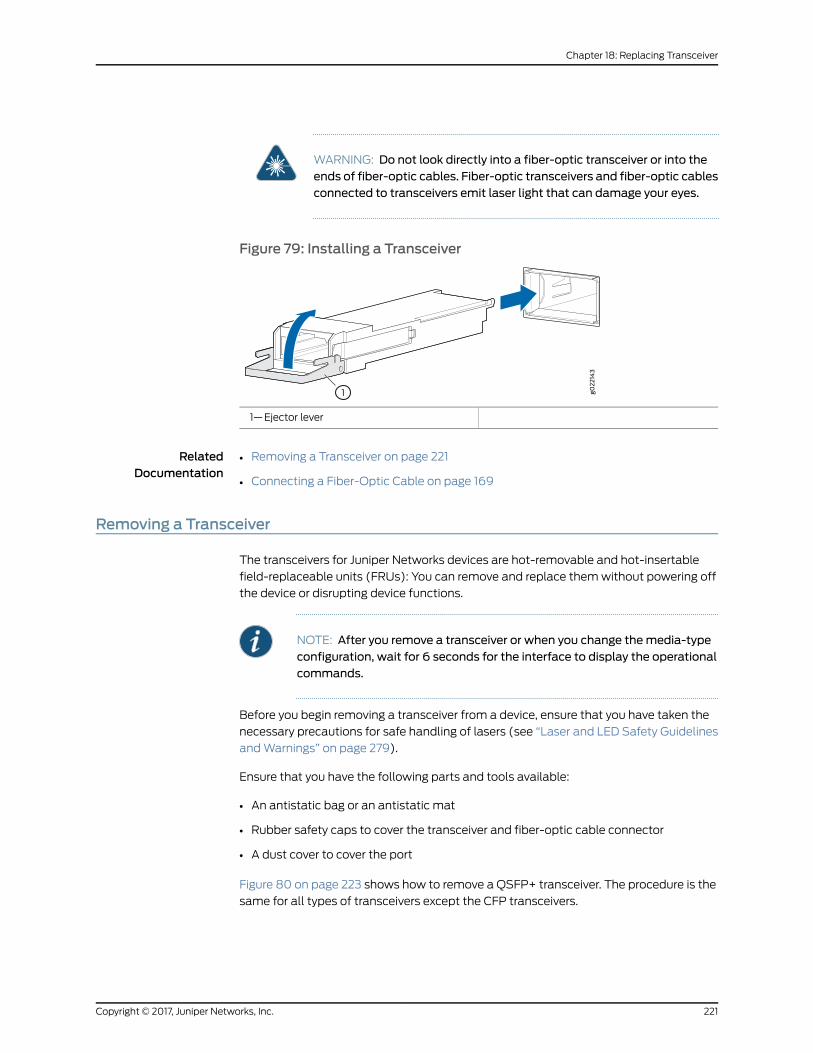
WARNING: Do not look directly into a fiber-optic transceiver or into theends of fiber-optic cables. Fiber-optic transceivers and fiber-optic cablesconnected to transceivers emit laser light that can damage your eyes.
Figure 79: Installing a Transceiver
1—Ejector lever
RelatedDocumentation
Removing a Transceiver on page 221•
• Connecting a Fiber-Optic Cable on page 169
Removing a Transceiver
The transceivers for Juniper Networks devices are hot-removable and hot-insertable
field-replaceable units (FRUs): You can remove and replace themwithout powering off
the device or disrupting device functions.
NOTE: After you remove a transceiver or when you change themedia-typeconfiguration, wait for 6 seconds for the interface to display the operationalcommands.
Before you begin removing a transceiver from a device, ensure that you have taken the
necessary precautions for safe handling of lasers (see “Laser and LED Safety Guidelines
andWarnings” on page 279).
Ensure that you have the following parts and tools available:
• An antistatic bag or an antistatic mat
• Rubber safety caps to cover the transceiver and fiber-optic cable connector
• A dust cover to cover the port
Figure 80 on page 223 shows how to remove a QSFP+ transceiver. The procedure is the
same for all types of transceivers except the CFP transceivers.
221Copyright © 2017, Juniper Networks, Inc.
Chapter 18: Replacing Transceiver
To remove a transceiver from a device:
1. Place the antistatic bag or antistatic mat on a flat, stable surface.
2. Label the cable connected to the transceiver so that you can reconnect it correctly.
WARNING: Do not look directly into a fiber-optic transceiver or into theends of fiber-optic cables. Fiber-optic transceivers and fiber-optic cablesconnected to transceivers emit laser light that can damage your eyes.
WARNING: Do not leave a fiber-optic transceiver uncovered exceptwheninserting or removing a cable. The rubber safety cap keeps the port cleanand prevents accidental exposure to laser light.
CAUTION: Do not bend fiber-optic cables beyond their minimum bendradius.Anarcsmaller thana few inches indiametercandamagethecablesand cause problems that are difficult to diagnose.
3. Remove the cable connected to the transceiver (see “Disconnecting a Fiber-Optic
Cable fromaDevice”onpage226).Cover the transceiverandtheendofeach fiber-optic
cable connector with a rubber safety cap immediately after disconnecting the
fiber-optic cables.
Copyright © 2017, Juniper Networks, Inc.222
EX4300 Switch Hardware Guide
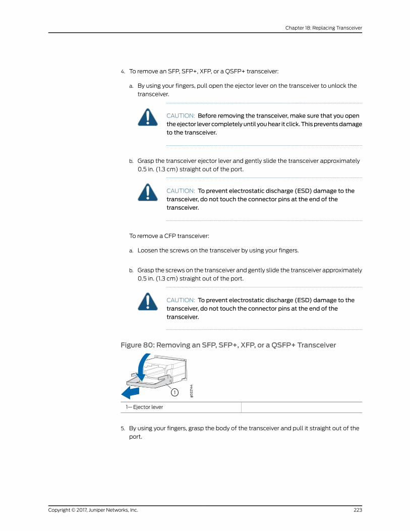
4. To remove an SFP, SFP+, XFP, or a QSFP+ transceiver:
a. By using your fingers, pull open the ejector lever on the transceiver to unlock the
transceiver.
CAUTION: Before removing the transceiver, make sure that you opentheejector lever completelyuntil youhear it click.Thispreventsdamageto the transceiver.
b. Grasp the transceiver ejector lever and gently slide the transceiver approximately
0.5 in. (1.3 cm) straight out of the port.
CAUTION: To prevent electrostatic discharge (ESD) damage to thetransceiver, do not touch the connector pins at the end of thetransceiver.
To remove a CFP transceiver:
a. Loosen the screws on the transceiver by using your fingers.
b. Grasp the screws on the transceiver and gently slide the transceiver approximately
0.5 in. (1.3 cm) straight out of the port.
CAUTION: To prevent electrostatic discharge (ESD) damage to thetransceiver, do not touch the connector pins at the end of thetransceiver.
Figure 80: Removing an SFP, SFP+, XFP, or a QSFP+ Transceiver
1—Ejector lever
5. By using your fingers, grasp the body of the transceiver and pull it straight out of the
port.
223Copyright © 2017, Juniper Networks, Inc.
Chapter 18: Replacing Transceiver

6. Place the transceiver in the antistatic bag or on the antistatic mat placed on a flat,
stable surface.
7. Place the dust cover over the empty port.
RelatedDocumentation
• Installing a Transceiver on page 219
Copyright © 2017, Juniper Networks, Inc.224
EX4300 Switch Hardware Guide
CHAPTER 19
Maintaining and Replacing Fiber-OpticCable
• Connecting a Fiber-Optic Cable on page 225
• Disconnecting a Fiber-Optic Cable from a Device on page 226
• Maintaining Fiber-Optic Cables on page 227
Connecting a Fiber-Optic Cable
Before you begin connecting a fiber-optic cable to an optical transceiver installed in a
device, ensure that you have taken the necessary precautions for safe handling of lasers
(see “Laser and LED Safety Guidelines andWarnings” on page 279).
To connect a fiber-optic cable to an optical transceiver installed in a device:
WARNING: Do not look directly into a fiber-optic transceiver or into the endsof fiber-opticcables.Fiber-optic transceiversandfiber-opticcablesconnectedto transceivers emit laser light that can damage your eyes.
1. If the fiber-optic cable connector is coveredwith a rubber safety cap, remove the cap.
Save the cap.
2. Remove the rubber safety cap from the optical transceiver. Save the cap.
3. Insert the cable connector into the optical transceiver (see Figure 57 on page 169).
225Copyright © 2017, Juniper Networks, Inc.
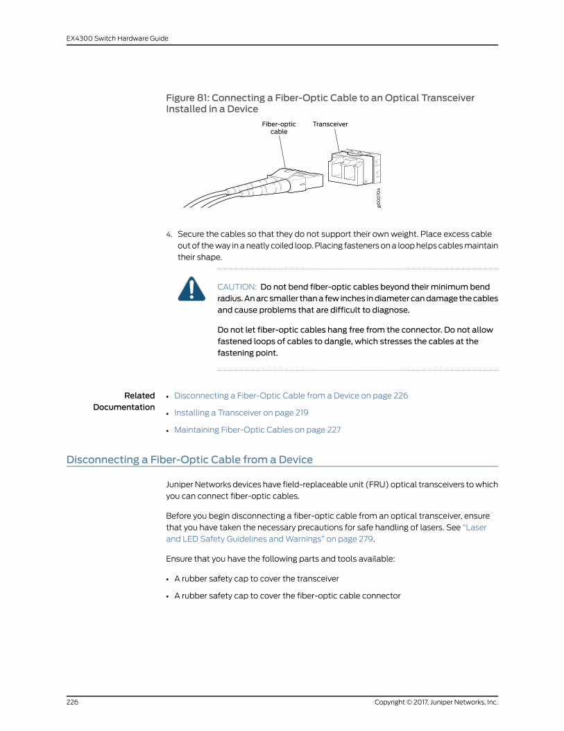
Figure 81: Connecting a Fiber-Optic Cable to an Optical TransceiverInstalled in a Device
4. Secure the cables so that they do not support their own weight. Place excess cable
outof theway inaneatly coiled loop.Placing fastenersona loophelps cablesmaintain
their shape.
CAUTION: Do not bend fiber-optic cables beyond their minimum bendradius.Anarcsmaller thana few inches indiametercandamagethecablesand cause problems that are difficult to diagnose.
Do not let fiber-optic cables hang free from the connector. Do not allowfastened loops of cables to dangle, which stresses the cables at thefastening point.
RelatedDocumentation
Disconnecting a Fiber-Optic Cable from a Device on page 226•
• Installing a Transceiver on page 219
• Maintaining Fiber-Optic Cables on page 227
Disconnecting a Fiber-Optic Cable from a Device
Juniper Networks devices have field-replaceable unit (FRU) optical transceivers towhich
you can connect fiber-optic cables.
Before you begin disconnecting a fiber-optic cable from an optical transceiver, ensure
that you have taken the necessary precautions for safe handling of lasers. See “Laser
and LED Safety Guidelines andWarnings” on page 279.
Ensure that you have the following parts and tools available:
• A rubber safety cap to cover the transceiver
• A rubber safety cap to cover the fiber-optic cable connector
Copyright © 2017, Juniper Networks, Inc.226
EX4300 Switch Hardware Guide
To disconnect a fiber-optic cable from an optical transceiver installed in the device:
1. Disable theport inwhich the transceiver is installedby issuing the followingcommand:
[edit interfaces]user@device# set interface-name disable
WARNING: Do not look directly into a fiber-optic transceiver or into theends of fiber-optic cables. Fiber-optic transceivers and fiber-optic cablesconnected to transceivers emit laser light that can damage your eyes.
2. Carefully unplug the fiber-optic cable connector from the transceiver.
3. Cover the transceiver with a rubber safety cap.
WARNING: Do not leave a fiber-optic transceiver uncovered exceptwheninserting or removing a cable. The rubber safety cap keeps the port cleanand prevents accidental exposure to laser light.
4. Cover the fiber-optic cable connector with the rubber safety cap.
RelatedDocumentation
Connecting a Fiber-Optic Cable on page 169•
• Removing a Transceiver on page 221
• Maintaining Fiber-Optic Cables on page 227
Maintaining Fiber-Optic Cables
Fiber-optic cables connect to optical transceivers that are installed in Juniper Networks
devices.
Tomaintain fiber-optic cables:
• When you unplug a fiber-optic cable from a transceiver, place rubber safety caps over
the transceiver and on the end of the cable.
• Anchor fiber-optic cables to prevent stress on the connectors. When attaching a
fiber-optic cable to a transceiver, be sure to secure the fiber-optic cable so that it does
not support its own weight as it hangs to the floor. Never let a fiber-optic cable hang
free from the connector.
• Avoidbending fiber-opticcablesbeyondtheirminimumbend radius.Bending fiber-optic
cables into arcs smaller than a few inches in diameter can damage the cables and
cause problems that are difficult to diagnose.
227Copyright © 2017, Juniper Networks, Inc.
Chapter 19: Maintaining and Replacing Fiber-Optic Cable

• Frequentpluggingandunpluggingof fiber-optic cables inandoutofoptical instruments
can damage the instruments, which are expensive to repair. Attach a short fiber
extension to the optical equipment. Any wear and tear due to frequent plugging and
unplugging is then absorbed by the short fiber extension, which is easier and less
expensive to replace than the instruments.
• Keep fiber-optic cable connections clean. Microdeposits of oil and dust in the canal of
the transceiver or cable connector can cause loss of light, reduction in signal power,
and possibly intermittent problems with the optical connection.
• To clean the transceiver canal, use an appropriate fiber-cleaning device such as
RIFOCSFiberOpticAdaptorCleaningWands(partnumber946).Followthedirections
in the cleaning kit you use.
• After cleaning the transceiver, make sure that the connector tip of the fiber-optic
cable is clean. Use only an approved alcohol-free fiber-optic cable cleaning kit such
as the Opptex Cletop-S®
Fiber Cleaner. Follow the directions in the cleaning kit you
use.
RelatedDocumentation
• Connecting a Fiber-Optic Cable on page 169
• Laser and LED Safety Guidelines andWarnings on page 279
Copyright © 2017, Juniper Networks, Inc.228
EX4300 Switch Hardware Guide

CHAPTER 20
Contacting Customer Support andReturning the Chassis or Components
• Returning an EX4300 Switch or Component for Repair or Replacement on page 229
• Locating the Serial Number on an EX4300 Switch or Component on page 230
• Contacting Customer Support to Obtain Return Material Authorization on page 234
• Packing an EX4300 Switch or Component for Shipping on page 234
Returning an EX4300 Switch or Component for Repair or Replacement
If you need to return an EX4300 switch or hardware component to Juniper Networks for
repair or replacement, follow this procedure:
1. Determine the serial number of the component. For instructions, see “Locating the
Serial Number on an EX4300 Switch or Component” on page 230.
2. Obtain an Return Materials Authorization (RMA) number from JTAC as described in
“Contacting Customer Support toObtain ReturnMaterial Authorization” on page 234.
NOTE: Donot return any component to JuniperNetworks unless youhavefirst obtained an RMA number. Juniper Networks reserves the right torefuse shipments that do not have an RMA. Refused shipments arereturned to the customer through collect freight.
3. Pack theswitchor component for shippingasdescribed in “PackinganEX4300Switch
or Component for Shipping” on page 234.
Formore information about return and repair policies, see the customer support page at
http://www.juniper.net/support/guidelines.html .
RelatedDocumentation
EX4300 Switches Hardware Overview on page 3•
229Copyright © 2017, Juniper Networks, Inc.
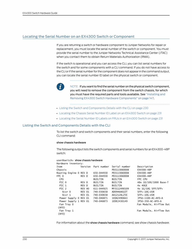
Locating the Serial Number on an EX4300 Switch or Component
If you are returning a switch or hardware component to Juniper Networks for repair or
replacement, youmust locate the serial number of the switch or component. Youmust
provide the serial number to the Juniper Networks Technical Assistance Center (JTAC)
when you contact them to obtain Return Materials Authorization (RMA).
If the switch is operational and you can access the CLI, you can list serial numbers for
the switch and for some components with a CLI command. If you do not have access to
theCLI or if the serial number for thecomponentdoesnotappear in thecommandoutput,
you can locate the serial number ID label on the physical switch or component.
NOTE: If youwant to findtheserialnumberonthephysicalswitchcomponent,you will need to remove the component from the switch chassis, for whichyoumust have the required parts and tools available. See “Installing andRemoving EX4300 Switch Hardware Components” on page 147.
• Listing the Switch and Components Details with the CLI on page 230
• Locating the Chassis Serial Number ID Label on an EX4300 Switch on page 231
• Locating the Serial Number ID Labels on FRUs in an EX4300 Switch on page 231
Listing the Switch and Components Details with the CLI
To list the switch and switch components and their serial numbers, enter the following
CLI command:
show chassis hardware
The followingoutput lists the switchcomponentsandserial numbers for anEX4300-48P
switch:
user@switch> show chassis hardwareHardware inventory:Item Version Part number Serial number DescriptionChassis PD3113060008 EX4300–48PRouting Engine 0 REV D 650-044930 PD3113060008 EX4300-48PFPC 0 REV D 650-044930 PD3113060008 EX4300-48P CPU BUILTIN BUILTIN FPC CPU PIC 0 REV D BUILTIN BUILTIN 48x 10/100/1000 Base-T PIC 1 REV D BUILTIN BUILTIN 4x 40GE PIC 2 REV A0 611-044925 MY3112490109 4x 1G/10G SFP/SFP+ Xcvr 0 REV 01 740-030658 AD0946A02ZT SFP+-10G-USR Xcvr 1 REV 01 740-030658 AA1212ALZ5E SFP+-10G-USR Power Supply 0 REV 01 740-046871 1EDA2490663 JPSU-1100-AC-AFO-A Power Supply 1 REV 01 740-046873 1EDE2430149 JPSU-350-AC-AFO-A Fan Tray 0 Fan Module, Airflow Out (AFO) Fan Tray 1 Fan Module, Airflow Out (AFO)
For information about the showchassis hardware command, see show chassis hardware.
Copyright © 2017, Juniper Networks, Inc.230
EX4300 Switch Hardware Guide
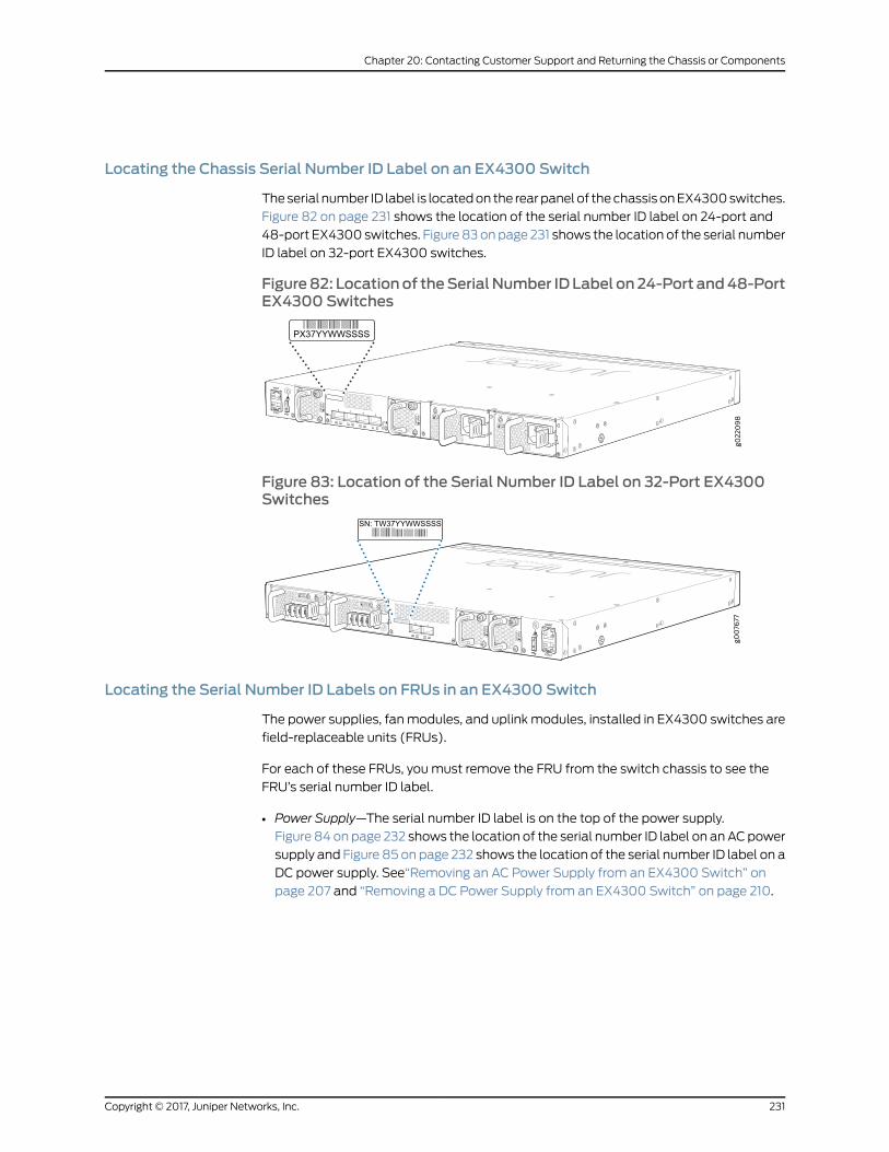
Locating the Chassis Serial Number ID Label on an EX4300 Switch
Theserial number ID label is locatedon the rearpanelof thechassisonEX4300switches.
Figure 82 on page 231 shows the location of the serial number ID label on 24-port and
48-port EX4300 switches. Figure 83onpage 231 shows the location of the serial number
ID label on 32-port EX4300 switches.
Figure82: Locationof theSerialNumber IDLabel on24-Port and48-PortEX4300 Switches
Figure 83: Location of the Serial Number ID Label on 32-Port EX4300Switches
Locating the Serial Number ID Labels on FRUs in an EX4300 Switch
The power supplies, fanmodules, and uplinkmodules, installed in EX4300 switches are
field-replaceable units (FRUs).
For each of these FRUs, youmust remove the FRU from the switch chassis to see the
FRU’s serial number ID label.
• Power Supply—The serial number ID label is on the top of the power supply.
Figure 84 on page 232 shows the location of the serial number ID label on anACpower
supply and Figure 85 on page 232 shows the location of the serial number ID label on a
DC power supply. See“Removing an AC Power Supply from an EX4300 Switch” on
page 207 and “Removing a DC Power Supply from an EX4300 Switch” on page 210.
231Copyright © 2017, Juniper Networks, Inc.
Chapter 20: Contacting Customer Support and Returning the Chassis or Components
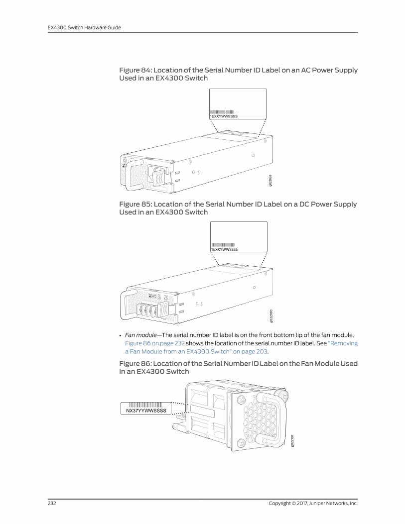
Figure84: Location of theSerial Number ID Label on anACPowerSupplyUsed in an EX4300 Switch
g022
099
Figure 85: Location of the Serial Number ID Label on a DC Power SupplyUsed in an EX4300 Switch
• Fan module—The serial number ID label is on the front bottom lip of the fanmodule.
Figure 86onpage 232 shows the location of the serial number ID label. See “Removing
a Fan Module from an EX4300 Switch” on page 203.
Figure86:Locationof theSerialNumber IDLabelontheFanModuleUsedin an EX4300 Switch
Copyright © 2017, Juniper Networks, Inc.232
EX4300 Switch Hardware Guide

• Uplinkmodule—Theserial number ID label is on the circuit board. Figure87onpage233
shows the location of the serial number ID label on the QSFP+ uplink module,
Figure 88 on page 233 shows the location of the serial number ID label on the 4-port
SFP+uplinkmodule, andFigure89onpage233shows the locationof the serial number
ID label on the 8-port SFP+ uplink module. See “Removing an Uplink Module from an
EX4300 Switch” on page 215.
Figure 87: Location of the Serial Number ID Label on the QSFP+UplinkModule
S/N: RY3113470002
Figure 88: Location of the Serial Number ID Label on the 4-Port SFP+Uplink Module
g022
102
Figure 89: Location of the Serial Number ID Label on the 8-Port SFP+Uplink Module
g022
146
S/N: RX3114020039
RelatedDocumentation
Contacting Customer Support to Obtain Return Material Authorization on page 234•
• Returning an EX4300 Switch or Component for Repair or Replacement on page 229
233Copyright © 2017, Juniper Networks, Inc.
Chapter 20: Contacting Customer Support and Returning the Chassis or Components
Contacting Customer Support to Obtain ReturnMaterial Authorization
If you are returning a device or hardware component to Juniper Networks for repair or
replacement,obtainaReturnMaterialAuthorization(RMA)number fromJuniperNetworks
Technical Assistance Center (JTAC).
After locating the serial number of thedeviceor hardware component youwant to return,
open a Case with Juniper Networks Technical Assistance Center (JTAC) on theWeb or
by telephone.
Before you request an RMA number from JTAC, be prepared to provide the following
information:
• Your existing case number, if you have one
• Serial number of the component
• Your name, organization name, telephone number, fax number, and shipping address
• Details of the failure or problem
• Type of activity being performed on the device when the problem occurred
• Configuration data displayed by one or more show commands
You can contact JTAC 24 hours a day, seven days a week on theWeb or by telephone:
• Case Manager at CSC: http://www.juniper.net/cm/
• Telephone: +1-888-314-JTAC1-888-314-5822, toll free in U.S., Canada, and Mexico
NOTE: For international or direct-dial options in countries without toll freenumbers, see http://www.juniper.net/support/requesting-support.html.
If you are contacting JTAC by telephone, enter your 12-digit case number followed by the
pound (#) key for an existing case, or press the star (*) key to be routed to the next
available support engineer.
The support representative validates your request and issues an RMA number for return
of the component.
RelatedDocumentation
Prevention of Electrostatic Discharge Damage on page 291•
Packing an EX4300 Switch or Component for Shipping
If you are returning an EX4300 switch or component to Juniper Networks for repair or
replacement, pack the item as described in this topic.
Before you begin packing the switch or component, ensure you have:
Copyright © 2017, Juniper Networks, Inc.234
EX4300 Switch Hardware Guide

• Followedall the steps listed in “ContactingCustomerSupport toObtainReturnMaterial
Authorization” on page 234.
• Retrieved the original shipping carton and packing materials. Contact your JTAC
representative if you do not have these materials, to learn about approved packing
materials.See “ContactingCustomerSupport toObtainReturnMaterialAuthorization”
on page 234.
• Ensure you understand how to prevent electrostatic discharge (ESD) damage. See
“Prevention of Electrostatic Discharge Damage” on page 291.
This topic describes:
1. Packing an EX4300 Switch for Shipping on page 235
2. Packing EX4300 Switch Components for Shipping on page 236
Packing an EX4300 Switch for Shipping
If you need to transport the switch to another location or return the switch to Juniper
Networks, youneed topack theswitchsecurely in itsoriginalpackaging topreventdamage
during transportation.
Before you pack the switch:
1. On the console or other management device connected to the switch, enter the CLI
operationalmodeand issue the followingcommandtoshutdowntheswitchsoftware:
user@switch> request system halt
Wait until a message appears on the console confirming that the operating system
has halted.
2. Disconnect power from the switch by performing one of the following:
• If the power source outlet has a power switch, set it to the OFF (0) position.
• If the power source outlet does not have a power switch, gently pull out the male
end of the power cord connected to the power source outlet.
3. Remove thecables that connect the switch toall external devices. See “Disconnecting
a Fiber-Optic Cable from a Device” on page 226.
4. Remove all optical transceivers installed in the switch. See “Removing a Transceiver”
on page 221.
Ensure that you have the following parts and tools available to pack the switch:
• Phillips (+) screwdriver, number 2
• The original switch packing material (cardboard box, accessory box and its contents,
and foam padding)
235Copyright © 2017, Juniper Networks, Inc.
Chapter 20: Contacting Customer Support and Returning the Chassis or Components
• ESD grounding strap
• Antistatic bag
CAUTION: Do not pack the switch in anything except its original container orthe switchmight be damaged in transit.
To pack the switch:
1. If the switch is installed in a rack or cabinet, have one person support the weight of
the switch while another person unscrews and removes the mounting screws.
2. Remove the switch from the rack or cabinet and place the switch on a flat, stable
surface.
3. Use the screwdriver to remove the rack-mounting brackets from the switch chassis.
4. Place the switch in an antistatic bag.
5. Place the bottom portion of the packaging foam in the shipping carton.
6. Place the switch inside the cavity in the bottom packaging foam.
7. Place the top portion of the packaging foam on top of the switch.
8. If youare returningaccessories or field-replaceable units (FRUs)with the switch, pack
themas instructed in “PackingEX4300SwitchComponents forShipping”onpage236.
9. Place the accessory box vertically by the rear endof the chassis in the shipping carton.
10. Close the top of the cardboard shipping box and seal it with packing tape.
11. Write the RMA number on the exterior of the box to ensure proper tracking.
Packing EX4300 Switch Components for Shipping
To pack the switch components, follow the instructions here.
Ensure that you have the following parts and tools available:
• Antistatic bag, one for each component
• ESD grounding strap
Copyright © 2017, Juniper Networks, Inc.236
EX4300 Switch Hardware Guide
CAUTION: Do not stack switch components. Return individual componentsin separate boxes if they do not fit together on one level in the shipping box.
To pack the switch components:
• Place individual components in antistatic bags.
• Use the original packingmaterials if they are available. If the original packingmaterials
are not available, ensure the component is adequately packed to prevent damage
during transit. The packingmaterial you usemust be able to support the weight of the
component.
• Ensure that the components are adequately protected by wrapping themwell with
packing materials. Pack the component in an oversized box (if the original box is not
available) with extra packing material around the unit so that the component is
prevented frommoving around inside the box.
• Securely tape the box closed.
• Write the RMA number on the exterior of the box to ensure proper tracking.
RelatedDocumentation
• Returning an EX4300 Switch or Component for Repair or Replacement on page 229
• Unpacking an EX4300 Switch on page 133
237Copyright © 2017, Juniper Networks, Inc.
Chapter 20: Contacting Customer Support and Returning the Chassis or Components

Copyright © 2017, Juniper Networks, Inc.238
EX4300 Switch Hardware Guide
PART 5
Troubleshooting
• Alarms and Syslog Messages on page 241
• Troubleshooting Switch Components on page 253
239Copyright © 2017, Juniper Networks, Inc.

Copyright © 2017, Juniper Networks, Inc.240
EX4300 Switch Hardware Guide

CHAPTER 21
Alarms and Syslog Messages
• Understanding Alarm Types and Severity Levels on EX Series Switches on page 241
• Chassis Component Alarm Conditions on EX4300 Switches on page 242
• Checking Active Alarms with the J-Web Interface on page 246
• Monitoring System Log Messages on page 247
Understanding Alarm Types and Severity Levels on EX Series Switches
NOTE: This topic applies only to the J-Web Application package.
Alarms alert you to conditions thatmight prevent normal operation of the switch. Before
monitoring alarms on a Juniper Networks EX Series Ethernet switch, become familiar
with the terms defined in Table 81 on page 241.
Table 81: Alarm Terms
DefinitionTerm
Signal alerting you to conditions that might prevent normal operation. On a switch, the alarmsignal is the ALM LED lit on the front of the chassis.
alarm
Failure event that triggers an alarm.alarm condition
Seriousness of the alarm. If the Alarm (ALM) LED is red, this indicates amajor alarm. If the AlarmLED is yellow, this indicates aminor alarm. If the Alarm LED is unlit, there is no alarm or the switchis halted.
alarm severity
Preset alarm triggered by a physical condition on the switch such as a power supply failure,excessive component temperature, or media failure.
chassis alarm
Preset alarm triggered by amissing rescue configuration or failure to install a license for a licensedsoftware feature.
NOTE: On EX6200 switches, a system alarm can be triggered by an internal link error.
system alarm
Alarm Types
241Copyright © 2017, Juniper Networks, Inc.
The switch supports these alarms:
• Chassis alarms indicatea failureon the switchoroneof its components. Chassis alarms
are preset and cannot bemodified.
• System alarms indicate amissing rescue configuration. System alarms are preset and
cannot bemodified, although you can configure them to appear automatically in the
J-Web interface display or the CLI display.
Alarm Severity Levels
Alarms on switches have two severity levels:
• Major (red)—Indicates a critical situation on the switch that has resulted from one of
the following conditions. A red alarm condition requires immediate action.
• One or more hardware components have failed.
• One or more hardware components have exceeded temperature thresholds.
• An alarm condition configured on an interface has triggered a critical warning.
• Minor (yellow or amber)—Indicates a noncritical condition on the switch that, if left
unchecked, might cause an interruption in service or degradation in performance. A
yellow alarm condition requires monitoring or maintenance.
A missing rescue configuration generates a yellow system alarm.
RelatedDocumentation
Checking Active Alarms with the J-Web Interface on page 246•
• Dashboard for EX Series Switches on page 65
Chassis Component Alarm Conditions on EX4300 Switches
This topic describes the chassis component alarm conditions on EX4300 switches.
Table 82 on page 243 lists the alarms that the chassis components can generate on
EX4300 switches, their severity levels, and the actions you can take to respond to them.
Copyright © 2017, Juniper Networks, Inc.242
EX4300 Switch Hardware Guide
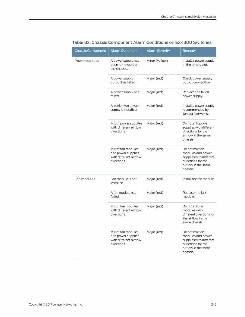
Table 82: Chassis Component Alarm Conditions on EX4300 Switches
RemedyAlarm SeverityAlarm ConditionChassisComponent
Install a power supplyin the empty slot.
Minor (yellow)A power supply hasbeen removed fromthe chassis.
Power supplies
Check power supplyoutput connection.
Major (red)A power supplyoutput has failed.
Replace the failedpower supply.
Major (red)A power supply hasfailed.
Install a power supplyrecommended byJuniper Networks.
Major (red)An unknown powersupply is installed.
Do not mix powersupplieswithdifferentdirections for theairflow in the samechassis.
Major (red)Mix of power supplieswith different airflowdirections.
Do not mix fanmodules and powersupplieswithdifferentdirections for theairflow in the samechassis.
Major (red)Mix of fan modulesand power supplieswith different airflowdirections.
Install the fanmodule.Major (red)Fanmodule is notinstalled.
Fanmodules
Replace the fanmodule.
Major (red)A fanmodule hasfailed.
Do not mix fanmodules withdifferentdirections forthe airflow in thesame chassis.
Major (red)Mix of fan moduleswith different airflowdirections.
Do not mix fanmodules and powersupplieswithdifferentdirections for theairflow in the samechassis.
Major (red)Mix of fan modulesand power supplieswith different airflowdirections.
243Copyright © 2017, Juniper Networks, Inc.
Chapter 21: Alarms and Syslog Messages

Table 82: Chassis Component Alarm Conditions on EX4300Switches (continued)
RemedyAlarm SeverityAlarm ConditionChassisComponent
• Check the fan.
• Open a supportcaseusing theCaseManager link athttp://www.juniper.net/support/or call1-888-314-5822(toll-freewithin theUnited States andCanada) or1-408-745-9500(from outside theUnited States).
Minor (yellow)The temperatureinside the chassisreaches the yellowalarm limit.
Temperature
• Check the fan.
• Open a supportcaseusing theCaseManager link athttp://www.juniper.net/support/or call1-888-314-5822(toll-freewithin theUnited States andCanada) or1-408-745-9500(from outside theUnited States).
Major (red)The temperatureinside the chassisreaches the red alarmlimit.
Open a support caseusing the CaseManager link athttp://www.juniper.net/support/or call1-888-314-5822(toll-free within theUnited States andCanada) or1-408-745-9500(from outside theUnited States).
Major (red)The temperaturesensor has failed.
Copyright © 2017, Juniper Networks, Inc.244
EX4300 Switch Hardware Guide
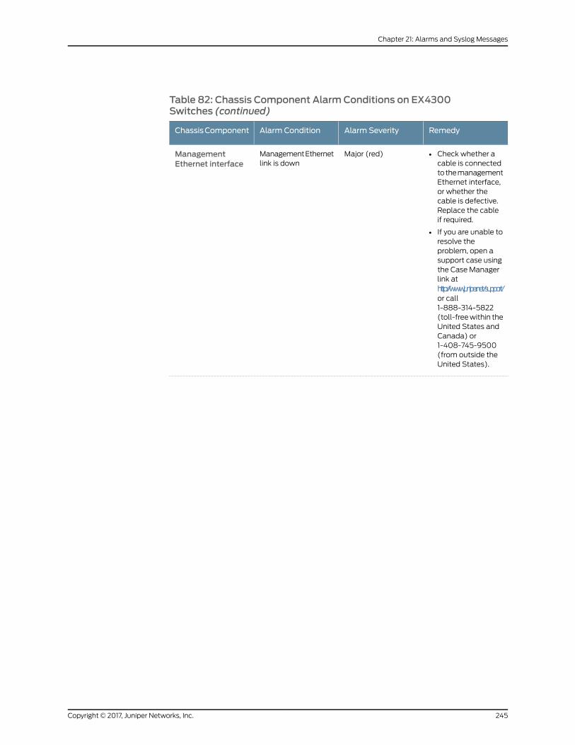
Table 82: Chassis Component Alarm Conditions on EX4300Switches (continued)
RemedyAlarm SeverityAlarm ConditionChassisComponent
• Check whether acable is connectedtothemanagementEthernet interface,or whether thecable is defective.Replace the cableif required.
• If you are unable toresolve theproblem, open asupport case usingthe Case Managerlink athttp://www.juniper.net/support/or call1-888-314-5822(toll-freewithin theUnited States andCanada) or1-408-745-9500(from outside theUnited States).
Major (red)ManagementEthernetlink is down
ManagementEthernet interface
245Copyright © 2017, Juniper Networks, Inc.
Chapter 21: Alarms and Syslog Messages
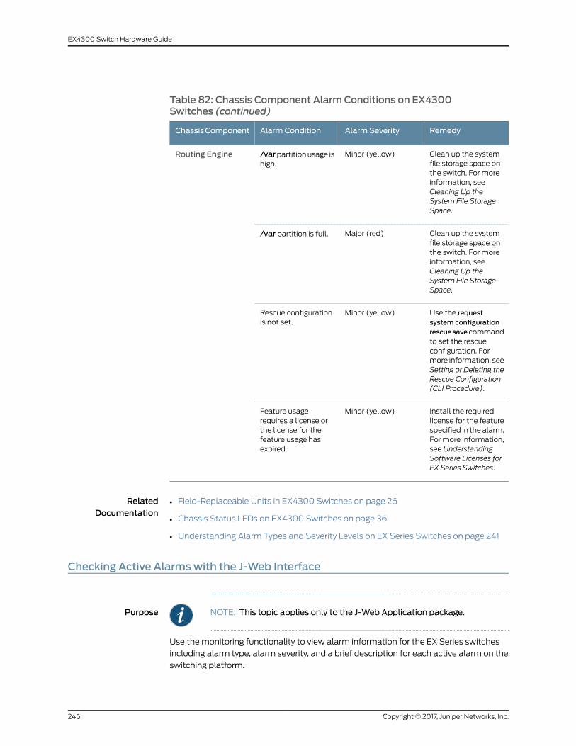
Table 82: Chassis Component Alarm Conditions on EX4300Switches (continued)
RemedyAlarm SeverityAlarm ConditionChassisComponent
Clean up the systemfile storage space onthe switch. For moreinformation, seeCleaning Up theSystem File StorageSpace.
Minor (yellow)/varpartitionusage ishigh.
Routing Engine
Clean up the systemfile storage space onthe switch. For moreinformation, seeCleaning Up theSystem File StorageSpace.
Major (red)/var partition is full.
Use the requestsystem configurationrescuesavecommandto set the rescueconfiguration. Formore information, seeSetting or Deleting theRescue Configuration(CLI Procedure).
Minor (yellow)Rescue configurationis not set.
Install the requiredlicense for the featurespecified in the alarm.For more information,see UnderstandingSoftware Licenses forEX Series Switches.
Minor (yellow)Feature usagerequires a license orthe license for thefeature usage hasexpired.
RelatedDocumentation
Field-Replaceable Units in EX4300 Switches on page 26•
• Chassis Status LEDs on EX4300 Switches on page 36
• Understanding Alarm Types and Severity Levels on EX Series Switches on page 241
Checking Active Alarmswith the J-Web Interface
Purpose NOTE: This topic applies only to the J-Web Application package.
Use themonitoring functionality to view alarm information for the EX Series switches
including alarm type, alarm severity, and a brief description for each active alarm on the
switching platform.
Copyright © 2017, Juniper Networks, Inc.246
EX4300 Switch Hardware Guide

Action To view the active alarms:
1. SelectMonitor > Events and Alarms > View Alarms in the J-Web interface.
2. Select an alarm filter based on alarm type, severity, description, and date range.
3. Click Go.
All the alarmsmatching the filter are displayed.
NOTE: When the switch is reset, the active alarms are displayed.
Meaning Table 83 on page 247 lists the alarm output fields.
Table 83: Summary of Key AlarmOutput Fields
ValuesField
Category of the alarm:
• Chassis—Indicates an alarm condition on the chassis (typically an environmental alarm such asone related to temperature).
• System—Indicates an alarm condition in the system.
Type
Alarm severity—either major (red) or minor (yellow).Severity
Brief synopsis of the alarm.Description
Date and time when the failure was detected.Time
RelatedDocumentation
Monitoring System Log Messages on page 247•
• Dashboard for EX Series Switches on page 65
• Understanding Alarm Types and Severity Levels on EX Series Switches on page 241
Monitoring System LogMessages
Purpose NOTE: This topic applies only to the J-Web Application package.
Use themonitoring functionality to filter and view system logmessages for EX Series
switches.
247Copyright © 2017, Juniper Networks, Inc.
Chapter 21: Alarms and Syslog Messages
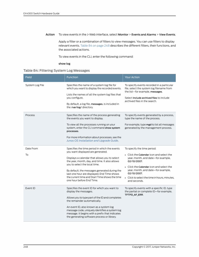
Action To view events in the J-Web interface, selectMonitor > Events and Alarms > View Events.
Apply a filter or a combination of filters to viewmessages. You can use filters to display
relevant events. Table 84 on page 248 describes the different filters, their functions, and
the associated actions.
To view events in the CLI, enter the following command:
show log
Table 84: Filtering System LogMessages
Your ActionFunctionField
To specify events recorded in a particularfile, select the system log filename fromthe list—for example,messages.
Select Include archived files to includearchived files in the search.
Specifies the name of a system log file forwhich youwant to display the recorded events.
Lists the names of all the system log files thatyou configure.
By default, a log file,messages, is included inthe /var/log/ directory.
System Log File
To specify events generated by a process,type the name of the process.
For example, typemgd to list allmessagesgenerated by the management process.
Specifies the name of the process generatingthe events you want to display.
To view all the processes running on yoursystem, enter the CLI command show systemprocesses.
Formore information about processes, see theJunos OS Installation and Upgrade Guide.
Process
To specify the time period:
• Click the Calendar icon and select theyear, month, and date—for example,02/10/2007.
• Click the Calendar icon and select theyear, month, and date—for example,02/10/2007.
• Click toselect the time inhours,minutes,and seconds.
Specifies the time period in which the eventsyou want displayed are generated.
Displays a calendar that allows you to selectthe year, month, day, and time. It also allowsyou to select the local time.
By default, themessages generated during thelast one hour are displayed. End Time showsthecurrent timeandStartTimeshows the timeone hour before End Time.
Date From
To
To specify events with a specific ID, typethe partial or complete ID—for example,TFTPD_AF_ERR.
Specifies the event ID for which you want todisplay the messages.
Allowsyou to typepartof the IDandcompletesthe remainder automatically.
An event ID, also known as a system logmessage code, uniquely identifies a system logmessage. It begins with a prefix that indicatesthe generating software process or library.
Event ID
Copyright © 2017, Juniper Networks, Inc.248
EX4300 Switch Hardware Guide
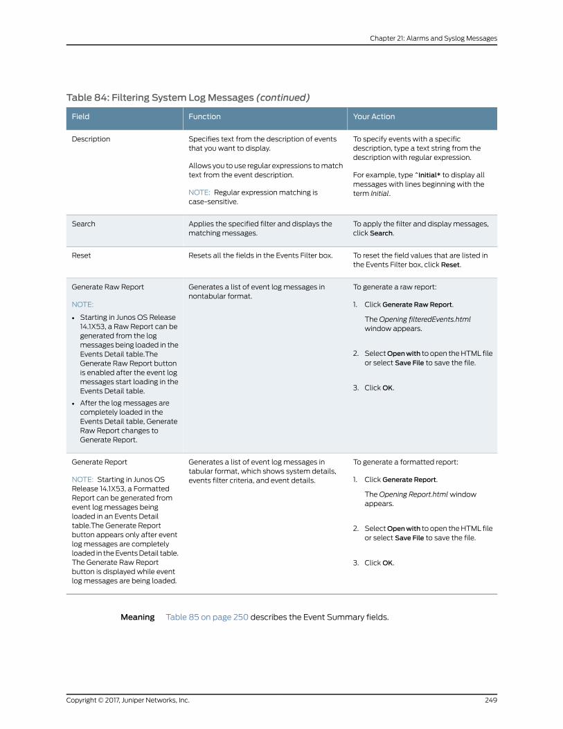
Table 84: Filtering System LogMessages (continued)
Your ActionFunctionField
To specify events with a specificdescription, type a text string from thedescription with regular expression.
For example, type ^Initial* to display allmessages with lines beginning with theterm Initial.
Specifies text from the description of eventsthat you want to display.
Allows you to use regular expressions tomatchtext from the event description.
NOTE: Regular expression matching iscase-sensitive.
Description
To apply the filter and display messages,click Search.
Applies the specified filter and displays thematching messages.
Search
To reset the field values that are listed inthe Events Filter box, click Reset.
Resets all the fields in the Events Filter box.Reset
To generate a raw report:
1. Click Generate RawReport.
TheOpening filteredEvents.htmlwindow appears.
2. SelectOpenwith to open theHTML fileor select Save File to save the file.
3. ClickOK.
Generates a list of event log messages innontabular format.
Generate Raw Report
NOTE:
• Starting in Junos OS Release14.1X53, a Raw Report can begenerated from the logmessages being loaded in theEvents Detail table.TheGenerate Raw Report buttonis enabled after the event logmessages start loading in theEvents Detail table.
• After the log messages arecompletely loaded in theEvents Detail table, GenerateRaw Report changes toGenerate Report.
To generate a formatted report:
1. Click Generate Report.
TheOpening Report.htmlwindowappears.
2. SelectOpenwith to open theHTML fileor select Save File to save the file.
3. ClickOK.
Generates a list of event log messages intabular format, which shows system details,events filter criteria, and event details.
Generate Report
NOTE: Starting in Junos OSRelease 14.1X53, a FormattedReport can be generated fromevent log messages beingloaded in an Events Detailtable.The Generate Reportbutton appears only after eventlog messages are completelyloaded in theEventsDetail table.The Generate Raw Reportbutton is displayed while eventlog messages are being loaded.
Meaning Table 85 on page 250 describes the Event Summary fields.
249Copyright © 2017, Juniper Networks, Inc.
Chapter 21: Alarms and Syslog Messages
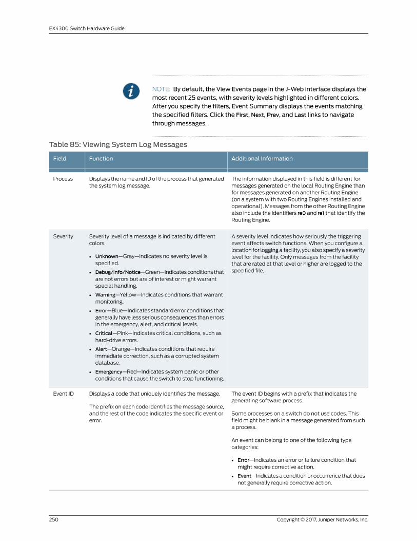
NOTE: By default, the View Events page in the J-Web interface displays themost recent 25 events, with severity levels highlighted in different colors.After you specify the filters, Event Summary displays the events matchingthe specified filters. Click the First, Next, Prev, and Last links to navigate
throughmessages.
Table 85: Viewing System LogMessages
Additional InformationFunctionField
The information displayed in this field is different formessages generated on the local Routing Engine thanfor messages generated on another Routing Engine(on a systemwith two Routing Engines installed andoperational). Messages from the other Routing Enginealso include the identifiers re0 and re1 that identify theRouting Engine.
Displays thenameand IDof theprocess that generatedthe system logmessage.
Process
A severity level indicates how seriously the triggeringevent affects switch functions. When you configure alocation for logging a facility, youalso specify a severitylevel for the facility. Only messages from the facilitythat are rated at that level or higher are logged to thespecified file.
Severity level of a message is indicated by differentcolors.
• Unknown—Gray—Indicates no severity level isspecified.
• Debug/Info/Notice—Green—Indicatesconditions thatare not errors but are of interest or might warrantspecial handling.
• Warning—Yellow—Indicates conditions that warrantmonitoring.
• Error—Blue—Indicatesstandarderror conditions thatgenerallyhave lessseriousconsequences thanerrorsin the emergency, alert, and critical levels.
• Critical—Pink—Indicates critical conditions, such ashard-drive errors.
• Alert—Orange—Indicates conditions that requireimmediate correction, such as a corrupted systemdatabase.
• Emergency—Red—Indicates system panic or otherconditions that cause the switch to stop functioning.
Severity
The event ID begins with a prefix that indicates thegenerating software process.
Some processes on a switch do not use codes. Thisfieldmight be blank in amessage generated fromsucha process.
An event can belong to one of the following typecategories:
• Error—Indicates an error or failure condition thatmight require corrective action.
• Event—Indicatesaconditionor occurrence thatdoesnot generally require corrective action.
Displays a code that uniquely identifies the message.
The prefix on each code identifies themessage source,and the rest of the code indicates the specific event orerror.
Event ID
Copyright © 2017, Juniper Networks, Inc.250
EX4300 Switch Hardware Guide

Table 85: Viewing System LogMessages (continued)
Additional InformationFunctionField
Displays a more detailed explanation of the message.EventDescription
Displays the time at which the message was logged.Time
Release History Table DescriptionRelease
Starting in Junos OS Release 14.1X53, a Raw Report can be generated fromthe log messages being loaded in the Events Detail table.
14.1X53
Starting in JunosOSRelease 14.1X53, a Formatted Report can be generatedfrom event log messages being loaded in an Events Detail table.
14.1X53
RelatedDocumentation
• Checking Active Alarms with the J-Web Interface on page 246
• Understanding Alarm Types and Severity Levels on EX Series Switches on page 241
251Copyright © 2017, Juniper Networks, Inc.
Chapter 21: Alarms and Syslog Messages

Copyright © 2017, Juniper Networks, Inc.252
EX4300 Switch Hardware Guide

CHAPTER 22
Troubleshooting Switch Components
• Troubleshooting PoE Voltage Injection Failure in EX2300, EX3400, or EX4300 Switch
Models with PoE Capability on page 253
• Troubleshooting Temperature Alarms in EX Series Switches on page 253
Troubleshooting PoE Voltage Injection Failure in EX2300, EX3400, or EX4300SwitchModels with PoE Capability
Problem Description:Devices that drawpower fromEX2300, EX3400, or EX4300 switchmodels
with Power over Ethernet (PoE) capability do not get power from those switches. The
problem persists after rebooting the switches or upgrading to the latest version of Junos
OS.
Environment: EX2300, EX3400, or EX4300 switch models with PoE capability areconnected to EX2200, EX3200, or EX4200 switch models with PoE capability by using
RJ-45 network ports.
Solution When you connect EX2300, EX3400, or EX4300 switch models with PoE capability to
EX2200, EX3200, or EX4200 switchmodels with PoE capability by using RJ-45 network
ports, disable PoE on all the RJ-45 network ports used to connect the switches using the
command:
user@device> set poe interface interface-name disable
RelatedDocumentation
Understanding PoE on EX Series Switches•
Troubleshooting Temperature Alarms in EX Series Switches
Problem Description: The EX Series switch generates a temperature alarm FPC 0 EX-PFE1 Temp
Too Hot.
Cause Temperature sensors in the chassis monitor the temperature of the chassis. The switch
raises an alarm if a fan fails or if the temperature of the chassis exceeds permissible
levels.
253Copyright © 2017, Juniper Networks, Inc.
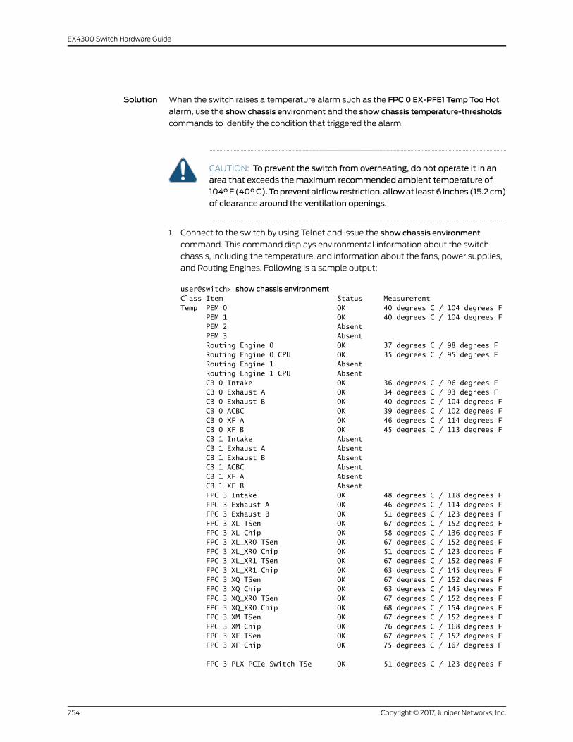
Solution When the switch raises a temperature alarm such as the FPC 0 EX-PFE1 Temp Too Hot
alarm, use the show chassis environment and the show chassis temperature-thresholds
commands to identify the condition that triggered the alarm.
CAUTION: To prevent the switch from overheating, do not operate it in anarea that exceeds themaximum recommended ambient temperature of104°F(40°C).Topreventairflowrestriction, allowat least6 inches(15.2cm)of clearance around the ventilation openings.
1. Connect to the switch by using Telnet and issue the show chassis environment
command. This command displays environmental information about the switch
chassis, including the temperature, and information about the fans, power supplies,
and Routing Engines. Following is a sample output:
user@switch> show chassis environmentClass Item Status MeasurementTemp PEM 0 OK 40 degrees C / 104 degrees F PEM 1 OK 40 degrees C / 104 degrees F PEM 2 Absent PEM 3 Absent Routing Engine 0 OK 37 degrees C / 98 degrees F Routing Engine 0 CPU OK 35 degrees C / 95 degrees F Routing Engine 1 Absent Routing Engine 1 CPU Absent CB 0 Intake OK 36 degrees C / 96 degrees F CB 0 Exhaust A OK 34 degrees C / 93 degrees F CB 0 Exhaust B OK 40 degrees C / 104 degrees F CB 0 ACBC OK 39 degrees C / 102 degrees F CB 0 XF A OK 46 degrees C / 114 degrees F CB 0 XF B OK 45 degrees C / 113 degrees F CB 1 Intake Absent CB 1 Exhaust A Absent CB 1 Exhaust B Absent CB 1 ACBC Absent CB 1 XF A Absent CB 1 XF B Absent FPC 3 Intake OK 48 degrees C / 118 degrees F FPC 3 Exhaust A OK 46 degrees C / 114 degrees F FPC 3 Exhaust B OK 51 degrees C / 123 degrees F FPC 3 XL TSen OK 67 degrees C / 152 degrees F FPC 3 XL Chip OK 58 degrees C / 136 degrees F FPC 3 XL_XR0 TSen OK 67 degrees C / 152 degrees F FPC 3 XL_XR0 Chip OK 51 degrees C / 123 degrees F FPC 3 XL_XR1 TSen OK 67 degrees C / 152 degrees F FPC 3 XL_XR1 Chip OK 63 degrees C / 145 degrees F FPC 3 XQ TSen OK 67 degrees C / 152 degrees F FPC 3 XQ Chip OK 63 degrees C / 145 degrees F FPC 3 XQ_XR0 TSen OK 67 degrees C / 152 degrees F FPC 3 XQ_XR0 Chip OK 68 degrees C / 154 degrees F FPC 3 XM TSen OK 67 degrees C / 152 degrees F FPC 3 XM Chip OK 76 degrees C / 168 degrees F FPC 3 XF TSen OK 67 degrees C / 152 degrees F FPC 3 XF Chip OK 75 degrees C / 167 degrees F
FPC 3 PLX PCIe Switch TSe OK 51 degrees C / 123 degrees F
Copyright © 2017, Juniper Networks, Inc.254
EX4300 Switch Hardware Guide

FPC 3 PLX PCIe Switch Chi OK 54 degrees C / 129 degrees F FPC 3 Aloha FPGA 0 TSen OK 51 degrees C / 123 degrees F FPC 3 Aloha FPGA 0 Chip OK 70 degrees C / 158 degrees F FPC 3 Aloha FPGA 1 TSen OK 51 degrees C / 123 degrees F FPC 3 Aloha FPGA 1 Chip OK 75 degrees C / 167 degrees F FPC 5 Intake Testing FPC 5 Exhaust A Testing FPC 5 Exhaust B TestingFans Top Rear Fan OK Spinning at intermediate-speed
Bottom Rear Fan OK Spinning at intermediate-speed
Top Middle Fan OK Spinning at intermediate-speed
Bottom Middle Fan OK Spinning at intermediate-speed
Top Front Fan OK Spinning at intermediate-speed
Bottom Front Fan OK Spinning at intermediate-speed
Table86onpage255 lists theoutput fields for theshowchassisenvironmentcommand.
Output fields are listed in the approximate order in which they appear.
Table 86: show chassis environment Output Fields
Field DescriptionField Name
Information about the category or class of chassis component:
• Temp: Temperature of air flowing through the chassis in degrees Celsius (°C) and degrees Fahrenheit(°F).
• Fans: Information about the status of fans and blowers.
Class
Information about the chassis components: Flexible PIC Concentrators (FPCs)–that is, the line cards–,Control Boards (CBs), Routing Engines (REs), Power Entry Modules (PEMs)–that is, the power supplies.
Item
Status of the specified chassis component. For example, if Class is Fans, the fan status can be:
• OK: The fans are operational.
• Testing: The fans are being tested during initial power-on.
• Failed: The fans have failed or the fans are not spinning.
• Absent: The fan tray is not installed.
Status
Depends on the Class. For example, if Class is Temp, indicates the temperature in degrees Celsius (°C)and degrees Fahrenheit (°F). If the Class is Fans, indicates actual fan RPM.
Measurement
2. Issue the command show chassis temperature-thresholds. This command displays
the chassis temperature threshold settings.
user@ host> show chassis temperature-thresholds Fan speed Yellow alarm Red alarm Fire Shutdown (degrees C) (degrees C) (degrees C) (degrees C)Item Normal High Normal Bad fan Normal Bad fan NormalChassis default 48 54 65 55 80 65 100Routing Engine 0 70 80 95 95 110 110 112FPC 3 55 60 75 65 105 80 110FPC 5 55 60 75 65 90 80 95
255Copyright © 2017, Juniper Networks, Inc.
Chapter 22: Troubleshooting Switch Components
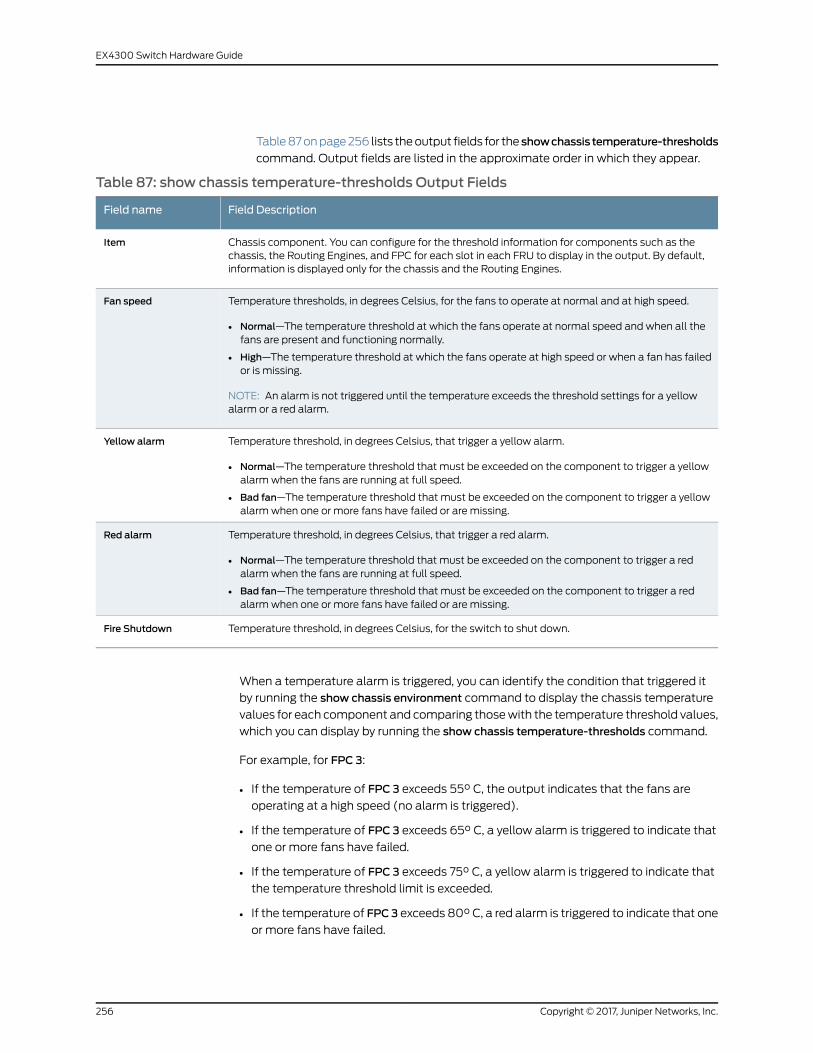
Table87onpage256 lists theoutput fields for the showchassis temperature-thresholds
command. Output fields are listed in the approximate order in which they appear.
Table 87: show chassis temperature-thresholds Output Fields
Field DescriptionField name
Chassis component. You can configure for the threshold information for components such as thechassis, the Routing Engines, and FPC for each slot in each FRU to display in the output. By default,information is displayed only for the chassis and the Routing Engines.
Item
Temperature thresholds, in degrees Celsius, for the fans to operate at normal and at high speed.
• Normal—The temperature threshold at which the fans operate at normal speed and when all thefans are present and functioning normally.
• High—The temperature threshold at which the fans operate at high speed or when a fan has failedor is missing.
NOTE: An alarm is not triggered until the temperature exceeds the threshold settings for a yellowalarm or a red alarm.
Fan speed
Temperature threshold, in degrees Celsius, that trigger a yellow alarm.
• Normal—The temperature threshold that must be exceeded on the component to trigger a yellowalarmwhen the fans are running at full speed.
• Bad fan—The temperature threshold that must be exceeded on the component to trigger a yellowalarmwhen one or more fans have failed or are missing.
Yellow alarm
Temperature threshold, in degrees Celsius, that trigger a red alarm.
• Normal—The temperature threshold that must be exceeded on the component to trigger a redalarmwhen the fans are running at full speed.
• Bad fan—The temperature threshold that must be exceeded on the component to trigger a redalarmwhen one or more fans have failed or are missing.
Red alarm
Temperature threshold, in degrees Celsius, for the switch to shut down.Fire Shutdown
When a temperature alarm is triggered, you can identify the condition that triggered it
by running the show chassis environment command to display the chassis temperature
values for each component and comparing thosewith the temperature threshold values,
which you can display by running the show chassis temperature-thresholds command.
For example, for FPC 3:
• If the temperature of FPC 3 exceeds 55° C, the output indicates that the fans are
operating at a high speed (no alarm is triggered).
• If the temperature of FPC 3 exceeds 65° C, a yellow alarm is triggered to indicate that
one or more fans have failed.
• If the temperature of FPC 3 exceeds 75° C, a yellow alarm is triggered to indicate that
the temperature threshold limit is exceeded.
• If the temperature of FPC3 exceeds 80° C, a red alarm is triggered to indicate that one
or more fans have failed.
Copyright © 2017, Juniper Networks, Inc.256
EX4300 Switch Hardware Guide

• If the temperature of FPC 3 exceeds 105° C, a red alarm is triggered to indicate that
the temperature threshold limit is exceeded.
• If the temperature of FPC 3 exceeds 110° C, the switch is powered off.
Table 88 on page 257 lists the possible causes for the switch to generate a temperature
alarm and the respective remedies.
Table 88: Causes and Remedies for Temperature Alarms
RemedyCause
Ensure that the ambient temperature is within the threshold temperaturelimit. See “Environmental Requirements and Specifications for EX SeriesSwitches” on page 88.
Ambient temperature is above thresholdtemperature.
• Check the fan.
• Replace the faulty fan module or fan tray.
• If the above two checks show no problems, open a support case using theCase Manager link at http://www.juniper.net/support/ or call1-888-314-5822 (toll-free within the United States and Canada) or1-408-745-9500 (from outside the United States).
Fanmodule or fan tray has failed.
257Copyright © 2017, Juniper Networks, Inc.
Chapter 22: Troubleshooting Switch Components
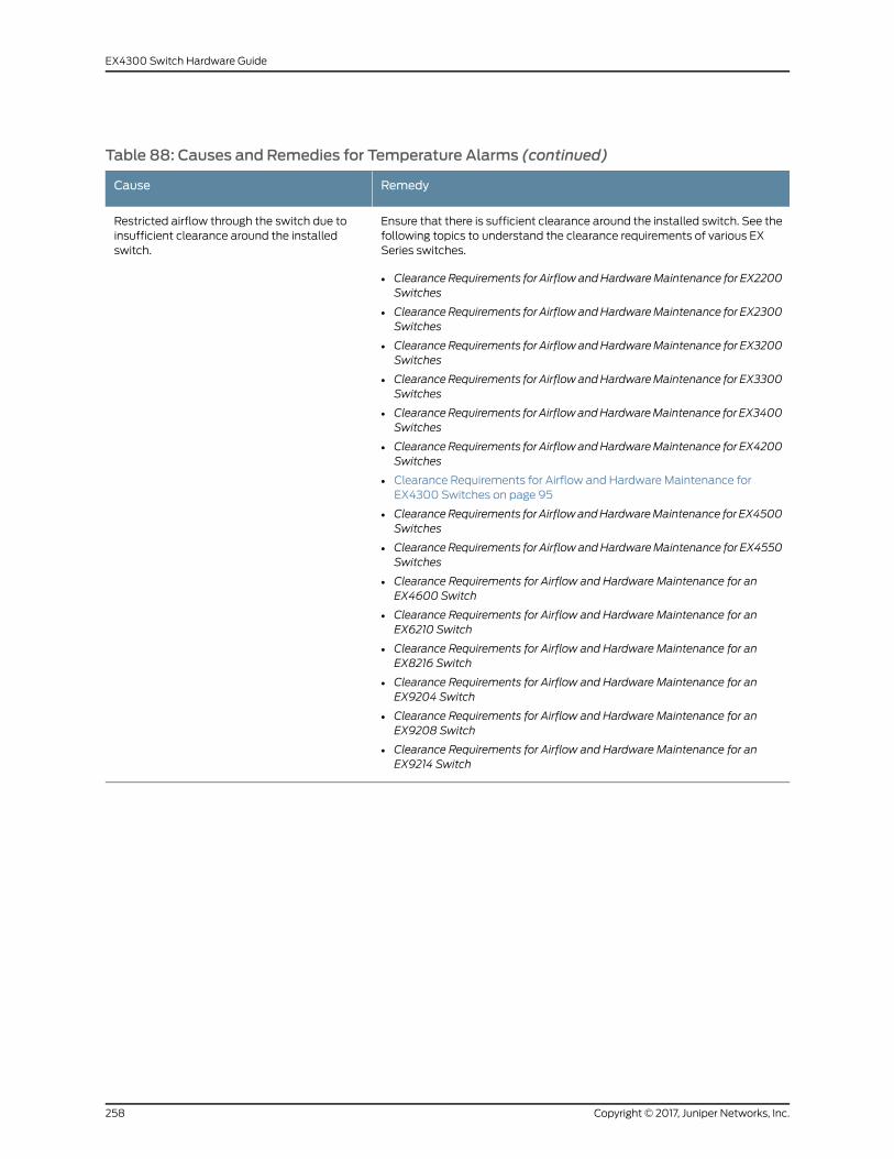
Table 88: Causes and Remedies for Temperature Alarms (continued)
RemedyCause
Ensure that there is sufficient clearance around the installed switch. See thefollowing topics to understand the clearance requirements of various EXSeries switches.
• Clearance Requirements for AirflowandHardwareMaintenance for EX2200Switches
• ClearanceRequirements for AirflowandHardwareMaintenance for EX2300Switches
• ClearanceRequirements for AirflowandHardwareMaintenance for EX3200Switches
• ClearanceRequirements for AirflowandHardwareMaintenance for EX3300Switches
• ClearanceRequirements for AirflowandHardwareMaintenance for EX3400Switches
• ClearanceRequirements for AirflowandHardwareMaintenance for EX4200Switches
• Clearance Requirements for Airflow and Hardware Maintenance forEX4300 Switches on page 95
• ClearanceRequirements for AirflowandHardwareMaintenance for EX4500Switches
• ClearanceRequirements for AirflowandHardwareMaintenance for EX4550Switches
• Clearance Requirements for Airflow and Hardware Maintenance for anEX4600 Switch
• Clearance Requirements for Airflow and Hardware Maintenance for anEX6210 Switch
• Clearance Requirements for Airflow and Hardware Maintenance for anEX8216 Switch
• Clearance Requirements for Airflow and Hardware Maintenance for anEX9204 Switch
• Clearance Requirements for Airflow and Hardware Maintenance for anEX9208 Switch
• Clearance Requirements for Airflow and Hardware Maintenance for anEX9214 Switch
Restricted airflow through the switch due toinsufficient clearance around the installedswitch.
Copyright © 2017, Juniper Networks, Inc.258
EX4300 Switch Hardware Guide

PART 6
Safety and Compliance Information
• General Safety Guidelines andWarnings on page 261
• Fire Safety Requirements on page 267
• Installation Safety Guidelines andWarnings on page 269
• Radiation and Laser Safety Guidelines andWarnings on page 279
• Maintenance and Operational SafetyWarnings on page 283
• Electrical Safety Guidelines andWarnings on page 289
• Agency Approvals and Compliance Statements on page 305
259Copyright © 2017, Juniper Networks, Inc.

Copyright © 2017, Juniper Networks, Inc.260
EX4300 Switch Hardware Guide

CHAPTER 23
General Safety Guidelines andWarnings
• General Safety Guidelines andWarnings on page 261
• Definitions of SafetyWarning Levels on page 262
• Qualified Personnel Warning on page 264
• Warning Statement for Norway and Sweden on page 265
General Safety Guidelines andWarnings
The following guidelines help ensure your safety and protect the device from damage.
The list of guidelinesmightnotaddressall potentially hazardoussituations in yourworking
environment, so be alert and exercise good judgment at all times.
• Perform only the procedures explicitly described in the hardware documentation for
this device. Make sure that only authorized service personnel perform other system
services.
• Keep the area around the device clear and free from dust before, during, and after
installation.
• Keep tools away from areas where people could trip over themwhile walking.
• Do not wear loose clothing or jewelry, such as rings, bracelets, or chains, which could
become caught in the device.
• Wear safety glasses if you are working under any conditions that could be hazardous
to your eyes.
• Do not perform any actions that create a potential hazard to people or make the
equipment unsafe.
• Never attempt to lift an object that is too heavy for one person to handle.
• Never install or manipulate wiring during electrical storms.
• Never install electrical jacks in wet locations unless the jacks are specifically designed
for wet environments.
• Operate the device only when it is properly grounded.
• Ensure that the separate protective earthing terminal provided on this device is
permanently connected to earth.
• Replace fuses only with fuses of the same type and rating.
261Copyright © 2017, Juniper Networks, Inc.

• Do not open or remove chassis covers or sheet-metal parts unless instructions are
provided in the hardware documentation for this device. Such an action could cause
severe electrical shock.
• Do not push or force any objects through any opening in the chassis frame. Such an
action could result in electrical shock or fire.
• Avoid spilling liquid onto the chassis or onto any device component. Such an action
could cause electrical shock or damage the device.
• Avoid touching uninsulated electrical wires or terminals that have not been
disconnected from their power source. Such an action could cause electrical shock.
• Always ensure that all modules, power supplies, and cover panels are fully inserted
and that the installation screws are fully tightened.
RelatedDocumentation
AC Power Electrical Safety Guidelines on page 292•
• General Electrical Safety Guidelines andWarnings on page 289
• Maintenance and Operational Safety Guidelines andWarnings on page 283
• Installation InstructionsWarning on page 269
• Grounded EquipmentWarning on page 276
Definitions of SafetyWarning Levels
The documentation uses the following levels of safety warnings (there are twoWarning
formats):
NOTE: Youmight find this information helpful in a particular situation, or youmight overlook this important information if it was not highlighted in a Note.
CAUTION: You need to observe the specified guidelines to prevent minorinjury or discomfort to you or severe damage to the device.
WARNING: This symbol alerts you to the risk of personal injury from a laser.
WARNING: This symbolmeansdanger.Youare inasituation thatcouldcausebodily injury. Before you work on any equipment, be aware of the hazardsinvolved with electrical circuitry and be familiar with standard practices forpreventing accidents.
Waarschuwing Dit waarschuwingssymbool betekent gevaar. U verkeert ineen situatie die lichamelijk letsel kan veroorzaken. Voordat u aan enige
Copyright © 2017, Juniper Networks, Inc.262
EX4300 Switch Hardware Guide

apparatuur gaat werken, dient u zich bewust te zijn van de bij elektrischeschakelingen betrokken risico's en dient u opde hoogte te zijn van standaardmaatregelen om ongelukken te voorkomen.
Varoitus Tämä varoitusmerkki merkitsee vaaraa. Olet tilanteessa, joka voijohtaa ruumiinvammaan.Ennenkuin työskenteletminkään laitteistonparissa,ota selvää sähkökytkentöihin liittyvistä vaaroista ja tavanomaisistaonnettomuuksien ehkäisykeinoista.
AttentionCe symbole d'avertissement indique un danger. Vous vous trouvezdansunesituationpouvantcauserdesblessuresoudesdommagescorporels.Avant de travailler sur un équipement, soyez conscient des dangers poséspar les circuits électriques et familiarisez-vous avec les procédurescouramment utilisées pour éviter les accidents.
Warnung DiesesWarnsymbol bedeutet Gefahr. Sie befinden sich in einerSituation, die zu einer Körperverletzung führen könnte. Bevor Sie mit derArbeit an irgendeinemGerät beginnen, seien Sie sich der mit elektrischenStromkreisen verbundenen Gefahren und der Standardpraktiken zurVermeidung von Unfällen bewußt.
AvvertenzaQuesto simbolo di avvertenza indica un pericolo. La situazionepotrebbe causare infortuni alle persone. Prima di lavorare su qualsiasiapparecchiatura, occorre conoscere i pericoli relativi ai circuiti elettrici edessere al corrente delle pratiche standard per la prevenzione di incidenti.
AdvarselDette varselsymbolet betyr fare. Du befinner deg i en situasjon somkan føre til personskade. Før du utfører arbeid på utstyr, må du vareoppmerksom på de faremomentene som elektriske kretser innebærer, samtgjøre deg kjent med vanlig praksis når det gjelder å unngå ulykker.
Aviso Este símbolo de aviso indica perigo. Encontra-se numa situação quelhepoderá causar danos físicos. Antes de começar a trabalhar comqualquerequipamento, familiarize-se com os perigos relacionados com circuitoseléctricos, e com quaisquer práticas comuns que possam prevenir possíveisacidentes.
¡Atención! Este símbolo de aviso significa peligro. Existe riesgo para suintegridad física. Antes demanipular cualquier equipo, considerar los riesgosque entraña la corriente eléctrica y familiarizarse con los procedimientosestándar de prevención de accidentes.
Varning!Denna varningssymbol signalerar fara. Du befinner dig i en situationsom kan leda till personskada. Innan du utför arbete på någon utrustningmåste du varamedveten om farornamed elkretsar och känna till vanligtförfarande för att förebygga skador.
RelatedDocumentation
General Safety Guidelines andWarnings on page 261•
263Copyright © 2017, Juniper Networks, Inc.
Chapter 23: General Safety Guidelines andWarnings

• Installation InstructionsWarning on page 269
• Maintenance and Operational Safety Guidelines andWarnings on page 283
• Grounded EquipmentWarning on page 276
• Laser and LED Safety Guidelines andWarnings on page 279
• Laser and LED Safety Guidelines andWarnings for the ACX5000 Router
• Warning Statement for Norway and Sweden on page 265
Qualified PersonnelWarning
WARNING: Only trainedandqualified personnel should install or replace thedevice.
Waarschuwing Installatie en reparaties mogen uitsluitend door getraind enbevoegd personeel uitgevoerd worden.
VaroitusAinoastaankoulutettu japätevähenkilökuntasaaasentaatai vaihtaatämän laitteen.
Attention Tout installation ou remplacement de l'appareil doit être réalisépar du personnel qualifié et compétent.
WarnungGerät nur vongeschultem, qualifiziertemPersonal installierenoderauswechseln lassen.
Avvertenza Solo personale addestrato e qualificato deve essere autorizzatoad installare o sostituire questo apparecchio.
Advarsel Kun kvalifisert personell med riktig opplæring bør montere ellerbytte ut dette utstyret.
Aviso Este equipamento deverá ser instalado ou substituído apenas porpessoal devidamente treinado e qualificado.
¡Atención! Estos equipos deben ser instalados y reemplazadosexclusivamenteporpersonal técnicoadecuadamentepreparadoycapacitado.
Varning! Denna utrustning ska endast installeras och bytas ut av utbildadoch kvalificerad personal.
RelatedDocumentation
General Safety Guidelines andWarnings on page 261•
• General Electrical Safety Guidelines andWarnings on page 289
• AC Power Electrical Safety Guidelines on page 292
• DC Power Electrical Safety Guidelines for Switches on page 294
Copyright © 2017, Juniper Networks, Inc.264
EX4300 Switch Hardware Guide

Warning Statement for Norway and Sweden
WARNING: The equipmentmust be connected to an earthedmainssocket-outlet.
Advarsel Apparatet skal kobles til en jordet stikkontakt.
Varning! Apparaten skall anslutas till jordat nätuttag.
RelatedDocumentation
• General Safety Guidelines andWarnings on page 261
265Copyright © 2017, Juniper Networks, Inc.
Chapter 23: General Safety Guidelines andWarnings

Copyright © 2017, Juniper Networks, Inc.266
EX4300 Switch Hardware Guide

CHAPTER 24
Fire Safety Requirements
• Fire Safety Requirements on page 267
Fire Safety Requirements
In the event of a fire emergency, the safety of people is the primary concern. You should
establishprocedures for protectingpeople in theeventof a fire emergency, provide safety
training, and properly provision fire-control equipment and fire extinguishers.
In addition, you should establish procedures to protect your equipment in the event of a
fire emergency. JuniperNetworksproducts shouldbe installed inanenvironment suitable
for electronic equipment. We recommend that fire suppression equipment be available
in the event of a fire in the vicinity of the equipment and that all local fire, safety, and
electrical codesandordinancesbeobservedwhenyou install andoperateyourequipment.
Fire Suppression
In the event of an electrical hazard or an electrical fire, you should first turn power off to
theequipmentat the source. ThenuseaTypeC fire extinguisher,whichusesnoncorrosive
fire retardants, to extinguish the fire.
Fire Suppression Equipment
Type C fire extinguishers, which use noncorrosive fire retardants such as carbon dioxide
andHalotron™,aremosteffective for suppressingelectrical fires. TypeC fire extinguishers
displace oxygen from the point of combustion to eliminate the fire. For extinguishing fire
on or around equipment that draws air from the environment for cooling, you should use
this type of inert oxygen displacement extinguisher instead of an extinguisher that leaves
residues on equipment.
Do not use multipurpose Type ABC chemical fire extinguishers (dry chemical fire
extinguishers). The primary ingredient in these fire extinguishers is monoammonium
phosphate,which is very sticky anddifficult to clean. In addition, in thepresenceofminute
amounts of moisture, monoammonium phosphate can become highly corrosive and
corrodes most metals.
Any equipment in a room in which a chemical fire extinguisher has been discharged is
subject to premature failure and unreliable operation. The equipment is considered to
be irreparably damaged.
267Copyright © 2017, Juniper Networks, Inc.

NOTE: Tokeepwarrantieseffective,donotuseadrychemical fireextinguisherto control a fire at or near a Juniper Networks device. If a dry chemical fireextinguisher is used, the unit is no longer eligible for coverage under a serviceagreement.
We recommend that you dispose of any irreparably damaged equipment in an
environmentally responsible manner.
RelatedDocumentation
• General Safety Guidelines andWarnings on page 261
• General Electrical Safety Guidelines andWarnings on page 289
• Action to Take After an Electrical Accident on page 290
Copyright © 2017, Juniper Networks, Inc.268
EX4300 Switch Hardware Guide

CHAPTER 25
Installation Safety Guidelines andWarnings
• Installation InstructionsWarning on page 269
• Chassis Lifting Guidelines on page 270
• Restricted AccessWarning on page 270
• RampWarning on page 272
• Rack-Mounting and Cabinet-MountingWarnings on page 272
• Wall-MountingWarning for EX4300 Switches on page 276
• Grounded EquipmentWarning on page 276
Installation InstructionsWarning
WARNING: Read the installation instructions before you connect the deviceto a power source.
WaarschuwingRaadpleegde installatie-aanwijzingenvoordatuhetsysteemmet de voeding verbindt.
VaroitusLueasennusohjeetennen järjestelmänyhdistämistävirtalähteeseen.
AttentionAvantdebrancher lesystèmesur lasourced'alimentation,consulterles directives d'installation.
Warnung Lesen Sie die Installationsanweisungen, bevor Sie das System andie Stromquelle anschließen.
AvvertenzaConsultare le istruzionidi installazioneprimadicollegare il sistemaall'alimentatore.
Advarsel Les installasjonsinstruksjonene før systemet kobles til strømkilden.
Aviso Leia as instruções de instalação antes de ligar o sistema à sua fontede energia.
¡Atención! Ver las instrucciones de instalación antes de conectar el sistemaa la red de alimentación.
269Copyright © 2017, Juniper Networks, Inc.

Varning! Läs installationsanvisningarna innan du kopplar systemet till dessströmförsörjningsenhet.
RelatedDocumentation
General Safety Guidelines andWarnings on page 261•
• Laser and LED Safety Guidelines andWarnings on page 279
• Laser and LED Safety Guidelines andWarnings for the ACX5000 Router
• Grounded EquipmentWarning on page 276
Chassis Lifting Guidelines
• Beforemoving thedevice toa site, ensure that the sitemeets thepower, environmental,
and clearance requirements.
• Before lifting or moving the device, disconnect all external cables and wires.
• As when lifting any heavy object, ensure that most of the weight is borne by your legs
rather than your back. Keep your knees bent and your back relatively straight. Do not
twist your body as you lift. Balance the load evenly andbe sure that your footing is firm.
• Use the following lifting guidelines to lift routing devices and components:
• Up to 39.7 lb (18 kg): One person.
• 39.7 lb (18 kg) to 70.5 lb (32 kg): Two or more people.
• 70.5 lb (32 kg) to 121.2 lb (55 kg): Three or more people.
• Above 121.2 lbs (55 kg): Material handling systems (such as levers, slings, lifts and
so on)must be used.When this is not practical, specially trained persons or systems
must be used (riggers or movers).
RelatedDocumentation
General Safety Guidelines andWarnings on page 261•
• Installation InstructionsWarning on page 269
Restricted AccessWarning
WARNING: This unit is intended for installation in restricted access areas. Arestrictedaccessarea isanarea towhichaccesscanbegainedonlybyservicepersonnel through the use of a special tool, lock and key, or other means ofsecurity, andwhich is controlled by the authority responsible for the location.
WaarschuwingDit toestel isbedoeldvoor installatieopplaatsenmetbeperktetoegang.Eenplaatsmetbeperkte toegang iseenplaatswaar toegangslechtsdoor servicepersoneel verkregen kan worden door middel van een speciaalinstrument, een slot en sleutel, of een ander veiligheidsmiddel, en welke
Copyright © 2017, Juniper Networks, Inc.270
EX4300 Switch Hardware Guide

beheerd wordt door de overheidsinstantie die verantwoordelijk is voor delocatie.
Varoitus Tämä laite on tarkoitettu asennettavaksi paikkaan, johon pääsy onrajoitettua. Paikka, johon pääsy on rajoitettua, tarkoittaa paikkaa, johon vainhuoltohenkilöstö pääsee jonkin erikoistyökalun, lukkoon sopivan avaimentai jonkin muun turvalaitteen avulla ja joka on paikasta vastuussa olevientoimivaltaisten henkilöiden valvoma.
Attention Cet appareil est à installer dans des zones d'accès réservé. Cesdernières sontdeszonesauxquelles seul lepersonneldeservicepeutaccéderen utilisant un outil spécial, unmécanisme de verrouillage et une clé, ou toutautre moyen de sécurité. L'accès aux zones de sécurité est sous le contrôlede l'autorité responsable de l'emplacement.
Warnung Diese Einheit ist zur Installation in Bereichenmit beschränktemZutritt vorgesehen. Ein Bereichmit beschränktem Zutritt ist ein Bereich, zudem nurWartungspersonal mit einem Spezialwerkzeugs, Schloß undSchlüssel oder anderer Sicherheitsvorkehrungen Zugang hat, und der vondem für die Anlage zuständigen Gremium kontrolliert wird.
AvvertenzaQuestaunitàdeveessere installata inun'areaadaccesso limitato.Un'area ad accesso limitato è un'area accessibile solo a personale diassistenza tramite un'attrezzo speciale, lucchetto, o altri dispositivi disicurezza, ed è controllata dall'autorità responsabile della zona.
Advarsel Denne enheten er laget for installasjon i områder med begrensetadgang.Etområdemedbegrensetadganggir kunadgangtil servicepersonalesom bruker et spesielt verktøy, lås og nøkkel, eller en annensikkerhetsanordning, og det kontrolleres av den autoriteten som er ansvarligfor området.
AvisoEstaunidade foi concebidapara instalaçãoemáreasdeacesso restrito.Uma área de acesso restrito é uma área à qual apenas temacesso o pessoalde serviço autorizado, que possua uma ferramenta, chave e fechaduraespecial, ou qualquer outra forma de segurança. Esta área é controlada pelaautoridade responsável pelo local.
¡Atención! Esta unidad ha sido diseñada para instalarse en áreas de accesorestringido. Área de acceso restringido significa un área a la que solamentetieneaccesoelpersonaldeserviciomediante lautilizacióndeunaherramientaespecial, cerradura con llave, o algún otromedio de seguridad, y que estábajo el control de la autoridad responsable del local.
Varning! Denna enhet är avsedd för installation i områdenmed begränsattillträde. Ett områdemed begränsat tillträde får endast tillträdas avservicepersonal med ett speciellt verktyg, lås och nyckel, eller annansäkerhetsanordning, och kontrolleras av den auktoritet som ansvarar förområdet.
271Copyright © 2017, Juniper Networks, Inc.
Chapter 25: Installation Safety Guidelines andWarnings
RelatedDocumentation
General Safety Guidelines andWarnings on page 261•
• General Electrical Safety Guidelines andWarnings on page 289
• Installation InstructionsWarning on page 269
• Grounded EquipmentWarning on page 276
RampWarning
WARNING: When installing the device, do not use a ramp inclined at morethan 10 degrees.
WaarschuwingGebruik een oprijplaat niet onder een hoek vanmeer dan 10graden.
VaroitusÄläkäytäsellaistakaltevaapintaa, jonkakaltevuusylittää 10astetta.
AttentionNe pas utiliser une rampe dont l'inclinaison est supérieure à 10degrés.
WarnungKeine Rampenmit einer Neigung vonmehr als 10 Grad verwenden.
AvvertenzaNon usare una rampa con pendenza superiore a 10 gradi.
Advarsel Bruk aldri en rampe som heller mer enn 10 grader.
AvisoNão utilize uma rampa com uma inclinação superior a 10 graus.
¡Atención!No usar una rampa inclinadamás de 10 grados
Varning! Använd inte rampmed en lutning påmer än 10 grader.
RelatedDocumentation
General Safety Guidelines andWarnings on page 261•
• Installation InstructionsWarning on page 269
• Grounded EquipmentWarning on page 276
Rack-Mounting and Cabinet-MountingWarnings
Ensure that the rack or cabinet in which the device is installed is evenly and securely
supported. Unevenmechanical loading could lead to a hazardous condition.
WARNING: To prevent bodily injury whenmounting or servicing the devicein a rack, take the following precautions to ensure that the system remainsstable. The following directives helpmaintain your safety:
Copyright © 2017, Juniper Networks, Inc.272
EX4300 Switch Hardware Guide

• The devicemust be installed in a rack that is secured to the buildingstructure.
• Thedevice should bemountedat thebottomof the rack if it is the only unitin the rack.
• Whenmounting the device on a partially filled rack, load the rack from thebottom to the topwith the heaviest component at the bottom of the rack.
• If the rack is provided with stabilizing equipment, install the stabilizersbeforemounting or servicing the device in the rack.
WaarschuwingOm lichamelijk letsel te voorkomenwanneer u dit toestel ineen rekmonteert of het daar een servicebeurt geeft, moet u specialevoorzorgsmaatregelen nemen om ervoor te zorgen dat het toestel stabielblijft. De onderstaande richtlijnen worden verstrekt om uw veiligheid teverzekeren:
• De Juniper Networks switchmoet in een stellage worden geïnstalleerd dieaan een bouwsel is verankerd.
• Dit toestel dient onderaan in het rek gemonteerd teworden als het toestelhet enige in het rek is.
• Wanneer u dit toestel in een gedeeltelijk gevuld rekmonteert, dient u hetrekvanonderennaarboven te ladenmethet zwaarsteonderdeelonderaanin het rek.
• Als het rek voorzien is van stabiliseringshulpmiddelen, dient u destabilisatoren temonteren voordat u het toestel in het rekmonteert of hetdaar een servicebeurt geeft.
VaroitusKun laiteasetetaan telineeseen taihuolletaansenollessa telineessä,onnoudatettavaerityisiävarotoimia järjestelmänvakavuudensäilyttämiseksi,jotta vältytään loukkaantumiselta. Noudata seuraavia turvallisuusohjeita:
• Juniper Networks switch on asennettava telineeseen, joka on kiinnitettyrakennukseen.
• Jos telineessä ei ole muita laitteita, aseta laite telineen alaosaan.
• Jos laite asetetaan osaksi täytettyyn telineeseen, aloita kuormittaminensen alaosasta kaikkein raskaimmalla esineellä ja siirry sitten sen yläosaan.
• Jos telinettä varten on vakaimet, asenna ne ennen laitteen asettamistatelineeseen tai sen huoltamista siinä.
Attention Pour éviter toute blessure corporelle pendant les opérations demontage ou de réparation de cette unité en casier, il convient de prendre desprécautions spécialesafindemaintenir la stabilité du système. Lesdirectivesci-dessous sont destinées à assurer la protection du personnel:
273Copyright © 2017, Juniper Networks, Inc.
Chapter 25: Installation Safety Guidelines andWarnings

• Le rack sur lequel est monté le Juniper Networks switch doit être fixé à lastructure du bâtiment.
• Si cette unité constitue la seule unitémontéeencasier, elle doit êtreplacéedans le bas.
• Si cette unité est montée dans un casier partiellement rempli, charger lecasier de bas en haut en plaçant l'élément le plus lourd dans le bas.
• Si lecasier estéquipédedispositifs stabilisateurs, installer les stabilisateursavant demonter ou de réparer l'unité en casier.
WarnungZurVermeidungvonKörperverletzungbeimAnbringenoderWartendieser Einheit in einemGestell müssen Sie besondere Vorkehrungen treffen,um sicherzustellen, daß das System stabil bleibt. Die folgenden Richtliniensollen zur Gewährleistung Ihrer Sicherheit dienen:
• Der Juniper Networks switchmuß in einemGestell installiert werden, dasin der Gebäudestruktur verankert ist.
• Wenn diese Einheit die einzige im Gestell ist, sollte sie unten im Gestellangebracht werden.
• Bei Anbringung dieser Einheit in einem zum Teil gefüllten Gestell ist dasGestell von unten nach oben zu laden, wobei das schwerste Bauteil untenim Gestell anzubringen ist.
• Wird das Gestell mit Stabilisierungszubehör geliefert, sind zuerst dieStabilisatoren zu installieren, bevor Sie die Einheit im Gestell anbringenoder sie warten.
AvvertenzaPerevitare infortuni fisici durante ilmontaggioo lamanutenzionedi questa unità in un supporto, occorre osservare speciali precauzioni pergarantire che il sistema rimanga stabile. Le seguenti direttive vengono forniteper garantire la sicurezza personale:
• Il Juniper Networks switch deve essere installato in un telaio, il quale deveessere fissato alla struttura dell'edificio.
• Questa unità deve venire montata sul fondo del supporto, se si trattadell'unica unità damontare nel supporto.
• Quando questa unità vienemontata in un supporto parzialmente pieno,caricare il supporto dal basso all'alto, con il componente più pesantesistemato sul fondo del supporto.
• Se il supporto è dotato di dispositivi stabilizzanti, installare tali dispositiviprimadimontareodiprocedereallamanutenzionedell'unitànel supporto.
AdvarselUnngå fysiske skader under montering eller reparasjonsarbeid pådenne enheten når den befinner seg i et kabinett. Vær nøyemed at systemeter stabilt. Følgende retningslinjer er gitt for å verne om sikkerheten:
Copyright © 2017, Juniper Networks, Inc.274
EX4300 Switch Hardware Guide
• Juniper Networks switchmå installeres i et stativ som er forankret tilbygningsstrukturen.
• Denne enheten børmonteres nederst i kabinettet hvis dette er den enesteenheten i kabinettet.
• Vedmontering av denne enheten i et kabinett som er delvis fylt, skalkabinettet lastes frabunnenogoppmeddentyngstekomponentennedersti kabinettet.
• Hvis kabinettet er utstyrt med stabiliseringsutstyr, skal stabilisatoreneinstalleres før montering eller utføring av reparasjonsarbeid på enheten ikabinettet.
Aviso Para se prevenir contra danos corporais aomontar ou reparar estaunidade numaestante, deverá tomar precauções especiais para se certificarde que o sistema possui um suporte estável. As seguintes directrizesajudá-lo-ão a efectuar o seu trabalho com segurança:
• O Juniper Networks switch deverá ser instalado numa prateleira fixa àestrutura do edificio.
• Esta unidade deverá ser montada na parte inferior da estante, caso sejaesta a única unidade a ser montada.
• Aomontar esta unidade numa estante parcialmente ocupada, coloque ositensmais pesados na parte inferior da estante, arrumando-os de baixopara cima.
• Se a estante possuir um dispositivo de estabilização, instale-o antes demontar ou reparar a unidade.
¡Atención! Para evitar lesiones durante el montaje de este equipo sobre unbastidor, o posteriormente durante sumantenimiento, se debeponermuchocuidado en que el sistema quede bien estable. Para garantizar su seguridad,proceda según las siguientes instrucciones:
• El Juniper Networks switch debe instalarse en un bastidor fijado a laestructura del edificio.
• Colocar el equipo en la parte inferior del bastidor, cuando sea la únicaunidad en el mismo.
• Cuandoesteequiposevayaa instalarenunbastidorparcialmenteocupado,comenzar la instalación desde la parte inferior hacia la superior colocandoel equipomás pesado en la parte inferior.
• Si el bastidor dispone de dispositivos estabilizadores, instalar éstos antesdemontaroprocederalmantenimientodel equipo instaladoenelbastidor.
Varning! För att undvika kroppsskada när du installerar eller utförunderhållsarbete på denna enhet på en ställningmåste du vidta särskilda
275Copyright © 2017, Juniper Networks, Inc.
Chapter 25: Installation Safety Guidelines andWarnings
försiktighetsåtgärder föratt försäkradigomattsystemetstår stadigt. Följanderiktlinjer ges för att trygga din säkerhet:
• Juniper Networks switchmåste installeras i en ställning som är förankradi byggnadens struktur.
• Omdenna enhet är den enda enheten på ställningen skall den installeraslängst ned på ställningen.
• Omdenna enhet installeras på en delvis fylld ställning skall ställningenfyllasnedifrånochupp,meddetyngstaenheterna längstnedpåställningen.
• Omställningenär förseddmedstabiliseringsdonskalldessamonteras fastinnan enheten installeras eller underhålls på ställningen.
RelatedDocumentation
General Safety Guidelines andWarnings on page 261•
• Installation InstructionsWarning on page 269
• Grounded EquipmentWarning on page 276
Wall-MountingWarning for EX4300 Switches
WARNING: Whenmounting an EX4300 switch chassis in a vertical position,orient the front panel of the chassis downward to ensure proper airflow andmeet safety requirements in the event of a fire.
RelatedDocumentation
Mounting an EX4300 Switch on aWall on page 145•
Grounded EquipmentWarning
WARNING: Thedevice is intended tobegrounded.Duringnormaluse, ensurethat you have connected earth ground to the chassis.
Waarschuwing Deze apparatuur hoort geaard te worden Zorg dat dehost-computer tijdens normaal gebruik met aarde is verbonden.
Varoitus Tämä laitteisto on tarkoitettumaadoitettavaksi. Varmista, ettäisäntälaite on yhdistetty maahan normaalikäytön aikana.
Attention Cet équipement doit être relié à la terre. S'assurer que l'appareilhôte est relié à la terre lors de l'utilisation normale.
Warnung Dieses Gerät muß geerdet werden. Stellen Sie sicher, daß dasHost-Gerät während des normalen Betriebs an Erde gelegt ist.
Copyright © 2017, Juniper Networks, Inc.276
EX4300 Switch Hardware Guide

AvvertenzaQuestaapparecchiaturadeveesserecollegataamassa.Accertarsiche il dispositivo host sia collegato alla massa di terra durante il normaleutilizzo.
AdvarselDette utstyret skal jordes. Forviss deg om vertsterminalen er jordetved normalt bruk.
Aviso Este equipamento deverá estar ligado à terra. Certifique-se que o hostse encontra ligado à terra durante a sua utilização normal.
¡Atención!Esteequipodebeconectarsea tierra.Asegurarsedequeel equipoprincipal esté conectado a tierra durante el uso normal.
Varning! Denna utrustning är avsedd att jordas. Se till att värdenheten ärjordad vid normal användning.
RelatedDocumentation
• General Safety Guidelines andWarnings on page 261
• AC Power Electrical Safety Guidelines on page 292
• DC Power Electrical Safety Guidelines for Switches on page 294
277Copyright © 2017, Juniper Networks, Inc.
Chapter 25: Installation Safety Guidelines andWarnings

Copyright © 2017, Juniper Networks, Inc.278
EX4300 Switch Hardware Guide

CHAPTER 26
RadiationandLaserSafetyGuidelinesandWarnings
• Laser and LED Safety Guidelines andWarnings on page 279
• Radiation fromOpen Port AperturesWarning on page 281
Laser and LED Safety Guidelines andWarnings
Juniper Networks devices are equipped with laser transmitters, which are considered a
Class 1 Laser Product by the U.S. Food and Drug Administration and are evaluated as a
Class 1 Laser Product per EN 60825-1 requirements.
Observe the following guidelines and warnings:
• General Laser Safety Guidelines on page 279
• Class 1 Laser ProductWarning on page 280
• Class 1 LED ProductWarning on page 280
• Laser BeamWarning on page 280
General Laser Safety Guidelines
When working around ports that support optical transceivers, observe the following
safety guidelines to prevent eye injury:
• Do not look into unterminated ports or at fibers that connect to unknown sources.
• Do not examine unterminated optical ports with optical instruments.
• Avoid direct exposure to the beam.
WARNING: Unterminated optical connectors can emit invisible laserradiation. The lens in the human eye focuses all the laser power on theretina, so focusing the eye directly on a laser source—even a low-powerlaser—could permanently damage the eye.
279Copyright © 2017, Juniper Networks, Inc.
Class 1 Laser ProductWarning
WARNING: Class 1 laser product.
Waarschuwing Klasse-1 laser produkt.
Varoitus Luokan 1 lasertuote.
Attention Produit laser de classe I.
Warnung Laserprodukt der Klasse 1.
Avvertenza Prodotto laser di Classe 1.
Advarsel Laserprodukt av klasse 1.
Aviso Produto laser de classe 1.
¡Atención! Producto láser Clase I.
Varning! Laserprodukt av klass 1.
Class 1 LED ProductWarning
WARNING: Class 1 LED product.
Waarschuwing Klasse 1 LED-product.
Varoitus Luokan 1 valodiodituote.
Attention Alarme de produit LED Class I.
Warnung Class 1 LED-Produktwarnung.
Avvertenza Avvertenza prodotto LED di Classe 1.
Advarsel LED-produkt i klasse 1.
Aviso Produto de classe 1 com LED.
¡Atención! Aviso sobre producto LED de Clase 1.
Varning! Lysdiodprodukt av klass 1.
Laser BeamWarning
WARNING: Do not stare into the laser beam or view it directly with opticalinstruments.
Copyright © 2017, Juniper Networks, Inc.280
EX4300 Switch Hardware Guide
WaarschuwingNiet in de straal staren of hem rechtstreeks bekijkenmetoptische instrumenten.
Varoitus Älä katso säteeseen äläkä tarkastele sitä suoraan optisen laitteenavulla.
AttentionNe pas fixer le faisceau des yeux, ni l'observer directement à l'aided'instruments optiques.
WarnungNicht direkt in den Strahl blicken und ihn nicht direktmit optischenGeräten prüfen.
AvvertenzaNon fissare il raggio con gli occhi né usare strumenti ottici perosservarlo direttamente.
Advarsel Stirr eller se ikke direkte p strlenmed optiske instrumenter.
AvisoNão olhe fixamente para o raio, nem olhe para ele directamente cominstrumentos ópticos.
¡Atención!Nomirar fijamente el haz ni observarlo directamente coninstrumentos ópticos.
Varning! Rikta inte blicken in mot strålen och titta inte direkt på den genomoptiska instrument.
RelatedDocumentation
General Safety Guidelines andWarnings on page 261•
• Radiation fromOpen Port AperturesWarning on page 281
• Installation InstructionsWarning on page 269
• Grounded EquipmentWarning on page 276
Radiation fromOpen Port AperturesWarning
WARNING: Because invisible radiationmight be emitted from the apertureof the portwhen no fiber cable is connected, avoid exposure to radiation anddo not stare into open apertures.
Waarschuwing Aangezien onzichtbare straling vanuit de opening van depoort kan komen als er geen fiberkabel aangesloten is, dient blootstellingaan straling en het kijken in open openingen vermeden te worden.
Varoitus Koska portin aukosta voi emittoitua näkymätöntä säteilyä, kunkuitukaapelia ei ole kytkettynä, vältä säteilylle altistumista äläkä katsoavoimiin aukkoihin.
281Copyright © 2017, Juniper Networks, Inc.
Chapter 26: Radiation and Laser Safety Guidelines andWarnings
Attention Des radiations invisibles à l'il nu pouvant traverser l'ouverture duport lorsqu'aucun câble en fibre optique n'y est connecté, il est recommandéde ne pas regarder fixement l'intérieur de ces ouvertures.
Warnung Aus der Port-Öffnung können unsichtbare Strahlen emittieren,wenn kein Glasfaserkabel angeschlossen ist. Vermeiden Sie es, sich denStrahlungen auszusetzen, und starren Sie nicht in die Öffnungen!
AvvertenzaQuando i cavi in fibranonsono inseriti, radiazioni invisibili possonoessere emesse attraverso l'apertura della porta. Evitate di esporvi alleradiazioni e non guardate direttamente nelle aperture.
AdvarselUnngåutsettelse for stråling, ogstirr ikke inn i åpninger someråpne,fordi usynlig stråling kan emiteres fra portens åpning når det ikke er tilkobleten fiberkabel.
AvisoDadaapossibilidadedeemissãode radiação invisível atravésdoorifícioda via de acesso, quando esta não tiver nenhum cabo de fibra conectado,deverá evitar a exposição à radiação e não deverá olhar fixamente paraorifícios que se encontrarem a descoberto.
¡Atención!Debidoaque laaperturadelpuertopuedeemitir radiación invisiblecuando no existe un cable de fibra conectado, evitemirar directamente a lasaperturas para no exponerse a la radiación.
Varning!Osynlig strålning kan avges från en portöppning utan anslutenfiberkabel ochdubör därför undvika att bli utsatt för strålning genomatt intestirra in i oskyddade öppningar.
RelatedDocumentation
• General Safety Guidelines andWarnings on page 261
• Laser and LED Safety Guidelines andWarnings on page 279
• Laser and LED Safety Guidelines andWarnings for the ACX5000 Router
• Installation InstructionsWarning on page 269
• Grounded EquipmentWarning on page 276
Copyright © 2017, Juniper Networks, Inc.282
EX4300 Switch Hardware Guide

CHAPTER 27
Maintenance and Operational SafetyWarnings
• Maintenance and Operational Safety Guidelines andWarnings on page 283
Maintenance and Operational Safety Guidelines andWarnings
Whileperforming themaintenanceactivities fordevices, observe the followingguidelines
and warnings:
• Battery HandlingWarning on page 283
• Jewelry Removal Warning on page 284
• Lightning Activity Warning on page 285
• Operating TemperatureWarning on page 286
• Product Disposal Warning on page 287
Battery HandlingWarning
WARNING: Replacing a battery incorrectly might result in an explosion.Replace a battery only with the same or equivalent type recommended bythemanufacturer. Disposeof usedbatteries according to themanufacturer'sinstructions.
Waarschuwing Er is ontploffingsgevaar als de batterij verkeerd vervangenwordt. Vervang de batterij slechts met hetzelfde of een equivalent type datdoor de fabrikant aanbevolen is. Gebruikte batterijendienenovereenkomstigfabrieksvoorschriften weggeworpen te worden.
Varoitus Räjähdyksen vaara, jos akku on vaihdettu väärään akkuun. Käytävaihtamiseen ainoastaan saman- tai vastaavantyyppistä akkua, joka onvalmistajansuosittelema.Hävitäkäytetytakutvalmistajanohjeidenmukaan.
Attention Danger d'explosion si la pile n'est pas remplacée correctement.Ne la remplacer que par une pile de type semblable ou équivalent,recommandée par le fabricant. Jeter les piles usagées conformément auxinstructions du fabricant.
283Copyright © 2017, Juniper Networks, Inc.
Warnung Bei Einsetzen einer falschen Batterie besteht Explosionsgefahr.Ersetzen Sie die Batterie nur durch den gleichen oder vomHerstellerempfohlenen Batterietyp. Entsorgen Sie die benutzten Batterien nach denAnweisungen des Herstellers.
Advarsel Det kan være fare for eksplosjon hvis batteriet skiftes på feil måte.Skift kunmed sammeeller tilsvarende type somer anbefalt av produsenten.Kasser brukte batterier i henhold til produsentens instruksjoner.
Avvertenza Pericolo di esplosione se la batteria non è installatacorrettamente.Sostituiresoloconunadi tipougualeoequivalente, consigliatadalproduttore. Eliminare lebatterieusatesecondo le istruzionidelproduttore.
AvisoExiste perigo de explosão se a bateria for substituída incorrectamente.Substitua a bateria por uma bateria igual ou de um tipo equivalenterecomendado pelo fabricante. Destrua as baterias usadas conforme asinstruções do fabricante.
¡Atención! Existe peligro de explosión si la batería se reemplaza demaneraincorrecta. Reemplazar la batería exclusivamente con el mismo tipo o elequivalente recomendado por el fabricante. Desechar las baterías gastadassegún las instrucciones del fabricante.
Varning!Explosionsfara vid felaktigt batteribyte. Ersätt endast batterietmedsamma batterityp som rekommenderas av tillverkaren eller motsvarande.Följ tillverkarens anvisningar vid kassering av använda batterier.
Jewelry RemovalWarning
WARNING: Before working on equipment that is connected to power lines,remove jewelry, including rings, necklaces, and watches. Metal objects heatupwhen connected to power and ground and can cause serious burns or canbe welded to the terminals.
Waarschuwing Alvorens aan apparatuur te werken die met elektrischeleidingen is verbonden, sieraden (inclusief ringen, kettingen en horloges)verwijderen. Metalen voorwerpen worden warmwanneer zemet stroom enaarde zijn verbonden, en kunnen ernstige brandwonden veroorzaken of hetmetalen voorwerp aan de aansluitklemmen lassen.
Varoitus Ennen kuin työskentelet voimavirtajohtoihin kytkettyjen laitteidenparissa, otapois kaikki korut (sormukset, kaulakorut ja kellotmukaan lukien).Metalliesineet kuumenevat, kun ne ovat yhteydessä sähkövirran ja maankanssa, janevoivataiheuttaavakaviapalovammoja tai hitsatametalliesineetkiinni liitäntänapoihin.
AttentionAvantd'accéderàcetéquipementconnectéaux lignesélectriques,ôter toutbijou(anneaux,colliersetmontrescompris). Lorsqu'ilssontbranchés
Copyright © 2017, Juniper Networks, Inc.284
EX4300 Switch Hardware Guide

à l'alimentation et reliés à la terre, les objets métalliques chauffent, ce quipeutprovoquerdesblessuresgravesousouder l'objetmétalliqueauxbornes.
Warnung Vor der Arbeit an Geräten, die an das Netz angeschlossen sind,jeglichen Schmuck (einschließlich Ringe, Ketten und Uhren) abnehmen.Metallgegenstände erhitzen sich, wenn sie an das Netz und die Erdeangeschlossen werden, und können schwere Verbrennungen verursachenoder an die Anschlußklemmen angeschweißt werden.
Avvertenza Prima di intervenire su apparecchiature collegate alle linee dialimentazione, togliersi qualsiasi monile (inclusi anelli, collane, braccialettied orologi). Gli oggetti metallici si riscaldano quando sono collegati tra puntidi alimentazione emassa: possono causare ustioni gravi oppure il metallopuò saldarsi ai terminali.
Advarsel Fjern alle smykker (inkludert ringer, halskjeder og klokker) før duskal arbeidepåutstyr somer koblet til kraftledninger.Metallgjenstander somer koblet til kraftledninger og jord blir svært varme og kan forårsake alvorligebrannskader eller smelte fast til polene.
Aviso Antes de trabalhar em equipamento que esteja ligado a linhas decorrente, retire todas as jóias que estiver a usar (incluindo anéis, fios erelógios). Os objectosmetálicos aquecerão em contacto com a corrente eem contacto com a ligação à terra, podendo causar queimaduras graves ouficarem soldados aos terminais.
¡Atención! Antes de operar sobre equipos conectados a líneas dealimentación, quitarse las joyas (incluidos anillos, collares y relojes). Losobjetosdemetal secalientancuandoseconectana laalimentaciónyatierra,lo que puede ocasionar quemaduras graves o que los objetosmetálicosqueden soldados a los bornes.
Varning! Tag av alla smycken (inklusive ringar, halsband och armbandsur)innanduarbetarpåutrustningsomärkopplad till kraftledningar.Metallobjekthettas upp när de kopplas ihopmed ström och jord och kan förorsakaallvarliga brännskador; metallobjekt kan också sammansvetsasmedkontakterna.
Lightning ActivityWarning
WARNING: Donotworkon thesystemorconnectordisconnectcablesduringperiods of lightning activity.
Waarschuwing Tijdens onweer dat gepaard gaat met bliksem, dient u nietaan het systeem te werken of kabels aan te sluiten of te ontkoppelen.
Varoitus Älä työskentele järjestelmän parissa äläkä yhdistä tai irrotakaapeleita ukkosilmalla.
285Copyright © 2017, Juniper Networks, Inc.
Chapter 27: Maintenance and Operational SafetyWarnings
AttentionNe pas travailler sur le système ni brancher ou débrancher lescâbles pendant un orage.
Warnung Arbeiten Sie nicht am System und schließen Sie keine Kabel anbzw. trennen Sie keine ab, wenn es gewittert.
AvvertenzaNon lavorare sul sistema o collegare oppure scollegare i cavidurante un temporale con fulmini.
AdvarselUtfør aldri arbeidpåsystemet, eller koble kabler til eller fra systemetnår det tordner eller lyner.
AvisoNão trabalhe no sistema ou ligue e desligue cabos durante períodosdemau tempo (trovoada).
¡Atención!No operar el sistema ni conectar o desconectar cables durante eltranscurso de descargas eléctricas en la atmósfera.
Varning!Vid åska skall du aldrig utföra arbete på systemet eller ansluta ellerkoppla loss kablar.
Operating TemperatureWarning
WARNING: To prevent the device from overheating, do not operate it in anarea that exceeds themaximum recommended ambient temperature. Toprevent airflow restriction, allow at least 6 in. (15.2 cm) of clearance aroundthe ventilation openings.
WaarschuwingOm te voorkomen dat welke switch van de Juniper Networksrouter dan ook oververhit raakt, dient u deze niet te bedienen op een plaatswaar demaximale aanbevolen omgevingstemperatuur van 40° Cwordtoverschreden. Om te voorkomen dat de luchtstroomwordt beperkt, dient erminstens 15,2 cm speling rond de ventilatie-openingen te zijn.
Varoitus Ettei Juniper Networks switch-sarjan reititin ylikuumentuisi, sitä eisaa käyttää tilassa, jonka lämpötila ylittää korkeimman suositellunympäristölämpötilan 40° C. Ettei ilmanvaihto estyisi, tuuletusaukkojenympärille on jätettävä ainakin 15,2 cm tilaa.
Attention Pour éviter toute surchauffe des routeurs de la gamme JuniperNetworks switch, ne l'utilisez pas dans une zoneoù la température ambianteest supérieure à 40° C. Pour permettre un flot d'air constant, dégagez unespace d'aumoins 15,2 cm autour des ouvertures de ventilations.
WarnungUmeinenRouterder switchvorÜberhitzungzuschützen,darfdiesernicht in einer Gegend betrieben werden, in der die Umgebungstemperaturdas empfohlene Maximum von 40° C überschreitet. Um Lüftungsverschlußzu verhindern, achten Sie darauf, daßmindestens 15,2 cm lichter Raum umdie Lüftungsöffnungen herum frei bleibt.
Copyright © 2017, Juniper Networks, Inc.286
EX4300 Switch Hardware Guide

Avvertenza Per evitare il surriscaldamento dei switch, non adoperateli in unlocale che ecceda la temperatura ambientale massima di 40° C. Per evitareche lacircolazionedell'aria sia impedita, lasciateunospaziodialmeno 15.2cmdi fronte alle aperture delle ventole.
AdvarselUnngåoveropphetingaveventuelle rutere i JuniperNetworksswitchDisse skal ikke brukes på steder der den anbefalte maksimaleomgivelsestemperaturen overstiger 40° C (104° F). Sørg for at klaringenrundt lufteåpningene er minst 15,2 cm (6 tommer) for å forhindre nedsattluftsirkulasjon.
Aviso Para evitar o sobreaquecimento do encaminhador Juniper Networksswitch, não utilize este equipamento numa área que exceda a temperaturamáxima recomendada de 40° C. Para evitar a restrição à circulação de ar,deixe pelomenos um espaço de 15,2 cm à volta das aberturas de ventilação.
¡Atención! Para impedir que un encaminador de la serie Juniper Networksswitch se recaliente, no lo haga funcionar en un área en la que se supere latemperatura ambientemáxima recomendada de 40° C. Para impedir larestricciónde laentradadeaire, dejeunespaciomínimode 15,2 cmalrededorde las aperturas para ventilación.
Varning! Förhindra att en Juniper Networks switch överhettas genomatt inteanvända den i ett område där denmaximalt rekommenderadeomgivningstemperaturenpå40°Cöverskrids. Förhindraatt luftcirkulationeninskränksgenomattse till attdet finns fritt utrymmepåminst 15,2cmomkringventilationsöppningarna.
Product DisposalWarning
WARNING: Disposal of this devicemust be handled according to all nationallaws and regulations.
Waarschuwing Dit produkt dient volgens alle landelijke wetten envoorschriften te worden afgedankt.
VaroitusTämän tuotteen lopullisesta hävittämisestä tulee huolehtia kaikkiavaltakunnallisia lakeja ja säännöksiä noudattaen.
Attention Lamise au rebut définitive de ce produit doit être effectuéeconformément à toutes les lois et réglementations en vigueur.
Warnung Dieses Produkt muß den geltenden Gesetzen und Vorschriftenentsprechend entsorgt werden.
Avvertenza L'eliminazione finale di questo prodotto deve essere eseguitaosservando le normative italiane vigenti in materia
287Copyright © 2017, Juniper Networks, Inc.
Chapter 27: Maintenance and Operational SafetyWarnings

AdvarselEndeligdisponeringavdetteproduktetmåskje ihenholdtil nasjonalelover og forskrifter.
Aviso A descartagem final deste produto deverá ser efectuada de acordocom os regulamentos e a legislação nacional.
¡Atención! El desecho final de este producto debe realizarse según todas lasleyes y regulaciones nacionales
Varning!Slutlig kasseringavdennaproduktbör skötas i enlighetmed landetsalla lagar och föreskrifter.
RelatedDocumentation
• General Safety Guidelines andWarnings on page 261
• General Electrical Safety Guidelines andWarnings on page 289
• AC Power Electrical Safety Guidelines on page 292
• DC Power Electrical Safety Guidelines for Switches on page 294
• Laser and LED Safety Guidelines andWarnings on page 279
• Laser and LED Safety Guidelines andWarnings for the ACX5000 Router
• Installation InstructionsWarning on page 269
• Grounded EquipmentWarning on page 276
Copyright © 2017, Juniper Networks, Inc.288
EX4300 Switch Hardware Guide

CHAPTER 28
Electrical SafetyGuidelines andWarnings
• General Electrical Safety Guidelines andWarnings on page 289
• Action to Take After an Electrical Accident on page 290
• Prevention of Electrostatic Discharge Damage on page 291
• AC Power Electrical Safety Guidelines on page 292
• AC Power DisconnectionWarning on page 293
• DC Power Electrical Safety Guidelines for Switches on page 294
• DC Power DisconnectionWarning on page 297
• DC Power Grounding Requirements andWarning on page 298
• DC PowerWiring SequenceWarning on page 299
• DC PowerWiring TerminationsWarning on page 301
• Multiple Power Supplies DisconnectionWarning on page 302
• TN PowerWarning on page 302
General Electrical Safety Guidelines andWarnings
WARNING: Certain ports on the device are designed for use as intrabuilding(within-the-building) interfaces only (Type 2 or Type 4 ports as described inGR-1089-CORE) and require isolation from the exposedoutside plant (OSP)cabling. To comply with NEBS requirements and protect against lightningsurges and commercial power disturbances, the intrabuilding portsmust notbemetallically connected to interfaces that connect to theOSP or its wiring.The intrabuilding ports on the device are suitable for connection tointrabuilding or unexposed wiring or cabling only. The addition of primaryprotectors is not sufficient protection for connecting these interfacesmetallically to OSPwiring.
CAUTION: Before removing or installing components of a device, attach anelectrostatic discharge (ESD) grounding strap to an ESD point and place theother endof thestraparoundyourbarewrist. Failure touseanESDgroundingstrap could result in damage to the device.
289Copyright © 2017, Juniper Networks, Inc.

• Install the device in compliance with the following local, national, and international
electrical codes:
• United States—National Fire Protection Association (NFPA 70), United States
National Electrical Code.
• Other countries—International Electromechanical Commission (IEC) 60364, Part 1
through Part 7.
• Evaluated to the TN power system.
• Canada—Canadian Electrical Code, Part 1, CSA C22.1.
• Locate the emergency power-off switch for the room in which you are working so that
if an electrical accident occurs, you can quickly turn off the power.
• Make sure that grounding surfaces are cleaned and brought to a bright finish before
grounding connections are made.
• Donotworkalone if potentially hazardousconditionsexist anywhere in yourworkspace.
• Never assume thatpower is disconnected fromacircuit. Always check thecircuit before
starting to work.
• Carefully look for possible hazards in your work area, such asmoist floors, ungrounded
power extension cords, andmissing safety grounds.
• Operate the device within marked electrical ratings and product usage instructions.
• To ensure that the device and peripheral equipment function safely and correctly, use
the cables and connectors specified for the attached peripheral equipment, andmake
certain they are in good condition.
You can remove and replace many device components without powering off or
disconnectingpower to thedevice, asdetailedelsewhere in thehardwaredocumentation
for this device. Never install equipment that appears to be damaged.
RelatedDocumentation
General Safety Guidelines andWarnings on page 261•
• AC Power Electrical Safety Guidelines on page 292
• DC Power Electrical Safety Guidelines for Switches on page 294
Action to Take After an Electrical Accident
If an electrical accident results in an injury, take the following actions in this order:
1. Use caution. Be aware of potentially hazardous conditions that could cause further
injury.
2. Disconnect power from the device.
3. If possible, send another person to get medical aid. Otherwise, assess the condition
of the victim, then call for help.
Copyright © 2017, Juniper Networks, Inc.290
EX4300 Switch Hardware Guide

RelatedDocumentation
General Safety Guidelines andWarnings on page 261•
• General Electrical Safety Guidelines andWarnings on page 289
• AC Power Electrical Safety Guidelines on page 292
• DC Power Electrical Safety Guidelines for Switches on page 294
Prevention of Electrostatic Discharge Damage
Device components that are shipped in antistatic bags are sensitive to damage from
static electricity. Some components can be impaired by voltages as low as 30 V. You
can easily generate potentially damaging static voltages whenever you handle plastic
or foam packing material or if youmove components across plastic or carpets. Observe
the following guidelines to minimize the potential for electrostatic discharge (ESD)
damage, which can cause intermittent or complete component failures:
• AlwaysuseanESDgroundingstrapwhenyouarehandlingcomponents thatare subject
to ESD damage, andmake sure that it is in direct contact with your skin.
If a grounding strap is not available, hold the component in its antistatic bag (see
Figure 90 on page 292) in one hand and touch the exposed, bare metal of the device
with the other hand immediately before inserting the component into the device.
WARNING: For safety, periodically check the resistance value of the ESDgrounding strap. Themeasurementmust be in the range 1 through10Mohms.
• When handling any component that is subject to ESD damage and that is removed
from thedevice,make sure the equipment endof your ESDgrounding strap is attached
to the ESD point on the chassis.
If nogrounding strap is available, touch theexposed, baremetal of thedevice toground
yourself before handling the component.
• Avoidcontactbetween thecomponent that is subject toESDdamageandyourclothing.
ESD voltages emitted from clothing can damage components.
• When removing or installing a component that is subject to ESDdamage, always place
it component-side up on an antistatic surface, in an antistatic card rack, or in an
antistatic bag (see Figure 90onpage 292). If you are returning a component, place it in
an antistatic bag before packing it.
291Copyright © 2017, Juniper Networks, Inc.
Chapter 28: Electrical Safety Guidelines andWarnings
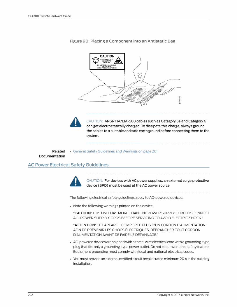
Figure 90: Placing a Component into an Antistatic Bag
6xGE
SFP
0
1
2
3
4
5
CAUTIONELECTROSTATIC
SENSITIVEDEVICES
DO NOT OPEN OR HANDLEEXCEPT AT A
STATIC-FREE WORKSTATION
CAUTION: ANSI/TIA/EIA-568 cables such as Category 5e and Category 6can get electrostatically charged. To dissipate this charge, always groundthe cables to a suitable and safe earth groundbefore connecting them to thesystem.
RelatedDocumentation
General Safety Guidelines andWarnings on page 261•
AC Power Electrical Safety Guidelines
CAUTION: For devices with AC power supplies, an external surge protectivedevice (SPD)must be used at the AC power source.
The following electrical safety guidelines apply to AC-powered devices:
• Note the following warnings printed on the device:
“CAUTION: THIS UNIT HASMORE THANONE POWER SUPPLY CORD. DISCONNECT
ALL POWER SUPPLY CORDS BEFORE SERVICING TO AVOID ELECTRIC SHOCK.”
“ATTENTION: CET APPAREIL COMPORTE PLUS D'UN CORDON D'ALIMENTATION.AFIN DE PRÉVENIR LES CHOCS ÉLECTRIQUES, DÉBRANCHER TOUT CORDON
D'ALIMENTATION AVANT DE FAIRE LE DÉPANNAGE.”
• AC-powereddevicesare shippedwitha three-wireelectrical cordwithagrounding-type
plug that fits only a grounding-typepower outlet. Donot circumvent this safety feature.
Equipment grounding must comply with local and national electrical codes.
• Youmustprovideanexternal certifiedcircuit breaker ratedminimum20A in thebuilding
installation.
Copyright © 2017, Juniper Networks, Inc.292
EX4300 Switch Hardware Guide

• The power cord serves as the main disconnecting device for the AC-powered device.
The socket outlet must be near the AC-powered device and be easily accessible.
• For devices that havemore than one power supply connection, youmust ensure that
all power connections are fully disconnected so that power to the device is completely
removed to prevent electric shock. To disconnect power, unplug all power cords (one
for each power supply).
Power CableWarning (Japanese)
WARNING: The attached power cable is only for this product. Do not use the cable for another product.
RelatedDocumentation
General Safety Guidelines andWarnings on page 261•
• General Electrical Safety Guidelines andWarnings on page 289
• Multiple Power Supplies DisconnectionWarning on page 302
AC Power DisconnectionWarning
WARNING: Before working on the device or near power supplies, unplug allthe power cords from an AC-powered device.
Waarschuwing Voordat u aan een frame of in de nabijheid van voedingenwerkt, dient u bij wisselstroom toestellen de stekker van het netsnoer uit hetstopcontact te halen.
Varoitus Kytke irti vaihtovirtalaitteiden virtajohto, ennen kuin teet mitäänasennuspohjalle tai työskentelet virtalähteiden läheisyydessä.
AttentionAvantde travailler surunchâssisouàproximitéd'unealimentationélectrique, débrancher le cordon d'alimentation des unités en courantalternatif.
Warnung Bevor Sie an einem Chassis oder in der Nähe von Netzgerätenarbeiten, ziehen Sie bei Wechselstromeinheiten das Netzkabel ab bzw.
AvvertenzaPrimadi lavorare suun telaioo intornoadalimentatori, scollegareil cavo di alimentazione sulle unità CA.
293Copyright © 2017, Juniper Networks, Inc.
Chapter 28: Electrical Safety Guidelines andWarnings

Advarsel Før det utføres arbeid på kabinettet eller det arbeides i nærhetenav strømforsyningsenheter, skal strømledningen trekkes ut påvekselstrømsenheter.
AvisoAntesdetrabalharnumchassis,ouantesdetrabalharpertodeunidadesde fornecimento de energia, desligue o cabo de alimentação nas unidadesde corrente alternada.
¡Atención!Antes demanipular el chasis de un equipoo trabajar cerca deunafuentedealimentación, desenchufar el cabledealimentaciónen losequiposde corriente alterna (CA).
Varning! Innanduarbetarmedett chassi eller nära strömförsörjningsenheterskall du för växelströmsenheter dra ur nätsladden.
RelatedDocumentation
General Safety Guidelines andWarnings on page 261•
• General Electrical Safety Guidelines andWarnings on page 289
• AC Power Electrical Safety Guidelines on page 292
DC Power Electrical Safety Guidelines for Switches
This topic applies to hardware devices in the EX Series product family, which includes
EX Series switches and the XRE200 External Routing Engine.
This topic also applies to hardware devices in the QFX Series and to OCX1100 switches.
Copyright © 2017, Juniper Networks, Inc.294
EX4300 Switch Hardware Guide

• A DC-powered device is equipped with a DC terminal block that is rated for the power
requirements of a maximally configured device.
NOTE: Tosupplysufficientpower, terminate theDC inputwiringona facilityDC source that is capable of supplying:
• Minimumof7.5Aat–48VDCforEX2200,EX2300,EX3300,andEX3400switches
• Minimum of 8 A at –48 VDC for EX3200 and EX4200 switches
• Minimum of 20 A at –48 VDC for EX4300, EX4500, EX4550, andQFX10002 switches
• Minimum of 50 A at –48 VDC for EX6210 switches
• Minimum of 60 A at –48 VDC for EX8208, QFX10008 and QFX10016switches
• Minimum of 100 A at –48 VDC for EX8216 switches
• Minimum of 7 A at –48 VDC for QFX3500, EX4600, QFX5100,QFX5110,and QFX5200 devices
• Minimum of 8 A at –48 VDC for QFX3600 devices
• Minimum of 7 A at –48 VDC for OCX1100 switches
Incorporate an easily accessible disconnect device into the facility wiring. Be sure to
connect the ground wire or conduit to a solid office earth ground. A closed loop ring is
recommended for terminating the ground conductor at the ground stud.
• Run two wires from the circuit breaker box to a source of 48 VDC.
• A DC-powered device that is equipped with a DC terminal block is intended only for
installation in a restricted-access location. In the United States, a restricted-access
area isone inaccordancewithArticles 110-16, 110-17, and 110-18of theNational Electrical
Code ANSI/NFPA 70.
NOTE: Primary overcurrent protection is provided by the building circuitbreaker. This breaker must protect against excess currents, short circuits,and earth grounding faults in accordance with NEC ANSI/NFPA 70.
• Ensure that the polarity of the DC input wiring is correct. Under certain conditions,
connections with reversed polarity might trip the primary circuit breaker or damage
the equipment.
• For personal safety, connect the green and yellowwire to safety (earth) ground at both
the device and the supply side of the DC wiring.
295Copyright © 2017, Juniper Networks, Inc.
Chapter 28: Electrical Safety Guidelines andWarnings

• Themarked input voltage of –48 VDC for a DC-powered device is the nominal voltage
associated with the battery circuit, and any higher voltages are only to be associated
with float voltages for the charging function.
• Because the device is a positive ground system, youmust connect the positive lead to
the terminal labeled RTN, the negative lead to the terminal labeled –48 VDC, and the
earth ground to the device grounding points.
RelatedDocumentation
General Safety Guidelines andWarnings on page 261•
• General Electrical Safety Guidelines andWarnings on page 289
• DC Power DisconnectionWarning on page 297
• DC Power Grounding Requirements andWarning on page 298
• DC PowerWiring SequenceWarning on page 299
• DC PowerWiring TerminationsWarning on page 301
• Connecting DC Power to an EX2200 Switch
• Connecting DC Power to an EX2300 Switch
• Connecting DC Power to an EX3200 Switch
• Connecting DC Power to an EX3400 Switch
• Connecting DC Power to an EX4200 Switch
• Connecting DC Power to an EX4300 Switch on page 159
• Connecting DC Power to an EX4500 Switch
• Connecting DC Power to an EX4550 Switch
• Connecting DC Power to an EX4600 Switch
• Connecting DC Power to an EX6200 Switch
• Connecting DC Power to an EX8200 Switch
• Connecting DC Power to an EX9204 Switch
• Connecting DC Power to an EX9208 Switch
• Connecting DC Power to an EX9214 Switch
• Connecting DC Power to an OCX1100 Switch
• Connecting DC Power to an XRE200 External Routing Engine
• Connecting DC Power to a QFX3500, QFX3600, or QFX3600-I Device
• Connecting DC Power to a QFX5100 Device
• Connecting DC Power to a QFX5200
• Connecting DC Power to a QFX10002
• Connecting DC Power to a QFX10000
Copyright © 2017, Juniper Networks, Inc.296
EX4300 Switch Hardware Guide

DC Power DisconnectionWarning
WARNING: Before performing any of the DC power procedures, ensure thatpower is removed from the DC circuit. To ensure that all power is off, locatethe circuit breaker on the panel board that services the DC circuit, switch thecircuit breaker to the OFF position, and tape the device handle of the circuitbreaker in the OFF position.
Waarschuwing Voordat u een van de onderstaande procedures uitvoert,dientu tecontrolerenofdestroomnaarhetgelijkstroomcircuit uitgeschakeldis. Om u ervan te verzekeren dat alle stroomUIT is geschakeld, kiest u op hetschakelbord de stroomverbreker die het gelijkstroom circuit bedient, draaitde stroomverbreker naar de UIT positie en plakt de schakelaarhendel van destroomverbreker met plakband in de UIT positie vast.
Varoitus Varmista, että tasavirtapiirissä ei ole virtaa ennen seuraavientoimenpiteiden suorittamista. Varmistaaksesi, että virta on KATKAISTUtäysin,paikannatasavirrastahuolehtivassakojetaulussasijaitsevasuojakytkin,käännä suojakytkin KATKAISTU-asentoon ja teippaa suojakytkimen varsiniin, että se pysyy KATKAISTU-asennossa.
Attention Avant de pratiquer l'une quelconque des procédures ci-dessous,vérifier que le circuit en courant continu n'est plus sous tension. Pour en êtresûr, localiser ledisjoncteur situésur lepanneaudeserviceducircuit encourantcontinu, placer le disjoncteur enposition fermée (OFF) et, à l'aide d'un rubanadhésif, bloquer la poignée du disjoncteur en position OFF.
Warnung Vor Ausführung der folgenden Vorgänge ist sicherzustellen, daßdie Gleichstromschaltung keinen Strom erhält. Um sicherzustellen, daßsämtlicher Strom abgestellt ist, machen Sie auf der Schalttafel denUnterbrecher für die Gleichstromschaltung ausfindig, stellen Sie denUnterbrecher auf AUS, und kleben Sie den Schaltergriff des Unterbrechersmit Klebeband in der AUS-Stellung fest.
AvvertenzaPrimadi svolgereunaqualsiasidelleprocedureseguenti, verificareche il circuito CC non sia alimentato. Per verificare che tutta l'alimentazionesia scollegata (OFF), individuare l'interruttore automatico sul quadrostrumenti che alimenta il circuito CC, mettere l'interruttore in posizione OFFe fissarlo con nastro adesivo in tale posizione.
Advarsel Før noen av disse prosedyrene utføres, kontroller at strømmen erfrakoblet likestrømkretsen. Sørg for at all strøm er slått AV. Dette gjøres vedå lokalisere strømbryteren på brytertavlen som betjener likestrømkretsen,slå strømbryterenAVog teipebryterhåndtaketpåstrømbryteren iAV-stilling.
AvisoAntes de executar umdos seguintes procedimentos, certifique-se quedesligou a fonte de alimentação de energia do circuito de corrente contínua.Para se assegurar que toda a corrente foi DESLIGADA, localize o disjuntor no
297Copyright © 2017, Juniper Networks, Inc.
Chapter 28: Electrical Safety Guidelines andWarnings

painel que serve o circuito de corrente contínua e coloque-o na posição OFF(Desligado), segurandonessaposiçãoamanivelado interruptor dodisjuntorcom fita isoladora.
¡Atención! Antes de proceder con los siguientes pasos, comprobar que laalimentacióndelcircuitodecorrientecontinua(CC)estécortada(OFF).Paraasegurarse de que toda la alimentación esté cortada (OFF), localizar elinterruptor automático en el panel que alimenta al circuito de corrientecontinua, cambiar el interruptor automático a la posicióndeApagado (OFF),y sujetar con cinta la palanca del interruptor automático en posición deApagado (OFF).
Varning! Innan du utför någon av följande procedurer måste du kontrolleraatt strömförsörjningen till likströmskretsen är bruten. Kontrollera att allströmförsörjning är BRUTEN genomatt slå AV det överspänningsskydd somskyddar likströmskretsen och tejpa fast överspänningsskyddets omkopplarei FRÅN-läget.
RelatedDocumentation
General Safety Guidelines andWarnings on page 261•
• General Electrical Safety Guidelines andWarnings on page 289
• DC Power Electrical Safety Guidelines for Switches on page 294
• DC Power Grounding Requirements andWarning on page 298
• DC PowerWiring SequenceWarning on page 299
• DC PowerWiring TerminationsWarning on page 301
DC Power Grounding Requirements andWarning
An insulatedgroundingconductor that is identical in size to thegroundedandungrounded
branchcircuit supply conductorsbut is identifiablebygreenandyellowstripes is installed
as part of the branch circuit that supplies the device. The grounding conductor is a
separately derived system at the supply transformer or motor generator set.
WARNING: When you install the device, the ground connectionmust alwaysbemade first and disconnected last.
WaarschuwingBij de installatie vanhet toestelmoetdeaardverbindingaltijdhet eerste worden gemaakt en het laatste worden losgemaakt.
Varoitus Laitetta asennettaessa onmaahan yhdistäminen aina tehtäväensiksi ja maadoituksen irti kytkeminen viimeiseksi.
Attention Lors de l'installation de l'appareil, la mise à la terre doit toujoursêtre connectée en premier et déconnectée en dernier.
Copyright © 2017, Juniper Networks, Inc.298
EX4300 Switch Hardware Guide

Warnung Der Erdanschlußmuß bei der Installation der Einheit immer zuersthergestellt und zuletzt abgetrennt werden.
Avvertenza In fase di installazione dell'unità, eseguire sempre per primo ilcollegamento amassa e disconnetterlo per ultimo.
AdvarselNår enheten installeres, må jordledningen alltid tilkobles først ogfrakobles sist.
Aviso Ao instalar a unidade, a ligação à terra deverá ser sempre a primeira aser ligada, e a última a ser desligada.
¡Atención!Al instalar el equipo, conectar la tierra la primera y desconectarlala última.
Varning!Vid installationavenhetenmåste jordledningenalltid anslutas förstoch kopplas bort sist.
RelatedDocumentation
General Safety Guidelines andWarnings on page 261•
• General Electrical Safety Guidelines andWarnings on page 289
• DC Power Electrical Safety Guidelines for Switches on page 294
• DC Power Copper Conductors Warning
• DC Power DisconnectionWarning on page 297
• DC PowerWiring SequenceWarning on page 299
• DC PowerWiring TerminationsWarning on page 301
DC PowerWiring SequenceWarning
WARNING: Wire the DC power supply using the appropriate lugs. Whenconnecting power, the proper wiring sequence is ground to ground, +RTN to+RTN, then –48 V to –48 V.When disconnecting power, the proper wiringsequence is –48 V to –48 V, +RTN to +RTN, then ground to ground. Notethat the ground wire must always be connected first and disconnected last.
WaarschuwingDe juiste bedradingsvolgorde verbonden is aarde naar aarde,+RTN naar +RTN, en –48 V naar – 48 V. De juiste bedradingsvolgordelosgemaakt is en –48 naar –48 V, +RTN naar +RTN, aarde naar aarde.
VaroitusOikea yhdistettava kytkentajarjestys onmaajohtomaajohtoon,+RTN varten +RTN, –48 V varten – 48 V. Oikea irrotettava kytkentajarjestyson –48 V varten – 48 V, +RTN varten +RTN, maajohtomaajohtoon.
Attention Câblez l'approvisionnement d'alimentation CC En utilisant lescrochets appropriés à l'extrémité de câblage. En reliant la puissance, l'ordre
299Copyright © 2017, Juniper Networks, Inc.
Chapter 28: Electrical Safety Guidelines andWarnings

approprié de câblage est rectifié pour rectifier, +RTN à +RTN, puis –48 V à–48 V. En débranchant la puissance, l'ordre approprié de câblage est –48 Và–48V, +RTNà+RTN, a alors rectifié pour rectifier. Notez que le fil demassedevrait toujours être relié d'abord et débranché pour la dernière fois. Notezque le fil demasse devrait toujours être relié d'abord et débranché pour ladernière fois.
WarnungDieStromzufuhr ist nurmit geeignetenRingösenandasDCNetzteilanzuschliessen. Die richtige Anschlusssequenz ist: Erdanschluss zuErdanschluss, +RTN zu +RTN und dann -48V zu -48V. Die richtige Sequenzzum Abtrennen der Stromversorgung ist -48V zu -48V, +RTN zu +RTN unddannErdanschlusszuErdanschluss.Es ist zubeachtendassderErdanschlussimmer zuerst angeschlossen und als letztes abgetrennt wird.
AvvertenzaMostra lamorsettieradellalimentatoreCC.Cablare l'alimentatoreCC usando i connettori adatti all'estremità del cablaggio, come illustrato. Lacorretta sequenza di cablaggio è damassa amassa, da positivo a positivo(da linea ad L) e da negativo a negativo (da neutro aN). Tenere presente cheil filodimassadevesemprevenire collegatoperprimoescollegatoperultimo.
Advarsel Riktig tilkoples tilkoplingssekvens er jord til jord, +RTN til +RTN,–48V til – 48V. Riktig frakoples tilkoplingssekvens er –48V til – 48V, +RTNtil +RTN, jord til jord.
Aviso Ate con alambre la fuente de potencia cc Usando los terminalesapropiados en el extremo del cableado. Al conectar potencia, la secuenciaapropiada del cableado semuele paramoler, +RTNa+RTN, entonces –48Va –48 V. Al desconectar potencia, la secuencia apropiada del cableado es–48 V a –48 V, +RTN a +RTN, entoncesmolió paramoler. Observe que elalambrede tierra sedebeconectar siempreprimeroydesconectarporúltimo.Observe que el alambre de tierra se debe conectar siempre primero ydesconectar por último.
¡Atención!Wire a fonte de alimentaçãodeDCUsandoos talões apropriadosna extremidade da fiação. Ao conectar a potência, a seqüência apropriadada fiação émoída paramoer, +RTN a +RTN, então –48 V a –48 V. Aodesconectar a potência, a seqüência apropriada da fiação é –48 V a –48 V,+RTN a +RTN, moeu então paramoer. Anote que o fio à terra deve sempreser conectado primeiramente e desconectado por último. Anote que o fio àterra deve sempre ser conectado primeiramente e desconectado por último.
Varning! Korrekt kopplingssekvens ar jord till jord, +RTN till +RTN, –48 V till–48V. Korrekt kopplas kopplingssekvens ar –48V till –48V, +RTN till +RTN,jord till jord.
RelatedDocumentation
General Safety Guidelines andWarnings on page 261•
• General Electrical Safety Guidelines andWarnings on page 289
Copyright © 2017, Juniper Networks, Inc.300
EX4300 Switch Hardware Guide

• DC Power Electrical Safety Guidelines for Switches on page 294
• DC Power DisconnectionWarning on page 297
• DC Power Grounding Requirements andWarning on page 298
• DC PowerWiring TerminationsWarning on page 301
DC PowerWiring TerminationsWarning
WARNING: When stranded wiring is required, use approved wiringterminations, such as closed-loop or spade-type with upturned lugs. Theseterminationsmustbe theappropriate size for thewires andmust clampboththe insulation and conductor.
WaarschuwingWanneer geslagen bedrading vereist is, dient u bedrading tegebruiken die voorzien is van goedgekeurde aansluitingspunten, zoals hetgesloten-lus typeofhetgrijperschop typewaarbij deaansluitpuntenomhoogwijzen. Deze aansluitpunten dienen de juistemaat voor de draden te hebbenen dienen zowel de isolatie als de geleider vast te klemmen.
Varoitus Jos säikeellinen johdinon tarpeen, käytähyväksyttyä johdinliitäntää,esimerkiksi suljettua silmukkaa tai kourumaista liitäntää, jossa on ylöspäinkäännetyt kiinnityskorvat. Tällaisten liitäntöjen tulee olla kooltaan johtimiinsopivia ja niiden tulee puristaa yhteen sekä eristeen että johdinosan.
AttentionQuand des fils torsadés sont nécessaires, utiliser des douillesterminales homologuées telles que celles à circuit fermé ou du type à plageouverte avec cosses rebroussées. Ces douilles terminales doivent être de lataille qui convient aux fils et doivent être refermées sur la gaine isolante etsur le conducteur.
WarnungWenn Litzenverdrahtung erforderlich ist, sind zugelasseneVerdrahtungsabschlüsse, z.B. für einen geschlossenen Regelkreis odergabelförmig, mit nach oben gerichteten Kabelschuhen zu verwenden. DieseAbschlüsse solltendie angemesseneGröße für dieDrähtehabenundsowohldie Isolierung als auch den Leiter festklemmen.
AvvertenzaQuando occorre usare trecce, usare connettori omologati, comequelli a occhiello o a forcella con linguette rivolte verso l'alto. I connettoridevono avere lamisura adatta per il cablaggio e devono serrare sia l'isolanteche il conduttore.
AdvarselHvis det er nødvendigmed flertrådede ledninger, brukes godkjenteledningsavslutninger, som for eksempel lukket sløyfe eller spadetypemedoppoverbøyde kabelsko. Disse avslutningene skal ha riktig størrelse i forholdtil ledningene, og skal klemme sammen både isolasjonen og lederen.
AvisoQuando forem requeridasmontagens de instalação eléctrica de cabotorcido,use terminaçõesdecaboaprovadas, tais como, terminaçõesdecabo
301Copyright © 2017, Juniper Networks, Inc.
Chapter 28: Electrical Safety Guidelines andWarnings
em circuito fechado e planas com terminais de orelha voltados para cima.Estas terminações de cabo deverão ser do tamanho apropriado para osrespectivos cabos, e deverão prender simultaneamente o isolamento e o fiocondutor.
¡Atención! Cuando se necesite hilo trenzado, utilizar terminales para cableshomologados, tales como las de tipo "bucle cerrado" o "espada", con laslengüetas de conexión vueltas hacia arriba. Estos terminales deberán ser deltamañoapropiadopara loscablesqueseutilicen, y tendránquesujetar tantoel aislante como el conductor.
Varning!När flertrådiga ledningar krävsmåste godkända ledningskontakteranvändas, t.ex. kabelsko av sluten eller öppen typmed uppåtvänd tapp.Storlekenpådessakontaktermåstevaraavpassad till ledningarnaochmåstekunna hålla både isoleringen och ledaren fastklämda.
RelatedDocumentation
General Safety Guidelines andWarnings on page 261•
• General Electrical Safety Guidelines andWarnings on page 289
• DC Power Electrical Safety Guidelines for Switches on page 294
• DC Power DisconnectionWarning on page 297
• DC Power Grounding Requirements andWarning on page 298
• DC PowerWiring SequenceWarning on page 299
Multiple Power Supplies DisconnectionWarning
WARNING: For a device that hasmore than one power supply connection,youmust ensure that all power connections are fully disconnected so thatpower to the device is completely removed.
RelatedDocumentation
General Safety Guidelines andWarnings on page 261•
• General Electrical Safety Guidelines andWarnings on page 289
• AC Power Electrical Safety Guidelines on page 292
• DC Power Electrical Safety Guidelines for Switches on page 294
TN PowerWarning
WARNING: The device is designed to work with a TN power system.
Copyright © 2017, Juniper Networks, Inc.302
EX4300 Switch Hardware Guide

WaarschuwingHet apparaat is ontworpen om te functionerenmet TNenergiesystemen.
Varoitus Koje on suunniteltu toimimaan TN-sähkövoimajärjestelmienyhteydessä.
Attention Ce dispositif a été conçu pour fonctionner avec des systèmesd'alimentation TN.
WarnungDasGerät ist fürdieVerwendungmitTN-Stromsystemenausgelegt.
Avvertenza Il dispositivo è stato progettato per l'uso con sistemi dialimentazione TN.
AdvarselUtstyret er utfomet til brukmed TN-strømsystemer.
AvisoO dispositivo foi criado para operar com sistemas de corrente TN.
¡Atención! El equipo está diseñado para trabajar con sistemas dealimentación tipo TN.
Varning! Enheten är konstruerad för användning tillsammansmedelkraftssystem av TN-typ.
RelatedDocumentation
• General Safety Guidelines andWarnings on page 261
• General Electrical Safety Guidelines andWarnings on page 289
• Grounded EquipmentWarning on page 276
• Multiple Power Supplies DisconnectionWarning on page 302
303Copyright © 2017, Juniper Networks, Inc.
Chapter 28: Electrical Safety Guidelines andWarnings

Copyright © 2017, Juniper Networks, Inc.304
EX4300 Switch Hardware Guide

CHAPTER 29
Agency Approvals and ComplianceStatements
• Agency Approvals for EX Series Switches on page 305
• Compliance Statements for EMC Requirements for EX Series Switches on page 306
• Compliance Statements for Acoustic Noise for EX Series Switches on page 310
• Statements of Volatility for Juniper Network Devices on page 310
Agency Approvals for EX Series Switches
This topic applies to hardware devices in the EX Series product family, which includes
EX Series switches, the EX Series Redundant Power System (RPS), and the XRE200
External Routing Engine.
These hardware devices comply with the following standards:
• Safety
• CAN/CSA-C22.2 No. 60950-1 Information Technology Equipment
• UL 60950-1 Information Technology Equipment
• EN 60950-1 Information Technology Equipment
• IEC 60950-1 Information Technology Equipment
• EN 60825-1 Safety of Laser Products - Part 1: Equipment classification and
requirements
• EMC
• FCC 47CFR Part 15 Class A (USA)
• EN 55022 Class A Emissions (Europe)
• ICES-003 Class A
• VCCI Class A (Japan)
• AS/NZS CISPR 22 Class A (Australia/New Zealand)
• CISPR 22 Class A
• EN 55024
305Copyright © 2017, Juniper Networks, Inc.

• EN 300386
• EN 61000-3-2 Power Line Harmonics
• EN 61000-3-3 Voltage Fluctuations and Flicker
• EN 61000-4-2 ESD
• EN 61000-4-3 Radiated Immunity
• EN 61000-4-4 EFT
• EN 61000-4-5 Surge
• EN 61000-4-6 Low Frequency Common Immunity
• EN 61000-4-11 Voltage Dips and Sags
RelatedDocumentation
Compliance Statements for EMC Requirements for EX Series Switches on page 306•
• Compliance Statements for Acoustic Noise for EX Series Switches on page 310
Compliance Statements for EMC Requirements for EX Series Switches
This topic applies to hardware devices in the EX Series product family, which includes
EX Series switches, the EX Series Redundant Power System (RPS), and the XRE200
External Routing Engine.
This topic describes the EMC requirements for these hardware devices for:
• Canada on page 306
• European Community on page 307
• Israel on page 307
• Japan on page 307
• Korea on page 308
• United States on page 308
• FCC Part 15 Statement on page 308
• Nonregulatory Environmental Standards on page 309
Canada
This Class A digital apparatus complies with Canadian ICES-003.
Cet appareil numérique de la classe A est conforme à la norme NMB-003 du Canada.
The Industry Canada label identifies certified equipment. This certification means that
the equipment meets certain telecommunications network protective, operational, and
safety requirements. Industry Canada does not guarantee the equipment will operate to
the users’ satisfaction.
Before installing this equipment, users should ensure that it is permissible to connect the
equipment to the facilities of the local telecommunications company. The equipment
Copyright © 2017, Juniper Networks, Inc.306
EX4300 Switch Hardware Guide

must also be installed using an acceptable method of connection. In some cases, the
inside wiring associated with a single line individual service can be extended bymeans
of a certified connector assembly. The customer should be aware that compliance with
the above conditions might not prevent degradation of service in some situations.
Repairs to certified equipment should bemade by an authorized Canadianmaintenance
facility designated by the supplier. Any repairs or alterations made by the user to this
equipment, or equipment malfunctions, might give the telecommunications company
cause to request the user to disconnect the equipment.
CAUTION: Users should not attempt tomake electrical ground connectionsby themselves, but should contact the appropriate inspection authority oran electrician, as appropriate.
Users should ensure for their own protection that the electrical ground connections of
the power utility, telephone lines, and internal metallic water pipe system, if present, are
connected together. This precaution might be particularly important in rural areas.
European Community
This is a Class A device. In a domestic environment this device might cause radio
interference, in which case the user needs to take adequate measures.
Israel
Translation from Hebrew–Warning: This product is Class A. In residential environments,
theproductmaycause radio interference, and in suchasituation, theusermaybe required
to take adequate measures.
Japan
The preceding translates as follows:
This is a Class A device. In a domestic environment this device might cause radio
interference, in which case the user needs to take adequate measures.
VCCI-A
307Copyright © 2017, Juniper Networks, Inc.
Chapter 29: Agency Approvals and Compliance Statements

Korea
Korean Class A Warning g040
913
The preceding translates as follows:
This equipment is Industrial (Class A) electromagnetic wave suitability equipment and
seller or user should takenoticeof it, and this equipment is tobeused in theplacesexcept
for home
United States
The device has been tested and found to comply with the limits for a Class A digital
device, pursuant to Part 15 of the FCC Rules. These limits are designed to provide
reasonable protection against harmful interference when the equipment is operated in
a commercial environment. This equipment generates, uses, and can radiate radio
frequencyenergyand, if not installedandused inaccordancewith the instructionmanual,
might cause harmful interference to radio communications. Operation of this equipment
in a residential area is likely to cause harmful interference, in which case users need to
correct the interference at their own expense.
FCC Part 15 Statement
This equipment has been tested and found to comply with the limits for a Class A digital
device pursuant to Part 15 of the FCC Rules. These limits are designed to provide
reasonable protection against harmful interference in a residential installation. This
equipment generates, uses, and can radiate radio frequency energy and, if not installed
and used in accordance with the instructions, might cause harmful interference to radio
communications. However, there is no guarantee that interference will not occur in a
particular installation.
If this equipment does cause harmful interference to radio or television reception, which
can be determined by turning the equipment off and on, the user is encouraged to try
and correct the interference by one or more of the following measures:
• Reorient or relocate the receiving antenna.
• Increase the separation between the equipment and the receiver.
• Connect the equipment into an outlet on a circuit different from that to which the
receiver is connected.
• Consult the dealer or an experienced radio or TV technician for help.
Copyright © 2017, Juniper Networks, Inc.308
EX4300 Switch Hardware Guide

Nonregulatory Environmental Standards
NEBS compliance—These EX Series switches are Network Equipment Building System(NEBS) compliant:
• EX2200-24T and EX2200-48T
• EX3200-24T, EX3200-48T
• EX3300-24T, EX3300-48T
• EX3400
• EX4200-24T, EX4200-24F, EX4200-24F-S, EX4200-48T and EX4200-48T-S
• EX4300-24T, EX4300-24T-S, EX4300-24P, EX4300-24P-S, EX4300-32F,
EX4300-32F-S, EX4300-48T, EX4300-48T-AFI, EX4300-48T-S, EX4300-48P, and
EX4300-48P-S
• All EX4500 switches with AC power supplies
• EX4550-32T-AFO, EX4550-32T-AFI, EX4550-32F-AFO, EX4550-32F-AFI, and
EX4550-32F-S
• EX4600-40F and EX4600-40F-S
• All EX6200 switches
NOTE: For the EX6200-48P line cards, the intrabuilding ports must useshielded intrabuilding cabling or wiring that is grounded at both ends.
• All EX8200 switches
These switches meet the following NEBS compliance standards:
• SR-3580 NEBS Criteria Levels (Level 4 Compliance)
• GR-1089-CORE:EMCandElectricalSafety forNetworkTelecommunicationsEquipment
• GR-63-CORE: NEBS, Physical Protection
• The equipment is suitable for installation as part of the Common Bonding Network
(CBN).
• The equipment is suitable for installation in locations where the National Electrical
Code (NEC) applies.
• The battery return connection is to be treated as an Isolated DC return (DC-I), as
defined in GR-1089-CORE.
RelatedDocumentation
Agency Approvals for EX Series Switches on page 305•
• Compliance Statements for Acoustic Noise for EX Series Switches on page 310
309Copyright © 2017, Juniper Networks, Inc.
Chapter 29: Agency Approvals and Compliance Statements
Compliance Statements for Acoustic Noise for EX Series Switches
This topic applies to hardware devices in the EX Series product family, which includes
EX Series switches, the EX Series Redundant Power System (RPS), and the XRE200
External Routing Engine.
Maschinenlärminformations-Verordnung - 3. GPSGV, der höchste Schalldruckpegel
beträgt 70 dB(A) oder weniger gemäss EN ISO 7779
Translation:
The emitted sound pressure is below 70 dB(A) per EN ISO 7779.
RelatedDocumentation
Agency Approvals for EX Series Switches on page 305•
• Compliance Statements for EMC Requirements for EX Series Switches on page 306
Statements of Volatility for Juniper Network Devices
A statement of volatility—sometimes known as letter of volatility—identifies the volatile
and non-volatile storage components in Juniper Networks devices, and describes how
to remove non-volatile storage components from the device.
NOTE: Statements of volatility are not available for all Juniper Networksdevices.
EX series:
• EX2200
• EX3300
• EX4200
• EX4300
• EX4550
MX series:
• RE-S-X6-64G Routing Engine
QFX series:
• QFX3008–I
• QFX3100
• QFX3500
• QFX3600
Copyright © 2017, Juniper Networks, Inc.310
EX4300 Switch Hardware Guide

• QFX5100–24Q
• QFX5100–48S6Q
SRX series:
• SRX240H
• SRX650
• SRX1400
• SRX3400 and SRX3600
• SRX5000
311Copyright © 2017, Juniper Networks, Inc.
Chapter 29: Agency Approvals and Compliance Statements

Copyright © 2017, Juniper Networks, Inc.312
EX4300 Switch Hardware Guide


