Page 1
1
Examining Workcell Kinematic Chains to Identify Sources of
Positioning Degradation
Alexander Klinger1, Brian A. Weiss2
1,2National Institute of Standards and Technology (NIST), Gaithersburg, Maryland, 20899, USA
[email protected]
[email protected]
ABSTRACT
Automated industrial workcells are becoming increasingly
complex and varied due to greater accessibility of advanced
robotic and sensing technologies. Degradation monitoring
and diagnostics must advance to reduce the impact of
increased system complexity on troubleshooting faults and
failures and to optimize system operations. A new
methodology is being developed for the design and
implementation of monitoring kinematic chains commonly
found in robot workcells. This method will enable the
identification of degraded components which contribute to
relative positioning accuracy error between moving objects,
tools, devices, and other components. The proposed
methodology is being developed and tested on a six degree of
freedom industrial robot arm workcell use case developed at
the National Institute of Standards and Technology (NIST).
Industrial robot users and integrators can use this method to
examine the kinematic chains within their workcells and
design a key position monitoring implementation. With the
added key position monitoring, degradations can be
identified at a designed resolution allowing for enhanced
maintenance planning and production control. The
methodology will be extended to other manufacturing
workcells in the future.
1. INTRODUCTION
Robotics, along with supporting sensing and automation
technologies, are actively used for a variety of tasks
throughout the manufacturing industry (Ahmad & Plapper,
2016; Chen, Fuhlbrigge, & Li, 2008; Shi, Wang, & Li, 2007).
As robotic and sensor technologies have evolved, the
diversity and complexity of use cases have grown. There is a
need to better understand the health, and consequently, the
wear of these automation systems, as the manufacturing
community increases their reliance on advanced
technologies. Systems can be maintained more efficiently,
leading to a more robust process, if/when advanced health
information is generated.
A critical element of industrial robot workcells is reliable
(inclusive of repeatability) positioning. In many robot
workcells, a six degree of freedom (6DOF) industrial robot
arm is used as a macro positioner for an end effector (i.e.,
tooling mounted to the tool flange of the robot). The tool may
be a gripper in a material handling application or it could be
a welding gun, paint applicator, or tooling that is specific to
other operations (Agheli, Qu, & Nestinger, 2014; Chen et al.,
2008; Weiss & Klinger, 2017). A workcell may be configured
such that end effectors are changed during operations to
enable a single robot to serve as the macro positioner for
multiple tasks. Reliability of positioning accuracy is required
when using industrial robots.
Researchers from the National Institute of Standards and
Technology (NIST) are focused on developing the necessary
measurement science to verify and validate monitoring,
diagnostic, and prognostic technologies to promote enhanced
maintenance and control strategies within manufacturing
operations (Pellegrino, Justiniano, Raghunathan, & Weiss,
2016; Weiss et al., 2015). Part of this effort is focused on
measuring technologies supporting 6DOF robot workcells
(Klinger & Weiss, 2018; Weiss & Klinger, 2017). This article
presents NIST’s development of a new methodology for the
design and implementation of monitoring kinematic chains
commonly found in robotic workcells. This method will
enable the identification of degraded components that
contribute to relative positioning accuracy errors between
moving objects, tools, devices and other components. The
proposed methodology is being developed and tested on a
6DOF industrial robot arm workcell use case developed at
NIST. This methodology will offer a low-cost, minimally
invasive means for a manufacturer to quickly assess the
health of their robot workcell and ascertain where in the
kinematic chain positional errors are originating. Ultimately,
this research will be used to promote industry-driven
standards to verify and validate health monitoring of workcell
technologies (Vogl, Weiss, & Donmez, 2014a, 2014b; Weiss,
Alonzo, & Weinman, 2017).
Alexander Klinger et al. This is an open-access article distributed under
the terms of the Creative Commons Attribution 3.0 United States License,
which permits unrestricted use, distribution, and reproduction in any
medium, provided the original author and source are credited.
Page 2
ANNUAL CONFERENCE OF THE PROGNOSTICS AND HEALTH MANAGEMENT SOCIETY 2018
2
The remainder of this paper is organized as follows. Section
2 presents background on the need for identifying
points/areas of degradation within the kinematic chain along
with some prior work. Section 3 provides a detailed
discussion of the proposed kinematic chain analysis
methodology. Section 4 discusses the kinematic chain
inspection process to identify degradations. Section 5
highlights future work. Finally, Section 6 concludes the paper
and acknowledges future work.
2. BACKGROUND
The Prognostics and Health Management (PHM) community
is focused on advancing monitoring, diagnostic, and
prognostic capabilities to maintain and/or improve asset
availability, product/process quality, and productivity of a
range of operations, including those within manufacturing.
PHM has been actively applied to manufacturing factories
with varying success (Helu & Weiss, 2016; Jin, Siegel, et al.,
2016; Jin, Weiss, Siegel, & Lee, 2016). This has included the
development and implementation of numerous strategies to
minimize reactive maintenance and optimize the balance
between preventive and predictive maintenance (Lee, Lapira,
Bagheri, & Kao, 2013; Lee, Ni, Djurdjanovic, Qiu, & Liao,
2006; Peng, Dong, & Zuo, 2010; Vogl, Weiss, & Helu, 2016).
Most manufacturing robot workcells can be considered
complex systems of systems. The overall physical system can
be broken down into sub-systems, components, sub-
components, etc. Decomposing the physical elements of a
robot workcell into a hierarchy of elements offers a means of
defining boundaries that can drive maintenance activities.
This physical hierarchy can be connected with functional and
informational hierarchies to provide a means of
understanding complex relationships and identifying metrics
and measures of workcell health (Sharp & Weiss, 2018;
Weiss & Qiao, 2017; Weiss, Sharp, & Klinger, 2018). The
more complex a system, the more critical it becomes to
understand its inherent relationships to see how the state of
mechanical degradation of physical elements impacts process
performance.
Research has been performed in monitoring the health,
including positioning, of a robot, itself, separate from the
workcell. Vision and laser tracker systems are two types of
technologies that have been paired with PHM algorithms to
enhance health awareness (Qiao & Weiss, 2017; Spiewak,
Zaiss, & Ludwick, 2013; Wan, Song, Xu, Liu, & Chen,
2018). There is a need to expand the health monitoring
capabilities beyond the robot, itself, and to consider the entire
robot workcell. Understanding and monitoring the
positioning health of all elements of kinematic chains is a
necessary part of a comprehensive PHM system for robot
workcells. Prior research has been performed in monitoring
the health of robot workcells, yet research has not been found
that focuses specifically on monitoring kinematic chain
health. Existing robot monitoring approaches present unique
solutions that are either too high-level and lacking specific
guidance (Lopez-Mellado & Alami, 1990) or rely upon
potentially costly technology (Jokinen & Lastra, 2016;
Novak-Marcincin, Torok, Janak, & Novakova-
Marcincinova, 2014). NIST personnel believe that
monitoring and analyzing the kinematic chain for positional
degradation can be done in a cost-effective and minimally-
intrusive manner to increase benefit for the robot workcell
owners and users.
3. KINEMATIC CHAIN ANALYSIS
Kinematic chains can be documented at various levels of
complexity for the same mechanism. At the most detailed
level, a kinematic chain contains all bodies, including
components and sub-components, fasteners, and other parts.
The documentation of some kinematic chains may only
include links between actuated joints or express entire
actuated assemblies as single links.
It is beneficial to observe multiple points along a kinematic
chain in a serial manipulator to monitor positioning accuracy
and identify the source of positioning errors. By inspecting
repeatability at multiple points along a chain, the source of
repeatability degradation can be narrowed down to the
component(s) located between adjacent inspection points. To
facilitate this, a way of representing a kinematic chain is
needed that provides sufficient detail to choose relevant
inspection points to meet monitoring objectives. To develop
this representation, a suggested starting point is to document
the chain at the component level while identifying the
relationships between components through their interfaces.
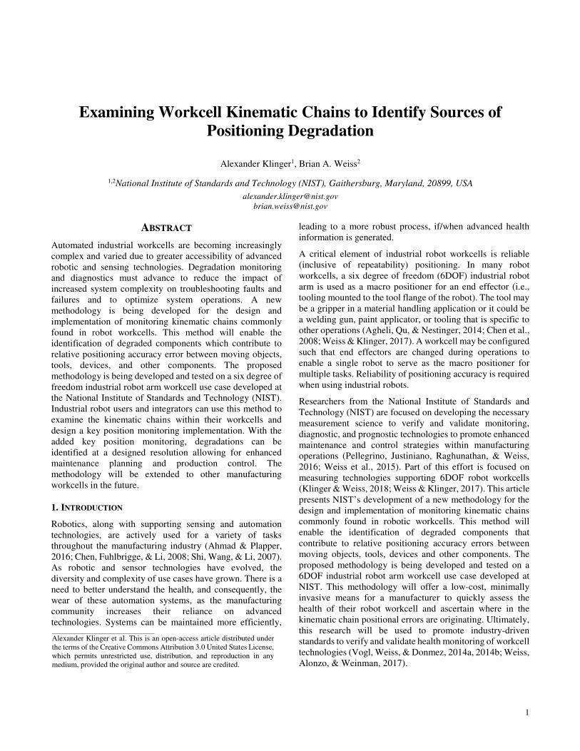
The kinematic chain is made of links which can be connected
to other links or a reference frame. Each component or
element of the system is considered a link in the kinematic
chain. Each link has a left-hand side (LHS) and a right-hand
side (RHS) which correspond to that component’s interfaces
with other links in the chain. It is important to note that LHS
and RHS elements are physical pieces of the link, itself. For
example, if a robot is a link, the LHS would likely be the
robot’s base since that would be physically connected to a
mounting surface and the RHS would likely be the robot’s
tool flange since this is where an end effector would be
joined. At the LHS and RHS boundaries of each link,
permanent connections are represented by brackets ‘[,]’ and
intermittent connections with parenthesis ‘(,)’. For example,
a gripper, which is permanently fixed to a robot tool flange,
will have a ‘[’ on its LHS corresponding to the permanent
connection to a robot and a ‘)’ on its RHS corresponding to
an intermittent connection to a part as shown in Figure 1.
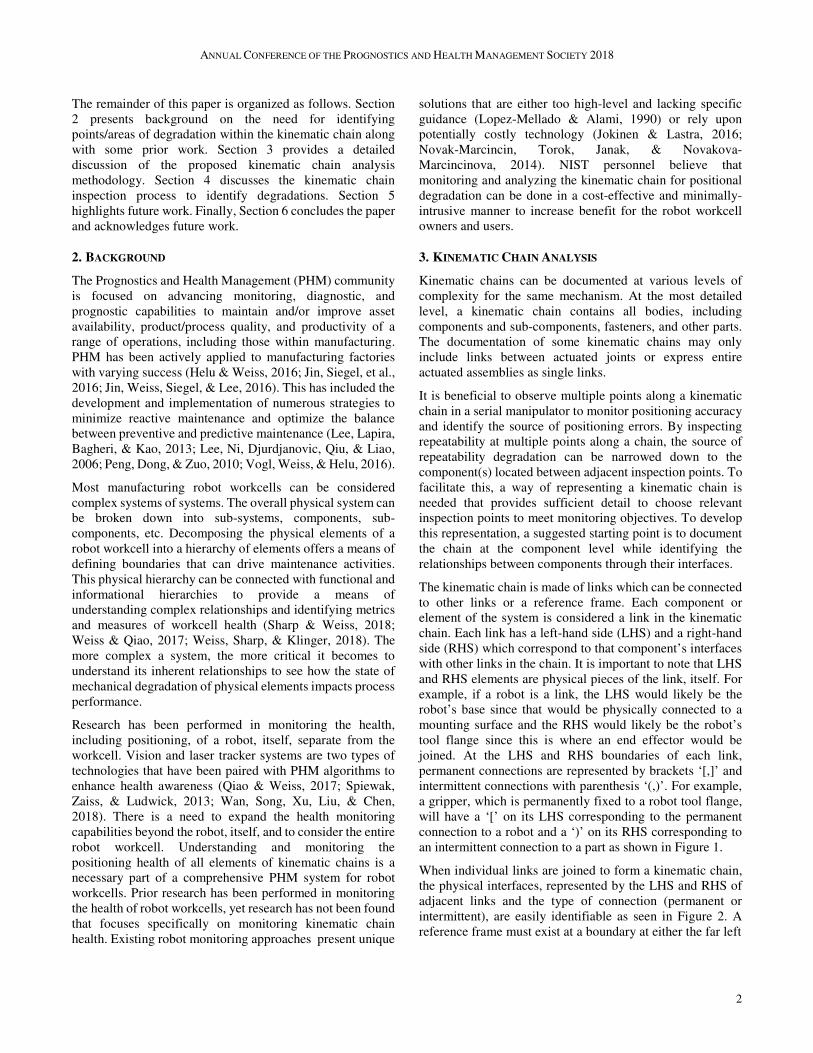
When individual links are joined to form a kinematic chain,
the physical interfaces, represented by the LHS and RHS of
adjacent links and the type of connection (permanent or
intermittent), are easily identifiable as seen in Figure 2. A
reference frame must exist at a boundary at either the far left
Page 3
ANNUAL CONFERENCE OF THE PROGNOSTICS AND HEALTH MANAGEMENT SOCIETY 2018
3
Figure 1. Kinematic chain individual link representation:
(a) generic link, (b) example of a robot with permanent
connections at both interfaces, and (c) example of a gripper
with intermittent connection on RHS
or far right (or both) of the chain to provide a basis of
measurement. Using this convention also allows for the
kinematic chain to be represented in text. A single link can be
represented as [LHS, Link, RHS] or more simply [Link]. For
example, the chain in Figure 2(a) can be represented as
‘Reference] [LHS 1, Link 1, RHS 1] [LHS 2, Link 2, RHS
2)’ or in a simpler form ‘Reference] [Link 1] [Link 2).’
A variety of components are typically chosen by a machine
integrator for specific tasks during industrial robot workcell
design and integration. This variety can pose a challenge in
expressing the range of possible configurations. At
Figure 2. Kinematic chain representation of two links with
key features identified. (a) Generic representation, (b) robot
and gripper example.
minimum, every robotic workcell includes an industrial robot
arm and an end effector. These components will serve as the
starting point of the kinematic chain as shown in Figure 2(b).
Not all kinematic chains remain intact throughout the entirety
of a manufacturing process. In use cases where there are
multiple, swappable end effectors, multiple chains will exist
throughout the overall process. Likewise, an end effector may
perform two or more functions. Each function will generate a
unique kinematic chain which includes the interactions that
are specific to those functions. Additional chains will need to
be documented and analyzed in these scenarios.
Beyond the robot arm and end effector, additional workcell
components are considered part of the kinematic chain if they
impact the positional accuracy of any component or action
within the process. These components include elements that
are not actuated or actively controlled yet are critical in the
relative positioning of parts and equipment during operation.
For example, a hard stop may be used to orient a part. If the
hard stop is not properly positioned, the part will not be
oriented properly when aligned with the stop. Therefore, the
hard stop should be included in the kinematic chain.
Additional components can also include parts being worked
on and the fixturing that is holding them.
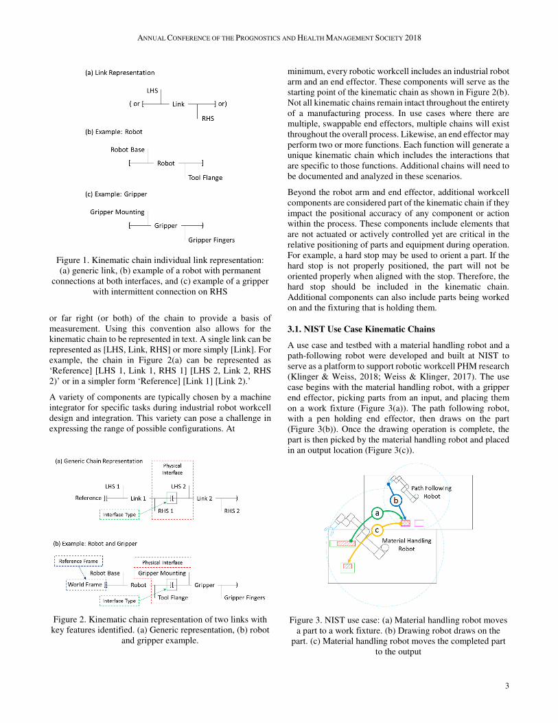
3.1. NIST Use Case Kinematic Chains
A use case and testbed with a material handling robot and a
path-following robot were developed and built at NIST to
serve as a platform to support robotic workcell PHM research
(Klinger & Weiss, 2018; Weiss & Klinger, 2017). The use
case begins with the material handling robot, with a gripper
end effector, picking parts from an input, and placing them
on a work fixture (Figure 3(a)). The path following robot,
with a pen holding end effector, then draws on the part
(Figure 3(b)). Once the drawing operation is complete, the
part is then picked by the material handling robot and placed
in an output location (Figure 3(c)).
Figure 3. NIST use case: (a) Material handling robot moves
a part to a work fixture. (b) Drawing robot draws on the
part. (c) Material handling robot moves the completed part
to the output
Page 4
4
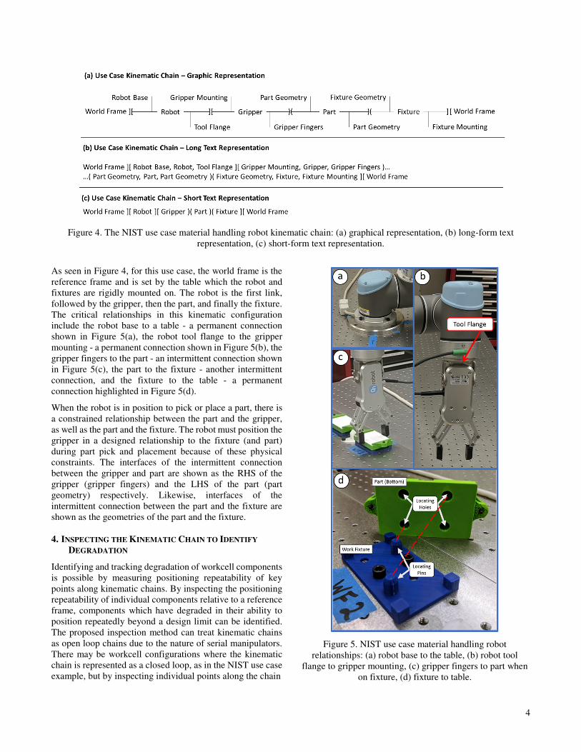
Figure 4. The NIST use case material handling robot kinematic chain: (a) graphical representation, (b) long-form text
representation, (c) short-form text representation.
As seen in Figure 4, for this use case, the world frame is the
reference frame and is set by the table which the robot and
fixtures are rigidly mounted on. The robot is the first link,
followed by the gripper, then the part, and finally the fixture.
The critical relationships in this kinematic configuration
include the robot base to a table - a permanent connection
shown in Figure 5(a), the robot tool flange to the gripper
mounting - a permanent connection shown in Figure 5(b), the
gripper fingers to the part - an intermittent connection shown
in Figure 5(c), the part to the fixture - another intermittent
connection, and the fixture to the table - a permanent
connection highlighted in Figure 5(d).
When the robot is in position to pick or place a part, there is
a constrained relationship between the part and the gripper,
as well as the part and the fixture. The robot must position the
gripper in a designed relationship to the fixture (and part)
during part pick and placement because of these physical
constraints. The interfaces of the intermittent connection
between the gripper and part are shown as the RHS of the
gripper (gripper fingers) and the LHS of the part (part
geometry) respectively. Likewise, interfaces of the
intermittent connection between the part and the fixture are
shown as the geometries of the part and the fixture.
4. INSPECTING THE KINEMATIC CHAIN TO IDENTIFY
DEGRADATION
Identifying and tracking degradation of workcell components
is possible by measuring positioning repeatability of key
points along kinematic chains. By inspecting the positioning
repeatability of individual components relative to a reference
frame, components which have degraded in their ability to
position repeatedly beyond a design limit can be identified.
The proposed inspection method can treat kinematic chains
as open loop chains due to the nature of serial manipulators.
There may be workcell configurations where the kinematic
chain is represented as a closed loop, as in the NIST use case
example, but by inspecting individual points along the chain
Figure 5. NIST use case material handling robot
relationships: (a) robot base to the table, (b) robot tool
flange to gripper mounting, (c) gripper fingers to part when
on fixture, (d) fixture to table.
Page 5
ANNUAL CONFERENCE OF THE PROGNOSTICS AND HEALTH MANAGEMENT SOCIETY 2018
5
this does not pose an issue. In cases where the chain is a
closed loop, which is typically due to multiple components
interfacing directly with the same reference frame as the
robot, inspections may need to be carried out working from
both the LHS and RHS reference frames. This will be
discussed further and through example with the NIST use
case.
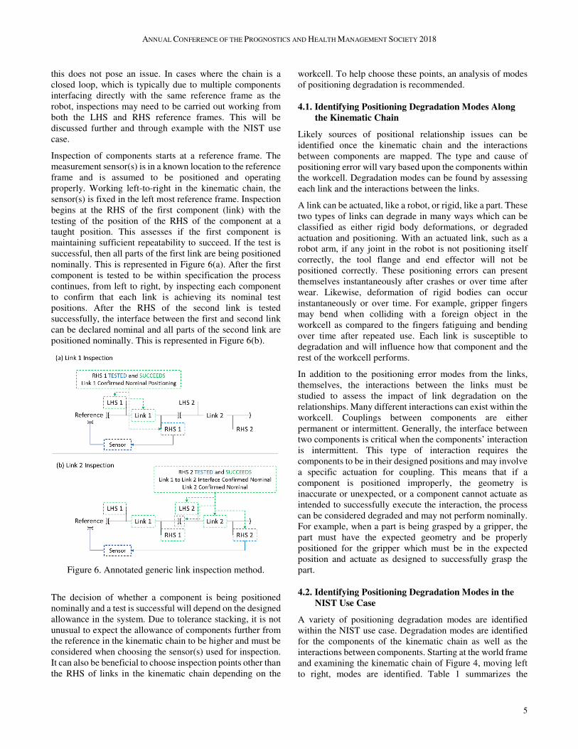
Inspection of components starts at a reference frame. The
measurement sensor(s) is in a known location to the reference
frame and is assumed to be positioned and operating
properly. Working left-to-right in the kinematic chain, the
sensor(s) is fixed in the left most reference frame. Inspection
begins at the RHS of the first component (link) with the
testing of the position of the RHS of the component at a
taught position. This assesses if the first component is
maintaining sufficient repeatability to succeed. If the test is
successful, then all parts of the first link are being positioned
nominally. This is represented in Figure 6(a). After the first
component is tested to be within specification the process
continues, from left to right, by inspecting each component
to confirm that each link is achieving its nominal test
positions. After the RHS of the second link is tested
successfully, the interface between the first and second link
can be declared nominal and all parts of the second link are
positioned nominally. This is represented in Figure 6(b).
Figure 6. Annotated generic link inspection method.
The decision of whether a component is being positioned
nominally and a test is successful will depend on the designed
allowance in the system. Due to tolerance stacking, it is not
unusual to expect the allowance of components further from
the reference in the kinematic chain to be higher and must be
considered when choosing the sensor(s) used for inspection.
It can also be beneficial to choose inspection points other than
the RHS of links in the kinematic chain depending on the
workcell. To help choose these points, an analysis of modes
of positioning degradation is recommended.
4.1. Identifying Positioning Degradation Modes Along
the Kinematic Chain
Likely sources of positional relationship issues can be
identified once the kinematic chain and the interactions
between components are mapped. The type and cause of
positioning error will vary based upon the components within
the workcell. Degradation modes can be found by assessing
each link and the interactions between the links.
A link can be actuated, like a robot, or rigid, like a part. These
two types of links can degrade in many ways which can be
classified as either rigid body deformations, or degraded
actuation and positioning. With an actuated link, such as a
robot arm, if any joint in the robot is not positioning itself
correctly, the tool flange and end effector will not be
positioned correctly. These positioning errors can present
themselves instantaneously after crashes or over time after
wear. Likewise, deformation of rigid bodies can occur
instantaneously or over time. For example, gripper fingers
may bend when colliding with a foreign object in the
workcell as compared to the fingers fatiguing and bending
over time after repeated use. Each link is susceptible to
degradation and will influence how that component and the
rest of the workcell performs.
In addition to the positioning error modes from the links,
themselves, the interactions between the links must be
studied to assess the impact of link degradation on the
relationships. Many different interactions can exist within the
workcell. Couplings between components are either
permanent or intermittent. Generally, the interface between
two components is critical when the components’ interaction
is intermittent. This type of interaction requires the
components to be in their designed positions and may involve
a specific actuation for coupling. This means that if a
component is positioned improperly, the geometry is
inaccurate or unexpected, or a component cannot actuate as
intended to successfully execute the interaction, the process
can be considered degraded and may not perform nominally.
For example, when a part is being grasped by a gripper, the
part must have the expected geometry and be properly
positioned for the gripper which must be in the expected
position and actuate as designed to successfully grasp the
part.
4.2. Identifying Positioning Degradation Modes in the
NIST Use Case
A variety of positioning degradation modes are identified
within the NIST use case. Degradation modes are identified
for the components of the kinematic chain as well as the
interactions between components. Starting at the world frame
and examining the kinematic chain of Figure 4, moving left
to right, modes are identified. Table 1 summarizes the
Page 6
ANNUAL CONFERENCE OF THE PROGNOSTICS AND HEALTH MANAGEMENT SOCIETY 2018
6
identified degradation modes. The modes internal to
components, including robot wear, gripper wear, bad parts,
and fixture wear are expressed as between the LHS and RHS
of their respective components. The connection is assumed as
the only failure mode between two links that are permanently
fixed to one another and other modes are considered as part
of the components. For the intermittent interactions between
the part and the gripper, and the part and the fixture, any of
the components can contribute to positioning error leading to
multiple modes listed.
Table 1. Use case relationships table.
Kinematic Chain Section Degradation
Mode(s)
World Frame ][ Robot Base Loose Connection
[Robot Base, ROBOT, Robot Tool
Flange] Robot Wear
Robot Tool Flange ][ Gripper Mounting Loose Connection
[Gripper Mounting, GRIPPER, Gripper
Fingers] Gripper Wear
Gripper Fingers )( Part Geometry Gripper Wear,
Bad Part*
[ PART ] Bad Part*
Part Geometry )( Fixture Geometry Bad Part*,
Bad Fixture**
[Fixture Geometry, Fixture, Fixture
Mounting] Bad Fixture**
Fixture Mounting ][ World Frame Loose Connection
*From either part inaccuracy or damage
**From either fixture positioning inaccuracy or fixture wear/damage
4.3. Selection of Key Measurement Points to Identify
Points / Areas of Degradation and Inspection
Method
Discrete points along the kinematic chain can be selected for
inspection to detect positioning deviations from nominal or
verify nominal positioning. These key measurement points
need to be tested in one or more degrees of freedom to
determine if they can be positioned within designed limits.
Each point should be chosen to provide information on the
source of a positioning error when measured in a specific
order. As discussed in Section 3, a good starting point in a
LHS-referenced kinematic chain is the RHS of each link in
the chain. Inspecting the RHS of each link will provide
insight into the repeatability of each component. However, if
a component such as an end effector is actuated, it may be
beneficial to inspect both the RHS and another point earlier
in the kinematic chain. Inspecting before an actuation point
of a particular component, the source of repeatability
degradation can be isolated to within the component or to the
connection between the component and the preceding
component. Additionally, an actuated component can be
inspected in multiple configurations or states to provide
further isolation of degradation.
4.4. Selection of Key Measurement Points in the NIST
Use Case
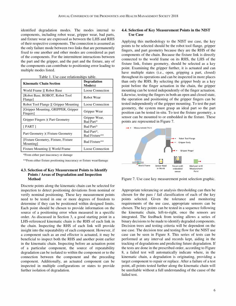
Applying this methodology to the NIST use case, the key
points to be selected should be the robot tool flange, gripper
fingers, and part geometry because they are the RHS of the
components of the chain. Because the fixture link is directly
connected to the world frame on its RHS, the LHS of the
fixture link, fixture geometry, should be selected as a key
point. Examining the gripper further, it is actuated and can
have multiple states (i.e., open, gripping a part, closed)
throughout its operations and can be inspected in more places
than only the RHS. By selecting the gripper body as a key
point before the finger actuation in the chain, the gripper
mounting can be tested independently of the finger actuation.
Likewise, testing the fingers in both an open and closed state,
the operation and positioning of the gripper fingers can be
tested independently of the gripper mounting. To test the part
geometry, the system must grasp an ideal part so the part
position can be tested in-situ. To test the fixture geometry, a
sensor can be mounted to or embedded in the fixture. These
points are represented in Figure 7.
Figure 7. Use case key measurement point selection graphic.
Appropriate tolerancing or analysis thresholding can then be
chosen for the pass / fail classification of each of the key
points selected. Given the tolerance and monitoring
requirements of the use case, appropriate sensors can be
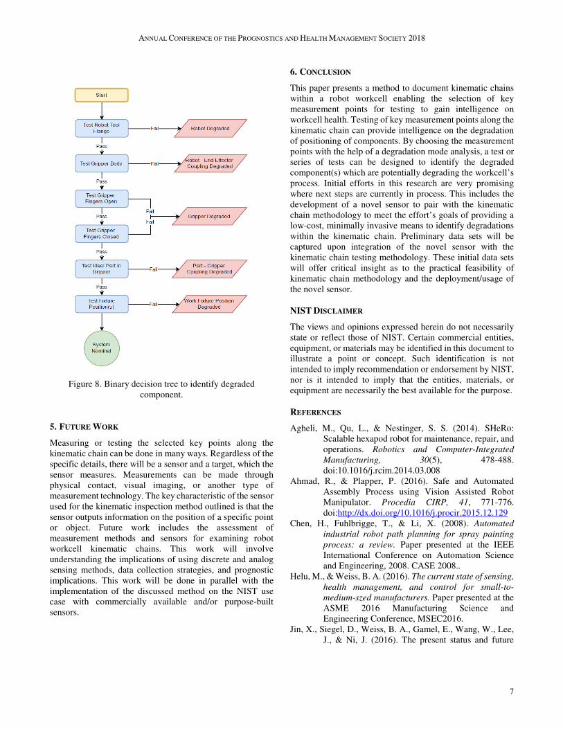
chosen. The key points can be tested in a sequence following
the kinematic chain, left-to-right, once the sensors are
integrated. The feedback from testing allows a series of
binary decisions to be made to identify degraded components.
Decision trees and testing criteria will be dependent on the
use case. The decision tree and testing flow for the NIST use
case can be seen in Figure 8. This series of tests can be
performed at any interval and records kept, aiding in the
tracking of degradations and predicting future degradation. If
the tests are done in the prescribed order, according to Figure
8, a failed test will automatically indicate where, in the
kinematic chain, a degradation is originating, providing a
target component to repair or replace. After a failure of a test
point, all points tested further along the kinematic chain will
be unreliable without a full understanding of the cause of the
failed test.
Page 7
ANNUAL CONFERENCE OF THE PROGNOSTICS AND HEALTH MANAGEMENT SOCIETY 2018
7
Figure 8. Binary decision tree to identify degraded
component.
5. FUTURE WORK
Measuring or testing the selected key points along the
kinematic chain can be done in many ways. Regardless of the
specific details, there will be a sensor and a target, which the
sensor measures. Measurements can be made through
physical contact, visual imaging, or another type of
measurement technology. The key characteristic of the sensor
used for the kinematic inspection method outlined is that the
sensor outputs information on the position of a specific point
or object. Future work includes the assessment of
measurement methods and sensors for examining robot
workcell kinematic chains. This work will involve
understanding the implications of using discrete and analog
sensing methods, data collection strategies, and prognostic
implications. This work will be done in parallel with the
implementation of the discussed method on the NIST use
case with commercially available and/or purpose-built
sensors.
6. CONCLUSION
This paper presents a method to document kinematic chains
within a robot workcell enabling the selection of key
measurement points for testing to gain intelligence on
workcell health. Testing of key measurement points along the
kinematic chain can provide intelligence on the degradation
of positioning of components. By choosing the measurement
points with the help of a degradation mode analysis, a test or
series of tests can be designed to identify the degraded
component(s) which are potentially degrading the workcell’s
process. Initial efforts in this research are very promising
where next steps are currently in process. This includes the
development of a novel sensor to pair with the kinematic
chain methodology to meet the effort’s goals of providing a
low-cost, minimally invasive means to identify degradations
within the kinematic chain. Preliminary data sets will be
captured upon integration of the novel sensor with the
kinematic chain testing methodology. These initial data sets
will offer critical insight as to the practical feasibility of
kinematic chain methodology and the deployment/usage of
the novel sensor.
NIST DISCLAIMER
The views and opinions expressed herein do not necessarily
state or reflect those of NIST. Certain commercial entities,
equipment, or materials may be identified in this document to
illustrate a point or concept. Such identification is not
intended to imply recommendation or endorsement by NIST,
nor is it intended to imply that the entities, materials, or
equipment are necessarily the best available for the purpose.
REFERENCES
Agheli, M., Qu, L., & Nestinger, S. S. (2014). SHeRo:
Scalable hexapod robot for maintenance, repair, and
operations. Robotics and Computer-Integrated
Manufacturing, 30(5), 478-488.
doi:10.1016/j.rcim.2014.03.008
Ahmad, R., & Plapper, P. (2016). Safe and Automated
Assembly Process using Vision Assisted Robot
Manipulator. Procedia CIRP, 41, 771-776.
doi:http://dx.doi.org/10.1016/j.procir.2015.12.129
Chen, H., Fuhlbrigge, T., & Li, X. (2008). Automated
industrial robot path planning for spray painting
process: a review. Paper presented at the IEEE
International Conference on Automation Science
and Engineering, 2008. CASE 2008..
Helu, M., & Weiss, B. A. (2016). The current state of sensing,
health management, and control for small-to-
medium-szed manufacturers. Paper presented at the
ASME 2016 Manufacturing Science and
Engineering Conference, MSEC2016.
Jin, X., Siegel, D., Weiss, B. A., Gamel, E., Wang, W., Lee,
J., & Ni, J. (2016). The present status and future
Page 8
ANNUAL CONFERENCE OF THE PROGNOSTICS AND HEALTH MANAGEMENT SOCIETY 2018
8
growth of maintenance in US manufacturing: results
from a pilot survey. Manufacturing Rev., 3, 10.
Jin, X., Weiss, B. A., Siegel, D., & Lee, J. (2016). Present
Status and Future Growth of Advanced
Maintenance Technology and Strategy in US
Manufacturing. International Journal of
Prognostics and Health Management, 7 (Special
Issue on Smart Manufacturing PHM)(Sp5), 18.
Jokinen, J., & Lastra, J. L. M. (2016). Implementation of
nonintrusive monitoring and fault diagnosis in
industrial robot system. Paper presented at the 2016
IEEE 14th International Conference on Industrial
Informatics (INDIN).
Klinger, A. S., & Weiss, B. A. (2018). Robotic Work Cell Test
Bed to Support Measurement Science for PHM.
Paper presented at the 2018 ASME Manufacturing
Science and Engineering Conference (MSEC),
College Station, Texas.
Lee, J., Lapira, E., Bagheri, B., & Kao, H.-a. (2013). Recent
advances and trends in predictive manufacturing
systems in big data environment. Manufacturing
Letters, 1(1), 38-41.
Lee, J., Ni, J., Djurdjanovic, D., Qiu, H., & Liao, H. (2006).
Intelligent prognostics tools and e-maintenance.
Computers in Industry, 57(6), 476-489.
Lopez-Mellado, E., & Alami, R. (1990). A failure recovery
scheme for assembly workcells. Paper presented at
the 1990 IEEE International Conference on
Robotics and Automation.
Novak-Marcincin, J., Torok, J., Janak, M., & Novakova-
Marcincinova, L. (2014). Interactive Monitoring of
Production Process with Use of Augmented Reality
Technology. Applied Mechanics and Materials,
616, 19.
Pellegrino, J., Justiniano, M., Raghunathan, A., & Weiss, B.
A. (2016). Measurement Science Roadmap for
Prognostics and Health Management for Smart
Manufacturing Systems. NIST Advanced
Manufacturing Seriess (AMS).
Peng, Y., Dong, M., & Zuo, M. J. (2010). Current status of
machine prognostics in condition-based
maintenance: a review. The International Journal of
Advanced Manufacturing Technology, 50(1-4), 297-
313.
Qiao, G., & Weiss, B. A. (2017). Accuracy Degradation
Analysis for Industrial Robot Systems. Paper
presented at the ASME International Manufacturing
Science and Engineering Conference, Los Angeles,
California.
Sharp, M., & Weiss, B. A. (2018). Hierarchical modeling of
a manufacturing work cell to promote
contextualized PHM information across multiple
levels. Manufacturing Letters, 15, 46-49.
Shi, Y. H., Wang, G. R., Li, & G. J. (2007). Adaptive robotic
welding system using laser vision sensing for
underwater engineering. In 2007 IEEE International
Conference on Control and Automation, Vols 1-7
(pp. 1795-1800).
Spiewak, S., Zaiss, C., & Ludwick, S. J. (2013, November
15-21, 2013). High Accuracy, Low-Invasive
Displacement Sensor (HALIDS). Paper presented at
the ASME 2013 International Mechanical
Engineering Congress and Exposition, IMECE
2013, San Diego, CA, United states.
Vogl, G. W., Weiss, B. A., & Donmez, M. A. (2014a).
Standards for prognostics and health management
(PHM) techniques within manufacturing
operations. Paper presented at the Annual
Conference of the Prognostics and Health
Management Society 2014, Fort Worth, Texas,
USA.
Vogl, G. W., Weiss, B. A., & Donmez, M. A. (2014b).
Standards Related to Prognostics and Health
Management (PHM) for Manufacturing (NISTIR
8012). Retrieved from Gaithersburg, Maryland,
USA: http://dx.doi.org/10.6028/NIST.IR.8012
Vogl, G. W., Weiss, B. A., & Helu, M. (2016). A review of
diagnostic and prognostic capabilities and best
practices for manufacturing. Journal of Intelligent
Manufacturing. doi:10.1007/s10845-016-1228-8
Wan, A., Song, L., Xu, J., Liu, S., & Chen, K. (2018).
Calibration and compensation of machine tool
volumetric error using a laser tracker. International
Journal of Machine Tools and Manufacture, 124,
126-133.
Weiss, B. A., Alonzo, D., & Weinman, S. D. (2017).
Summary Report on a Workshop on Advanced
Monitoring, Diagnostics, and Prognostics for
Manufacturing Operations.
Weiss, B. A., & Klinger, A. S. (2017). Identification of
Industrial Robot Arm Work Cell Use Cases and a
Test Bed to Promote Monitoring, Diagnostic, and
Prognostic Technologies. Paper presented at the
2017 Annual Conference of the Prognostics and
Health Management (PHM) Society, St. Petersburg,
FL.
Weiss, B. A., & Qiao, G. (2017). Hierarchical
Decomposition of a Manufacturing Work Cell to
Promote Monitoring, Diagnostics, and Prognostics.
Paper presented at the ASME 2017 International
Manufacturing Science and Engineering
Conference (MSEC2017), Los Angeles, California.
Weiss, B. A., Sharp, M., & Klinger, A. (2018). Developing a
hierarchical decomposition methodology to increase
manufacturing process and equipment health
awareness. Journal of Manufacturing Systems.
Weiss, B. A., Vogl, G. W., Helu, M., Qiao, G., Pellegrino, J.,
Justiniano, M., & Raghunathan, A. (2015).
Measurement Science for Prognostics and Health
Management for Smart Manufacturing Systems:
Key Findings from a Roadmapping Workshop.
Paper presented at the Annual Conference of the
Page 9
ANNUAL CONFERENCE OF THE PROGNOSTICS AND HEALTH MANAGEMENT SOCIETY 2018
9
Prognostics and Health Management Society 2015,
Coronado, CA.
BIOGRAPHIES
Alexander Klinger has a B.S. in
Mechanical Engineering (2013) from
Lehigh University, Bethlehem,
Pennsylvania and a Masters of
Engineering in Mechanical Engineering
(2017) from the University of Maryland,
College Park, Maryland. He is currently a
mechanical engineer working on the
Prognostics, Health Management and Control project within
the Engineering Laboratory (EL) at the National Institute of
Standards and Technology (NIST). Prior to his role at NIST,
he was a mechanical engineer at the United States Postal
Service (USPS) Engineering Headquarters, working on
automation and robotic systems. He has also worked in
various engineering roles in the manufacturing and
entertainment industry.
Dr. Brian A. Weiss has a B.S. in
Mechanical Engineering (2000), Masters
in Engineering (2003), and Ph.D. in
Mechanical Engineering (2012) from the
University of Maryland, College Park,
Maryland. He is currently the Project
Leader of the Prognostics, Health
Management, and Control (PHMC)
project within the Engineering Laboratory (EL) at the
National Institute of Standards and Technology (NIST). Prior
to his leadership role in the PHMC project, he spent 15 years
conducting performance assessments across numerous
military and first response technologies including
autonomous unmanned ground vehicles; tactical applications
operating on Android devices; advanced soldier sensor
technologies; free-form, two-way, speech-to-speech
translation devices for tactical use; urban search and rescue
robots; and bomb disposal robots. He is currently a member
of the American Society of Mechanical Engineers (ASME).
His efforts have earned him numerous awards including a
Department of Commerce Gold Medal (2013), Silver Medal
(2011), Bronze Medals (2004 & 2008), and the Jacob
Rabinow Applied Research Award (2006).