NBSIR 77-1206 Example of A Numeric and Alphanumeric Technique for Conversion from A Small-Scale Computer to A Large-Scale Computer Yui-May Chang Daniel E. Rorrer Center for Building Technology Institute for Applied Technology National Bureau of Standards Washington, D.C. 20234 February 1977 Prepared for Division of Energy, Building Technology and Standards Office of Policy Development and Research Department of Housing and Urban Development Washington, D. C. 20410
Transcript
NBSIR 77-1206
Example of A Numeric andAlphanumeric Technique for
Conversion from A Small-ScaleComputer to A Large-ScaleComputer
Yui-May ChangDaniel E. Rorrer
Center for Building Technology
Institute for Applied Technology
National Bureau of Standards
Washington, D.C. 20234
February 1977
Prepared for
Division of Energy, Building Technology and StandardsOffice of Policy Development and ResearchDepartment of Housing and Urban DevelopmentWashington, D. C. 20410
NBSIR 77-1206
EXAMPLE OF A NUMERIC ANDALPHANUMERIC TECHNIQUE FORCONVERSION FROM A SMALL-SCALECOMPUTER TO A LARGE-SCALECOMPUTER
Yui-May ChangDaniel E. Rorrer
Center for Building Technology
Institute for Applied Technology
National Bureau of Standards
Washington, D. C. 20234
February 1 977
Prepared for
Division of Energy, Building Technology and Standards
Office of Policy Development and Research
Department of Housing and urban Development
Washington, D. C. 20410
U.S. DEPARTMENT OF COMMERCE, Juanita M. Kreps, Secretary
Dr. Betsy Ancker-Johnson, Assistant Secretary for Science and Technology
NATIONAL BUREAU OF STANDARDS, Ernest Ambler, Acting Director
TABLE OF CONTENTS
Page
1. INTRODUCTION 1
1.1 Purpose 1
1.2 Background 2
1.3 Approach and Scope 2
2. SELECTION OF DATA FORMAT AND MAGNETIC TAPE DRIVES. ... 3
3. DESCRIPTION OF WORD FORMAT CHARACTERISTIC 3
3 . 1 Real Number 3
3.2 ASCII Character 5
4 . SOFTWARE INTERFACE 7
4.1 Real Number 7
4.1.1 Seven-Track Magnetic Tape 7
4.1.2 Nine-Track Magnetic Tape 10
4.2 ASCII Character 11
ACKNOWLEDGEMENTS 11
APPENDIX A. Hexadecimal and Octal 14
APPENDIX B. Subroutine for Real Number Interfacing 15
APPENDIX C. Program for ASCII Interfacing 17
REFERENCES 20
i
EXAMPLE OF A NUMERIC AND ALPHANUMERIC
TECHNIQUE FOR CONVERSION FROM A SMALL-SCALE
COMPUTER TO A LARGE-SCALE COMPUTER
Yui-May Chang
and
Daniel E. Rorrer
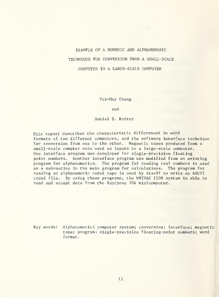
This report describes the characteristic differences in word
formats of two different computers, and the software interface techniquefor conversion from one to the other. Magnetic tapes produced from a
small-scale compter vrere used as inputs to a large-scale computer.
One interface program was developed for single-precision floatingpoint numbers. Another interface program was modified from an existingprogram for alphanumerics. The program for reading real numbers is usedas a subroutine in the main program for calculations. The program forreading an alphanumeric coded tape is used by itself to write an ASCIIcoded file. By using these programs, the UNIVAC 1108 system is able to
read and accept data from the Raytheon 704 minicomputer.
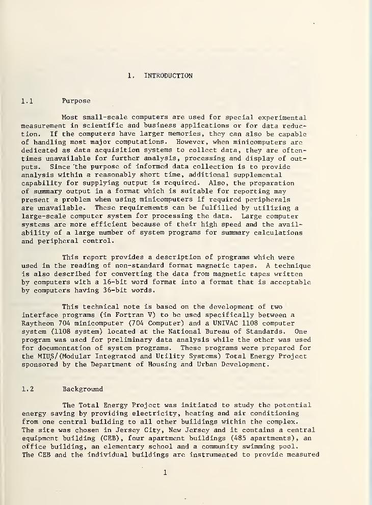
Most small-scale computers are used for special experimentalmeasurement in scientific and business applications or for data reduc-tion. If the computers have larger memories, they can also be capableof handling most major computations. However, when minicomputers arededicated as data acquisition systems to collect data, they are often-times unavailable for further analysis, processing and display of out-puts. Since the purpose of informed data collection is to provideanalysis within a reasonably short time, additional supplementalcapability for supplying output is required. Also, the preparationof summary output in a format which is suitable for reporting maypresent a problem when using minicomputers if required peripheralsare unavailable. These requirements can be fulfilled by utilizing a
large-scale computer system for processing the data. Large computersystems are more efficient because of their high speed and the avail-ability of a large number of system programs for summary calculationsand peripheral control.
This report provides a description of programs which wereused in the reading of non-standard format magnetic tapes. A techniqueis also described for converting the data from magnetic tapes writtenby computers with a 16-bit word format into a format that is acceptableby computers having 36-bit words.
This technical note is based on the development of two
interface programs (in Fortran V) to be used specifically between a
Raytheon 704 minicomputer (704 Computer) and a UNIVAC 1108 computersystem (1108 system) located at the National Bureau of Standards. Oneprogram was used for preliminary data analysis while the other was usedfor documentation of system programs. These programs were prepared for
the MIUS/ (Modular Integrated and Utility Systems) Total Energy Projectsponsored by the Department of Housing and Urban Development.
1.2 Background
The Total Energy Project was initiated to study the potentialenergy saving by providing electricity, heating and air conditioningfrom one central building to all other buildings within the complex.
The site was chosen in Jersey City, New Jersey and it contains a centralequipment building (CEB), four apartment buildings (485 apartments), an
office building, an elementary school and a community swimming pool.
The CEB and the individual buildings are instrumented to provide measured
1
data from various systems—such as electrical, heating and cooling
—
for system performance analysis and evaluation. The data acquisitionsystem (DAS), located inside the CEB consists 169 channels of CEBmeasurements and 112 channels of measurements from other buildings.These measurements are all related to physical parameters, such as flow,
temperature, pressure, power, voltage, frequency, etc. The total energysystem is being operated continuously and the data are being collectedby the DAS scanning every five minutes. All signals coming from thetransducers as analog voltages are digitalized by the analog to digitalconverter and written on the nine-track magnetic tape (raw tape) in
EBCDIC* . The 704 computer is employed to obtain required informationfrom the raw tape.
At the early stage of data collection, the 704 computer wascommitted to trouble shooting instrumentation of individual mechanicalsystems of different buildings. Simultaneously, monthly summary calcula-tions, printouts and graphic plottings were also required in order to
evaluate the total energy system performance. Therefore, afjter the rawtape was edited, the 704 computer was used to create another tape (eitherseven-track or nine-track) in binary code for utilizing the 1108 system.
One interface program was developed to provide a capability of
printing or plotting real number data (in engineering units). The other(alphanumeric) was used for the dual purpose of document modification of
software system programs of the 704 computer and in total energy systemperformance reporting.
1.3 Approach and Scope
The bit configurations of the 704 computer and the 1108 systemare different from each other. There were no available interface programsto provide the necessary processing capability. This report presents a
detailed description to meet the requirements for the 1108 system to
accept information written on magnetic tapes by the 704 computer.
The program for numerical data is used as a subroutine in thesingle-precision floating-point conversion. A main program is requiredto call this subroutine and to perform subsequent processing for analysis,plotting or printing. The program for alphanumeric conversion willwrite an ASCII (American Standard Code for Information Interchange) filein the 1108 system. This file can be printed out by control cards orother programs.
*Extended Binary Coded Decimal Interchange Code. Coding alphanumericdata where 8 bits represent each character.
2
Magnetic tapes written by the 704 computer were analyzed for
format on a bit-by-bit basis. After the tapes are read into the 1108system, the bits are manipulated in order that the output can be directlyaccepted by the 1108 system format. For other projects, this work wouldbe available as an illustrative working example of the approach necessaryto transfer data from one system to another. It is also anticipated thatsimilar techniques could be used for other specific computer interfacing.
2. SELECTION OF DATA FORMAT AND MAGNETIC TAPE DRIVES
Real numbers and alphanumeric characters produced by a 704
computer have various format representations when written on magnetictapes. The single-precision floating-point output format for realnumbers was chosen since it was sufficient to serve the purpose for
future analysis, and since it was presently being written on a seven-track magnetic tape. Other numerical data formats such as integers,double-precision, and mid-precision* were not required, and interfaceprograms for their conversions were not written. Additionally, numericalconversion routines for nine-track magnetic tape input were not considered;however, a preliminary conversion routine has been written. Alphanumericcharacters were written in ASCII format on a nine-track magnetic tape by
a 704 computer. The nine-track tape was chosen for alphanumerics becauseof the existence of a one-to-one correspondence in the bit structure of
an ASCII character and a nine-track magnetic tape frame. If a seven-track tape had been chosen for alphanumerics, an additional conversionfrom octal fieldata to ASCII format would have to be made.
3. DESCRIPTION OF WORD FORMAT CHARACTERISTIC
3.1 Real Number
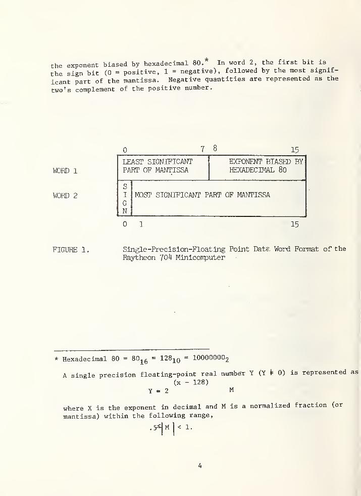
The 704 computer word is 16 bits in length and it takes two
data words to form a single-precision floating-point number [1].** As
shown in Figure 1, the first eight bits of word 1 contain the least
significant part of the mantissa and the last eight bits contain the
* In the 704 computer, a mid-precision floating point number is formed
by three data words and a range of + 10^ with significant of 9 digits.
** See Reference at end of text.
3
the exponent biased by hexadecimal 80.* In word 2, the first bit is
the sign bit (0 = positive, 1 = negative), followed by the most signif-
icant part of the mantissa. Negative quantities are represented as the
two’s complement of the positive number.
0 7 8 15
WORD 1
LEAST SIGNIFICANTPART OF MANTISSA
EXPONENT BIASED BYHEXADECIMAL 80
S
WORD 2 I
GN
MOST SIGNIFICANT PART OF MANTISSA
0 1 15
FIGURE 1. Single-Precision-Floating Point Date. Word Format of the
Raytheon 70*J Minicomputer
* Hexadecimal 80 = 80.^ - 128-^q - IOOOOOOO2
A single precision floating-point real number Y (Y P 0) is represented
(x - 128)
Y - 2 M
where X is the exponent in decimal and M is
mantissa) within the following range.
1.5^M 1 .
a normalized fraction (or
as
4
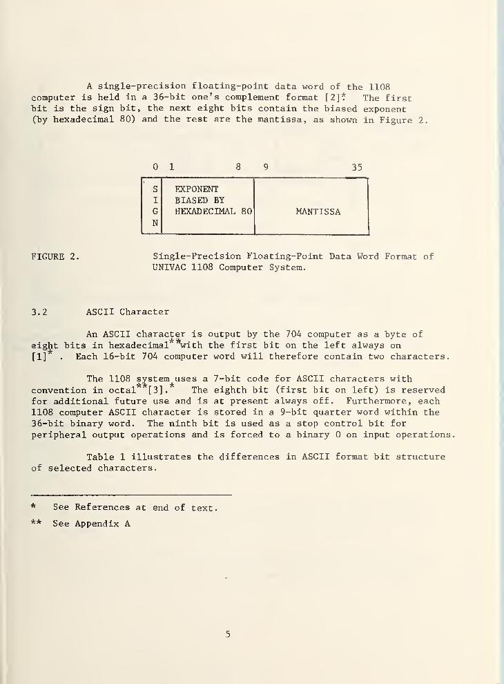
A single-precision floating-point data word of the 1108computer is held in a 36-bit one's complement format [2]? The firstbit is the sign bit, the next eight bits contain the biased exponent(by hexadecimal 80) and the rest are the mantissa, as shown in Figure 2.
0 1 8 9 35
s EXPONENTI BIASED BY
G HEXADECIMAL 80 MANTISSAN
FIGURE 2. Single-Precision Floating-Point Data Word Format ofUNIVAC 1108 Computer System.
3.2 ASCII Character
An ASCII character is output by the 704 computer as a byte of
eight bits inhexadecimal** *with the first bit on the left always on
[1] . Each 16-bit 704 computer word will therefore contain two characters.
The 1108 system uses a 7-bit code for ASCII characters withconvention in octal [3]. The eighth bit (first bit on left) is reservedfor additional future use and is at present always off. Furthermore, each1108 computer ASCII character is stored in a 9-bit quarter word within the
36-bit binary word. The ninth bit is used as a stop control bit for
peripheral output operations and is forced to a binary 0 on input operations.
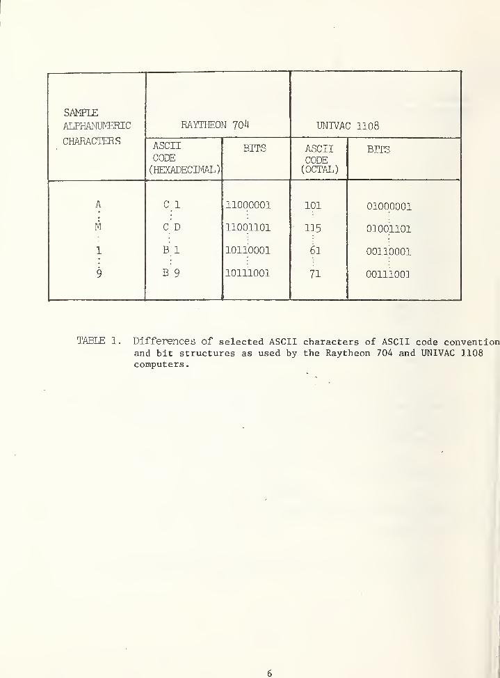
Table 1 illustrates the differences in ASCII format bit structureof selected characters.
* See References at end of text.
** See Appendix A
5
SAMPLE
ALPHANUMERIC
CHARACTERS
RAYTHEON 70^4 UNIVAC 1108
ASCIICODE(HEXADECIMAL)
BITS ASCIICODE(OCTAL)
BITS
A Ci 11000001 101 01000001
M CD 11001101 115 01001101
1 B 1 10110001 61 00110001
9 B 9 10111001 71 00111001
TABLE 1. Differences of selected ASCII characters of ASCII code conventionand bit structures as used by the Raytheon 704 and UNIVAC 1108computers
.
6
4 . SOFTWARE INTERFACE
4 . 1 Real Number
4.1.1 Seven Track Magnetic Tape
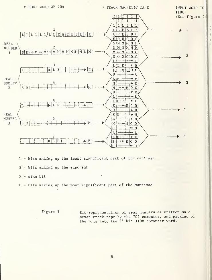
The output of the binary code written on a seven trackmagnetic tape (six tracks for data and one track for parity bits)by the 704 computer is shown in Figure 3 as follows:
1) The first two frames (12 bits) of the record are all l's
(12 bits).
2) Each four frames after the first two, when considered as
24 bits, contain a memory word of 16 bits followed byeight unused bits which are set to 0.
When the 1108 system reads the seven-track magnetic tape, it
will read six frames at a time and pack the bits as input words of
36 bits in length (see Figure 4a) . These input words do not have anymeanings in the 1108 system since they are not in its word format. Inorder to read and convert real numbers generated by the 704 computer,a subroutine RD704T* has been developed for the 1108 system. ThisFortran V routine reads the bit-by-bit configuration of the input tape,decodes it, and manipulates it to the word format of the 1108 Fortran Vsystem (see Figure 4b)
.
RD704T will read one record consisting of many frames fromthe tape whenever it is called. Subroutine NTRAN** and function FLD***(field) are used by RD704T to read the tape and manipulate the bitsrespectively. As shown in Figure 4a, the first group of five inputwords (word 1 through word 5) to the 1108 system contains the firstthree complete real numbers. By using the FLD function, RD704T
* See Appendix B
** TEXTPROCESS * LIB. NTRAN is a Fortran subroutine to read a magnetictape and pack all the bits into each 36-bit memory word of the 1108system.
*** FLD is used to access the bit string of a computer word (36 bits)
.
The form FLD (i,k,e) means to access k bits of bit string e startingfrom the i^ bit of e. The bits are counted from left to right withleft most bit is bit 0.
7
MEMORY WORD OF 704 7 TRACK MAGNETIC TAPE INPUT WORD TO1108
L = bits making up the least significant part of the mantissa
E = bits making up the exponent
S = sign bit
M - bits making up the most significant part of the mantissa
Figure 3 Bit representation of real numbers as written on a
seven-track tape by the 704 computer, and packing of
the bits into the 36-bit 1108 computer word.
8
1
2
3
4
5
1
2
3
I
I
INPUT WORD TO 1108
Figure 4a Bit representations after packing the seven-track tape into the 1108 system .
OUTPUT WORD FROM 1108
s E E E E E E E E M M M M M M M M m|m| m M M M M L L L L L L L!0 q 0 0 RTOUT(l)s F
l
F M —}
—
— M T [l 0^ 0 _RTOUT (2 )
RTOUT (3)s E E M"
rt~ M L'*
L n'
0_
.. r u__
Figure 4b Bit representation of the original real numbersafter decoding and manipulation.
9
arranges these real numbers into three output words (word 1 throughword 3), shown in Figure 4b. As an example, the first output word(R0UT(1)) will have the arrangements as follows:
1) First sign bit (S) at bit 0.
2) First group of eight (8) exponent bits (E) at bit 1
through bit 8.
3) First group of fifteen (15) most significant part ofmantissa bits (M) at bit 9 through bit 23.
4) First group of eight (8) least significant part ofmantissa bits (L) at bit 24 through bit 31.
5) Leave bit 32 through bit 35 empty (or as 0)
.
The second and third output words are arranged in the samemanner as the first one by using second group and third group of
respective bits instead. The fifth input word has the same formatas the first one and it also contains a part of the fourth real number.Therefore, the second group of five input words is from word 5 throughword 9. After the manipulation, three output words (word 4 throughword 6) will represent the fourth, fifth and sixth real numbers of thetape.
RD704T essentially takes five input words (with overlapping),and arranges them into three output data words, as shown in Figure 4b.
Negative quantities are additionally changed from two’s complement to
one's complement format. The output of the conversion is placed in thearray RTOUT (N)
.
4.1.2 Nine-Track Magnetic Tape
Each frame of the nine-track magnetic tape (eight tracks fordata and one track for parity bits) produced by the 704 computer consistedof 8 bits (one byte) from the 16 bits of one word of memory. The 1108system packs each word into 36 bits, which is the same in seven-tracktapes. A preliminary program has been written to perform these nine-track input conversions; however, further debugging and test runs willbe necessary before using.
10
4.2 ASCII Character
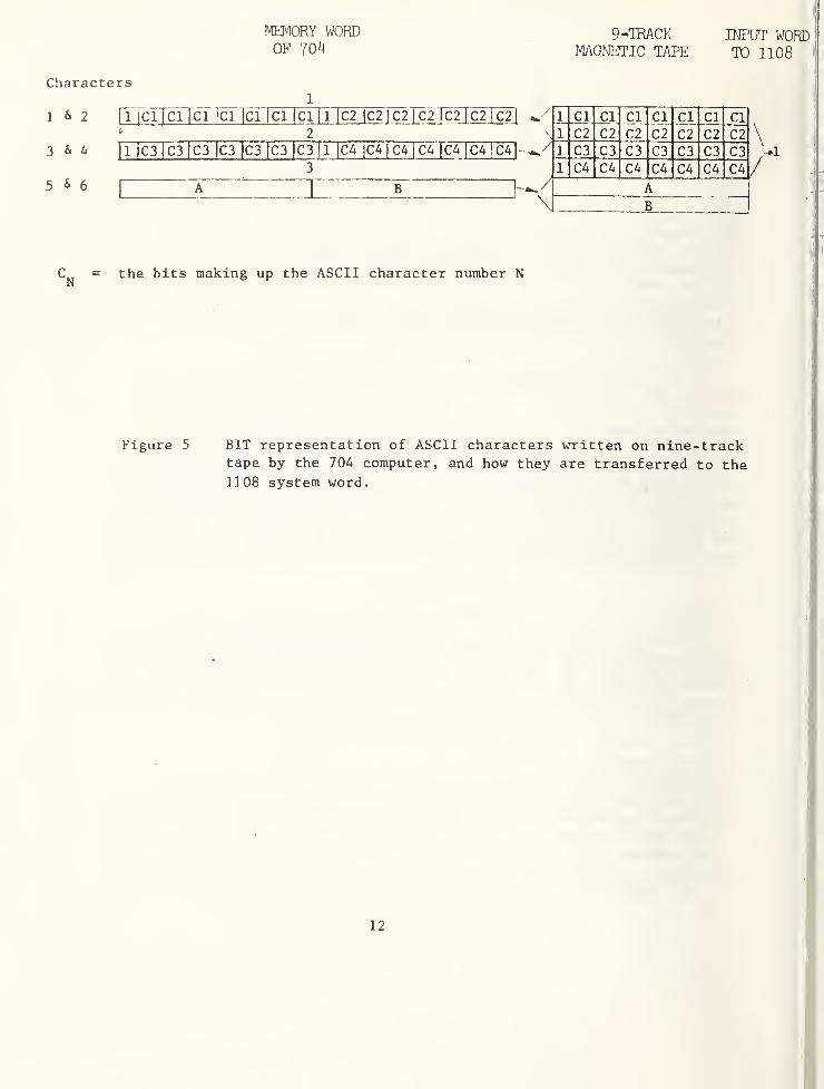
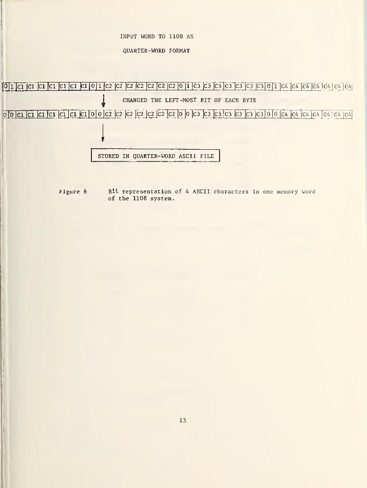
The bit structure of ASCII code produced by the 704 computeris only different from that used in the 1108 system when the left-mostbit is considered (see Table 1). Each frame of the nine-track magnetictape contains one ASCII character (eight bits), as shown in Figure 5.
The program TEXT* in Fortran V is a modified program based on an existingprogram (ASCFLD)** for the 1108 system to read the tape produced by the704 computer and to write an internal ASCII (1108) file. TEXT willread one record of the tape produced by the 704 computer, change theleft-most bit of each frame (byte) and store it in a quarter-word ASCIIfile of the 1108 system (see Figure 6). The reading of the tape willcontinue until an end-of-file mark on tape is detected.
There are numerous ways for the 1108 system to output theASCII file (for example, EDITOR (ED) or PRINT (PRT) could be used toprint the entire file). In the case of report preparation or systemprogram documentation, it is necessary to write a short program to
control the printing format (with options to change number of linesper page, start a new page, etc.). If only upper-case characters areconsidered, an ordinary READ statement of FORTRAN will convert theASCII code to Fieldata by the 1108 system internally for line printeroutputs. However, if both upper- and lower-case characters are required,the subroutine AREAD*** could be used. It is therefore left to theuser's imagination as to how the converted data could best be used.
ACKNOWLEDGEMENTS
The authors would like to express grateful appreciation toDarcy P. Barnett who helped to identify and modify existing libraryprograms of the 1108 system in order for them to be used. Specialthanks to Larry Galowin and Paul Kopetka for their many helpful suggestionsfor clarity in the presentation of this technique.
* See Appendix C
TEXTPROCESS*LIB. ASCFLD is a program developed by the ComputerService Division of NBS to read a nine-track magnetic tape writtenin ASCII or EBCDIC and to write a seven-or nine-track tape inFieldata.
*** IN TEXTPROCESS*LIB.
11
MEMORY WORDOF 704
9-TRACKMAGNETIC TAPE
INPUT WORDTO 1108
Characters
1 & 2 [T [Cl1ClTci ]C1 lcTTcTfci |
l~[c2 |C2|C2 |C2jc2jc:
11 2
5 & 6
3
x:
1 Cl Cl Cl Cl Cl Cl Cl
1 C2 C2 C2 C2 C2 C2 C2C3 C3 C3 C3 C3 C3 C3
1 C4 C4 C4 C4 C4 C4 C4-I if
C^ = the bits making up the ASCII character number N
1
Figure 5 BIT representation of ASCII characters written on nine-tracktape by the 704 computer, and how they are transferred to the1108 system word.
Figure 6 Bit representation of A ASCII characters in one memory wordof the 1108 system.
APPENDIX A - HEXADECIMAL AND OCTAL
Hexadecimal is a number system of base 16. The symbolsare 0 through 9 and A through F.
Examples
:
Binary Hexadecimal Decimal
0000 0 0
1001 9 9
1010 A 10
1111 F 15
10000 10 16
Octal is a number system of base 8. The symbols are
0 through 7.
Examples
:
inary Octal Decimal
000 0 0
010 2 2
100 4 4
111 7 7
1000 10 8
14
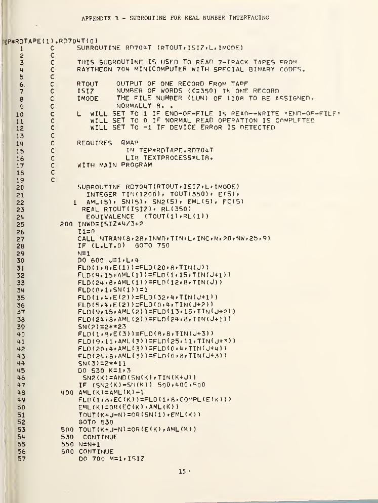
APPENDIX B - SUBROUTINE FOR REAL NUMBER INTERFACING
EP*RDTAPE(1) • RD704T ( 0
)
1 C SUBROUTINE RP704T (RTOUT* ISI7»L, ImOPE)
3 C THIS SUBROUTINE IS USED TO REAP 7-TPACK TAPES CPOM4c
C RAYTHEON 704 MINICOMPUTER WITH SPECIAL BINARY CODES.D
6
L
c RTOUT OUTPUT OF ONE RECORD FROM TAPE7 c ISIZ NUMRER OF WORDS (<=350 ) TN ONE RECORD8 c IMODE THE FILE number (LUN) of 110b to re assigned*9 c NORMALLY 8. .
10 c L WILL SET TO 1 IF END-OF-FILE Is REAP—WRITE * ENO-OF-11 c WILL SET TO 0 IF NORMAL READ OPERATION IS COMPLETED12 c WILL SET TO -1 IF DEVICE ERROR IS DETECTED13 c
14 c REQUIRES OMAP15 c IN TEP*RDTAPE.RD704T16 c LIB TEXTPR0CESS*LIB.17 c WITH MAIN PROGRAM18 c
19 c
202122232425 200
SUBROUTINE RD704T ( RTOUT * I SI Z » L * I MODE
)
INTEGER TIN (1200) * TOUT(350)* E(5)*L AML(5)» SN ( 5
41 FLD (9*11* AML ( 3 ) ) =FLD ( 25 * 1 1 * T IN < J+^ >
)
42 FLD (20 *4* AML (3) ) =FLD ( 0 » 4 » TIN ( J+4 )
)
43 FLD (24*8* AML ( 3 ) ) =FLD ( 0 * 8 * TI N ( J+3 )
)
44 SN ( 3 ) =2**1
1
45 DO 530 K = 1 »
3
46 SN2(K)=AND(SN(K) *TIN(K+J)
)
47 IF (SN2(K)-SM(K) ) 500*400*80048 400 AML(K)=AML(K)-149 FLD ( 1 » 8 * EC ( K ) )=FLD(1*8*C0MPL(E(K) )
)
50 EML (K)=OR (EC (K) * AML ( K )
)
51 TOUT ( K +J-N ) =OR ( SN ( 1 ) * EML ( K )
)
52 GOTO 53053 500 TOUT ( K+J-N) =OR ( E ( K ) * AML(K)
)
54 530 continue55 550 N=N+156 600 CONTINUE57 DO 700 M= 1 * I S I
Z
15
58596061626364656667686970
END PRT
700 RTOUT ( M ) =RL
(
M)
IF(L) 704,704,702702 L=0
GOTO 900 :
704 L=1GOTO Q00
750 IF ( L + 3 ) 860 * 860 , 800800 WR ITE ( 6 » 850
)
850 FORMAT (* END OF FILE*
)
GOTO 704860 L=-l900 RETURN
END
QFIN NIFE
16
APPENDIX C - PROGRAM FOR ASCII INTERFACING
EP*RDTAPE(1) • TFXT ( 0
)
1
2
345
6
_7_89
1011
15161718
IMPLICIT INTFGER(A-Z)
READ A NINE TRACK TAPE WRITTEN IN ASCII ( HFXADFCIMAL
)
AND WRITE A FILE (OR TAPE) IN ASCIT (OCTAL)
REQUIRES OMAPLIB TFXTPR0CESS*LIR.
USES ASC I I/GPSDC TO FIELDAT
A
GPSDC (COL/ROW)TRANSLATION
FIELDAT A
12 C n 12/15 TO n OCTAL 7613 C A 12/4 TO A OCTAL 0414 C RS 1/14 TO OCTAL 77
CAVEATS13 X20 C STOPS ON TAPE MARK ON INPUT TAPE* WRITES TWO SUCCESSIVE TAPE MARKS21 C OUTPUT * BACKSPACES OUTPUT TO RETWFFN TAPE MARKS.22 C
23 C BLOCKS LESS THAN 1 CHARACTERS LONG ON INPUT ARE SKTPPFD. STANDARD24 C * NOISE * CRITERION25 C
26 C STOPS ON END OF OUTPUT TAPE LEAVING INPUT TAPE EXTENDED27 C
28 C29 C INPUT UNIT = 7
30 C
31 C OUTPUT UNIT = 8
32 C
33 C SET BUFFER SIZES34 C
35 PARAMETER MAXCHR = 4500 S' MAX INPUT BLOCK IN CHARACTERS36 C37 PARAMETER IDIM=2* ( ( MAXCHR- 1
)
/9 ) +?38 PARAMETER otdtm=maxchp/6+i39 PARAMETER WKniM=MAXCHR/4-*-l40 DIMENSION INPUT ( ID IM) * OUTPUT ( OTDTM) .WRK(WKDIM)41 DATA ABLANK/0040040040040/42 C43 nmax=maxchr44 C
45 C SET INPUT 7* OUTPUT 8
46 C
i47 L I =748 L0=849 C
50 c CHECK DEVICE TYPE , 9 TRACK UNTT 8^9 EQUIVALENT51 c52 CALL NTPAN(LI *21 » ID)53 IF ( ID.EQ.5 .OR. ID. EG. 6 .OR. TD.FO.ll54 . .OR. ID.FQ.12 .OR. ID.E0.13)GO To 30255 WRITE (6*300)56 300 FORMAT( IX* ’FORCED HALT » TNPIJT DEVICE WRONG*)57 RETURN 0
17
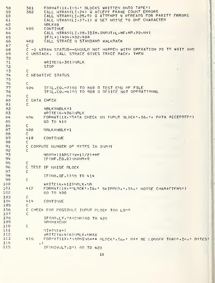
58 301 F0RMAT(1X» I1Q» • BLOCKS WRITTEN ONTO TAPE*)59 302 CALL NTRAN ( L I » 24 ) Q ACCEPT FRAME COUNT ERRORS60 CALL NTRAN(LI»25»9) 0 ATTFMPT 9 REREADS FOR PARITY FRRORS61 CALL NTRAN ( L I » 27 » 1 ) 0 SET NOISE ^0 ONE CHARACTER62 NBLK=063 400 CONTINUE64 CALL NTRAN (LI »28» IDIM» INPUT » L » MF » MP » 20 » NW
)
65 IF(L+1)404?402»40866 402 CALL STRACE 0 STANDARD WALKRACK67 C
68 C -1 NTRAN STATUS—SHOULD NOT HAPPEN WITH OPFRATION 20 TO WAIT AMD69 C UNSTACK. CALL STRACE GIVES TRACE RACK t THEN70 C71 WRXTE(6*301)NRLK72 STOP73 C
74 C NEGATIVE STATUS7576 C
77 404 IF ( L . EQ • -2 ) GO TO 800 Q TEST END OF FILE78 IF ( L . EQ. -4 ) GO TO 900 0 DEVICE NOT OPFRATTONAL79 C
80 C DATA CHECK81 C
82 NBLK=NBLK+183 WRITE(6r406)NRLK84 406 FORMAT ( IX ? ’DATA CHECK ON TNPUT BLOCK *»I6»»» DATA ACCEPTED*)85 GO TO 41086 C87 408 NRLK=NBLK+188 C89 410 CONTINUE90 C
91 C COMPUTE NUMBER Or BYTES IN INPUT92 C^3 NR=9* ( IAPS(NW-1 ) /2 ) +MF94 IF(MF.EQ.0)NR=NR+995 C
96 C TEST IF NOISE BLOCK97 C98 IFfNB.GE. 1 ) GO TO 41499 c
106 C CHECK FOR POSSIBLE INPUT BLOCK TOO LOuG107 C
108 IF (NB.LT
«
MAXCHR)GO TO 420109 NR=MAXCHR110 C
111 NIW=NIW+]112 WR I TE
(
6 * 4 1
6
) N8LK » NMAX113 416 FORMAT ( 1X» « WARMING*** BLOCK* »Tfo»* MAY RE LONGFP THAN *
I
G
.
'!
114 . )
115 IF
(
N I W • LT . 20 ) GO TO 420
18
116 WR ITE ( 6 » 4 1 8
)
117 418 FORMAT ( IX * * *** LAST OF TOO LONG WARNINGS * ONLY 20118 GO TO 800119 420 CONTINUE120 C
121 C COMPUTE LAST WORD TO BE USED IN OUTPUT AMD SPACE FTLL122 C
123 N0W=NB/4 Q OUTPUT WILL BE OUABTFR WORD ASCTI124 IF ( MOD ( NB * 4 ) • NE • 0 ) NOW=NOW+
1
125 WRK ( NOW ) =ABLANK126 OUTPUT ( NOW )=ARLANK127 C
128 CALL QWUP ( INPUT » 1 * NB * WRK » 1
)
129 C
130131132133134_135136137138139140141142143144
C TURN OFF FIRST BIT» KEEP AS QUARTER WORD ASCIIC
CALL BITOFF (WRK* NOW » OUTPUT)C
C WRITE OUTPUTC
CALL APRNTA(LO»l» NOW * 01 ITPUT ) Q ALTFRN ATE ASCII PRINT FILEGO TO 400
C END OF FILE ON INPUT.C ENDFILE OUTPUT TAPE AND MOVE BACK ONE800 CONTINUE
CALL ERTRAN(6» *QBRKPT ft . *) a CLOSE ALTERMATF ASCII FILEWRITE (6*301) NBLKSTOP
C DEVICE ERROR145 900 WRITE ( 6» 901 )
L
146 901 FORMAT (* DEVICE ERROR ON INPi
147 GO TO 800148 SUBROUTINE BTTOFF ( IN » NOW » OUT)149 DIMENSION IN ( NOW
)
t OUT ( NOW
)
150 DATA SEVENR/0177177177177/151 DO 1000 NN— 1 » NOW152 loon OUT ( NN ) =AND ( SEVFNB » IN ( NN )
)
153 RETURN154 C
155 ENDEND PRT
QBRKPT PRINTS
19
REFERENCES
[1] Raytheon 704 Computer User’s Manual
[2] NBS Computer User’s Guide
[3] UNIVAC 1100 Series EXEC 8 Hardware/Software Summary
20
NBS-1 14A (REV. 7-73)
U .S. DEPT. OF COMM.
BIBLIOGRAPHIC DATASHEET
1. PUBLIC ATION OR REPORT NO.
NBSIR 77-12Q6 6Q2. Gov’t Accession
No.3. Recipient’s Accession No.
4. TITLE AND SUBTITLE
Example of a Numeric and Alphanumeric Technique for
Conversion from a Small-Scale Computer to a Large-Scale
Computer
5. Publication Date
6. Performing Organization Code
7. AUTHOR(S)
Yui-May Chang and Daniel E. Rorrer8 . Performin 8 O rgan. Report No.
9. PERFORMING ORGANIZATION NAME AND ADDRESS
NATIONAL BUREAU OF STANDARDSDEPARTMENT OF COMMERCEWASHINGTON, D.C. 20234
10. Project/Task/Work Unit No.
462638211. Contract/Grant No.
12. Sponsoring Organization Name and Complete Address (Street,City, State, ZIP)
Division of Energy, Building Technology and StandardsOffice of Policy Development and Research
Department of Housing and Urban DevelopmentWashington, D.C. 20410
13. Type of Report & PeriodCovered
3/75-5/75 h 2/76-3/7614. Sponsoring Agency Code
15. SUPPLEMENTARY NOTES
16. ABSTRACT (A 200-word or less factual summary of most significant information. If document includes a significant
bibliography or literature survey, mention it here.)
This report describes the characteristic differences in word formats
of two different computers, and the software interface technique for conversionfrom one to the other. Magnetic tapes produced from a small-scale computer wereused as inputs to a large-scale computer. One interface program was developed forSingle-precision floating point numbers. Another interface program was modifiedfrom an existing program for alphanumerics . The program for reading real numbers is
used as a subroutine in the main program for calculations. The program for readingan alphanumeric coded tape is used by itself to write an ASCII coded file. By
using these programs, large-scale computers are able to read and accept datafrom small-scale computers.
17. KEY WORDS (six to twelve entries; alphabetical order; capitalize only the first letter of the first key word unless a proper
name; separated by semicolons
)
Alphanumeric, computer system; conversion; interface; magnetic tape; program, single-precision floating-point numbers; word format.