Example Single - Line Diagram for a SolarEdge ® string inverter system (with power optimizers) 40A SolarEdge Power Optimizer cable/#10 AWG Cu PV Wire, and a solid #6 copper EGC extending from J-box to roof racking/modules/optimizers, wiring in free-air under modules meter Soladeck J-box (2) #10 AWG THWN-2 Cu, with #10 AWG Cu EGC, ¾” EMT, wiring in attic (3) #8 AWG THWN-2 Cu, with #10 AWG Cu EGC, ¾” EMT AC disconnect located next to inverter if inverter is not next to 40A AC breaker. Otherwise, disconnect is not required (per the NEC, but may be required per the utility). SE 7600W inverter Inverter’s DC disconnect (25) 265W SolarWorld Modules (each module with its own Power Optmizer) Service conductors extending to utility Existing Loads Existing Service panelboard Note: this wiring diagram is simply an example. Diagrams may vary.
Transcript
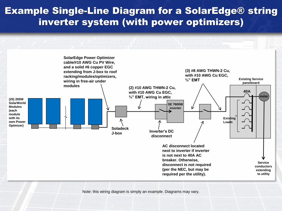
Example Single-Line Diagram for a SolarEdge® string
inverter system (with power optimizers)
40A
SolarEdge Power Optimizer
cable/#10 AWG Cu PV Wire,
and a solid #6 copper EGC
extending from J-box to roof
racking/modules/optimizers,
wiring in free-air under
modules
meter
Soladeck
J-box
(2) #10 AWG THWN-2 Cu,
with #10 AWG Cu EGC,
¾” EMT, wiring in attic
(3) #8 AWG THWN-2 Cu,
with #10 AWG Cu EGC,
¾” EMT
AC disconnect located
next to inverter if inverter
is not next to 40A AC
breaker. Otherwise,
disconnect is not required
(per the NEC, but may be
required per the utility).
SE 7600W
inverter
Inverter’s DC
disconnect
(25) 265W
SolarWorld
Modules
(each
module
with its
own Power
Optmizer)
Service
conductors
extending
to utility
Existing
Loads
Existing Service
panelboard
Note: this wiring diagram is simply an example. Diagrams may vary.
Example Single-Line Diagram (for a
micro inverter system)
#12 AWG TCER trunk
cable which includes a
#12 AWG Cu EGC.
Soladeck
J-box (for
transition of
trunk cable
to NM
cable.
Three separate #12 AWG
3-wire NM cable ran
through attic.
(3) #8 AWG THWN-2 Cu,
with #10 AWG Cu EGC,
¾” EMT
AC disconnect (as shown)
is not required per the
NEC, but may be required
per the utility.
60A rated AC combiner
panelboard (dedicated
only for solar PV
(9) #12 AWG
Cu THWN-2
with #12 AWG
EGC, in ¾”
EMT leading
from roof
eave down to
AC combiner.
(13) 265W
SolarWorld
Modules each
connecting to
its own
Enphase
M250 micro
inverter.
(13) 265W
SolarWorld
Modules each
connecting to
its own
Enphase M250
micro inverter.
(10) 265W
SolarWorld
Modules each
connecting to
its own
Enphase
M250 micro
inverter.
45A
Service
conductors
extending
to utility
Existing
Loads
Existing Service
panelboard
meter
J-box mounted
at roof eave (for
transition of NM
cable to THWN-2
wire in conduit.
20A
20A
20A
Note: this wiring diagram is simply an example. Diagrams may vary.
Grid-tied PV System With Battery
Backup (example diagram)
#10 AWG Cu PV Wire, and a solid
#6 copper EGC extending from J-
box to roof racking/modules,
wiring in free-air under modules
meter
Soladeck
J-box
(4) #10 AWG THWN-2
Cu, with #10 AWG Cu
EGC, ¾” EMT, wiring
in attic
(3) #8 AWG THWN-2 Cu,
with #10 AWG Cu EGC,
¾” EMT
AC disconnect located
next to inverter if
inverter is not next to
40A AC breaker.
Otherwise, disconnect
is not required (per
the NEC, but may be
required per the
utility).
Inverter’s DC
disconnect
(10) 265W
SolarWorld
modules in
series.
(10) 265W
SolarWorld
modules in
series.
Tesla®
Powerwall 2®
battery
enclosure
Service
conductors
extending
to utility
Note: Rapid shutdown equipment and wiring not shown in this diagram but
may be required depending on the type of battery system to be installed.
Existing Service
panelboard
Note: this wiring diagram is simply an example. Diagrams may vary.
40A
Existing
Loads
SolarCity® H6
Hybrid Inverter
Inverter provides
two 25A DC fuses
For protection of
battery conductors
100A rated critical
load panel
AC
disconnect
for critical
load panel
(Battery enclosure to be located next to
inverter unless a 25A DC fused disconnect
is provided next to the battery enclosure for
protection of battery conductors)
(2) #10 AWG THWN-2
Cu, with #10 AWG Cu
EGC, ¾” EMT
35A breaker
with clip holding
breaker in place
(3) #8 AWG
THWN-2 Cu,
with #10 AWG
Cu EGC, ¾”
EMT
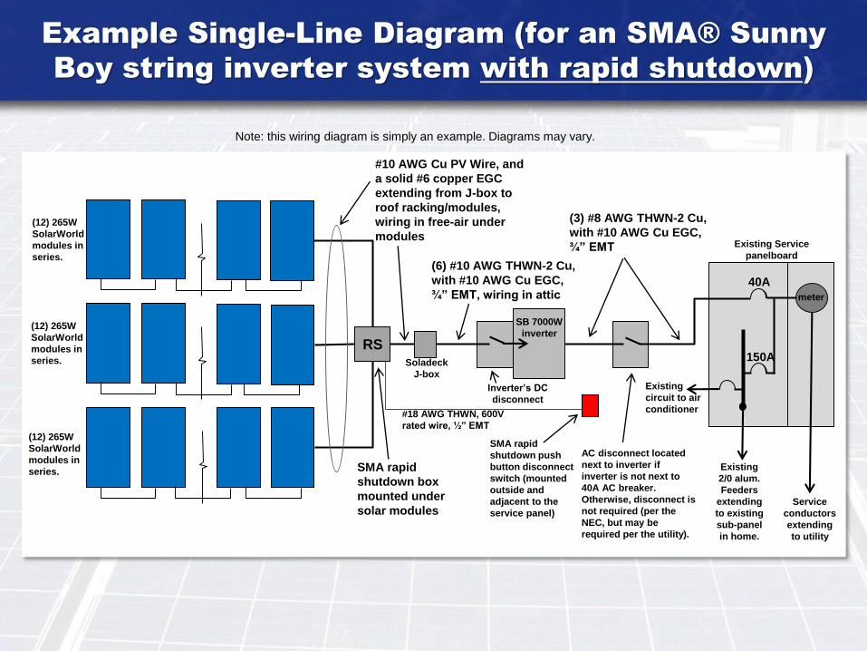
Example Single-Line Diagram (for an SMA® Sunny
Boy string inverter system with rapid shutdown)
40A
150A
#10 AWG Cu PV Wire, and
a solid #6 copper EGC
extending from J-box to
roof racking/modules,
wiring in free-air under
modules
meter
Soladeck
J-box
(6) #10 AWG THWN-2 Cu,
with #10 AWG Cu EGC,
¾” EMT, wiring in attic
(3) #8 AWG THWN-2 Cu,
with #10 AWG Cu EGC,
¾” EMT
AC disconnect located
next to inverter if
inverter is not next to
40A AC breaker.
Otherwise, disconnect is
not required (per the
NEC, but may be
required per the utility).
SB 7000W
inverter
Inverter’s DC
disconnect
(12) 265W
SolarWorld
modules in
series.
(12) 265W
SolarWorld
modules in
series.
(12) 265W
SolarWorld
modules in
series.Existing
2/0 alum.
Feeders
extending
to existing
sub-panel
in home.
Service
conductors
extending
to utility
Existing
circuit to air
conditioner
Existing Service
panelboard
Note: this wiring diagram is simply an example. Diagrams may vary.
SMA rapid
shutdown box
mounted under
solar modules
RS
SMA rapid
shutdown push
button disconnect
switch (mounted
outside and
adjacent to the
service panel)
#18 AWG THWN, 600V
rated wire, ½” EMT
Site plan example (for an SMA Sunny Boy®
inverter system)
A rapid shutdown equipment
may also need to be shown on
the site plan if the PV system
is required to have such
system.
Location of
SMA rapid
shutdown
disconnect
switch
Location of
service
panelboard
Location of
SMA Sunny
Boy® inverter
(in garage –
East wall)
A site plan is required
for all solar PV plan
submittals and must
show locations of all
equipment. Solar PV modules (panels) cannot
be installed over or block any attic
vents, plumbing vents, furnace or
water heater vents etc.
All wiring must be properly
supported by devices or
mechanical means designed and
listed for such use and wiring must
be permanently and completely
held off of the roof surface. See
NEC 110.2, 110.3(A), 110.3(B),
and 300.4. Please be aware that
zip ties are typically not allowed
since they are easily broken and
do not provide a reliable method of
supporting wires up off of the roof.
Roof racking support spacing not
to exceed 4’ spacing. All supports
must be staggered from one row
of racking to the next so not all
supports are bearing on the same
trusses.
This site plan is an example ONLY and site plans may vary.
Flashed roof
J-boxes
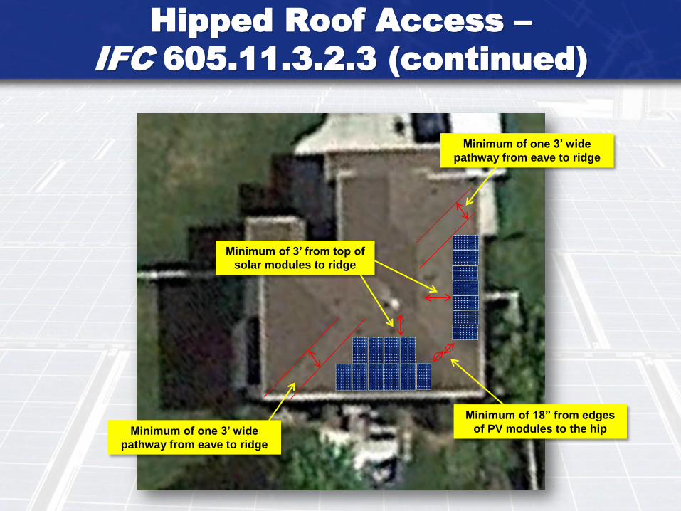
Hipped Roof Access –
IFC 605.11.3.2.3 (continued)
Minimum of 3’ from top of
solar modules to ridge
Minimum of one 3’ wide
pathway from eave to ridge
Minimum of one 3’ wide
pathway from eave to ridge
Minimum of 18” from edges
of PV modules to the hip
Please provide the following signage requirements on the plans (and specify on theplans the location where each sign will be mounted): Please be aware that not everysign noted below is required depending on the type of system to be installed - see WC3detailed checklists for details.
A. Please specify on the plans that all signage must be permanently attached and beweather resistant/sunlight resistant and cannot be hand-written.
B. A sign is required at the service panel stating that the home has a solar PV system asan additional power source. NEC 705.10.
C. A sign is required at the home’s service meter panelboard noting the location of theinverter if the inverter is not located next to the utility service panel. NEC 690.4(D) andNEC 705.10.
D. A sign is required at the main PV system disconnect labeling it as such. NEC690.14(C)(2).
E. For the backfed PV breaker at the existing panelboard, please specify a sign isrequired next to such breaker and states the following: “Warning, Inverter OutputConnection, Do Not Relocate This Overcurrent Device.” This is required per NEC705.12(D)(7).
F. Please specify a sign is required at the service panelboard noting the total rated ACamps and AC voltage of the PV system. NEC 690.54.
G. A sign is required at the inverter noting the total DC system STC rated max current(Impp), the rated max DC voltage (Vmpp), the DC open circuit voltage (Voc) which hasbeen increased for coldest possible outside temperature, and DC short circuit current(Isc). NEC 690.53.
H. Specify that any conduits, enclosures, or MC cable that contain DC circuits shall bemarked on their exterior with the wording “WARNING: PHOTOVOLTAIC POWERSOURCE.” The markings shall be provided at every enclosure, every 10’ along conduitor MC cable, and at each side of where the conduit or cable passes through a wall, floor,or any other partition. The markings shall be permanently affixed and visible afterinstallation. NEC 690.31(E)(3-4)
I. There must be a sign located at the service equipment which notes the following: “PHOTOVOLTAIC SYSTEM EQUIPPED WITH RAPID SHUTDOWN.” The sign must bereflective, with all letters capitalized, and letters are at least 3/8” in height. Wording mustalso be white on a red background. Please specify this information on the plans. SeeNEC 690.56(C).
J. A sign is required to be provided adjacent to the “rapid shutdown” disconnect(s)labeling it/them as such (NEC 690.12 and 690.56(C)). Please specify this on the plans.
Signage requirements
J. A sign is required to be provided adjacent on on the rapid shutdown disconnect(s)labeling it/them as "Rapid Shutdown Switch for Solar PV System," per NEC 690.56(C)(3).Please specify this on the plans.
690.13(B).
705.12(B)(2)(3)(b).
690.31(G).
(see also next sheet for additional rapid shutdown signage requirements).
This sign required at service panel ifstring- level rapid shutdown is provided.
This sign required at service panel if module-level rapid shutdown is provided.
INVE
RTER
S
www.solaredge.us
SolarEdge Single Phase Inverters For North America SE3000A-US / SE3800A-US / SE5000A-US / SE6000A-US / SE7600A-US / SE10000A-US / SE11400A-US
USA - GERMANY - ITALY - FRANCE - JAPAN - CHINA - AUSTRALIA - THE NETHERLANDS - ISRAEL
12-25
The best choice for SolarEdge enabled systems Integratedarcfaultprotection(Type1)forNEC2011690.11compliance Superiorefficiency(98%) Small,lightweightandeasytoinstallonprovidedbracket Built-inmodule-levelmonitoring InternetconnectionthroughEthernetorWireless Outdoorandindoorinstallation Fixedvoltageinverter,DC/ACconversiononly Pre-assembledSafetySwitchforfasterinstallation Optional–revenuegradedata,ANSIC12.1
www.solaredge.usUSA - GERMANY - ITALY - FRANCE - JAPAN - CHINA - ISRAEL - AUSTRALIA
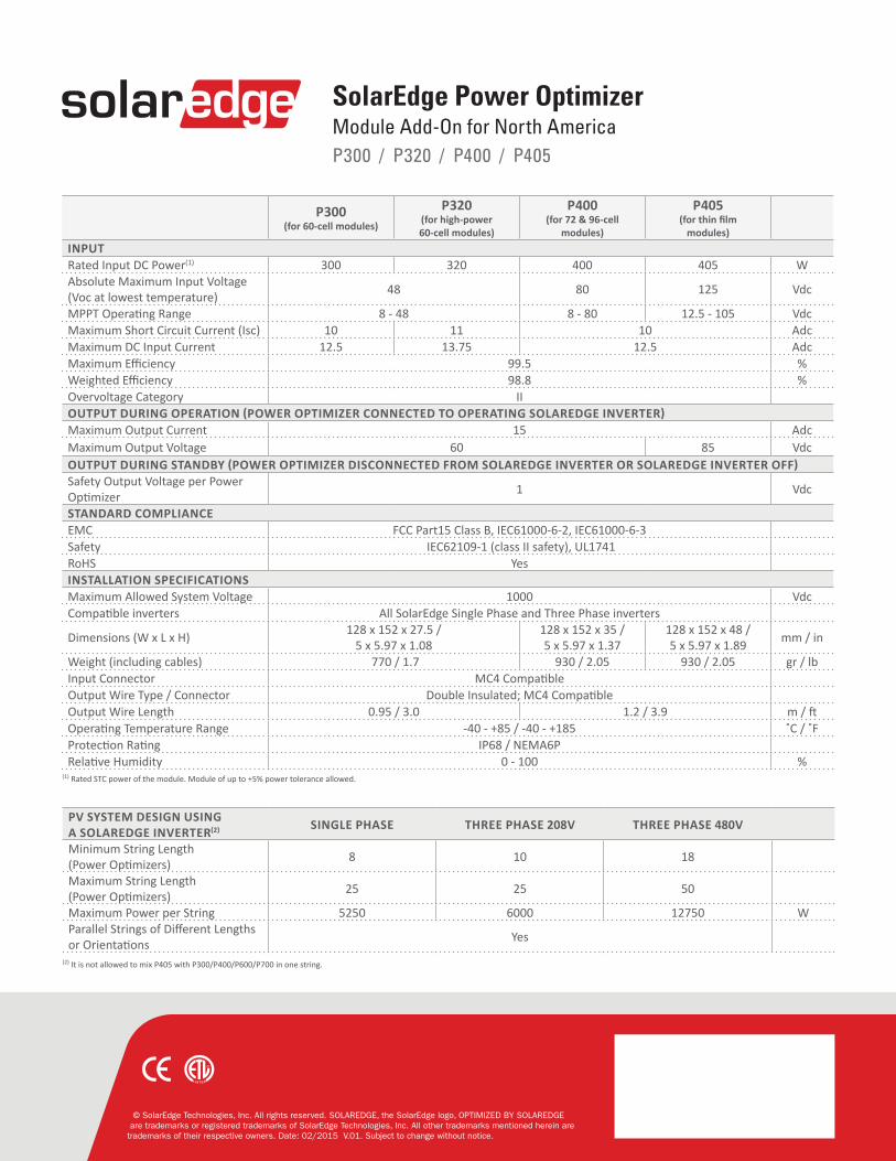
SolarEdge Power OptimizerModule Add-On For North AmericaP300 / P320 / P400 / P405
Up to 25% more energy Superiorefficiency(99.5%) Mitigatesalltypesofmodulemismatchlosses,frommanufacturingtolerancetopartialshading Flexiblesystemdesignformaximumspaceutilization Fastinstallationwithasinglebolt Nextgenerationmaintenancewithmodule-levelmonitoring Module-levelvoltageshutdownforinstallerandfirefightersafety
modules)INPUTRated Input DC Power(1) 300 320 400 405 WAbsolute Maximum Input Voltage (Vocatlowesttemperature) 48 80 125 Vdc
MPPTOperatingRange 8-48 8-80 12.5-105 VdcMaximumShortCircuitCurrent(Isc) 10 11 10 AdcMaximum DC Input Current 12.5 13.75 12.5 AdcMaximumEfficiency 99.5 %WeightedEfficiency 98.8 %OvervoltageCategory IIOUTPUT DURING OPERATION (POWER OPTIMIZER CONNECTED TO OPERATING SOLAREDGE INVERTER)Maximum Output Current 15 AdcMaximum Output Voltage 60 85 VdcOUTPUT DURING STANDBY (POWER OPTIMIZER DISCONNECTED FROM SOLAREDGE INVERTER OR SOLAREDGE INVERTER OFF)SafetyOutputVoltageperPowerOptimizer 1 Vdc
STANDARD COMPLIANCEEMC FCCPart15ClassB,IEC61000-6-2,IEC61000-6-3Safety IEC62109-1(classIIsafety),UL1741RoHS Yes INSTALLATION SPECIFICATIONS Maximum Allowed System Voltage 1000 VdcCompatibleinverters AllSolarEdgeSinglePhaseandThreePhaseinverters
Rapid Shutdown Kit - Installation and Configuration
(Single Phase Inverters)
This document describes how to install the rapid shutdown kit in the SolarEdge Safety Switch, and how to enable the rapid
shutdown feature in the inverter in order to provide the functionality described in the Rapid Shutdown clause of NEC2014
690.12 (1) through (4).
Kit Contents
Rapid shutdown cables
Micro-SD card and SD card adapter with firmware files (Note: DO NOT THROW AWAY THE CARD AND THE ADAPTER; keep
them for installation of other rapid shutdown kits)
Cable Installation
Perform this procedure before connecting the strings to the Safety Switch [Chapter 4: Connecting the AC and the Strings to the
Safety Switch in the SolarEdge Installation Guide].
1 Turn the inverter ON/OFF switch to OFF. If installing the kit in an inverter that is already operating, wait until the LCD indicates that the DC voltage is safe (<50V), or wait five minutes before continuing to the next step.
2 Turn the Safety Switch and the AC switch on the main circuit board to OFF.
WARNING!
If you cannot see the inverter panel, or if a malfunction is indicated on the LCD panel, wait five minutes for the input
capacitors of the inverter to discharge.
3 Loosen the four Allen screws on the front cover of the Safety Switch, and open the cover.
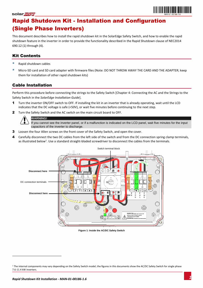
4 Carefully disconnect the two DC cables from the left side of the switch and from the DC connection spring clamp terminals, as illustrated below1. Use a standard straight-bladed screwdriver to disconnect the cables from the terminals.
Figure 1: Inside the AC/DC Safety Switch
1 The internal components may vary depending on the Safety Switch model; the figures in this documents show the AC/DC Safety Switch for single phase 7.6-11.4 kW inverters.
DC connection terminals
Disconnect here
Disconnect here
Switch terminal block
Rapid Shutdown Kit - Installation and Configuration (Single Phase Inverters)
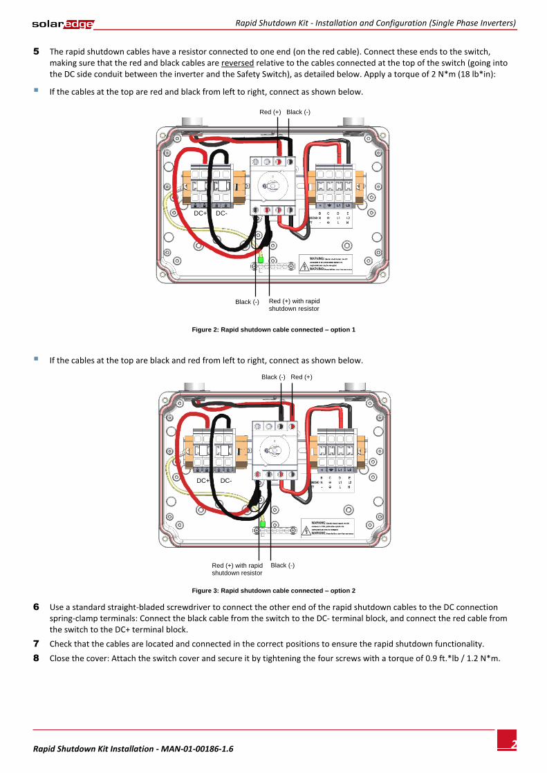
5 The rapid shutdown cables have a resistor connected to one end (on the red cable). Connect these ends to the switch, making sure that the red and black cables are reversed relative to the cables connected at the top of the switch (going into the DC side conduit between the inverter and the Safety Switch), as detailed below. Apply a torque of 2 N*m (18 lb*in):
If the cables at the top are red and black from left to right, connect as shown below.
6 Use a standard straight-bladed screwdriver to connect the other end of the rapid shutdown cables to the DC connection spring-clamp terminals: Connect the black cable from the switch to the DC- terminal block, and connect the red cable from the switch to the DC+ terminal block.
7 Check that the cables are located and connected in the correct positions to ensure the rapid shutdown functionality.
8 Close the cover: Attach the switch cover and secure it by tightening the four screws with a torque of 0.9 ft.*lb / 1.2 N*m.
Red (+) Black (-)
Black (-)
DC+ DC-
Red (+) with rapid shutdown resistor
Black (-) Red (+)
Black (-)
Red (+) with rapid shutdown resistor
DC+ DC-
Rapid Shutdown Kit - Installation and Configuration (Single Phase Inverters)
Perform this procedure after activating the inverter [Step 1 in Chapter 5: Commissioning the Installation of the SolarEdge
Installation Guide], and before pairing (Step 2 in Chapter 5 of the SolarEdge Installation Guide).
To use the rapid shutdown feature, the inverter communication board firmware (CPU) must be:
Version 2.0700 or higher, if the CPU version is 2.0xxx
Version 3.0700 or higher, if the CPU version is 3.0xxx
► To check the inverter CPU version:
1 Verify that the inverter has been activated using the activation card supplied with the inverter.
2 Press the LCD light button short presses until the screen below is reached.
I D : # # # # # # # # # #
D S P 1 / 2 : x . x x x x / x . x x x x
C P U : 0 0 0 2 . 0 7 0 0
C o u n t r y : X X X X X
3 Check the CPU version number. If lower than 2.0700, upgrade the inverter software as described below; otherwise proceed to “Power Optimizer Pairing”.
► To upgrade the inverter software:
Use the supplied SD card adapter or the micro-SD card, which can be removed from the adapter, according to the activation
card slot on your inverter communication board, labeled .
1 Verity that the AC breaker connected to the inverter is OFF.
2 Open the inverter cover’s six Allen screws and carefully pull the cover horizontally before lowering it, as described in its manual.
3 Insert the card into the card slot on the communication board. If the communication board has an SD card slot, use the supplied SD card adapter. If there is a micro-SD card slot, remove the micro-SD card from the adaptor and insert it.
4 Close the inverter cover and turn the AC on. If upgrade is required (as described above), it starts automatically.
5 Wait for the message "Done" to be displayed on the LCD.
6 Verify the correct version as described above.
7 Remove the card from the inverter and keep it for additional kit installations.
Power Optimizer Pairing
Pairing at this stage will reprogram the power optimizers to perform rapid shutdown.
1 Verify that the ON/OFF switch at the bottom of the inverter is OFF.
2 Turn ON the AC breaker and the Safety Switch.
3 Perform Pairing as described in Step 2: Pairing, of Chapter 5: Commissioning of the SolarEdge Installation Guide.
Enabling Rapid Shutdown
There is an option in setup mode to enable the functionality of rapid shutdown.
1 Verify that the ON/OFF switch at the bottom of the inverter is ON.
2 Enter Setup mode by pressing and holding the LCD light button.
3 Select Maintenance Optimizer Conf. Set Rapid Shutdown.
NOTE:
Whenever replacing, removing or adding a component in the string, perform Pairing and rapid shutdown setting.
Troubleshooting
If the inverter does not enter production mode and the LCD displays Night Mode, the connection order of the rapid shutdown
cables may be incorrect. Recheck the cables and make sure that the rapid shutdown cables connected to the bottom of the
switch are reversed relative to the cables connected at the top of the switch (see Figure 2 and Figure 3).
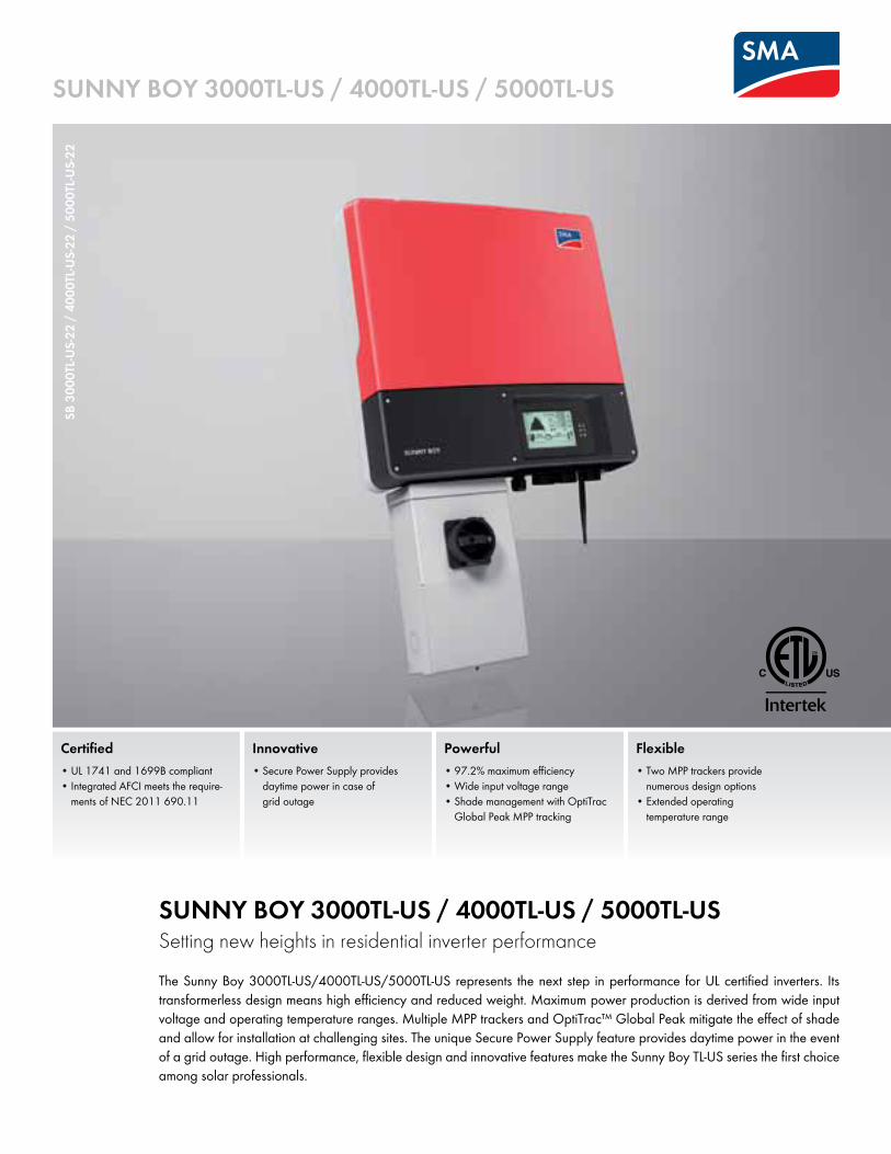
SUNNY BOY 3000TL-US / 4000TL-US / 5000TL-USSetting new heights in residential inverter performanceThe Sunny Boy 3000TL-US/4000TL-US/5000TL-US represents the next step in performance for UL certified inverters. Its transformerless design means high efficiency and reduced weight. Maximum power production is derived from wide input voltage and operating temperature ranges. Multiple MPP trackers and OptiTrac™ Global Peak mitigate the effect of shade and allow for installation at challenging sites. The unique Secure Power Supply feature provides daytime power in the event of a grid outage. High performance, flexible design and innovative features make the Sunny Boy TL-US series the first choice among solar professionals.
Certified• UL 1741 and 1699B compliant• Integrated AFCI meets the require-
ments of NEC 2011 690.11
Powerful• 97.2% maximum efficiency• Wide input voltage range• Shade management with OptiTrac
Global Peak MPP tracking
Flexible• Two MPP trackers provide
numerous design options• Extended operating
temperature range
Innovative• Secure Power Supply provides
daytime power in case of grid outage
SUNNY BOY 3000TL-US / 4000TL-US / 5000TL-US
SB 3
000T
L-US-
22 /
4000
TL-U
S-22
/ 50
00TL
-US-
22
SMA America, LLCToll Free +1 888 4 SMA USAwww.SMA-America.com
SB34
5TLU
SEXD
S-DU
S131
625
SMA
and
Sunn
y Boy
are
regi
stere
d tra
dema
rks o
f SM
A So
lar T
echn
olog
y AG
. Tex
t and
figure
s com
ply w
ith th
e sta
te of
the
art a
pplic
able
when
prin
ting.
Sub
ject to
tech
nical
chan
ges.
We
acce
pt n
o lia
bility
for t
ypog
raph
ical a
nd o
ther e
rrors.
Prin
ted o
n chlo
rine-
free
pape
r.
Speedwire/Webconnect interface SWDM-US-10
RS485 interface DM-485CB-US-10
Accessories
Fan kit FANKIT02-10
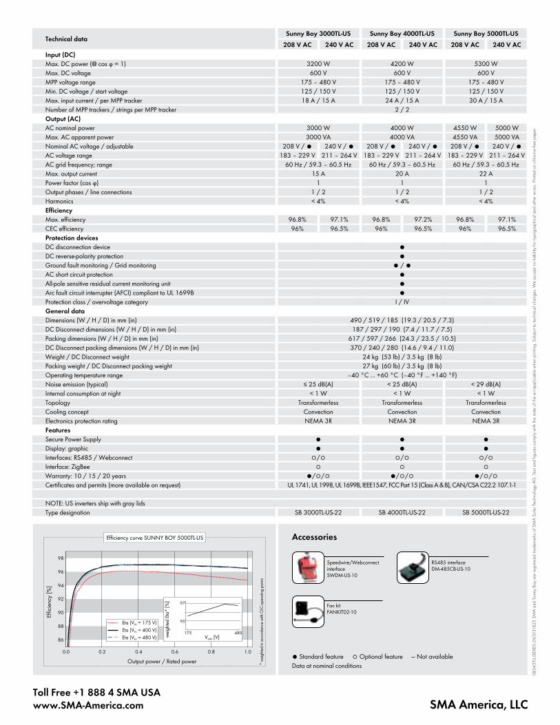
Technical dataSunny Boy 3000TL-US Sunny Boy 4000TL-US Sunny Boy 5000TL-US
208 V AC 240 V AC 208 V AC 240 V AC 208 V AC 240 V ACInput (DC)Max. DC power (@ cos ϕ = 1) 3200 W 4200 W 5300 WMax. DC voltage 600 V 600 V 600 VMPP voltage range 175 – 480 V 175 – 480 V 175 – 480 VMin. DC voltage / start voltage 125 / 150 V 125 / 150 V 125 / 150 VMax. input current / per MPP tracker 18 A / 15 A 24 A / 15 A 30 A / 15 ANumber of MPP trackers / strings per MPP tracker 2 / 2Output (AC)AC nominal power 3000 W 4000 W 4550 W 5000 WMax. AC apparent power 3000 VA 4000 VA 4550 VA 5000 VANominal AC voltage / adjustable 208 V / ● 240 V / ● 208 V / ● 240 V / ● 208 V / ● 240 V / ●AC voltage range 183 – 229 V 211 – 264 V 183 – 229 V 211 – 264 V 183 – 229 V 211 – 264 VAC grid frequency; range 60 Hz / 59.3 – 60.5 Hz 60 Hz / 59.3 – 60.5 Hz 60 Hz / 59.3 – 60.5 HzMax. output current 15 A 20 A 22 APower factor (cos ϕ) 1 1 1Output phases / line connections 1 / 2 1 / 2 1 / 2Harmonics < 4% < 4% < 4%EfficiencyMax. efficiency 96.8% 97.1% 96.8% 97.2% 96.8% 97.1%CEC efficiency 96% 96.5% 96% 96.5% 96% 96.5%Protection devicesDC disconnection device ●DC reverse-polarity protection ●Ground fault monitoring / Grid monitoring ● / ●AC short circuit protection ●All-pole sensitive residual current monitoring unit ●Arc fault circuit interrupter (AFCI) compliant to UL 1699B ●Protection class / overvoltage category I / IVGeneral dataDimensions (W / H / D) in mm (in) 490 / 519 / 185 (19.3 / 20.5 / 7.3)DC Disconnect dimensions (W / H / D) in mm (in) 187 / 297 / 190 (7.4 / 11.7 / 7.5)Packing dimensions (W / H / D) in mm (in) 617 / 597 / 266 (24.3 / 23.5 / 10.5)DC Disconnect packing dimensions (W / H / D) in mm (in) 370 / 240 / 280 (14.6 / 9.4 / 11.0)Weight / DC Disconnect weight 24 kg (53 lb) / 3.5 kg (8 lb)Packing weight / DC Disconnect packing weight 27 kg (60 lb) / 3.5 kg (8 lb)Operating temperature range –40 °C ... +60 °C (–40 °F ... +140 °F)Noise emission (typical) ≤ 25 dB(A) < 25 dB(A) < 29 dB(A)Internal consumption at night < 1 W < 1 W < 1 WTopology Transformerless Transformerless TransformerlessCooling concept Convection Convection ConvectionElectronics protection rating NEMA 3R NEMA 3R NEMA 3RFeatures Secure Power Supply ● ● ●Display: graphic ● ● ●Interfaces: RS485 / Webconnect ○/○ ○/○ ○/○Interface: ZigBee ○ ○ ○Warranty: 10 / 15 / 20 years ●/○/○ ●/○/○ ●/○/○Certificates and permits (more available on request) UL 1741, UL 1998, UL 1699B, IEEE1547, FCC Part 15 (Class A & B), CAN/CSA C22.2 107.1-1
NOTE: US inverters ship with gray lidsType designation SB 3000TL-US-22 SB 4000TL-US-22 SB 5000TL-US-22
● Standard feature ○ Optional feature — Not availableData at nominal conditions
RSB-
2S-U
S-10
& R
SC-1
X-US
-10
Reliable• Optimal system reliability with
hybrid switches for disconnecting • Automatic self-test upon startup to
ensure functionality
Perfect alignment• Engineered for Sunny Boy-US and
Sunny Boy TL-US inverter lines with multiple MPP tracking channels
• Compatible with Secure Power Supply
Code compliant•UL-Certifiedandcompliant
with 2014 NEC 690.12 Rapid Shutdown
• No interference with AFCI function of Sunny Boy inverters
Cost effective• Incorporated junction box reduces
equipment and speeds installation time• Pre-wired MC4 connectors and
snap terminals reduce materials and installation time
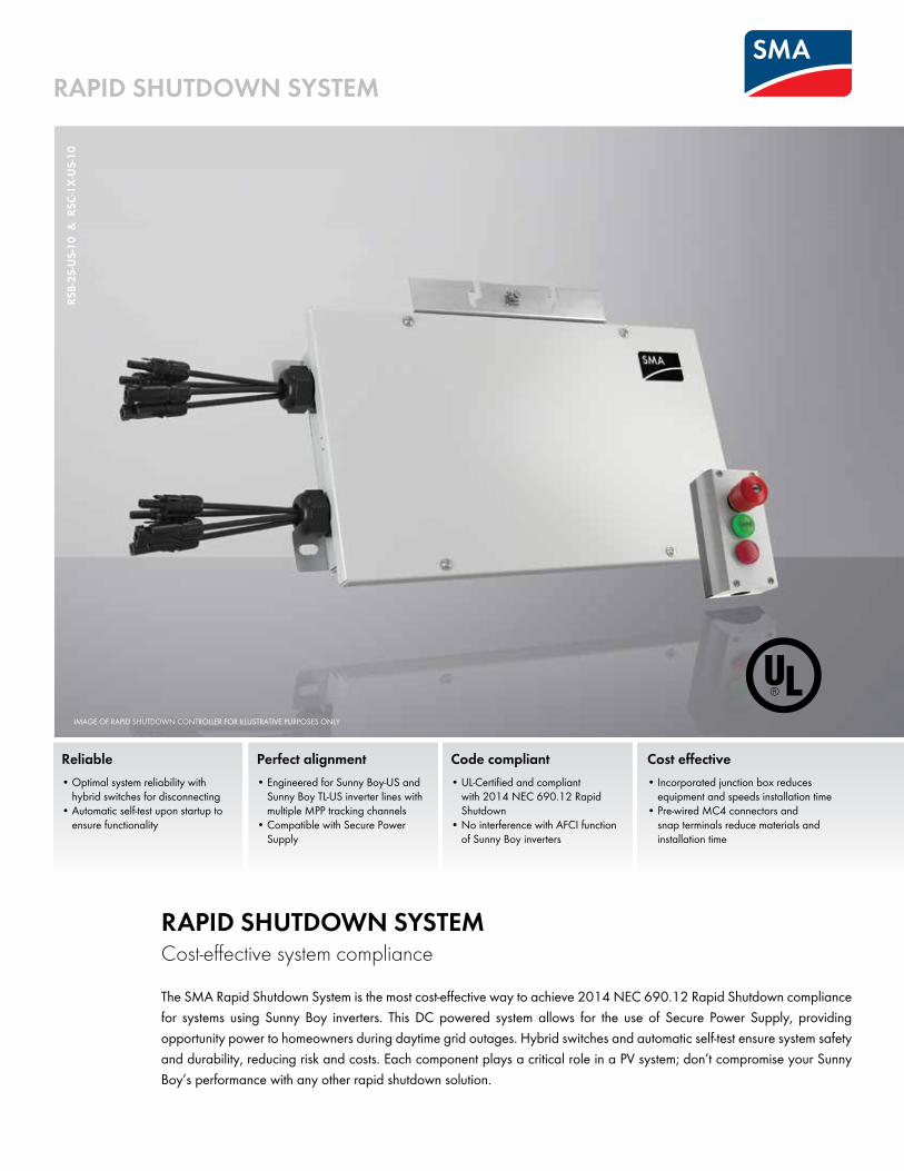
RAPID SHUTDOWN SYSTEMCost-effective system compliance
The SMA Rapid Shutdown System is the most cost-effective way to achieve 2014 NEC 690.12 Rapid Shutdown compliance for systems using Sunny Boy inverters. This DC powered system allows for the use of Secure Power Supply, providing opportunity power to homeowners during daytime grid outages. Hybrid switches and automatic self-test ensure system safety and durability, reducing risk and costs. Each component plays a critical role in a PV system; don’t compromise your Sunny Boy’s performance with any other rapid shutdown solution.
RAPID SHUTDOWN SYSTEM
IMAGE OF RAPID SHUTDOWN CONTROLLER FOR ILLUSTRATIVE PURPOSES ONLY
SMA America, LLCToll Free +1 888 4 SMA USAwww.SMA-America.com
RSDB
OX-
DUS1
6172
4 S
MA
and
Sunn
y Boy
are
regi
stere
d tra
dema
rks o
f SM
A So
lar T
echn
olog
y AG
. Prin
ted o
n FSC
-certi
fied
pape
r. All p
rodu
cts a
nd se
rvice
s des
crib
ed a
s well
as t
echn
ical d
ata
are s
ubjec
t to ch
ange
, eve
n for
reas
ons o
f cou
ntry-s
pecif
ic de
viatio
ns, a
t any
time w
ithou
t not
ice. S
MA
assu
mes n
o lia
bility
for e
rrors
or o
miss
ions
. For
curre
nt inf
orma
tion,
see w
ww.
SMA-
Sola
r.com
.
Technical data Rapid Shutdown Box
General dataMaximum input voltage 600 V DCMinimum input voltage 110 V DCNumber of DC inputs 4 strings, 2 in parallel per channelDC operating current per channel 20 A DCMaximum channel short circuit current per channel 36 A DCIntegrated power supply DC powered by PV array (max. 5W)Ambient temperature range -40°C to +75°CDimensions without pre-wired cables (W x H x D) 542 x 340 x 75 mm / 21.3 x 13.4 x 2.95 inWeight 3.8 kg / 8.4 lbDC input Cable whips with MC4 connectorsWire size DC outputs AWG 12 to AWG 6Wire size control wires AWG 18 to 16Wire size grounding AWG 10 to AWG 6Enclosure rating Type 4XEnclosurefinish AluminumConduit size (home run) 3/4 inch conduitConduit size (control wires) 2 x 1/2 inch for daisy chain wiringWarranty 10 yearsCompliance NEC 2014, article 690.12Safetylistingandcertification UL 1741
Type designation RSB-2S-US-10
Technical data Rapid Shutdown Controller
General dataStatus indicator 2 LEDsDimensions (W x H x D) 80 x 153 x 104 mm / 3.15 x 6.02 x 4.1 inWeight 0.3 kg / 0.72 lbAmbient temperature range -25°C to +70°CEnclosure rating Type 4XEnclosurefinish Polycarbonate
Type designation RSC-1X-US-10
First Responder SafetyLED indicator lights ensure safe operation for first responders.
Rapid Shutdown BoxSlim design fits under PV modules.
Rapid Shutdown ControllerMounting in close proximity to the inverter is not required.
Secure Power Supply (SPS)Rapid Shutdown System ensures SPS functionality byusing PV array’s DC power.
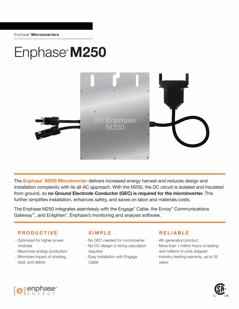
Enphase® Microinverters
®
The Enphase® M250 Microinverter delivers increased energy harvest and reduces design and installation complexity with its all-AC approach. With the M250, the DC circuit is isolated and insulated from ground, so no Ground Electrode Conductor (GEC) is required for the microinverter. This further simplifies installation, enhances safety, and saves on labor and materials costs.
The Enphase M250 integrates seamlessly with the Engage® Cable, the Envoy® Communications GatewayTM, and Enlighten®, Enphase’s monitoring and analysis software.
P R O D U C T I V E S I M P L E R E L I A B L E- Optimized for higher-power
modules- Maximizes energy production- Minimizes impact of shading,
dust, and debris
- No GEC needed for microinverter- No DC design or string calculation
required- Easy installation with Engage
Cable
- 4th-generation product- More than 1 million hours of testing
and millions of units shipped- Industry-leading warranty, up to 25
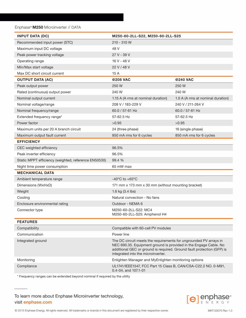
INPUT DATA (DC) M250-60-2LL-S22, M250-60-2LL-S25Recommended input power (STC) 210 - 310 WMaximum input DC voltage 48 VPeak power tracking voltage 27 V - 39 VOperating range 16 V - 48 VMin/Max start voltage 22 V / 48 VMax DC short circuit current 15 AOUTPUT DATA (AC) @208 VAC @240 VACPeak output power 250 W 250 WRated (continuous) output power 240 W 240 WNominal output current 1.15 A (A rms at nominal duration) 1.0 A (A rms at nominal duration)Nominal voltage/range 208 V / 183-229 V 240 V / 211-264 VNominal frequency/range 60.0 / 57-61 Hz 60.0 / 57-61 HzExtended frequency range* 57-62.5 Hz 57-62.5 HzPower factor >0.95 >0.95Maximum units per 20 A branch circuit 24 (three phase) 16 (single phase)Maximum output fault current 850 mA rms for 6 cycles 850 mA rms for 6 cyclesEFFICIENCYCEC weighted efficiency 96.5%Peak inverter efficiency 96.5%Static MPPT efficiency (weighted, reference EN50530) 99.4 %Night time power consumption 65 mW maxMECHANICAL DATAAmbient temperature range -40ºC to +65ºCDimensions (WxHxD) 171 mm x 173 mm x 30 mm (without mounting bracket)Weight 1.6 kg (3.4 lbs)Cooling Natural convection - No fansEnclosure environmental rating Outdoor - NEMA 6Connector type M250-60-2LL-S22: MC4
M250-60-2LL-S25: Amphenol H4
FEATURESCompatibility Compatible with 60-cell PV modulesCommunication Power lineIntegrated ground The DC circuit meets the requirements for ungrounded PV arrays in
NEC 690.35. Equipment ground is provided in the Engage Cable. No additional GEC or ground is required. Ground fault protection (GFP) is integrated into the microinverter.
Monitoring Enlighten Manager and MyEnlighten monitoring optionsCompliance UL1741/IEEE1547, FCC Part 15 Class B, CAN/CSA-C22.2 NO. 0-M91,
0.4-04, and 107.1-01* Frequency ranges can be extended beyond nominal if required by the utility
MKT-00070 Rev 1.0
solarworld.com
SW 280 MONO
Designed to withstand heavy accumulations of snow and ice
Every component is tested to meet 3 times IEC requirements
Sunmodule Plus:Positive performance tolerance
25-year linear performance warranty and 10-year product warranty
Glass with anti-reflective coating
-0/+5 Wp
Anti-ReflectiveCoating
TUV Power controlled: Lowest measuring tolerance in industry
World-class qualityFully-automated production lines and seamless monitoring of the process and mate-rial ensure the quality that the company sets as its benchmark for its sites worldwide.
SolarWorld Plus-SortingPlus-Sorting guarantees highest system efficiency. SolarWorld only delivers modules that have greater than or equal to the nameplate rated power.
25-year linear performance guarantee and extension of product warranty to 10 yearsSolarWorld guarantees a maximum performance digression of 0.7% p.a. in the course of 25 years, a significant added value compared to the two-phase warranties com-mon in the industry. In addition, SolarWorld is offering a product warranty, which has been extended to 10 years.*
*in accordance with the applicable SolarWorld Limited Warranty at purchase.www.solarworld.com/warranty
geprüteSicherheit
SW 280 MONO
SW-01-6006US 08-2014
THERMAL CHARACTERISTICS
NOCT 46 °C
TC Isc 0.04 %/°CTC Voc -0.30 %/°CTC Pmpp -0.41 %/°COperating temperature -40°C to 85°C
PERFORMANCE AT 800 W/m², NOCT, AM 1.5
Maximum power Pmax 209.2 Wp
Open circuit voltage Voc 36.1 VMaximum power point voltage Vmpp 28.5 VShort circuit current Isc 7.85 AMaximum power point current Impp 7.33 AMinor reduction in efficiency under partial load conditions at 25°C: at 200 W/m², 100% (+/-2%) of the STC efficiency (1000 W/m²) is achieved.
COMPONENT MATERIALS
Cells per module 60
Cell type Mono crystallineCell dimensions 6.14 in x 6.14 in (156 mm x 156 mm)Front Tempered glass (EN 12150)Frame Clear anodized aluminumWeight 39.5 lbs (17.9 kg)
37.44 (951)
39.37 (1000)
ADDITIONAL DATA
Power sorting1 -0 Wp / +5 Wp
J-Box IP65Module leads PV wire per UL4703 with H4 connectors Module type (UL 1703) 1Glass Low iron tempered with ARC
SYSTEM INTEGRATION PARAMETERS
Maximum system voltage SC II / NEC 1000 V
Maximum reverse current 16 ANumber of bypass diodes 3
Design Loads* Two rail system 113 psf downward64 psf upward
Design Loads* Three rail system 170 psf downward71 psf upward
* Please refer to the Sunmodule installation instructions for the details associated with these load cases.
PERFORMANCE UNDER STANDARD TEST CONDITIONS (STC)*
1) Measuring tolerance (Pmax ) traceable to TUV Rheinland: +/- 2% (TUV Power Controlled).
Maximum power Pmax 280 Wp
Open circuit voltage Voc 39.5 VMaximum power point voltage Vmpp 31.2 VShort circuit current Isc 9.71 AMaximum power point current Impp 9.07 AModule efficiency ƞm 16.70 %
*STC: 1000 W/m², 25°C, AM 1.5
All units provided are imperial. SI units provided in parentheses. SolarWorld AG reserves the right to make specification changes without notice.
Mod
ule
curr
ent [
A]
Module voltage [V]
1000 W/m²
800 W/m²
600 W/m²
400 W/m²
200 W/m²
100 W/m²
ISC
VOC
snapnrack.com
Solar Mounting Solutions
Resources snapnrack.com/resources Design configure.snapnrack.com Where to Buy snapnrack.com/buy
Series 100 Residential Roof Mount System
The SnapNrack Series 100 UL Roof Mount System is an efficient, visually appealing, photovoltaic (PV) module installation system. Series 100 UL is listed to the UL 2703 for grounding/bonding and fire classification. The System’s components provide an adequate bonding path which has eliminated the need for grounding lugs and wash-ers at each module, and bonding jumpers between splices. In addition to grounding and bonding, the roof mount system, Series 100 UL, is Class A Fire Rated when in-stalled with Type I and Type II Modules. SnapNrack’s UL 2703 Certification and Com-pliance ensures that SnapNrack installers can continue to provide the best in class installations in quality, safety and efficiency.
ò Appealing design with built-in aesthetics
ò No grounding lugs required for modules
ò All bonding hardware is fully integrated into the components
ò Rail splices bond rails together, no rail jump-ers required
ò Proprietary SnapNrack grounding lug snaps in the rail channel
ò No drilling of rail or reaching for other tools required
� ¢ � S ý £ � � � S � � ¤ � ý ¿ � » ½ É � � � ¿ à » º ¼ ¿ À ¾ � à À � ¹ ¸ � ¸ ¸ ¹ º » ¸ ¼ ½ ¾ ¿ À Á  à » Ä Å À Æ » ½ ¾ � � È Ä ¸ � � È Ë Ì Ë Í Î Ï Ï Ð ÑÒ � � � Ó � � �Ô ÕÖ×ØÙÚ ØÖÛÜ ÖÝÙÞ ßàáâ � � � ç ç è ç ç é ç ê è ç ê é ç ë è ç ë é ç ì è ç ì é ç é è ç é é ç í è ç î è ç ï è ç ð è� � ç é ó é ç í ó ð ç ï ó ì ê è ó è ê ç ó í ê ë ó ë ê é ó ç ê í ó ð ê ï ó ï ë è ó î ë ê ó ï ë î ó è ì ç ó é ì í ó êô õ ô ö ÷ � ú û ÷ û ú ý ÷ û ú � ÷ þ ú � ÷ � ú ý ÷ ø ù ú ù ÷ ø ù ú þ ÷ ø ø ú � ÷ ø ü ú ÿ ÷ ø ý ú ü ÷ ø ÿ ú ø ÷ ø � ú � ÷ ø û ú þ ÷ ø � ú �è è ø ü ù ø ü ù ø ü ù ø ü ù ø ü ù ø ü ù ø ø � ø ø ø ø ù � ø ù ü � þ � ø þ � þ ùç è ï ø ø ü ø ø ø ø ø ù ø ù � ø ù þ ø ù û ø ù � ø ù ÿ ø ù ý ø ù ü � þ � ø þ � þ ùê è ç é þ � þ � þ � þ � þ � þ � þ þ þ þ þ û þ û þ � þ � þ ý þ ùë è ê ë û � û � û � û � û � û � û � û � û � û � û � û � û ÿ û ýì è ë ç � � � � � � � � � � � � � � � � � � � � � � � � � � � �é è ë ð � ù � ù � ù � ù � ù � ù � ù � ù � ù � ù � ù � ù � ù � ùí è ì í � � � � � � � � � � � � � � � � � � � � � � � � � � � �î è é ì � ø � ø � ø � ø � ø � ø � ø � ø � ø � ø � ø � ø � ø � øï è í ê ÿ þ ÿ þ ÿ þ ÿ þ ÿ þ ÿ þ ÿ þ ÿ þ ÿ þ ÿ þ ÿ þ ÿ þ ÿ þ ÿ þç è è î î ÿ ý ÿ ý ÿ ý ÿ ý ÿ ý ÿ ý ÿ ý ÿ ý ÿ ý ÿ ý ÿ ý ÿ ý ÿ ý ÿ ýç ê è ð ê ÿ ù ÿ ù ÿ ù ÿ ù ÿ ù ÿ ù ÿ ù ÿ ù ÿ ù ÿ ù ÿ ù ÿ ù ÿ ù ÿ ù� ¢ � S ý £ � � � S � � ¤ � ý ¿ � » ½ É � � � ¿ à » º ¼ ¿ À ¾ � à À � ¹ ¸ � ¸ ¸ ¹ º » ¸ ¼ ½ ¾ ¿ À Á  à » Ä Å À Æ » ½ ¾ � � È Ä ¸ � Ç È Ë Ì Ë Í Î Ï Ï Ð ÑÒ � � � Ó � � �
Ô ÕÖ×ØÙÚ ØÖÛÜ ÖÝÙÞ ßàáâ � � � ç ç è ç ç é ç ê è ç ê é ç ë è ç ë é ç ì è ç ì é ç é è ç é é ç í è ç î è ç ï è ç ð è� � ç é ó é ç í ó ð ç ï ó ì ê è ó è ê ç ó í ê ë ó ë ê é ó ç ê í ó ð ê ï ó ï ë è ó î ë ê ó ï ë î ó è ì ç ó é ì í ó êô õ ô ö ÷ � ú ý ÷ � ú � ÷ û ú � ÷ þ ú ü ÷ þ ú � ÷ � ú � ÷ ø ù ú ý ÷ ø ø ú ù ÷ ø ø ú þ ÷ ø ü ú � ÷ ø ý ú ÿ ÷ ø � ú ü ÷ ø û ú ù ÷ ø þ ú �è è ø ü ù ø ü ù ø ü ù ø ü ù ø ø þ ø ø � ø ø ý ø ø ù ø ù û ø ù � ø ù ø � ÿ þ þ þ üç è ï ø ù � ø ù � ø ù ÿ ø ù ü ø ù ø ø ù ù � þ � û � � � ÿ � ý � ù þ þ þ üê è ç é þ � þ þ þ û þ û þ � þ � þ ÿ þ ý þ ü þ ü þ ø û � û û û �ë è ê ë û � û � û � û � û � û � û � û ÿ û ÿ û ý û ü û ø û ù � �ì è ë ç � � � � � � � � � � � � � � � � � � � � � � � � � ÿ � ýé è ë ð � ù � ù � ù � ù � ù � ù � ù � ù � ù � ù � ù � ù � ù � �í è ì í � � � � � � � � � � � � � � � � � � � � � � � � � � � �î è é ì � ø � ø � ø � ø � ø � ø � ø � ø � ø � ø � ø � ø � ø � øï è í ê ÿ þ ÿ þ ÿ þ ÿ þ ÿ þ ÿ þ ÿ þ ÿ þ ÿ þ ÿ þ ÿ þ ÿ þ ÿ þ ÿ þç è è î î ÿ ý ÿ ý ÿ ý ÿ ý ÿ ý ÿ ý ÿ ý ÿ ý ÿ ý ÿ ý ÿ ý ÿ ý ÿ ý ÿ ýç ê è ð ê ÿ ù ÿ ù ÿ ù ÿ ù ÿ ù ÿ ù ÿ ù ÿ ù ÿ ù ÿ ù ÿ ù ÿ ù ÿ ù ÿ ù