Page 1
8/6/2019 Example the Admittance Matrix
http://slidepdf.com/reader/full/example-the-admittance-matrix 1/5
3/1/2005 Example The Admittance Matrix.doc 1/5
Jim Stiles The Univ. of Kansas Dept. of EECS
0Z β ,
I 1
2R 0Z β ,
I 2
R +
V 2 -
+
V 1 -
Example: Evaluating the
Admittance MatrixConsider the following two-port device:
Let’s determine the admittance matrix of this device!
Step 1: Place a short at port 2.
0Z β ,
I 1
2R
I 2
R +
V 2 =0
-
+
V 1
-
Page 2
8/6/2019 Example the Admittance Matrix
http://slidepdf.com/reader/full/example-the-admittance-matrix 2/5
3/1/2005 Example The Admittance Matrix.doc 2/5
Jim Stiles The Univ. of Kansas Dept. of EECS
Step 2: Determine currents I 1 and I 2 .
Note that after the short was placed at port 2, both
resistors are in parallel, with a potential V 2 across each.
The current I 1 is thus simply the sum of the two currents
through each resistor:
11 11
3
2 2
V V V I
R R R = + =
The current I 2 is simply the opposite of the current through
R: 1
2
V I
R = −
Step 3: Determine trans-admittance Y 11 and Y 21 .
1
11 1
3
2
I Y
V R = =
221
1
1I Y
V R = = −
Note that 21Y is real—but negative!
This is still a valid physical result, although you will find that
the diagonal terms of an impedance or admittance matrix
(e.g., 22Y , 11Z , 44Y ) will always have a real component that is
positive.
Page 3
8/6/2019 Example the Admittance Matrix
http://slidepdf.com/reader/full/example-the-admittance-matrix 3/5
3/1/2005 Example The Admittance Matrix.doc 3/5
Jim Stiles The Univ. of Kansas Dept. of EECS
To find the other two trans-admittance parameters, we must
move the short and then repeat each of our previous steps!
Step 1: Place a short at port 1.
Step 2: Determine currents I 1 and I 2 .
Note that after a short was placed at port 1, resistor 2R has
zero voltage across it—and thus zero current through it!
Likewise, from KVL we find that the voltage across resistor R
is equal to V 2 .
Finally, we see from KCL that 1 2I I = .
The current I 2 thus:
22 V I R =
and thus:
21
V I
R = −
I 1
2R 0Z β ,
I 2
R +
V 1 =0
-
+
V 2
-
Page 4
8/6/2019 Example the Admittance Matrix
http://slidepdf.com/reader/full/example-the-admittance-matrix 4/5
3/1/2005 Example The Admittance Matrix.doc 4/5
Jim Stiles The Univ. of Kansas Dept. of EECS
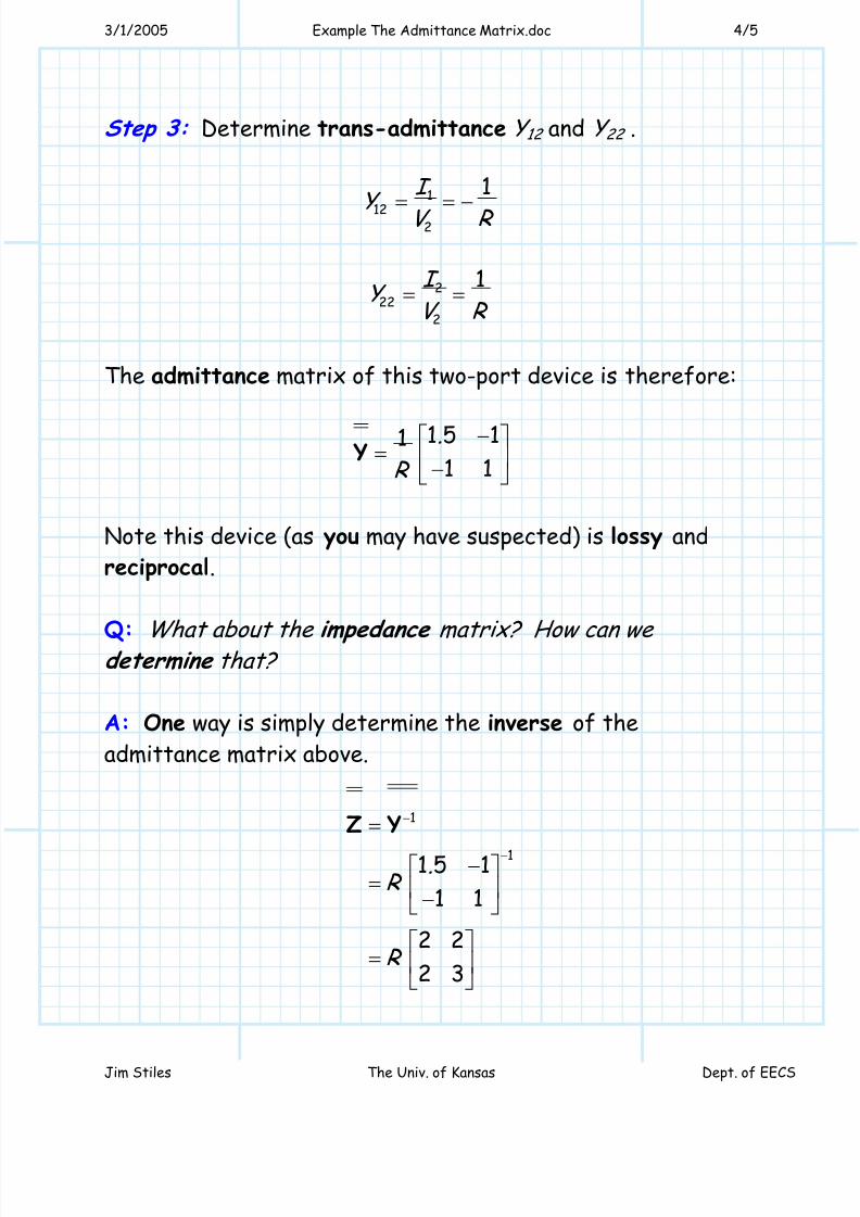
Step 3: Determine trans-admittance Y 12 and Y 22 .
1
122
1I
Y V R = = −
222
2
1I Y
V R = =
The admittance matrix of this two-port device is therefore:
1 5 111 1
.
R
−⎡ ⎤= ⎢ ⎥−⎣ ⎦
Y
Note this device (as you may have suspected) is lossy and
reciprocal.
Q: What about the impedance matrix? How can we determine that?
A: One way is simply determine the inverse of the
admittance matrix above.
1
11 5 1
1 1
2 2
2 3
.R
R
−
−
=
−⎡ ⎤= ⎢ ⎥−⎣ ⎦
⎡ ⎤= ⎢ ⎥
⎣ ⎦
Z Y
Page 5
8/6/2019 Example the Admittance Matrix
http://slidepdf.com/reader/full/example-the-admittance-matrix 5/5
3/1/2005 Example The Admittance Matrix.doc 5/5
Jim Stiles The Univ. of Kansas Dept. of EECS
A: Another way to determine the impedance matrix is simply
to apply the definition of trans-impedance to directly
determine the elements of the impedance matrix—similar to
how we just determined the admittance matrix!
Specifically, follow these steps:
Step 1: Place an open at port 2 (or 1)
Step 2: Determine voltages V 1 and V 2 .
Step 3: Determine trans-impedance Z 11 and Z 21 (or Z 12 and
Z 22 ).
Try this procedure on the circuit of this example, and makesure you get the same result for Z as we determined on the
previous page (from matrix inversion)—after all, you want to
do well on my long, scary, evil exam!
Q: But I don’t know how to
invert a matrix! How can I
ossibly pass one of your
long, scary, evil exams?


![Effect of Distribution Generators on Stability in a ... · sient [6] considering the bus impedance matrix which is the inverse of the bus admittance matrix. Stability analysis is](https://static.documents.pub/doc/80x56/5eac72864d784927f130bdb7/effect-of-distribution-generators-on-stability-in-a-sient-6-considering-the.jpg)


