Name: ________________________ Class: ___________________ Date: __________ ID: A 1 MECH 1500 Quiz 4 Review True/False Indicate whether the statement is true or false. ____ 1. For the timer relay contact shown, when the relay coil is energized, there is a time delay before the contact closes. ____ 2. For the timer relay contact shown, when the relay coil is de-energized, there is a time delay before the contact opens. ____ 3. For the timer relay contact shown, when the relay coil is de-energized, there is a time delay before the contact closes. ____ 4. For the timer relay contact shown, when the relay coil is energized, there is a time delay before the contact opens. ____ 5. PLC timers are input instructions that provide the same functions as mechanical timing relays. ____ 6. Timer instructions are found on all PLCs manufactured today. ____ 7. The retentive timer reset (RES) instruction is always given the same address as the timer it resets. ____ 8. An alarm is to be switched on whenever a piping system has sustained a cumulative overpressure of 60 s. The most directly applicable timer to use would be the on-delay nonretentive timer. ____ 9. A lamp is to be switched off 10 s after a switch has been switched from it's on to off position. The most directly applicable timer to use would be the off-delay nonretentive timer.
Transcript
Name: ________________________ Class: ___________________ Date: __________ ID: A
1
MECH 1500 Quiz 4 Review
True/FalseIndicate whether the statement is true or false.
____ 1. For the timer relay contact shown, when the relay coil is energized, there is a time delay
before the contact closes.
____ 2. For the timer relay contact shown, when the relay coil is de-energized, there is a time delay before the
contact opens.
____ 3. For the timer relay contact shown, when the relay coil is de-energized, there is a
time delay before the contact closes.
____ 4. For the timer relay contact shown, when the relay coil is energized, there is a time delay before the contact
opens.
____ 5. PLC timers are input instructions that provide the same functions as mechanical timing relays.
____ 6. Timer instructions are found on all PLCs manufactured today.
____ 7. The retentive timer reset (RES) instruction is always given the same address as the timer it resets.
____ 8. An alarm is to be switched on whenever a piping system has sustained a cumulative overpressure of 60 s. The
most directly applicable timer to use would be the on-delay nonretentive timer.
____ 9. A lamp is to be switched off 10 s after a switch has been switched from it's on to off position. The most
directly applicable timer to use would be the off-delay nonretentive timer.
Name: ________________________ ID: A
2
____ 10. When a time-delay period longer than the maximum preset time allowed for a single timer is required, the
problem can be solved by programming two or more timers together.
____ 11. Normally, the reset input to a timer will override the control input of the timer.
____ 12. A retentive timer must be completely timed out to be reset.
____ 13. Retentive timers lose the accumulated time every time the rung condition becomes false.
____ 14. The instantaneous contacts of a timer have no time-delay period associated with them.
____ 15. The accumulated time of a TOF timer is reset by causing the rung to go true momentarily.
____ 16. A RES (reset) instruction must be used to zero the accumulated value in an RTO timer.
____ 17. A timer's delay time equals the value in the ACC multiplied by the time base.
____ 18. Timers can be retentive or non-retentive.
____ 19. An RTO timer retains the present accumulated value when the rung goes false.
____ 20. A TOF timer starts to accumulate time when the rung becomes true.
____ 21. A TOF timer starts to accumulate time when the rung makes a true to false transition.
____ 22. Programmed counters can serve the same function as mechanical counters.
____ 23. Every PLC model offers some form of counter instruction.
____ 24. Counters are similar to timers, except that they do not operate on an internal clock.
____ 25. The output of the counter is energized whenever the accumulated count is less than or equal to the preset count.
____ 26. PLC counters are normally nonretentive.
____ 27. Some PLC counters operate on the leading edge of the input signal, while others operate on the trailing edge.
____ 28. All PLC manufacturers require the reset rung or line to be true to reset the counter.
____ 29. A transitional off-to-on contact will allow logic continuity for one scan and then open, even though the triggering signal may stay on.
____ 30. A down-counter output instruction will decrement by 1 each time the counted event occurs.
Name: ________________________ ID: A
3
____ 31. In normal use, the down-counter is used in conjunction with the up-counter to form an up/down-counter.
____ 32. All up-counters count only to their preset values, and additional counts are ignored.
____ 33. The counter reset (RES) instruction, it is always given the same address as the counter it is to reset.
____ 34. The counter enable bit is true whenever the counter instruction is false.
____ 35. The counter accumulated value is the current count based on the number of times the rung goes from false to true.
____ 36. The counter number C5:4 represents counter file 5, counter 4 in that file.
____ 37. Encoder pulses can be counted to measure distance.
____ 38. A counter instruction is an input instruction.
____ 39. A counter's input signal can come from an external device such as a sensor.
____ 40. Up and down counters may be programmed together to count up and down.
____ 41. Counters can count past their preset values.
Multiple ChoiceIdentify the choice that best completes the statement or answers the question.
____ 42. Certain contacts of a mechanical timing relay are designed to operate at a preset time interval:
a. after the coil is energized. c. after power is applied to the circuit.
b. after the coil is de-energized. d. either a or b.
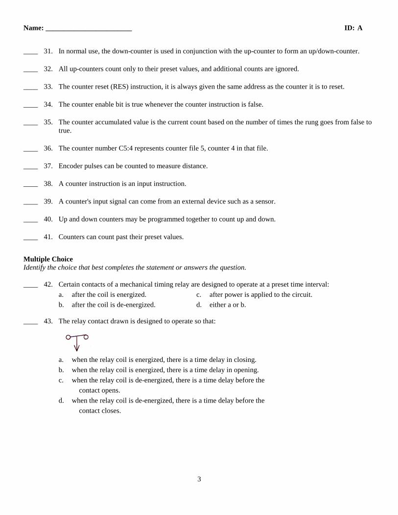
____ 43. The relay contact drawn is designed to operate so that:
a. when the relay coil is energized, there is a time delay in closing.
b. when the relay coil is energized, there is a time delay in opening.
c. when the relay coil is de-energized, there is a time delay before the
contact opens.
d. when the relay coil is de-energized, there is a time delay before the
contact closes.
Name: ________________________ ID: A
4
____ 44. In the hardwired circuit shown, the light will stay on:
a. as long as S1 is closed.
b. for 5 s after coil TD is energized.
c. for 5 s after coil TD is de-energized.
d. both a and c.
____ 45. Which one of the following timer parameters determines the time duration for the timing circuit?
a. Accumulated time. c. Timer address.
b. Preset time. d. Time base.
____ 46. Which one of the following timer parameters represents the value that increments as the timer is timing.?
a. Accumulated time. c. Timer address.
b. Preset time. d. Time base
____ 47. Which one of the following timer parameters determines the accuracy of the timer?
a. Accumulated time. c. Timer address.
b. Preset time. d. Time base.
____ 48. The timer file for SLC 500 controllers is:
a. T1 c. T3
b. T2 d. T4
____ 49. For the on-delay timer instruction shown the timer number is:
a. 0
b. 200
c. T4:3
d. 0.1
Name: ________________________ ID: A
5
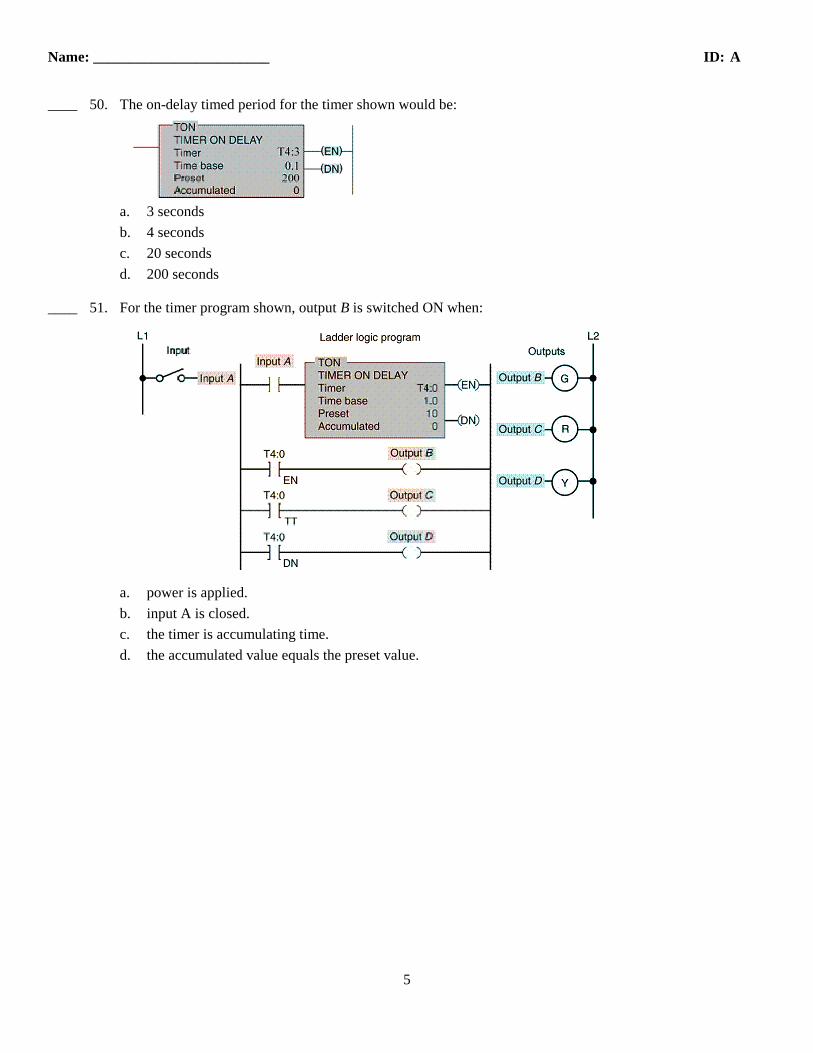
____ 50. The on-delay timed period for the timer shown would be:
a. 3 seconds
b. 4 seconds
c. 20 seconds
d. 200 seconds
____ 51. For the timer program shown, output B is switched ON when:
a. power is applied.
b. input A is closed.
c. the timer is accumulating time.
d. the accumulated value equals the preset value.
Name: ________________________ ID: A
6
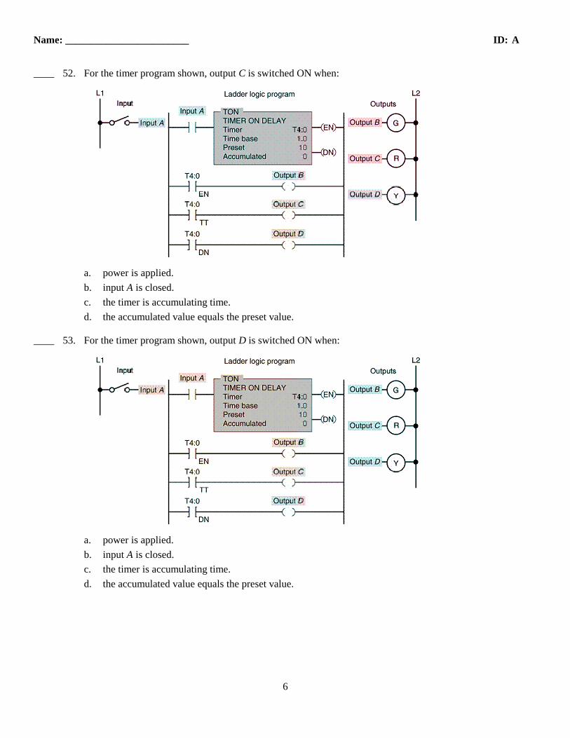
____ 52. For the timer program shown, output C is switched ON when:
a. power is applied.
b. input A is closed.
c. the timer is accumulating time.
d. the accumulated value equals the preset value.
____ 53. For the timer program shown, output D is switched ON when:
a. power is applied.
b. input A is closed.
c. the timer is accumulating time.
d. the accumulated value equals the preset value.
Name: ________________________ ID: A
7
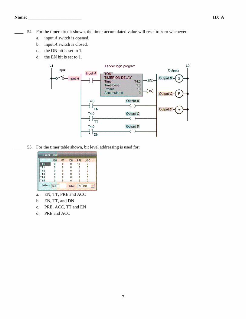
____ 54. For the timer circuit shown, the timer accumulated value will reset to zero whenever:
a. input A switch is opened.
b. input A switch is closed.
c. the DN bit is set to 1.
d. the EN bit is set to 1.
____ 55. For the timer table shown, bit level addressing is used for:
a. EN, TT, PRE and ACC
b. EN, TT, and DN
c. PRE, ACC, TT and EN
d. PRE and ACC
Name: ________________________ ID: A
8
____ 56. For the hardwired timer circuit shown, contact TD-1 is the ____ contact and TD-2 is the ____ contact.
a. ON, OFF
b. OFF, ON
c. instantaneous, timed
d. timed, instantaneous
____ 57. For the programmed timer circuit shown the ____ bit of the timer functions similar to an instantaneous
contact.
a. DN
b. EN
c. PB1
d. PB2
Name: ________________________ ID: A
9
____ 58. For the programmed timer circuit shown, the ____ bit of the timer functions similar to a
timed contact.
a. DN
b. EN
c. PB1
d. PB2
____ 59. The on-delay timer (TON) starts timing when the timer's:
a. ladder rung switches from false to true.
b. ladder rung switches from true to false.
c. accumulated value equals its preset value
d. accumulated is greater than its preset value
____ 60. The off-delay timer (TOF) starts timing when the timer's:
a. ladder rung switches from false to true.
b. ladder rung switches from true to false.
c. accumulated value equals its preset value
d. accumulated is greater than its preset value
Name: ________________________ ID: A
10
____ 61. For the programmed timer circuit shown, the pilot light should come on:
a. as soon as the switch is closed.
b. before the switch is closed.
c. for 15 seconds after the switch is opened.
d. both a and c.
____ 62. For the programmed timer circuit shown, when the switch is initially closed motor(s) _____ start(s)
immediately.
a. M1
b. M2
c. M3
d. all of these
Name: ________________________ ID: A
11
____ 63. For the programmed timer circuit shown, assume the switch is closed for 5 seconds and than
opened. After 12 seconds have elapsed motor(s) ____ will still be operating.
a. M1, M2, M3
b. M2, M3
c. M3
d. none of these
____ 64. The main difference between a TON and TOF timer is that the:
a. TON timer can maintain its accumulated time on loss of power
or logic continuity.
b. TOF timer can maintain its accumulated time on loss of power or logic
continuity.
c. TOF timer begins timing when logic continuity to the timing rung is lost.
d. TON timer begins timing when logic continuity to the timing rung is lost.
____ 65. The operation of a PLC retentive timer is similar to that of an:
a. electromagnetic pneumatic timer. c. off-delay timer.
b. electromechanical motor-driven timer. d. on-delay timer.
____ 66. The main difference between a PLC retentive and nonretentive timer is that the:
a. retentive timer can be programmed for much longer time delay periods.
b. nonretentive time can be programmed for much longer time delay periods.
c. retentive timer maintains the current time should power be removed from the device or
when the timer rung goes false.
d. nonretentive timer maintains the current time should power be removed from the device
or when the timer rung goes false.
Name: ________________________ ID: A
12
____ 67. Unlike the TON timer, the RTO timer requires a(n):
a. timer reset instruction. c. internal relay instruction.
b. input condition instruction. d. instantaneous contact instruction.
____ 68. When addressing an RES instruction, it must be addressed to:
a. a TOF instruction.
b. a TON instruction.
c. any address other than the of the RTO instruction.
d. the same address as that of the RTO instruction.
____ 69. The type of timer program shown is a:
a. retentive on-delay.
b. retentive off-delay.
c. nonretentive off-delay
d. nonretentive on-delay.
Name: ________________________ ID: A
13
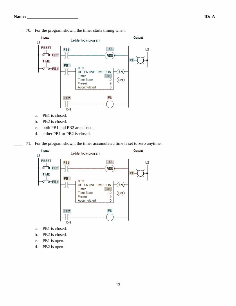
____ 70. For the program shown, the timer starts timing when:
a. PB1 is closed.
b. PB2 is closed.
c. both PB1 and PB2 are closed.
d. either PB1 or PB2 is closed.
____ 71. For the program shown, the timer accumulated time is set to zero anytime:
a. PB1 is closed.
b. PB2 is closed.
c. PB1 is open.
d. PB2 is open.
Name: ________________________ ID: A
14
____ 72. To reset a retentive timer, the:
a. AC time must be greater than the PR time.
b. PR time must be greater than the AC time.
c. AC time must equal the PR time.
d. none of these.
____ 73. The interconnecting of timers is commonly called:
a. grouping. c. sequencing.
b. programming. d. cascading.
____ 74. For the programmed timers shown, the output of timer T4:5 :
a. turns on after a 10-s time delay and remains on.
b. turns off after a 2-s time delay and remains off.
c. turns on after a 3-s time delay and remains on.
d. is pulsed on and off at 1-s intervals.
____ 75. Which instruction can best be used to turn an output coil on or off after the rung has been false for a desired
time?
a. RTO c. ONOF
b. TON d. TOF
____ 76. The amount of time for which a timer is programmed is called the:
a. Preset c. Set Point
b. Desired Time d. Lapsed Time
Name: ________________________ ID: A
15
____ 77. When the timing of a device is not reset on a loss of power, the timing is said to be:
a. continuous c. retentive
b. holding d. saved
____ 78. RES instructions are used with:
a. TOF timers c. RTO timers
b. TON timers d. all of these
____ 79. Programmed counters can:a. count up.b. count down.c. be combined to count up and down.d. all of these.
____ 80. The counter instruction is found on:a. all PLCs.b. small-size PLCs.c. medium-size PLCs.d. large-size PLCs.
____ 81. The PLC counter instruction is similar to the:a. internal relay instruction.b. transitional contact instruction.c. relay coil and contact instruction.d. timer instruction.
____ 82. The output of a PLC counter is energized when the:a. accumulated count equals the preset count.b. preset count is greater than the accumulated count.c. counter input rung is true.d. counter input rung is false.
____ 83. Which of the following is not usually associated with a PLC counter instruction?a. Addressb. Preset valuec. Time based. Accumulated value
____ 84. A PLC up-counter (CTU) counter counts:a. scan transitions.b. true-to-false transitions.c. false-to-true transitions.d. both b and c!
____ 85. When the up-counter reset is set to true, the following happens:a. the preset value is set to 0.b. the preset value increments.c. the accumulated value is set to 0.d. the accumulated value is set to maximum.
Name: ________________________ ID: A
16
____ 86. For the counter table shown, word level addressing is used for:
a. CU, CD, DN, OV, UN, and UAb. CU, CD, and DNc. OV and UNd. PRE and ACC
____ 87. In an up-counter, when the accumulated count exceeds the preset count without a reset, the accumulated count will:a. set itself to zero.b. start decrementing.c. continue incrementing.d. hold the accumulated value.
____ 88. When the accumulated count exceeds the preset count, the:a. accumulated value is set to zero.b. preset is set to zero.c. reset changes state.d. counter done bit is true.
____ 89. The counter RES instruction:a. is used to reset the counter.b. is given the same reference address as the counter instruction.c. decrements the count when actuated.d. both a and b.
____ 90. For the PLC counter to reset, the counter reset rung must:a. be true.b. be false.c. be either true or false, depending on the manufacturer.d. undergo a true-to-false transition.
____ 91. Normally counters are retentive. This means that if your accumulated count is up to 300 and power to your system is lost, when power is restored the accumulated count will be:a. 000b. 250c. 300d. 999
Name: ________________________ ID: A
17
____ 92. A one-shot, or transitional, contact:a. operates the same as an NO contact instruction.b. operates the same as an NC contact instruction.c. operates the same as a timed closed contact.d. closes for only one program scan when actuated.
____ 93. A PLC down-counter (CTD) counter counts:a. scan transitions.b. true-to-false transitions.c. false-to-true transitions.d. both b and c.
____ 94. The accumulated count of a CTD counter:a. increments with each true-to-false transition.b. decrements with each true-to-false transition.c. decrements with each false-to-true transition.d. increments with each false-to-true transition.
____ 95. The accumulated count of a CTU counter:a. increments with each true-to-false transition.b. decrements with each true-to-false transition.c. decrements with each false-to-true transition.d. increments with each false-to-true transition.
____ 96. A counter is to be programmed to keep track of the number of parts coming off a production line. If you wanted to subtract the number of rejected parts so your counter would count only the good parts, you would program:a. two up-counters.b. two down-counters.c. an up/down-counter.d. a counter with a transitional contact input.
Name: ________________________ ID: A
18
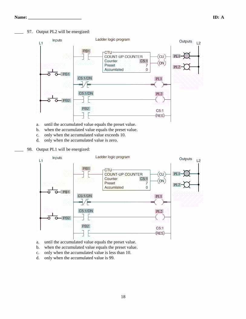
____ 97. Output PL2 will be energized:
a. until the accumulated value equals the preset value.b. when the accumulated value equals the preset value.c. only when the accumulated value exceeds 10.d. only when the accumulated value is zero.
____ 98. Output PL1 will be energized:
a. until the accumulated value equals the preset value.b. when the accumulated value equals the preset value.c. only when the accumulated value is less than 10.d. only when the accumulated value is 99.
Name: ________________________ ID: A
19
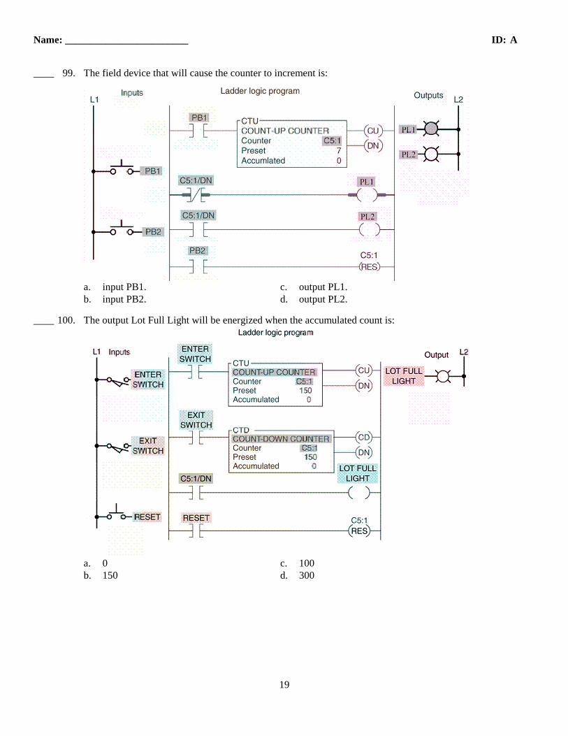
____ 99. The field device that will cause the counter to increment is:
a. input PB1. c. output PL1.b. input PB2. d. output PL2.
____ 100. The output Lot Full Light will be energized when the accumulated count is:
a. 0 c. 100b. 150 d. 300
Name: ________________________ ID: A
20
____ 101. Which instruction will cause the counter to decrement?
a. Enter switch input. c. Reset input.b. Exit switch input. d. Lot Full Light output.
____ 102. Which instruction, when true, will preset the counter to a count of zero?
a. Enter switch input. c. Reset input.b. Exit switch input. d. Lot Full Light output.
Name: ________________________ ID: A
21
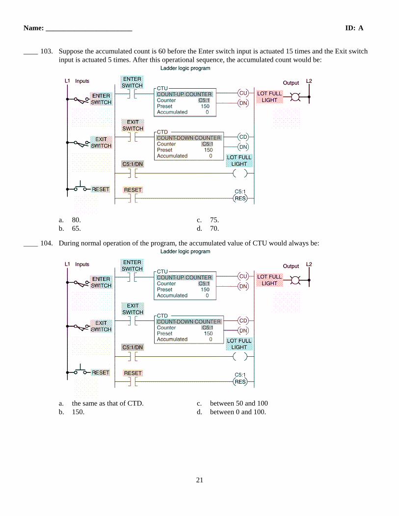
____ 103. Suppose the accumulated count is 60 before the Enter switch input is actuated 15 times and the Exit switch input is actuated 5 times. After this operational sequence, the accumulated count would be:
a. 80. c. 75.b. 65. d. 70.
____ 104. During normal operation of the program, the accumulated value of CTU would always be:
a. the same as that of CTD. c. between 50 and 100b. 150. d. between 0 and 100.
Name: ________________________ ID: A
22
____ 105. Assume the accumulated count is 100 and the following order of events then occurs: Exit switch input is actuated 20 times, Reset input is actuated 10 times, and Enter switch input is actuated 5 times. After this sequence, the accumulated count would be:
a. 100. c. 5.b. 115. d. 0.
____ 106. The counter file for SLC 500 controllers is:a. C2 c. C4b. C3 d. C5
____ 107. The figure shown illustrates the operation of a
____ 108. The counter program shown is designed to:
a. count up and count down.b. record the time of an event.c. count beyond the maximum count allowed per counter.d. count below the maximum count allowed per counter.
____ 109. Counter C5:1 starts counting:
a. when the accumulated value of C5:0 reaches 32,000.b. whenever input PB1 is actuated.c. whenever input PB2 is actuated.d. either b or c.
Name: ________________________ ID: A
24
____ 110. Output PL will be energized when:
a. the accumulated value of C5:0 reaches 32,000.b. counter C5:0 is reset.c. the accumulated value of C5:1 reaches 32,000.d. the accumulated value of C5:0 and C5:1 reaches 32,000.
____ 111. When output PL is energized, how many counts have occurred?
a. 4,000 c. 64,000b. 32,000 d. 99,999
Name: ________________________ ID: A
25
____ 112. If you wanted output PL to go on after a count of 40,000, you would change the preset count of C5:1 to:
a. 9,999. c. 8,000.b. 6,000. d. 12,000.
____ 113. When input PB2 is actuated:
a. output PL is switched off. c. counter C5:1 is reset.b. counter C5:0 is reset. d. all of these!
Name: ________________________ ID: A
26
____ 114. The 24-hour clock program shown uses:
a. 3 timers and 3 counters. c. 1 timer and 2 counters.b. 2 timers and 2 counters. d. 2 timers and 1 counter.
____ 115. For the 24-hour clock program, Counter C5:1 is preset for:
a. 12. c. 60.b. 24. d. 120.
Name: ________________________ ID: A
27
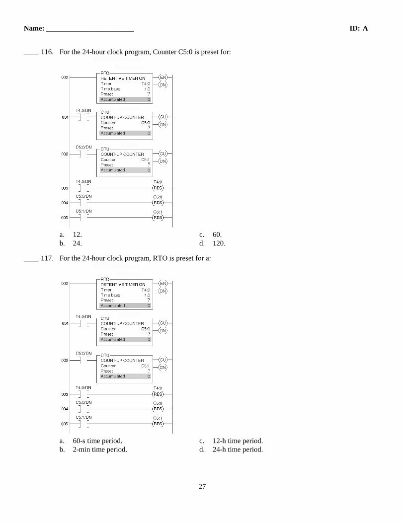
____ 116. For the 24-hour clock program, Counter C5:0 is preset for:
a. 12. c. 60.b. 24. d. 120.
____ 117. For the 24-hour clock program, RTO is preset for a:
a. 60-s time period. c. 12-h time period.b. 2-min time period. d. 24-h time period.
Name: ________________________ ID: A
28
____ 118. For the 24-hour clock program, a false-to-true transition of rung 002 increments the clock by:
a. 1 ms. c. 1 min.b. 1 s. d. 1 h.
____ 119. For the 24-hour clock program, Rung 003 undergoes a true-to-false transition once every:
a. 60 s. c. hour.b. 2 min. d. 24 h.
Name: ________________________ ID: A
29
____ 120. For the 24-hour clock program, assume the accumulated count of Counter C5:1 is 14 and that of C5:0 is 10. The correct time of day would be:
a. 2:10 p.m. c. 10:14 p.m.b. 10:14 a.m. d. 2:10 a.m.
ID: A
1
MECH 1500 Quiz 4 ReviewAnswer Section
TRUE/FALSE
1. ANS: T PTS: 1 2. ANS: T PTS: 1 3. ANS: T PTS: 1 4. ANS: T PTS: 1 5. ANS: F PTS: 1 6. ANS: T PTS: 1 7. ANS: T PTS: 1 8. ANS: F PTS: 1 9. ANS: T PTS: 1 10. ANS: T PTS: 1 11. ANS: T PTS: 1 12. ANS: F PTS: 1 13. ANS: F PTS: 1 14. ANS: T PTS: 1 15. ANS: F PTS: 1 16. ANS: T PTS: 1 17. ANS: F PTS: 1 18. ANS: T PTS: 1 19. ANS: T PTS: 1 20. ANS: F PTS: 1 21. ANS: T PTS: 1 22. ANS: T PTS: 1 23. ANS: T PTS: 1 24. ANS: T PTS: 1 25. ANS: F PTS: 1 26. ANS: F PTS: 1 27. ANS: F PTS: 1 28. ANS: F PTS: 1 29. ANS: T PTS: 1 30. ANS: T PTS: 1 31. ANS: T PTS: 1 32. ANS: F PTS: 1 33. ANS: T PTS: 1 34. ANS: F PTS: 1 35. ANS: T PTS: 1 36. ANS: T PTS: 1 37. ANS: T PTS: 1 38. ANS: F PTS: 1 39. ANS: T PTS: 1
ID: A
2
40. ANS: T PTS: 1 41. ANS: T PTS: 1
MULTIPLE CHOICE
42. ANS: D PTS: 1 43. ANS: D PTS: 1 44. ANS: B PTS: 1 45. ANS: B PTS: 1 46. ANS: A PTS: 1 47. ANS: D PTS: 1 48. ANS: D PTS: 1 49. ANS: C PTS: 1 50. ANS: C PTS: 1 51. ANS: B PTS: 1 52. ANS: C PTS: 1 53. ANS: D PTS: 1 54. ANS: A PTS: 1 55. ANS: B PTS: 1 56. ANS: C PTS: 1 57. ANS: B PTS: 1 58. ANS: A PTS: 1 59. ANS: A PTS: 1 60. ANS: B PTS: 1 61. ANS: D PTS: 1 62. ANS: D PTS: 1 63. ANS: C PTS: 1 64. ANS: C PTS: 1 65. ANS: B PTS: 1 66. ANS: C PTS: 1 67. ANS: A PTS: 1 68. ANS: D PTS: 1 69. ANS: D PTS: 1 70. ANS: A PTS: 1 71. ANS: B PTS: 1 72. ANS: D PTS: 1 73. ANS: D PTS: 1 74. ANS: D PTS: 1 75. ANS: D PTS: 1 76. ANS: A PTS: 1 77. ANS: C PTS: 1 78. ANS: C PTS: 1 79. ANS: D PTS: 1 80. ANS: B PTS: 1
ID: A
3
81. ANS: D PTS: 1 82. ANS: A PTS: 1 83. ANS: C PTS: 1 84. ANS: C PTS: 1 85. ANS: C PTS: 1 86. ANS: D PTS: 1 87. ANS: C PTS: 1 88. ANS: D PTS: 1 89. ANS: D PTS: 1 90. ANS: C PTS: 1 91. ANS: C PTS: 1 92. ANS: D PTS: 1 93. ANS: C PTS: 1 94. ANS: B PTS: 1 95. ANS: A PTS: 1 96. ANS: C PTS: 1 97. ANS: B PTS: 1 98. ANS: A PTS: 1 99. ANS: B PTS: 1 100. ANS: B PTS: 1 101. ANS: B PTS: 1 102. ANS: C PTS: 1 103. ANS: D PTS: 1 104. ANS: A PTS: 1 105. ANS: C PTS: 1 106. ANS: D PTS: 1 107. ANS: C PTS: 1 108. ANS: C PTS: 1 109. ANS: B PTS: 1 110. ANS: A PTS: 1 111. ANS: C PTS: 1 112. ANS: C PTS: 1 113. ANS: D PTS: 1 114. ANS: C PTS: 1 115. ANS: B PTS: 1 116. ANS: C PTS: 1 117. ANS: A PTS: 1 118. ANS: D PTS: 1 119. ANS: A PTS: 1 120. ANS: A PTS: 1