63
68-11732-122 EXB-IP & EXB-IP 8000 Ethernet Network Extender Module User Manual User Guide # S2-61089-122

68-11732-122
EXB-IP & EXB-IP 8000
Ethernet Network Extender Module User Manual
User Guide # S2-61089-122

CTI Products, Inc. EXB-IP User Guide
2 68-11732-122
Standard Limited Hardware Warranty LIMITED WARRANTY. Equipment manufactured by CTI Products, Inc. is warranted to be free from defects in material and workmanship for a period of ONE (1) YEAR from date of shipment to original purchaser. Under this warranty, our obligation is limited to repairing or replacing any equipment proved to be defective by our inspection within one year of sale to the original purchaser. This warranty shall not apply to equipment which has been repaired outside our plant in any way, so as to, in the judgment of CTI Products, Inc. affect its stability or reliability, nor which has been operated in a manner exceeding its specifications, nor which has been altered, defaced, or damaged by lightning. CUSTOMER REMEDIES. In the event of a defect, malfunction, or failure to conform to specifications established by the seller during the period shown, the customer shall call CTI Products, Inc. to obtain a Return Authorization Number and return the product or module, shipping and insurance prepaid. CTI Products, Inc., will then at its option, either repair or replace the product or module and return it, shipping prepaid, or refund the purchase price thereof. On-site labor at the purchaser's location is not included in this warranty. EQUIPMENT NOT MANUFACTURED BY CTI Products, Inc. Equipment not manufactured by CTI Products, Inc. is excluded from this warranty, but is subject to the warranty provided by its manufacturer, a copy of which will be supplied to you upon specific written request. NO OTHER WARRANTIES. The foregoing constitutes the sole and exclusive remedy of the buyer and exclusive liability of CTI Products, Inc., AND IS IN LIEU OF ANY AND ALL OTHER WARRANTIES EXPRESSED OR IMPLIED OR STATUTORY AS TO MERCHANTABILITY, FITNESS FOR PURPOSE SOLD, DESCRIPTION, QUALITY, PRODUCTIVENESS OR ANY OTHER MATTER. NO LIABILITY FOR CONSEQUENTIAL DAMAGES. WITHOUT LIMITING THE FOREGOING, IN NO EVENT SHALL CTI PRODUCTS, INC. OR ITS SUPPLIERS BE LIABLE FOR ANY DAMAGES WHATSOEVER (INCLUDING, WITHOUT LIMITATION, SPECIAL, INCIDENTAL OR CONSEQUENTIAL DAMAGES OR FOR LOSS OF BUSINESS PROFITS, BUSINESS INTERRUPTION, LOSS OF BUSINESS INFORMATION, OR OTHER PECUNIARY LOSS) ARISING OUT OF THE USE OF OR INABILITY TO USE CTI PRODUCTS, INC. EQUIPMENT BY PURCHASER OR OTHER THIRD PARTY, WHETHER UNDER THEORY OF CONTRACT, TORT (INCLUDING NEGLIGENCE), INDEMNITY, PRODUCT LIABILITY OR OTHERWISE, EVEN IF CTI PRODUCTS, INC. HAS BEEN ADVISED OF THE POSSIBILITY OF SUCH DAMAGES OR LOSSES. IN NO EVENT SHALL CTI PRODUCTS, INC.’S, LIABILITY EXCEED THE TOTAL AMOUNT PAID BY PURCHASER FOR THE EQUIPMENT GIVING RISE TO SUCH LIABILITY.
Location: CTI Products, Inc 1211 West Sharon Road Cincinnati, OH 45240 USA
Phone: +1.513.595.5900 Fax: +1.513.595.5983 Web: www.ctiproducts.com E-mail, Sales: [email protected] Technical Support: [email protected]
Information contained in this document is subject to change without notice and does not represent a commitment on the part of CTI Products, Inc. No part of this manual may be reproduced or transmitted in any form or by any means, electronic or mechanical, including photocopying and recording, for any purpose without the written permission of CTI Products, Inc. This manual describes products which include copyrighted CTI Products, Inc. computer programs in semiconductor memory. CTI Products, Inc. reserves all rights for these programs, including the exclusive right to copy or reproduce the copyrighted computer programs in any form. No copyrighted computer program contained in products described in this manual may be copied, reproduced, decompiled, disassembled, or reversed engineered in any manner without express written permission of CTI Products, Inc. The purchase of products from CTI Products, Inc. shall not be deemed to grant either directly or by implication, estoppel, or otherwise, any license under the copyrights, patents, or patent applications of CTI Products, Inc., except for the normal non-exclusive, royalty fee license to use that arises by operation of law in the sale of the product. Copyright (c) 2004-2012 CTI Products, Inc. All rights reserved EXB Module and WON are trademarks of CTI Products, Inc. ASTRO, MOTOROLA, and MOTOROLA SOLUTIONS and the Stylized M Logo are trademarks or registered trademarks of Motorola Trademark Holdings, LLC.
CTI Products, Inc. EXB-IP User Guide
3
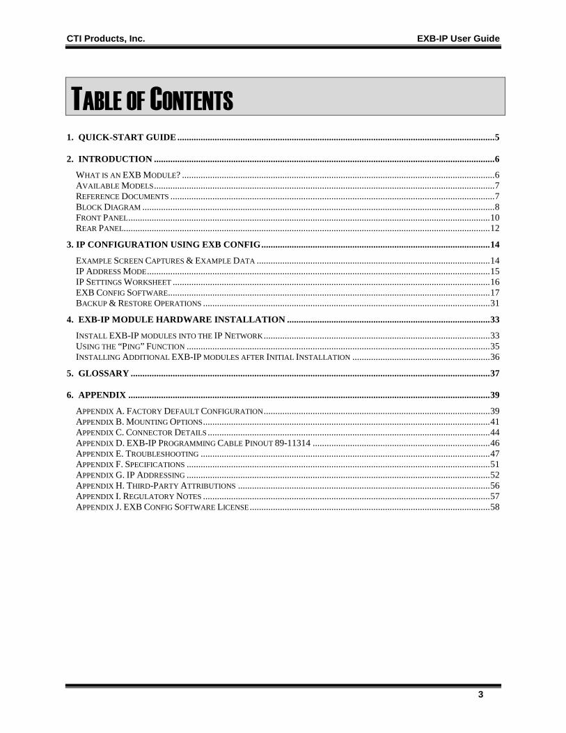
TABLE OF CONTENTS
1. QUICK-START GUIDE ........................................................................................................................................ 5
2. INTRODUCTION .................................................................................................................................................. 6 WHAT IS AN EXB MODULE? ...................................................................................................................................... 6 AVAILABLE MODELS .................................................................................................................................................. 7 REFERENCE DOCUMENTS ........................................................................................................................................... 7 BLOCK DIAGRAM ....................................................................................................................................................... 8 FRONT PANEL ........................................................................................................................................................... 10 REAR PANEL............................................................................................................................................................. 12
3. IP CONFIGURATION USING EXB CONFIG .................................................................................................. 14 EXAMPLE SCREEN CAPTURES & EXAMPLE DATA .................................................................................................... 14 IP ADDRESS MODE ................................................................................................................................................... 15 IP SETTINGS WORKSHEET ........................................................................................................................................ 16 EXB CONFIG SOFTWARE .......................................................................................................................................... 17 BACKUP & RESTORE OPERATIONS ........................................................................................................................... 31
4. EXB-IP MODULE HARDWARE INSTALLATION ....................................................................................... 33 INSTALL EXB-IP MODULES INTO THE IP NETWORK ................................................................................................. 33 USING THE “PING” FUNCTION .................................................................................................................................. 35 INSTALLING ADDITIONAL EXB-IP MODULES AFTER INITIAL INSTALLATION ........................................................... 36
5. GLOSSARY .......................................................................................................................................................... 37
6. APPENDIX ........................................................................................................................................................... 39 APPENDIX A. FACTORY DEFAULT CONFIGURATION ................................................................................................. 39 APPENDIX B. MOUNTING OPTIONS ........................................................................................................................... 41 APPENDIX C. CONNECTOR DETAILS ......................................................................................................................... 44 APPENDIX D. EXB-IP PROGRAMMING CABLE PINOUT 89-11314 ............................................................................ 46 APPENDIX E. TROUBLESHOOTING ............................................................................................................................ 47 APPENDIX F. SPECIFICATIONS .................................................................................................................................. 51 APPENDIX G. IP ADDRESSING .................................................................................................................................. 52 APPENDIX H. THIRD-PARTY ATTRIBUTIONS ............................................................................................................ 56 APPENDIX I. REGULATORY NOTES ........................................................................................................................... 57 APPENDIX J. EXB CONFIG SOFTWARE LICENSE ....................................................................................................... 58

CTI Products, Inc. EXB-IP User Guide
4
Revision History S2-61089-100 Initial Release S2-61089-105 Added definitions for flashing error codes S2-61089-120 Removed references to fiber transceivers and AUI Connector on rear panel
Added information on EXB-IP 8000 modules and configurable UDP Ports. Added information on EXB Config software
S2-61089-121 Changed default HTTP status page to Disabled.
Added pinout for EXB-IP programming cable and warning about using improper cable. Updated Setrtr information for custom configured units.
S2-61089-122 Added Information Assurance information.
Other minor updates
CTI Products, Inc. EXB-IP User Guide
5
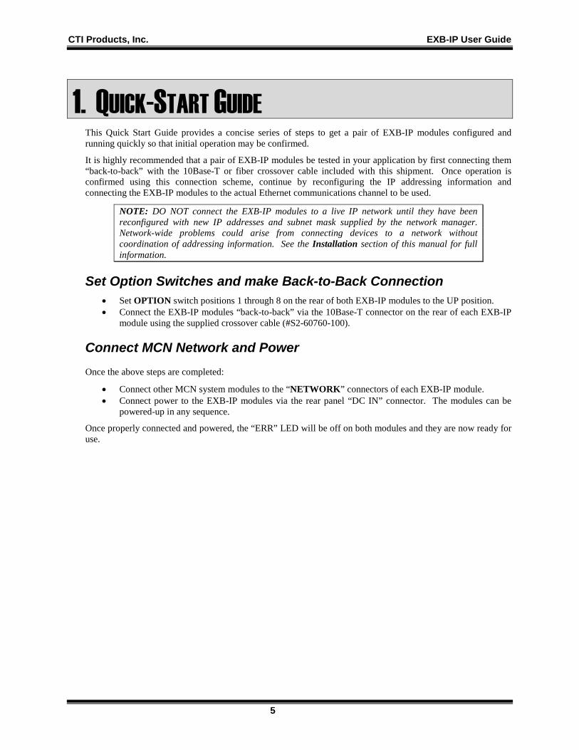
1. QUICK-START GUIDE This Quick Start Guide provides a concise series of steps to get a pair of EXB-IP modules configured and running quickly so that initial operation may be confirmed.
It is highly recommended that a pair of EXB-IP modules be tested in your application by first connecting them “back-to-back” with the 10Base-T or fiber crossover cable included with this shipment. Once operation is confirmed using this connection scheme, continue by reconfiguring the IP addressing information and connecting the EXB-IP modules to the actual Ethernet communications channel to be used.
NOTE: DO NOT connect the EXB-IP modules to a live IP network until they have been reconfigured with new IP addresses and subnet mask supplied by the network manager. Network-wide problems could arise from connecting devices to a network without coordination of addressing information. See the Installation section of this manual for full information.
Set Option Switches and make Back-to-Back Connection • Set OPTION switch positions 1 through 8 on the rear of both EXB-IP modules to the UP position. • Connect the EXB-IP modules “back-to-back” via the 10Base-T connector on the rear of each EXB-IP
module using the supplied crossover cable (#S2-60760-100).
Connect MCN Network and Power Once the above steps are completed:
• Connect other MCN system modules to the “NETWORK” connectors of each EXB-IP module. • Connect power to the EXB-IP modules via the rear panel “DC IN” connector. The modules can be
powered-up in any sequence.
Once properly connected and powered, the “ERR” LED will be off on both modules and they are now ready for use.

CTI Products, Inc. EXB-IP User Guide
Introduction 6
2. INTRODUCTION WHAT IS AN EXB MODULE?
The EXB System Extender Modules are members of the Monitoring and Control Network (MCN™) family of control products. They are used to connect multiple MCN networks together or to extend the length of an MCN network beyond 4000 feet. Therefore, multiple remote comparators can be controlled from a central site.
The EXB System Extender Modules allow simultaneous monitoring and control of Master and Slave comparators in wide-area voting systems. Multiple EXB modules can connect multiple MCN networks in real time, spanning distances from a mile to worldwide. Data transfer between distant networks is "live", delayed only by the transit time through the EXB modules and the data rate across the link.
The EXB-IP System Extender Module uses any 10Base-T copper-based Ethernet channel. (Other EXB models are available that utilize other long-distance media, such as analog or digital phone lines and microwave channels.)
The EXB-IP module utilizes the IP protocol over an Ethernet media and both can coexist on a wide-area IP network with other IP devices such as workstations, servers, and IP routers. Additionally, they can exist on dedicated Ethernet IP networks, where the only devices on the network are EXB-IP modules and (optionally) physical layer hubs.
Basic Application Figure 1 shows a comparator system that is located in a different building than the console equipment. Standard MCN CIB modules connect to the comparators and IIB modules connect to the console. The length of the MCN network is normally limited to 4000 feet. As shown in this diagram, a pair of EXB System Extender Modules can greatly extend the MCN network using Ethernet channels.
CA-80672-100
COMPARATORS
CIB
CIB
IIB
IIB
CONSOLEELECTRONICS
1
T
P/S
T
CONSOLE
P/S
EXB
T T
BUILDING 1 BUILDING 2
EXB
2
ETHERNETCHANNEL
Figure 1 Extending Comparator Status & Control Signals to a Console with EXB Modules
For monitoring, the CIB Comparator Interface Modules in Building 2 accept the logic level comparator status indications (Vote, Receive, Disable, and Fail) and send status messages over the MCN network. The EXB System Extender Module at Building 2 passes the status messages over the Ethernet channel to the EXB System Extender Module at Building 1. The EXB module at Building 1 passes the status information to the IIB modules over the local MCN Network. The IIB modules then convert the status messages to logic outputs for use by the console.
For controlling, the Force-Vote and Disable control functions from the console in Building 1 are passed through the IIB modules, through the pair of EXB modules, and to the CIB modules in Building 2. The CIB modules convert the control messages to logic levels to control the comparator.
CTI Products, Inc. EXB-IP User Guide
Introduction 7
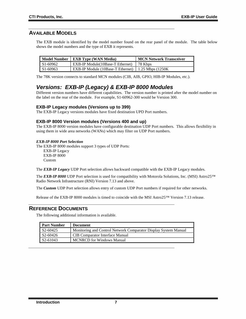
AVAILABLE MODELS The EXB module is identified by the model number found on the rear panel of the module. The table below shows the model numbers and the type of EXB it represents.
Model Number EXB Type (WAN Media) MCN Network Transceiver S1-60962 EXB-IP Module(10Base-T Ethernet) 78 Kbps S1-60963 EXB-IP Module (10Base-T Ethernet) 1.25 Mbps (1250K
The 78K version connects to standard MCN modules (CIB, AIB, GPIO, HIB-IP Modules, etc.).
Versions: EXB-IP (Legacy) & EXB-IP 8000 Modules Different version numbers have different capabilities. The version number is printed after the model number on the label on the rear of the module. For example, S1-60962-300 would be Version 300.
EXB-IP Legacy modules (Versions up to 399) The EXB-IP Legacy versions modules have fixed destination UPD Port numbers.
EXB-IP 8000 Version modules (Versions 400 and up) The EXB-IP 8000 version modules have configurable destination UDP Port numbers. This allows flexibility in using them in wide area networks (WANs) which may filter on UDP Port numbers. EXB-IP 8000 Port Selection The EXB-IP 8000 modules support 3 types of UDP Ports: EXB-IP Legacy EXB-IP 8000 Custom The EXB-IP Legacy UDP Port selection allows backward compatible with the EXB-IP Legacy modules.
The EXB-IP 8000 UDP Port selection is used for compatibility with Motorola Solutions, Inc. (MSI) Astro25™ Radio Network Infrastructure (RNI) Version 7.13 and above.
The Custom UDP Port selection allows entry of custom UDP Port numbers if required for other networks. Release of the EXB-IP 8000 modules is timed to coincide with the MSI Astro25™ Version 7.13 release.
REFERENCE DOCUMENTS The following additional information is available.
Part Number Document S2-60425 Monitoring and Control Network Comparator Display System Manual S2-60426 CIB Comparator Interface Manual S2-61043 MCNRCD for Windows Manual

CTI Products, Inc. EXB-IP User Guide
Introduction 8
BLOCK DIAGRAM As shown in Figure 2, there are three sources of message packets within the EXB module. The first source is the MCN NETWORK connector on the front of the module. The second is the 10BaseT Ethernet media connector on the rear of the module. The third source is the Control Neuron Processor. Message packets originating from any of these sources are sent to the other two.
MCN NETWORK
Side A
MCN ROUTER
MCN TRANSCEIVER
78K or 1250
“DC IN” Connector
“NETWORK” Connector
“10BaseT” Connector
Side B
RS-232 Serial Port
(Configuration)
POWER SUPPLY
CPU To
Ethernet Channel
ASYNC Port
Figure 2 EXB Network Extender Module Block Diagram
• The “NETWORK” connector attaches to the local MCN network using a compatible transceiver internal to the EXB module and is associated with Side B of the internal router.
• One of the Ethernet connectors attaches to the Ethernet channel, providing communication to additional EXB modules at remote sites. These ports are associated with Side A of the internal router.
• The CPU controls the overall operation of the module.
MCN Router Function The internal MCN router in each EXB module may be configured as a repeater, or custom-configured router. The easiest configuration is as a repeater, where all messages which enter the EXB module on the MCN Network or the Ethernet (Or fiber) port are passed to the other port. EXB modules normally ship with the router set up as a repeater unless the system is a Custom Configured system with a Custom Configuration documentation package (KA-8xxxx-xxx)
If the module is part of a Custom Configured system, there will be a special configuration for each EXB in the system. Typically this is used when there are multiple 78K networks feeding into a 1250 network. The internal routers will be configured to pass the MCN status traffic "upstream" to the PCs on the 1250 network, but not back to the other 78K networks.
Central Processor (CPU) The CPU controls the overall module. Ethernet channel parameters can be configured and displayed via the serial port using the EXB Config program.
Ethernet Connector The 10BaseT connector implements IEEE standard Ethernet at 10 Mbps.

CTI Products, Inc. EXB-IP User Guide
Introduction 9
The EXB-IP Network Extender Module utilizes IP (Internet Protocol) to implement the link to other EXB-IP modules. Both Unicast/Replicated and Multicast addressing is supported using UDP transport. “APPENDIX F. IP ADDRESSES” provides more detail about IP addressing. The IP “port numbers” used by these EXB-IP modules are 1100 (destination) and 1283 (source).
UDP Ports UDP (and TCP) Port numbers are used in networking to provide multiple connections to and from an IP device (ex: a web browser or email in a PC). IP Routers and firewalls are often configured to filter traffic based upon their destination (and sometimes source) port numbers.
The original EXB-IP modules had fixed source & destination UDP Ports. To allow for more flexibility, the EXB-IP 8000 modules allow user-selectable destination UDP Ports.
The EXB-IP modules use UDP Ports in their communications as shown below:
Source UDP Port
Destination UDP Port
Device
(Fixed)
Legacy (1100)
EXB-IP 8000 Port
User Configurable
EXB-IP Legacy Module
1283 Fixed No No
EXB-IP 8000 Module
1283 Selectable Selectable Yes 1 – 65534
The EXB-IP 8000 Port is a dedicated UDP Port used in Motorola Solutions Inc. (MSI) Astro25™ networks (version 7.13 and up). The MSI RNI (Radio Network Infrastructure) can be configured to pass EXB-IP 8000 module traffic between sites.
EXB-IP 8000 modules may be used in systems with EXB-IP Legacy modules. Since the legacy modules use fixed ports, the EXB-IP 8000 modules must be configured for the Legacy UDP Ports to communicate with the legacy modules.
The UDP Port is a global setting in the EXB Config software. Therefore, all EXB modules will use the same destination UDP Port number. If there are any Legacy EXB-IP modules in the system, all modules will use the Legacy Port.
CTI Products, Inc. EXB-IP User Guide
Introduction 10
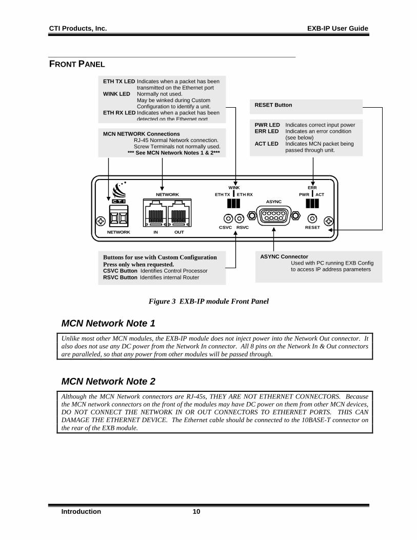
FRONT PANEL
1 2 3 4
5
9876
PWRWINK
NETWORK
OUT
ASYNC
NETWORK IN
ERR
CSVC RSVC RESET
ETH TX ETH RX ACT
Figure 3 EXB-IP module Front Panel
MCN Network Note 1 Unlike most other MCN modules, the EXB-IP module does not inject power into the Network Out connector. It also does not use any DC power from the Network In connector. All 8 pins on the Network In & Out connectors are paralleled, so that any power from other modules will be passed through.
MCN Network Note 2 Although the MCN Network connectors are RJ-45s, THEY ARE NOT ETHERNET CONNECTORS. Because the MCN network connectors on the front of the modules may have DC power on them from other MCN devices, DO NOT CONNECT THE NETWORK IN OR OUT CONNECTORS TO ETHERNET PORTS. THIS CAN DAMAGE THE ETHERNET DEVICE. The Ethernet cable should be connected to the 10BASE-T connector on the rear of the EXB module.
ETH TX LED Indicates when a packet has been transmitted on the Ethernet port
WINK LED Normally not used. May be winked during Custom Configuration to identify a unit.
ETH RX LED Indicates when a packet has been detected on the Ethernet port
MCN NETWORK Connections RJ-45 Normal Network connection.
Screw Terminals not normally used. *** See MCN Network Notes 1 & 2***
ASYNC Connector Used with PC running EXB Config to access IP address parameters
RESET Button
Buttons for use with Custom Configuration Press only when requested. CSVC Button Identifies Control Processor RSVC Button Identifies internal Router
PWR LED Indicates correct input power ERR LED Indicates an error condition
(see below) ACT LED Indicates MCN packet being
passed through unit.
CTI Products, Inc. EXB-IP User Guide
Introduction 11
Front Panel Indicators – Additional Information ETH RX LED (Yellow) – Indicates when a packet has been detected on the Ethernet port. NOTE: Flashing of this LED does NOT necessarily mean that a packet addressed to this EXB module has been received, just that a packet has been detected on the Ethernet network.
ERR LED (Red) – Indicates a possible error condition. • Always On: A diagnostic error has been detected. Press the “RESET” button. If the “ERR” LED now
stays off, the EEPROM contained invalid data and has been reinitialized. Any non-volatile information must be re-entered by using the EXB Config program. If the LED stays on solid, a hardware problem is indicated. Contact technical support for assistance.
• Slow Flash: (once per second) Router configuration information is insufficient. Using setrtr2.exe, re-program the internal router nodes.
• Quick Flash: (twice per second) IP address configuration is insufficient. Using EXB Config, configure the IP addressing parameters.

CTI Products, Inc. EXB-IP User Guide
Introduction 12
REAR PANEL
DC IN
OPTION
10BASE-T
1 2 3 4 5 6 7 8ON
Figure 4 EXB-IP module Rear Panel
10Base-T Warning Do not connect the 10Base-T connector to an MCN Network connector. Damage could result.
Option Switch Settings
1 2 3 4 5 6 7 8 ON 1. Must be Up 2. HTTP Page Default Down Up = Enabled Down = Disabled 3. Not Used Default Up 4. Not Used Default Up 5. Not Used Default Up 6. Not Used Default Up 7. 8.
Ethernet Mode Switch: 7 8 10Base-T UP UP Ethernet Connector
DC IN Input Power This powers only this unit. Power is not passed to the Network Out connector.
OPTION Switches Selects the active Ethernet
connector. See table below.
Ethernet Connector *** See 10Base-T Warning ***
CTI Products, Inc. EXB-IP User Guide
Introduction 13
HTTP Page Security Note The EXB-IP and EXB-IP 8000 units have an HTTP page that shows the status of the unit, including the IP parameters programmed into it and its On-Line / Off-Line status. This is useful for system troubleshooting. This feature is turned off at the factory by default. If your network security policies mandate against this type of data being accessible through HTTP pages, verify that the HTTP page by setting Switch 2 Down and resetting the unit. For further security, restrict physical access to the unit and the networks to which it connects. If your network security policies allow you to use HTTP pages and you desire to have the HTTP page turned on for troubleshooting, set Switch 2 Up and reset the unit. Note: Some networks (including Motorola Solutions, Inc. Radio Network Infrastructure - RNI) have routers and or firewalls that restrict HTTP traffic between certain network segments. If you have such a system, you may not be able to open the HTTP page from a different IP subnet, even if you have the HTTP page enabled on the EXB-IP unit.
CTI Products, Inc. EXB-IP User Guide
IP Configuration – EXB Config 14
3. IP CONFIGURATION USING EXB CONFIG This section describes the steps necessary to configure the IP address parameters of EXB-IP modules for an IP network that is shared with other IP devices (such as workstations, servers, etc.).
NOTE: DO NOT connect the EXB-IP module to a live IP network until it has been reconfigured with new IP addresses and subnet mask supplied by the network manager. Network-wide problems could arise from connecting devices to a network without coordination of addressing information. For usage with dedicated fiber segments, see the note below.
Units are shipped factory-programmed so that they can be tested in a back-to-back mode with a crossover Ethernet cable. The initial tests in this mode do not require field programming. However, the modules must be programmed before installing in a real network.
EXAMPLE SCREEN CAPTURES & EXAMPLE DATA Example screen captures of the EXB Config program are shown in the manual to give the reader an example of what to expect during setup, configuration, and operation of the software. Newer versions of the software may include updated windows with slightly different wording or additional fields.
Data shown in example screen captures is presented only for example purposes only. It does not reflect any particular user's system.
Various sections of the manual focus on particular topics. Example screen captures within a section are presented as examples of the topics covered in that section. Example data show in the screen captures in one section may not apply to screen captures shown or system configuration described in different sections.
IP Addresses, Subnet Masks, Gateway IP Addresses, and UDP port numbers are taken from test systems in a lab and are used as examples only. They will not reflect your system settings. They should not be taken as recommendations.
Since the test system used in preparing this manual did not include the various IP routers used in an ASTRO® 25 7.x system, the example settings do not coincide with the requirements and recommendations of Motorola's IP Plan. Each system is different; refer to the documentation for your system for the proper IP addresses and UDP port numbers.
CTI Products, Inc. EXB-IP User Guide
IP Configuration – EXB Config 15
IP ADDRESS MODE EXB-IP modules can communicate with other EXB-IP modules using either “Unicast/Replicated” or “Multicast” mode.
Unicast/Replicated Unicast/Replicated addressing mode allows point-to-point or point-to-multipoint connections in any IP network. It is used in the following configurations:
• Point-to-Point connection should be used if only two modules will be communicating.
• Point-to-Multipoint connection can be used when Multicast is not supported on the IP network (non-preferred)
In multipoint applications, Unicast/Replicated address mode uses more Ethernet channel bandwidth than Multicast mode. For each MCN data packet received, an EXB-IP module in Unicast/Replicated mode will send out an Ethernet packet to each remote EXB-IP module. For example, in a system with 5 EXB-IP modules, each module would generate 4 Ethernet packets for each MCN packet received. (A good portion of this extra traffic can be eliminated in systems that have multiple comparator sites feeding only 1 PC site. In this application, each of the comparator site EXB-IP modules can be programmed to send data to only the Central Site EXB.)
Multicast Multicast addressing mode allows efficient point-to-multipoint communications in a network. A single MCN message packet entering any one of the EXB-IP modules results in a single multicast IP packet being sent out the Ethernet port of that module to be received by all other EXB-IP module members configured to the same Multicast IP address. Because only one IP packet is generated for every MCN message packet, multicast addressing mode uses far less network bandwidth than Unicast/Replicated.
Before choosing multicast addressing mode, it is important to determine the following capabilities of the IP network to which the EXB-IP modules will be connected:
• IP routers must be capable of handling IP multicast traffic. • IP routers must have IP multicast enabled • IP routers must forward the appropriate multicast traffic destined to the destination UDP Port number
in use by the EXB-IP modules in the channel. • If the routers filter multicast traffic based on source UDP Ports, they must forward packets from a
source UDP Port of 1283.
CTI Products, Inc. EXB-IP User Guide
IP Configuration – EXB Config 16
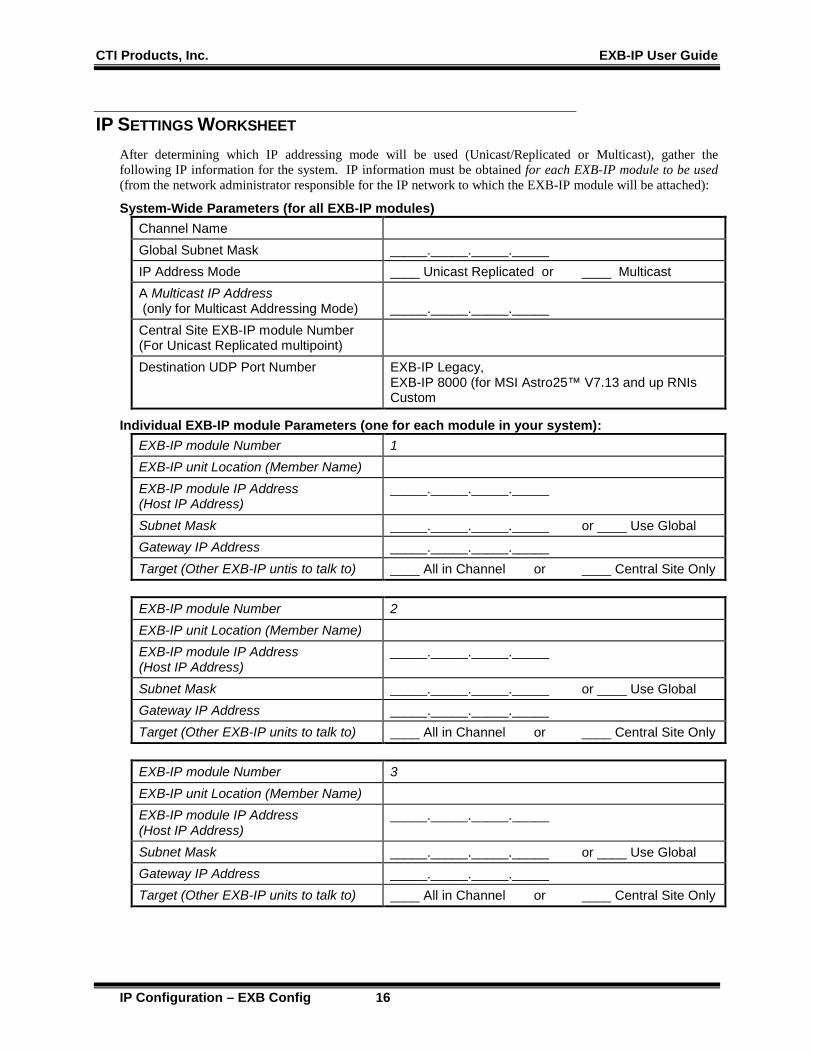
IP SETTINGS WORKSHEET After determining which IP addressing mode will be used (Unicast/Replicated or Multicast), gather the following IP information for the system. IP information must be obtained for each EXB-IP module to be used (from the network administrator responsible for the IP network to which the EXB-IP module will be attached):
System-Wide Parameters (for all EXB-IP modules) Channel Name Global Subnet Mask _____._____._____._____ IP Address Mode ____ Unicast Replicated or ____ Multicast A Multicast IP Address (only for Multicast Addressing Mode)
_____._____._____._____
Central Site EXB-IP module Number (For Unicast Replicated multipoint)
Destination UDP Port Number EXB-IP Legacy, EXB-IP 8000 (for MSI Astro25™ V7.13 and up RNIs Custom
Individual EXB-IP module Parameters (one for each module in your system): EXB-IP module Number 1 EXB-IP unit Location (Member Name) EXB-IP module IP Address (Host IP Address)
_____._____._____._____
Subnet Mask _____._____._____._____ or ____ Use Global Gateway IP Address _____._____._____._____ Target (Other EXB-IP untis to talk to) ____ All in Channel or ____ Central Site Only
EXB-IP module Number 2 EXB-IP unit Location (Member Name) EXB-IP module IP Address (Host IP Address)
_____._____._____._____
Subnet Mask _____._____._____._____ or ____ Use Global Gateway IP Address _____._____._____._____ Target (Other EXB-IP units to talk to) ____ All in Channel or ____ Central Site Only
EXB-IP module Number 3 EXB-IP unit Location (Member Name) EXB-IP module IP Address (Host IP Address)
_____._____._____._____
Subnet Mask _____._____._____._____ or ____ Use Global Gateway IP Address _____._____._____._____ Target (Other EXB-IP units to talk to) ____ All in Channel or ____ Central Site Only

CTI Products, Inc. EXB-IP User Guide
IP Configuration – EXB Config 17
EXB CONFIG SOFTWARE The purpose of the EXB Config software is to configure the IP parameters for EXB-IP modules. It is normally installed on a Service Laptop, although it can be installed on a PC running one of the MCN software packages (MCNRCD, MCN Server, MCN Advanced Server, or MCN Server 8000).
The EXB Config software provides the following functions:
• Entry of IP Parameters for the EXB-IP modules in a channel
• Uploading the configuration to the EXB-IP modules.
• Verifying the parameters loaded into the EXB-IP modules
• Saving and Printing module IP configuration to a file for archiving purposes
In order to configure an EXB-IP module, an RS-232 connection is required from the user's PC to the EXB-IP module being configured.
Minimum PC Requirements Minimum PC requirements to install and operate the EXB Config Software are:
• IBM Compatible PC
• RS-232 port
• 512 MB RAM
• 100 MB free disk space for program and support files
• SVGA adapter and monitor
• Mouse and Keyboard
• Windows XP SP3 or higher
Step 1. Install EXB Config It is recommended that the EXB Config software be installed on a PC with all the appropriate Information Assurance precautions taken as per the network security polices in place for the system. It is recommended that Anti-Virus software be installed and the appropriate Windows Hardening Kit be installed on the PC.
You must have Administrator rights to install the software.
The EXB Config software will be used to configure IP address parameters of EXB-IP modules, and is included on the CDROM shipped with the modules. Use the following steps to install EXB Config on your PC:
a. Insert the EXB Config CDROM in your CDROM drive. b. Click the Windows Start button, choose “Run...”, click Browse… , select the “Setup.exe”
application on the CDROM, and click Open . c. Follow the instructions displayed by the “Setup” application.
CTI Products, Inc. EXB-IP User Guide
IP Configuration – EXB Config 18
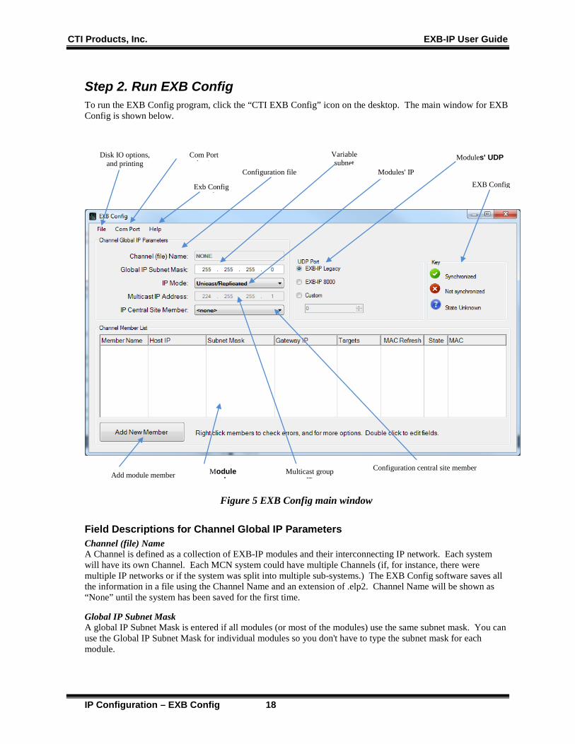
Step 2. Run EXB Config To run the EXB Config program, click the “CTI EXB Config” icon on the desktop. The main window for EXB Config is shown below.
Figure 5 EXB Config main window
Field Descriptions for Channel Global IP Parameters Channel (file) Name A Channel is defined as a collection of EXB-IP modules and their interconnecting IP network. Each system will have its own Channel. Each MCN system could have multiple Channels (if, for instance, there were multiple IP networks or if the system was split into multiple sub-systems.) The EXB Config software saves all the information in a file using the Channel Name and an extension of .elp2. Channel Name will be shown as “None” until the system has been saved for the first time.
Global IP Subnet Mask A global IP Subnet Mask is entered if all modules (or most of the modules) use the same subnet mask. You can use the Global IP Subnet Mask for individual modules so you don't have to type the subnet mask for each module.
Add module member
Modules' UDP
Configuration file
Module b
Variable subnet
Modules' IP EXB Config
Multicast group IP
Configuration central site member
Com Port l i
Exb Config H l
Disk IO options, and printing
CTI Products, Inc. EXB-IP User Guide
IP Configuration – EXB Config 19
IP Address Mode Unicast/Replicated or Multicast. (See Selecting the Addressing Mode above.) Note that Multicast mode for EXB-IP modules is not supported on Astro25™ RNIs.
Multicast IP Address The IP address used in Multicast systems. The first number must be between 224 & 239. This parameter is invalid if the configuration’s “IP Mode” is not set to “Multicast”.
IP Central Site Member If you have a system in which a number of remote EXB-IP modules at comparator sites talk to one central EXB-IP module at the PC site, select the name of the EXB-IP module at the PC site.
UDP Port Select a standard port type for either EXB-IP Legacy modules or EXB-IP 8000 modules. Alternatively, select a custom port number.
Field Descriptions for Channel Member List Member Name Alias name for each EXB-IP module, typically a site name or location.
Host IP This is the IPv4 address for each EXB-IP module member.
Subnet Mask This is the individual Subnet Mask for each EXB-IP module. If all the IP Subnet Masks are the same, you can enter it once in the Global IP Subnet Mask and select "Global" in this field.
Gateway IP When an EXB-IP module must communicate with a module on a different IP subnet, it must talk through a Gateway. Enter the IP address for this Gateway. It must be on the same IP subnet as the EXB-IP module Host IP Address. For example: Global IP Subnet Mask: 255.255.0.0 EXB-IP module #1 Host IP: 192.180.0.5 Gateway IP: 192.180.0.1 EXB-IP module #2 Host IP: 192.200.0.7 Gateway IP: 192.200.0.1 Since the Host IP Addresses for the two EXB-IP modules are different in the first two octets (192.180 versus 192.200), they are on different subnets.
Targets This indicates which other EXB-IP modules that this module will send messages to. There are two choices:
• All in Channel, member will communicate with all other members, or • Central Site only, member will communicate only with Central Site
Central Site Mode If the system being constructed does not require message packets to flow between devices at different remote sites, but only between a remote site and a single central site, use Central Site mode. This reduces IP network bandwidth required. To use Central Site mode: • Set IP Central Site Member Name to the name of the EXB-IP module with its NETWORK port
connected to the MCN network at the Host Computer site. • For all remote EXB-IP modules that need to exchange message packets with only the Central Site
EXB-IP, set its Targets selection to Central Site.
CTI Products, Inc. EXB-IP User Guide
IP Configuration – EXB Config 20
All In Channel If message packets must flow between remote sites and the Central site and also from one remote site to another remote site, use All In Channel mode.
MAC Refresh This tells the EXB-IP module to send periodic refresh messages for Ethernet switches and routers that need them to refresh their ARP cache tables.
State This indicates whether the IP data in the EXB-IP module matches (Synchronized, green check mark) or does not match (Not synchronized, red X) the data on the screen. If an EXB-IP module is not connected, then a Question Mark will be displayed (State Unknown).
CTI Products, Inc. EXB-IP User Guide
IP Configuration – EXB Config 21
Step 3. Editing IP Address Parameters The IP information that was gathered from the IP Network Administrator, as described at the beginning of Section 2 of this manual, must be entered into the EXB Config program as follows:
a. Specify the Channel Global IP Parameters: • If you wish to change the “Channel Name”, choose File – New Channel, enter an appropriate
name, then click OK. • Click on the “Global IP Subnet Mask” textbox, then enter the Subnet Mask assigned the EXB-
IP modules by the IP Network Administrator. • If different subnet masks are specified for different groups of EXB-IP modules, enter the
subnet mask that is common to most of the EXB-IP modules in the group. • If a different subnet mask is assigned to every EXB-IP module, leave this field with its default
value. • After reviewing the information concerning IP Addressing Modes in Appendix F, choose either
“Unicast/Replicated” or “Multicast” from the “IP Address Mode” drop-down list. • If “Multicast” was selected above, click on the “Multicast IP Address” box and enter the
Multicast IP Address that the IP Network Administrator has assigned to this group of EXB-IP modules.
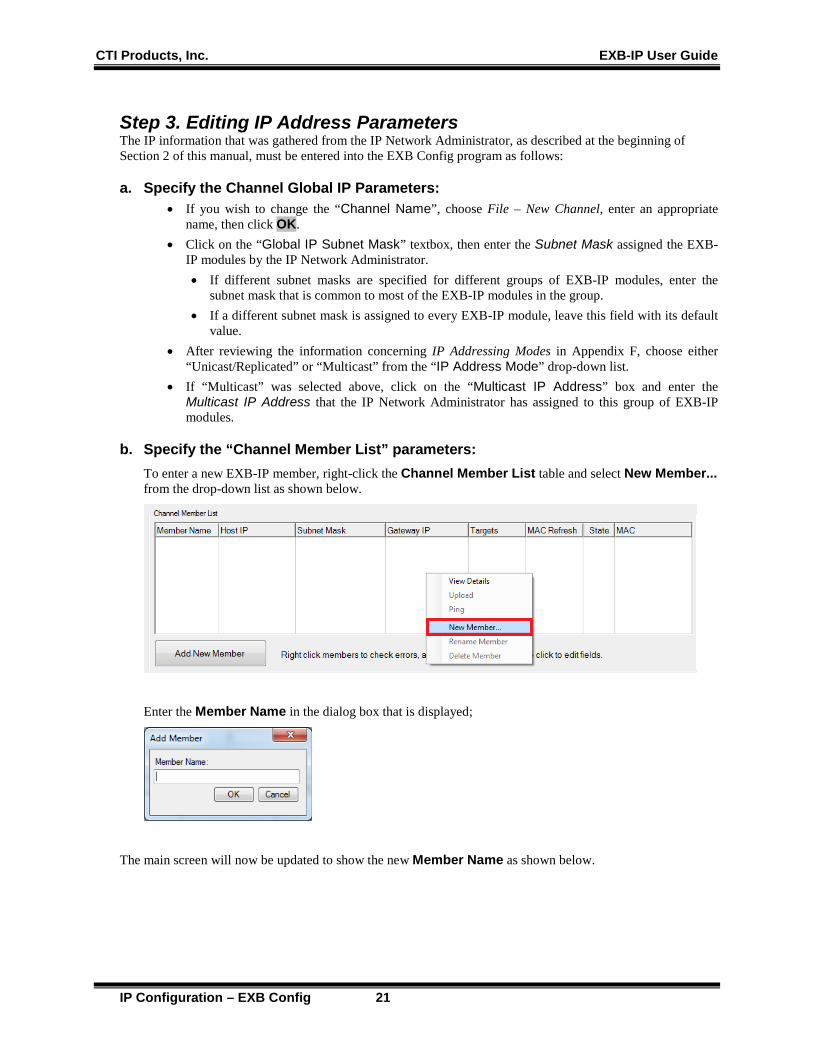
b. Specify the “Channel Member List” parameters: To enter a new EXB-IP member, right-click the Channel Member List table and select New Member... from the drop-down list as shown below.
Enter the Member Name in the dialog box that is displayed;
The main screen will now be updated to show the new Member Name as shown below.
CTI Products, Inc. EXB-IP User Guide
IP Configuration – EXB Config 22
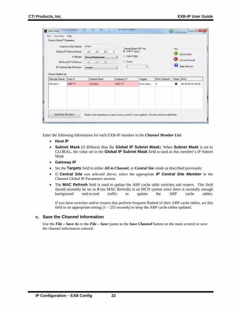
Enter the following information for each EXB-IP member in the Channel Member List: • Host IP • Subnet Mask (if different than the Global IP Subnet Mask). When Subnet Mask is set to
GLOBAL, the value set in the Global IP Subnet Mask field is used as this member’s IP Subnet Mask
• Gateway IP • Set the Targets field to either All in Channel, or Central Site mode as described previously • If Central Site was selected above, select the appropriate IP Central Site Member in the
Channel Global IP Parameters section. • The MAC Refresh field is used to update the ARP cache table switches and routers. This field
should normally be set to 0 (no MAC Refresh) in an MCN system since there is normally enough background end-to-end traffic to update the ARP cache tables. If you have switches and/or routers that perform frequent flushed of their ARP cache tables, set this field to an appropriate setting (1 – 255 seconds) to keep the ARP cache tables updated.
c. Save the Channel Information Use the File – Save As or the File – Save (same as the Save Channel button on the main screen) to save the channel information entered.

CTI Products, Inc. EXB-IP User Guide
IP Configuration – EXB Config 23
Configuration Errors The fields highlighted in red indicate configuration errors. To check the configuration errors, right-click any member row with red highlighted fields. A pop-up will appear. Select "What are my errors?"
A dialog will appear containing a list of all configuration errors determined by the software. In this example, a configuration error exists because the member's IP address is empty. This is understandable as a member without an IP address cannot communicate on an IP network.
CTI Products, Inc. EXB-IP User Guide
IP Configuration – EXB Config 24
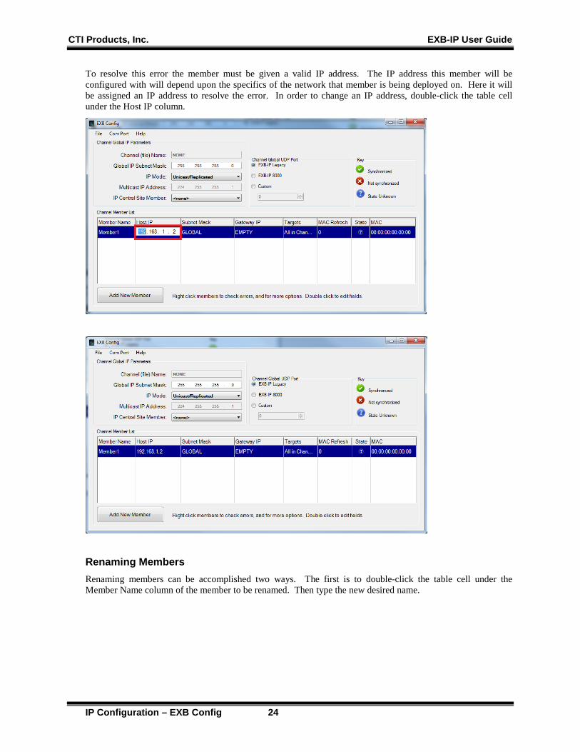
To resolve this error the member must be given a valid IP address. The IP address this member will be configured with will depend upon the specifics of the network that member is being deployed on. Here it will be assigned an IP address to resolve the error. In order to change an IP address, double-click the table cell under the Host IP column.
Renaming Members Renaming members can be accomplished two ways. The first is to double-click the table cell under the Member Name column of the member to be renamed. Then type the new desired name.
CTI Products, Inc. EXB-IP User Guide
IP Configuration – EXB Config 25
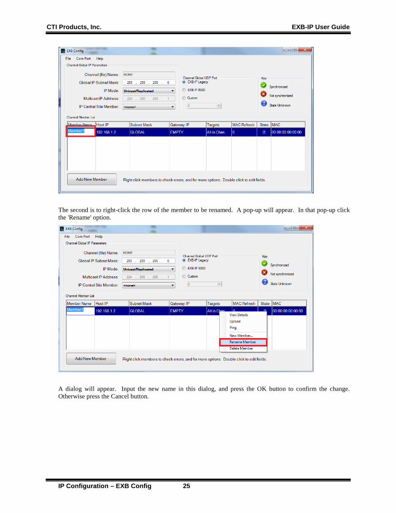
The second is to right-click the row of the member to be renamed. A pop-up will appear. In that pop-up click the 'Rename' option.
A dialog will appear. Input the new name in this dialog, and press the OK button to confirm the change. Otherwise press the Cancel button.
CTI Products, Inc. EXB-IP User Guide
IP Configuration – EXB Config 26
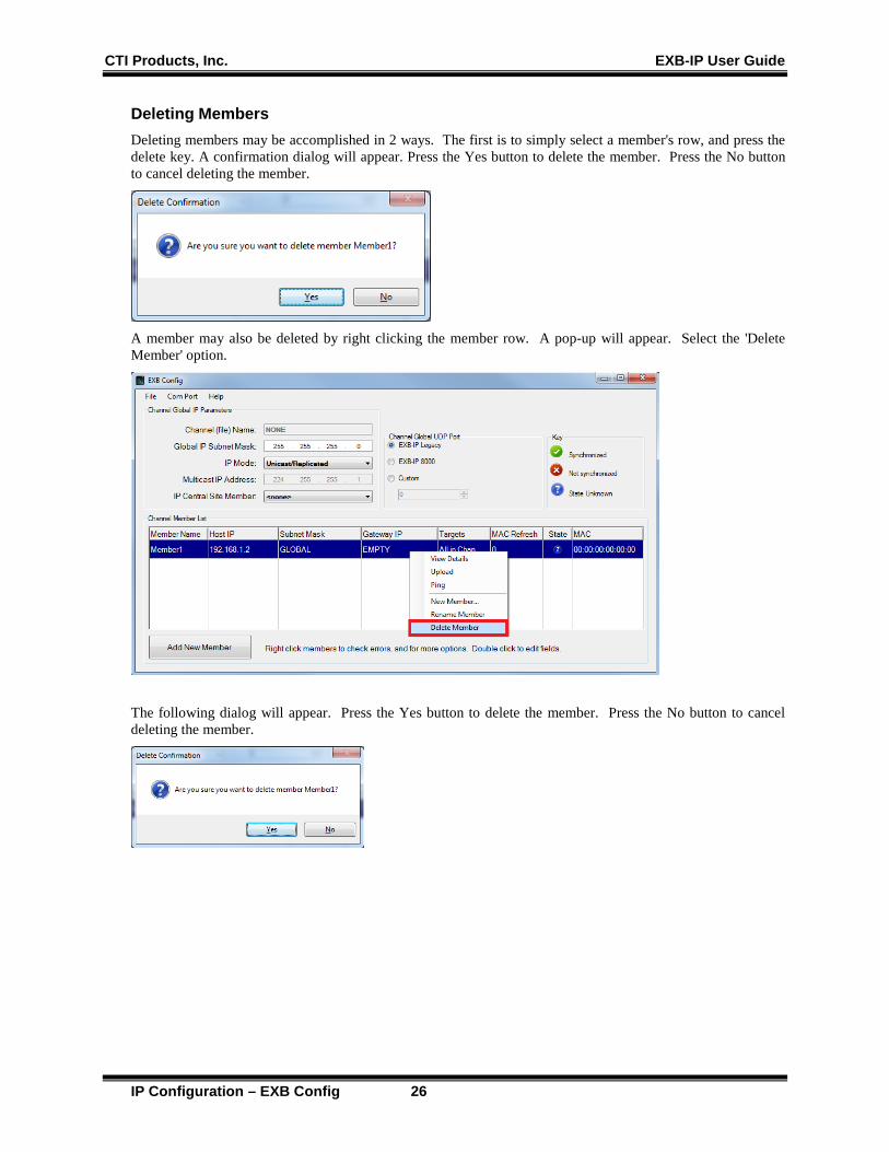
Deleting Members Deleting members may be accomplished in 2 ways. The first is to simply select a member's row, and press the delete key. A confirmation dialog will appear. Press the Yes button to delete the member. Press the No button to cancel deleting the member.
A member may also be deleted by right clicking the member row. A pop-up will appear. Select the 'Delete Member' option.
The following dialog will appear. Press the Yes button to delete the member. Press the No button to cancel deleting the member.
CTI Products, Inc. EXB-IP User Guide
IP Configuration – EXB Config 27
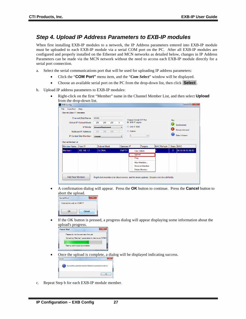
Step 4. Upload IP Address Parameters to EXB-IP modules When first installing EXB-IP modules to a network, the IP Address parameters entered into EXB-IP module must be uploaded to each EXB-IP module via a serial COM port on the PC. After all EXB-IP modules are configured and properly installed on the Ethernet and MCN networks as detailed below, changes in IP Address Parameters can be made via the MCN network without the need to access each EXB-IP module directly for a serial port connection.
a. Select the serial communications port that will be used for uploading IP address parameters: • Click the “COM Port” menu item, and the “Com Select” window will be displayed. • Choose an available serial port on the PC from the drop-down list, then click Select .
b. Upload IP address parameters to EXB-IP modules: • Right-click on the first “Member” name in the Channel Member List, and then select Upload
from the drop-down list.
• A confirmation dialog will appear. Press the OK button to continue. Press the Cancel button to
abort the upload.
• If the OK button is pressed, a progress dialog will appear displaying some information about the
upload's progress.
• Once the upload is complete, a dialog will be displayed indicating success.
c. Repeat Step b for each EXB-IP module member.
CTI Products, Inc. EXB-IP User Guide
IP Configuration – EXB Config 28
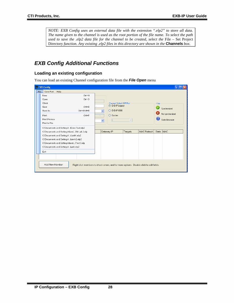
NOTE: EXB Config uses an external data file with the extension “.elp2” to store all data. The name given to the channel is used as the root portion of the file name. To select the path used to save the .elp2 data file for the channel to be created, select the File – Set Project Directory function. Any existing .elp2 files in this directory are shown in the Channels box.
EXB Config Additional Functions
Loading an existing configuration You can load an existing Channel configuration file from the File Open menu

CTI Products, Inc. EXB-IP User Guide
IP Configuration – EXB Config 29
Comparing Configurations / Viewing Configuration Data in a Module To verify that the configuration was uploaded successfully, right-click the member. A pop-up will appear. Select View Details from the drop-down list as shown below.
A confirmation dialog will appear. Press the OK button to continue. Press the Cancel button to abort viewing the details of the module.
If the OK button was pressed, a progress dialog will appear as shown below.

CTI Products, Inc. EXB-IP User Guide
IP Configuration – EXB Config 30
The following image shows a device which is configured properly. If any fields do not match, they will be highlighted in red, and the device will be marked as Not Synchronized.
Printing Information from the EXB Config Software To print Channel information, choose Print from the File menu of the Main window. To print Member information, choose Print from the File menu of the Detailed Member window as shown below.
You could also use the Print to File option.
CTI Products, Inc. EXB-IP User Guide
IP Configuration – EXB Config 31
BACKUP & RESTORE OPERATIONS The EXB Config software and the configuration files for the EXB-IP modules are not backed up as part of the ASTRO® 25 or any other system's Back UP & Restore (BAR) solution. Follow the Backup & Recovery procedures in this section for backing up and restoring these program files and configuration files.
The procedures in this section apply only to the EXB Config software and EXB-IP module configuration files, and do not back up or restore part of the ASTRO® 25 or any other system.
EXB Config Software Backup 1. If needed, use a commercially available method to make a backup copy of the
EXB Config distribution media (up to the limit of copies allowed by the license).
2. Store the original distribution media and the backup media in safe places.
EXB Config Software Restore 1. Locate either the original or backup copies of the EXB Config sioftware distribution media.
2. Re-install the EXB Config software as described in this manual.
EXB-IP module Configuration Files Backup Be sure to save the EXB-IP module configuration files whenever they are changed. The Custom EXB-IP module System Configuration Files are the files have been generated to describe your system. They include files with the following extension: • ChannelName.elp2 Where: ChannelName is the name you used when you saved your system and elp2 is the file extension. Note 1: If you have defined multiple channels, each one will have its own file.
1. Use Windows Explorer to find the current set of files that you are using for your system.
2. Use Windows Explorer or a commercially available method to make a backup copy of the files. (It may be helpful to use a program to Zip them up into a single file.)
3. Store the backup copy in safe places.
EXB-IP module Configuration Files Restore 1. Locate the backup of the EXB-IP module Configuration files.
2. Use Windows Explorer to copy those files to an appropriate directory on the PC that runs EXB Config software.

CTI Products, Inc. EXB-IP User Guide
IP Configuration – EXB Config 32
SECURITY AND INFORMATION ASSURANCE RECOMMENDATIONS Review these recommendations before installation and follow them during installation and operation:
1. Software Installation Locations Install the EXB Config software in default program directory recommended by Installshield.
2. Use the EXB-IP 8000 UDP ports for MSI RNIs as described in this manual.
3. For all software, network and device configuration, additionally take into consideration commercially accepted practices, industry standards and the standards for your organization.
4. Do not save user files or system configuration files in the program directory.
5. Save system configuration files to a directory that requires Administrator rights so that users cannot delete or edit the configuration files.
6. Always run the configuration software with the lowest permission set possible. Note: The EXB Config software must be run with Administrator rights.
7. When configuring a system, do not enter Sensitive or Confidential information into the system configuration files.
8. The configuration files generated by EXB Config Server are not backed up as part of the ASTRO® 25 Back UP & Restore (BAR) solution. Follow the Backup & Recovery procedures as listed in this manual.
9. Follow the applicable Backup & Recovery procedures for your system, PCs, and operating systems as defined by your organization, the hardware and software vendors, and commercially acceptable practices.
10. Limit access to PCs, IP networks, EXB-IP units and MCN networks, both physically and through appropriate restrictions in routers and switches
11. Use strong passwords where applicable.
12. Follow Motorola's and your organization's recommendations on security and Information Assurance.
13. Use the appropriate Windows Hardening Kits for PCs in your system.
14. Use anti-virus and anti-malware packages on PCs in your system.
15. Install appropriate security patches for installed software and operating system on PCs in your system.

CTI Products, Inc. EXB-IP User Guide
Hardware Installation 33
4. EXB-IP MODULE HARDWARE INSTALLATION INSTALL EXB-IP MODULES INTO THE IP NETWORK
A) Set the Option Switches: • Ensure that all OPTION switches are set appropriately for your system. The position of the
OPTION switches are read by the EXB-IP module at power-up or after pressing the “RESET” button on the front panel.
1 2 3 4 5 6 7 8 ON 1. Must be Up 2. HTTP Page Default Up Up = Enabled Down = Disabled 3. Not Used Default Up 4. Not Used Default Up 5. Not Used Default Up 6. Not Used Default Up 7. 8.
Ethernet Mode Switch: 7 8 10Base-T UP UP Ethernet Connector
B) Mount EXB-IP modules (See Appendix B for Mounting Option details): Desk, Wall, or Rack Mounting • Non-slip rubber feet are included on all EXB-IP modules to allow them to conveniently rest on any
horizontal surface. Four 6-32 threaded holes are also available on the bottom of the module to allow bolting of the module in any convenient orientation. WARNING: Care should be taken to limit protrusion of the screw into the module to no more than 0.125 inch from the module bottom surface!
• Mounting kits are available as options to allow wall or rack (19” EIA) mounting of the EXB modules.
C) Make electrical connections (See Appendix C for connector details):
Grounding • When wall or rack mounting the EXB, a suitable safety and protective earth ground should be
provided to the metal enclosure. The protective earth ground provides a path to ground for electrostatic discharge (ESD) energy. This connection is most conveniently made directly to the wall mount bracket or rack plate.
MCN Network Connection • The local MCN network must be attached to the EXB module via the “NETWORK” connector
following standard guidelines as to cable type, cable length, and termination appropriate for the selected transceiver. The dual RJ45 NETWORK connector allows a daisy-chained network
connection method, as the network pins of the two RJ45 connectors are directly paralleled. The EXB-IP module does not inject DC power on the network cable. It does not use any DC power from the cable. The 2 pin removable terminal strip is wired in parallel with the network connections on the dual RJ45
connector. This connector is normally not used.
NETWORK OUTIN

CTI Products, Inc. EXB-IP User Guide
Hardware Installation 34
Ethernet Connection
• The Ethernet network must be attached to the EXB-IP module via 10BaseT connector.
WARNING: DO NOT connect the EXB-IP modules to a live Ethernet network until they have been reconfigured with IP parameters supplied by the Network Administrator. Network-wide problems could arise from connecting devices to a network without coordination of addressing information.
The 10BaseT port utilizes a standard RJ45 connector. Cat 5 unshielded twisted pair cable should be used between the EXB-IP module and the hub. The length of this cable should be less than 100 meters (328 feet).
IP Switch Manual Settings Note Some IP Switches (Like some HP Switches) that have Auto Speed and Duplex negation may not be able to auto-negotiate with the EXB-IP module. In those cases, we recommend that you manually configure the Ethernet port in the IP switch that connects to the EXB-IP module. See the IP Switch Configuration – Speed & HDX/FDX Negotiation section on page 55 for more details.
DC Power Connection
DC power must be attached to the EXB-IP module via the DC IN connector. Apply DC power to the EXB-IP module only after all other connections have been made. A wall plug-in style power supply designed for the EXB-IP module is an available option.
The installation of the EXB-IP module is now complete.
10BASE-T
DC IN
CTI Products, Inc. EXB-IP User Guide
Hardware Installation 35
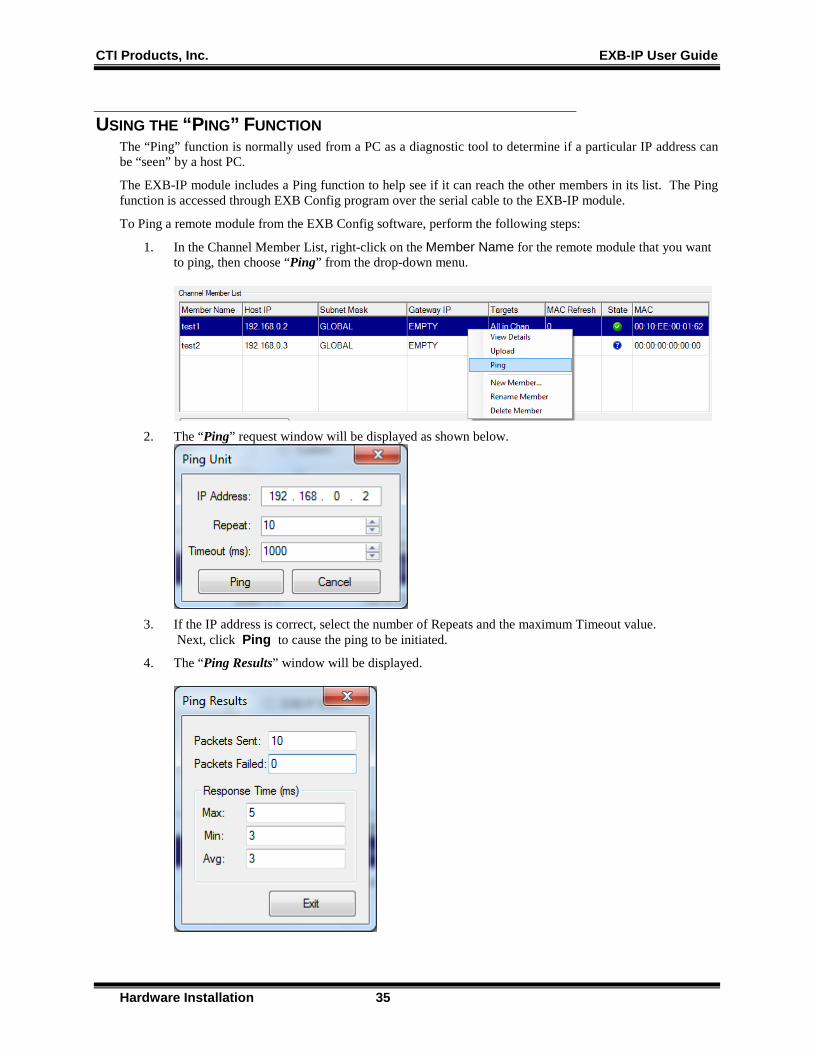
USING THE “PING” FUNCTION The “Ping” function is normally used from a PC as a diagnostic tool to determine if a particular IP address can be “seen” by a host PC.
The EXB-IP module includes a Ping function to help see if it can reach the other members in its list. The Ping function is accessed through EXB Config program over the serial cable to the EXB-IP module.
To Ping a remote module from the EXB Config software, perform the following steps:
1. In the Channel Member List, right-click on the Member Name for the remote module that you want to ping, then choose “Ping” from the drop-down menu.
2. The “Ping” request window will be displayed as shown below.
3. If the IP address is correct, select the number of Repeats and the maximum Timeout value.
Next, click Ping to cause the ping to be initiated.
4. The “Ping Results” window will be displayed.
CTI Products, Inc. EXB-IP User Guide
Hardware Installation 36
The response times may be a bit longer than you would normally expect due to the overhead of the serial communications and the communications through the local EXB-IP module.
You can also change the IP Address in Step 2 to ping other devices in the network like routers and smart switches.
INSTALLING ADDITIONAL EXB-IP MODULES AFTER INITIAL INSTALLATION If additional EXB-IP modules need to be installed after the initial installation has been completed, use one of the two following sequences:
If using Multicast IP Address Mode: 1. Start EXB Config and edit the IP Parameters for the new EXB-IP modules. 2. Upload IP Parameters to all new EXB-IP modules via the serial port. 3. Physically install all new EXB-IP modules into the IP Network per this INSTALLATION section.
If using Multicast IP Address Mode and All in Channel Target: 1. Start EXB Config and edit the IP Parameters for the new EXB-IP modules. 2. Upload IP Parameters to all new EXB-IP modules via the serial port. 3. Physically install all new EXB-IP modules into the IP Network per this INSTALLATION section. 4. Re-upload IP configuration parameters to all existing Channel members. This will add the IP
Addresses for the new modules to their member lists.
If using Unicast/Replicated IP Address Mode and Central Site Target: 1. Start EXB Config and edit the IP Parameters for the all new EXB-IP modules. 2. Upload IP Parameters to all new EXB-IP modules via the serial port. 3. Re-upload IP Parameters to the existing Central Site EXB-IP module via the serial port. 4. Physically install the new EXB-IP modules into the IP network per this INSTALLATION section starting
on Page 15. 5. If desired, re-upload IP Parameters to the other existing Channel members via the serial port. This will
put all EXB-IP modules in sync with the newly edited configuration data from Step 1 above.
CTI Products, Inc. EXB-IP User Guide
Glossary 37
5. GLOSSARY
EXB-IP module Network Extender Module used with CTI's MCN Networks to extend a network from one location to another over an IP channel
EXB-IP Legacy Module EXB-IP modules with a version number below 400. The Legacy modules used a fixed input UDP port of 1100 and did not support user-configurable UDP Port numbers. In the UDP Port field, EXB-IP Legacy is used to select the proper fixed port for communication between modules if there are any Legacy EXB-IP modules in the channel.
EXB-IP Legacy Port A destination UDP Port of 1100 as used by Legacy EXB-IP modules. EXB-IP 8000 modules can also be configured to use this Port to communicate with legacy EXB-IP modules.
EXB-IP 8000 Module EXB-IP modules with a version number of 400 and above. These modules used a user-configurable input UDP port. In Motorola Solutions, Inc. Astro25™ networks ( 7.13 and above), a fixed UDP port has been reserved for the EXB-IP modules for communication across the Radio Network Infrastructure (RNI). This UDP port is used when EXB-IP 8000 is selected in the UDP Port field. The EXB-IP 8000 setting cannot be used if there any Legacy EXB-IP modules in the channel.
EXB-IP 8000 Port A destination UDP Port compatible with Motorola Solutions, Inc. Astro™25 Radio Network Infrastructure version 7.13 and above.
Channel In general, the "Channel" is used in this manual to indicate all the EXB-IP modules that will communicate with each other, along with the IP network (LANs and WAN) connecting those modules.
Com Port Synonymous with RS-232 port
Gateway If EXB-IP modules reside on a different IP Subnets, they must communicate through IP routers. The Gateway is the IP address of the port of the router closest to the EXB-IP module. The Gateway Address associated with a member EXB-IP module must be in the same subnet as that EXB-IP module.
IP Internet Protocol.. IP Version 4 is used by the EXB-IP modules.
IP address Logical network address used for IP communication in an IPV4 network. In the EXB Config program it is specified as four octets (ex: 192.168.2.7).
IPV4 Internet Protocol Version 4
I/O Input and output.
MCN™ CTI Products' Monitoring and Control Network
Member One of the EXB-IP modules in a Channel
CTI Products, Inc. EXB-IP User Guide
Glossary 38
Multicast A method of communicating in which all devices join (and listen to) a common (IP Multicast) group. A transmitting device will need to send messages to a single destination (the Multicast address) to send a message to all modules. This reduces loading on the EXB-IP modules and bandwidth required on the network.
Multicast IP Address An IP address in the range of 224.0.0.1 to 239.255.255.254 used for information broadcasts to registered computers. Many networks will have filters configured on routers and firewalls to pass or reject traffic to specific Multicast IP addresses or ranges.
RS-232 Port 9 pin serial port
Subnet A subnet is the range of addresses which a device can communicate directly without having to go through a router. A subnet is defined by an IP address and a subnet mask.
Subnet mask A 32 bit number typically formatted as an IP address, used with an IP address in defining a subnet. When converted to binary, any of the 1's in the Subnet Mask indicate the Subnet for a particular IP address. Target The EXB-IP module(s) to which a particular member EXB-IP module communicates. EXB-IP modules can be configured to communicate either with all modules or just a central member.
UDP User Datagram Protocol
UDP Port A number used by the UDP protocol to indicate the source or destination within a device that uses UDP protocol. Devices will send from their Source Port and will listen on their Destination Port. Many systems will have routers and firewalls configured to pass or reject packets based on the Source and/or Destination ports.
CTI Products, Inc. EXB-IP User Guide
Appendix A - Factory Default Configuration 39
6. APPENDIX APPENDIX A. FACTORY DEFAULT CONFIGURATION
Control Processor
Restoring Factory Default Communication Parameters If the Control Processor or router module communication parameters are overwritten by a network management tool, they can be restored as follows:
• Press the “RESET” button on the front of the EXB-IP module • After the “ERR” LED goes off, press the “RESET” button a second time.
The Control Processor communication parameters are now restored to factory defaults.
IP Address Parameters The modules are factory programmed as follows:
• IP Address: Unique address based on MAC address of module • IP Address Mode: Multicast • IP Multicast Address: 224.0.1.16 • Subnet Mask: 255.255.255.0
MCN Router For custom-configured systems, the MCN router portion of the EXB-IP module may be configured for various operational characteristics. The factory default configuration is as a repeater, where all messages entering the EXB-IP module via the MCN Network or the Ethernet network are simply passed through. Other configurations may be set in custom configured systems. If so, that information will be provided with those systems.
Using SETRTR2.EXE to Query or Change Router Configuration
SETRTR Caution:
There was an original utility called "SETRTR.EXE". It should not be used with EXB-IP or EXB-IP units shipped in 2012 or after. If it is used it will cause permanent damage to the internal router.
A new SWTRTR2.EXE utility started shipping in August, 2012. It is safe for use with all version EXB-IP units and EXB-IP 8000 units.
*Note: SETRTR2 is a 16-Bit application. It will work with Windows XP. It will not work with Windows Vista, 7, Server 2008 or above.
The SETRTR2.EXE DOS utility provided with each EXB can be used to query the router for its current configuration, force the router to certain default states, or force the router to unconfigured mode. If the router will be installed with the configured router algorithm, it is highly recommended that the router module is set to unconfigured mode before being installed into the system (this step is mandatory if redundant routers are to be configured).
The SETRTR2 program requires a network interface to be connected to the host PC with a PCLTA interface. Network interface driver software must be loaded in the host PC and configured with a device name (typically "LONn" where n is a number). Documentation that is provided with the network interface device details how to
CTI Products, Inc. EXB-IP User Guide
Appendix A - Factory Default Configuration 40
install the module and driver software. The network interface device must contain a network transceiver compatible with the network transceiver in the EXB module to be controlled (78K or 1250).
After the network interface and its software driver are properly configured on the host PC, connect its network port to the front panel “NETWORK” connector on the EXB.
Querying an EXB’s Router for its Current Configuration
Start the SETRTR2 program with the following command line: SETRTR2 [-ddevicename] -L <cr>
where devicename is the name assigned to the network interface on the command line of the device driver (typically "LON1" or "LON2"). If this parameter is omitted, the default name of LON1 is used.
The -L parameter instructs SETRTR2 to List the current configuration of the router module.
After the signon message appears, press the “RSVC” button on the front of the connected EXB module. SETRTR2 will report the current router configuration to the screen.
Returning an EXB’s Router to Factory Default Configuration
Start the SETRTR2 program with the following command line: SETRTR2 [-ddevicename] -F <cr>
where devicename is the name assigned to the network interface on the command line of the device driver (typically "LON1" or "LON2"). If this parameter is omitted, the default name of LON1 is used.
The -F parameter instructs SETRTR2 to set the EXB's router to Factory defaults.
After the sign-on message appears, press the “RSVC” button on the front of the connected EXB module. SETRTR2 will send the required messages to the router and exit. Press the “RESET” button on the front of the EXB module to complete the reconfiguration.
Note: If you are using a Custom Configured EXB, you will need to reconfigure the EXB as described in the Custom Configuration data shipped with the system.
Setting an EXB’s Router to Unconfigured Mode
Start the SETRTR2 program with the following command line: SETRTR2 [-ddevicename] -U <cr>
The -U parameter instructs SETRTR2 to set both sides of the EXB’s router to Unconfigured mode.
After the signon message appears, press the “RSVC” button on the front of the connected EXB module. SETRTR2 will send the required messages to the router and exit.
CTI Products, Inc. EXB-IP User Guide
Appendix B – Mounting Options 41
APPENDIX B. MOUNTING OPTIONS Wall mount and EIA 19” rack mount kits are available as options for the EXB from CTI Products, Inc. The wall mount kit includes brackets to allow a single EXB module to be mounted to any flat surface. The rack mount kit includes an adapter allowing up to three EXB modules to be mounted in a single rack unit height.
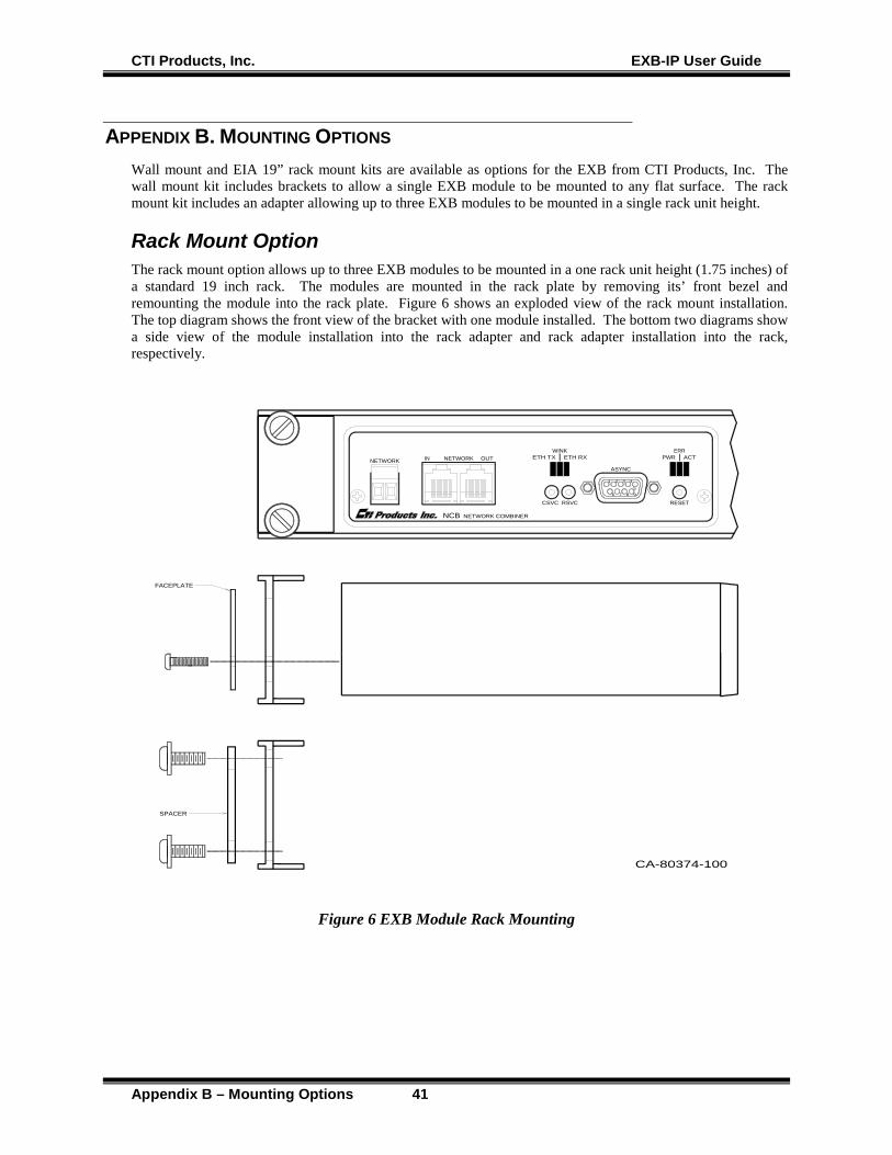
Rack Mount Option The rack mount option allows up to three EXB modules to be mounted in a one rack unit height (1.75 inches) of a standard 19 inch rack. The modules are mounted in the rack plate by removing its’ front bezel and remounting the module into the rack plate. Figure 6 shows an exploded view of the rack mount installation. The top diagram shows the front view of the bracket with one module installed. The bottom two diagrams show a side view of the module installation into the rack adapter and rack adapter installation into the rack, respectively.
CA-80374-100
FACEPLATE
SPACER
1 2 3 4
59876
ERRACTPWR
RESET
WINKETH RXETH TX
CSVC RSVC
NETWORK OUTIN
ASYNCNETWORK
NCB NETWORK COMBINER
Figure 6 EXB Module Rack Mounting

CTI Products, Inc. EXB-IP User Guide
Appendix B – Mounting Options 42
To attach a module to the rack adapter, and then mount the rack adapter into the rack, follow the steps below.
WARNING
Do not allow the PC board to slide out of the housing when the front panel is removed. If it does, DO NOT slide the PC board back into the housing from the front of the module. Doing so may damage the module, causing the module to malfunction when powered on. Doing so will void the module’s warranty. Return the PC board to the housing by sliding it only from the rear. (See instructions below.)
Rack Mounting Instructions
Step Operation 1 Remove the front panel from the module, including the bezel, by removing the two
Philips head screws in the faceplate. The bezel is not used when rack mounting the module.
2 Position the module behind the rack adapter, lining up the holes in the rack adapter with the front panel screw holes on the module.
3 Position the front panel in front of the rack adapter, lining up the front panel with the module.
4 Fasten the front panel and module to the rack adapter with the Philips head screws that were previously removed.
5 Position the rack adapter into your rack, lining up the four mounting holes of the rack adapter with mounting holes in the rack frame.
6 Position the two spacers in the front of the rack adapter, aligning the cutouts in the spacers with the holes of the adapter.
7 Install mounting screws (customer provided) into the rack.
When the module’s front panel is removed, do not allow the PC board to slide out of the housing. If the PC board does slide out of the housing, you must follow the steps below to replace the PC board in the housing. DO NOT RE-INSTALL THE PC BOARD FROM THE FRONT OF THE HOUSING !
Re-Installing a PC Board in its housing
Step Operation 1 From the front of the module, slide the PC board out of the housing. 2 Remove the back panel of the module. 3 Attach either bezel and front panel or rack kit and front panel to the housing with two
Philips head screws. 3 From the rear of the module, slide the PC board back into the housing (there are
markings on the PC board to indicate which edge to insert into the rear of the housing first).
4 Attach bezel and rear panel to the housing with two Philips head screws.
CTI Products, Inc. EXB-IP User Guide
Appendix B – Mounting Options 43
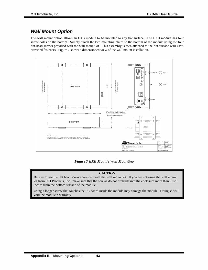
Wall Mount Option The wall mount option allows an EXB module to be mounted to any flat surface. The EXB module has four screw holes on the bottom. Simply attach the two mounting plates to the bottom of the module using the four flat-head screws provided with the wall mount kit. This assembly is then attached to the flat surface with user-provided fasteners. Figure 7 shows a dimensioned view of the wall mount installation.
IndustryCanada
NOTE:THE NUMBERS ON THIS DRAWING REFER TO THE ITEM NUMBERSON THE CORRESPONDING BILLS OF MATERIAL FOR THIS ASSEMBLY.
24 VDC100 mA
BOTTOM VIEW
USE ONLY 6-32 X 1/4" LONGFLAT HEAD SCREWS TO ATTACH THEWALL MOUNT BRACKET TO THIS UNIT.
TO PREVENT DAMAGE TO THE CIRCUIT BOARD. CAUTION!
USE ONLY 6-32 X 1/4" LONGFLAT HEAD SCREWS TO ATTACH THE
WALL MOUNT BRACKET TO THIS UNIT.
TO PREVENT DAMAGE TO THE CIRCUIT BOARD.CAUTION!
Products Inc.
ETL APPRO
3.500 1.980
6.13
0
6.70
01.
642
TOP VIEW1
2
Provided by installer.
Allo
w ro
om o
n en
dsfo
r con
nect
ors.
Allo
w ro
om o
n en
dsfo
r con
nect
ors.
SIDE VIEW
1.980
QTY 2
QTY 4
QTY 4 NO. 8 SCREWS OR OTHERAPPROPRIATE HARDWARE.
OR
OR
DRAWN BY
APPROVED BYSCALE
DATE
DATE
SHEET OF
TITLE
DRAWING NUMBER
1 1
NONEAPPLICATION
CFA11-22-96
11-22-96
WON PRODUCTS
RKKWON NCB SIZE "B" WALL MOUNT KIT
12
34
56
78
ON
OP
TIO
N A
DC
IN
ERR A
CT
PW
R
RS
VC
CS
VCAU
DIO
LIN
EC
DO
H
RE
SE
TC
MD
NC
BN
ET
WO
RK
CO
MB
INE
R
NE
TWO
RK
Figure 7 EXB Module Wall Mounting
CAUTION Be sure to use the flat head screws provided with the wall mount kit. If you are not using the wall mount kit from CTI Products, Inc., make sure that the screws do not protrude into the enclosure more than 0.125 inches from the bottom surface of the module. Using a longer screw that touches the PC board inside the module may damage the module. Doing so will void the module’s warranty.
CTI Products, Inc. EXB-IP User Guide
Appendix C - Connector Details 44
APPENDIX C. CONNECTOR DETAILS
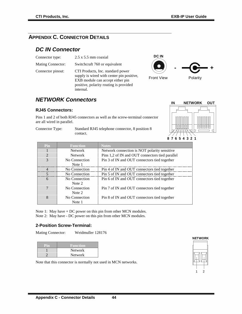
DC IN Connector Connector type: 2.5 x 5.5 mm coaxial
Mating Connector: Switchcraft 760 or equivalent
Connector pinout: CTI Products, Inc. standard power supply is wired with center pin positive, EXB module can accept either pin positive, polarity routing is provided internal.
NETWORK Connectors
RJ45 Connectors: Pins 1 and 2 of both RJ45 connectors as well as the screw-terminal connector are all wired in parallel.
Connector Type: Standard RJ45 telephone connector, 8 position 8 contact.
Pin Function Notes 1 Network Network connection is NOT polarity sensitive 2 Network Pins 1,2 of IN and OUT connectors tied parallel 3 No Connection
Note 1 Pin 3 of IN and OUT connectors tied together
4 No Connection Pin 4 of IN and OUT connectors tied together 5 No Connection Pin 5 of IN and OUT connectors tied together 6 No Connection
Note 2 Pin 6 of IN and OUT connectors tied together
7 No Connection Note 2
Pin 7 of IN and OUT connectors tied together
8 No Connection Note 1
Pin 8 of IN and OUT connectors tied together
Note 1: May have + DC power on this pin from other MCN modules. Note 2: May have - DC power on this pin from other MCN modules.
2-Position Screw-Terminal: Mating Connector: Weidmuller 128176
Pin Function 1 Network 2 Network
Note that this connector is normally not used in MCN networks.
+-Polarity
DC IN
Front View
NETWORK OUTIN
12345678
NETWORK
1 2
CTI Products, Inc. EXB-IP User Guide
Appendix C - Connector Details 45
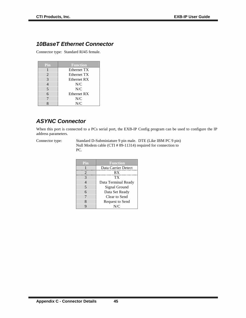
10BaseT Ethernet Connector Connector type: Standard RJ45 female.
Pin Function 1 Ethernet TX 2 Ethernet TX 3 Ethernet RX 4 N/C 5 N/C 6 Ethernet RX 7 N/C 8 N/C
ASYNC Connector When this port is connected to a PCs serial port, the EXB-IP Config program can be used to configure the IP address parameters.
Connector type: Standard D-Subminiature 9 pin male. DTE (Like IBM PC 9 pin) Null Modem cable (CTI # 89-11314) required for connection to PC.
Pin Function 1 Data Carrier Detect 2 RX 3 TX 4 Data Terminal Ready 5 Signal Ground 6 Data Set Ready 7 Clear to Send 8 Request to Send 9 N/C

CTI Products, Inc. EXB-IP User Guide
Appendix D. EXB-IP Programming Cable 46
APPENDIX D. EXB-IP PROGRAMMING CABLE PINOUT 89-11314
Pin Function Function Pin 1 DCD
Data Carrier Detect DCD
Data Carrier Detect 1
2 RXD
RXD 2
3 TXD
TXD 3
4 DTR Data Terminal Ready
DTR Data Terminal Ready
4
5 GND Signal Ground
GND Signal Ground
5
6 DSR Data Set Ready
DSR Data Set Ready
6
7 CTS Clear to Send
CTS Clear to Send
7
8 RTS Request to Send
RTS Request to Send
8
N/C N/C 9
Programming Cable Warning Always use the proper cable. If an improper cable is used, the EXB Config software might not be able to consistently View or Upload the data to the EXB-IP unit.

CTI Products, Inc. EXB-IP User Guide
Appendix E - Troubleshooting 47
APPENDIX E. TROUBLESHOOTING
Table E1 If the PWR LED . . . REASON CORRECTIVE ACTION Is always illuminated. Normal operation indicating that EXB
module is receiving proper DC input power.
Go to next Table.
Does not illuminate. EXB module is not receiving DC input power.
Check for proper voltage at “DC IN” connector (10-32VDC).
Table E2 If the ERR LED . . . REASON CORRECTIVE ACTION Is always off. Normal operation indicating no error
condition was detected. Go to next Table.
Occasionally blinks on, then off.
Normal operation when “CSVC” button or “RSVC” button is pressed.
Go to next Table.
Flashes slowly, at a rate of once every 2 seconds.
The Router Neurons are unconfigured. Use LonScrpt or NODEUTIL to change the mode/state to ‘Configured’ and ‘On-line’, or Use SETRTR2 –F to configure the router to Factory default conditions (Repeater Mode).
Flashes quickly, at a rate of once every second.
The Control Neuron Processor detects missing IP address information.
Use EXB-IP Config to update the IP address parameters. (See Installation section for instructions.)
Is always illuminated. Router module, or Control Neuron Processor, or Microprocessor is not functioning.
Call CTI Products, Customer Support (+1-513-595-5900), to arrange to return module for evaluation/repair.
Table E3 If the ETH TX LED (on
local EXB-IP module) . . .
REASON CORRECTIVE ACTION
Occasionally blinks on, then off.
Normal operation indicating a message packet has been transmitted from the Ethernet port.
Go to next Table.
Does not illuminate when “RSVC” button on local EXB-IP module is pressed.
Ethernet port is not terminated correctly to the IP network.
a. Verify that OPTION switch positions 7 and 8 are set correctly for the Ethernet connector being used. See INSTALLATION section.
b. Verify that the cable from EXB-IP module Ethernet port is terminated correctly to IP network. Check the ‘connection’ LED that is found near each port on most IP interconnect devices.
c. Verify that the correct cross or straight-through cable is being used. See “Appendix F. IP Addresses”.

CTI Products, Inc. EXB-IP User Guide
Appendix E - Troubleshooting 48
Table E4 If the ETH RX LED (on
local EXB-IP module) . . .
REASON CORRECTIVE ACTION
Occasionally blinks on, then off.
Normal operation indicating a message packet has been detected on the IP network.
Go to next Table.
Does not illuminate when “RSVC” button on remote EXB-IP module is pressed.
1. Ethernet port is not terminated correctly to the IP network.
2. If Unicast/Replicated addressing mode is being used, IP addresses for local and remote EXB-IP module are not compatible.
3. If Multicast addressing mode is being used, IP network routers or switches are not configured properly.
1a. Verify that OPTION switch positions 7 and 8 are set correctly for the Ethernet connector being used. See INSTALLATION section.
b. Verify that the cable from EXB-IP module Ethernet port is terminated correctly to IP network. Check the ‘connection’ LED that is found near each port on most IP interconnect devices.
c. Verify that the correct cross or straight-through cable is being used. See “Appendix F. IP Addresses”.
2a. Verify that portion of IP addresses identified by Subnet Mask for both local and remote EXB-IP modules are identical.
3a. Verify that IP routers and switches have Multicast mode enabled.
b. Verify that IP routers are programmed to pass the IP multicast address of the EXB-IP module.
c. Verify that IP routers are programmed to pass the proper destination (configurable) and source (1283) UDP Port numbers used by the EXB-IP modules in the channel.
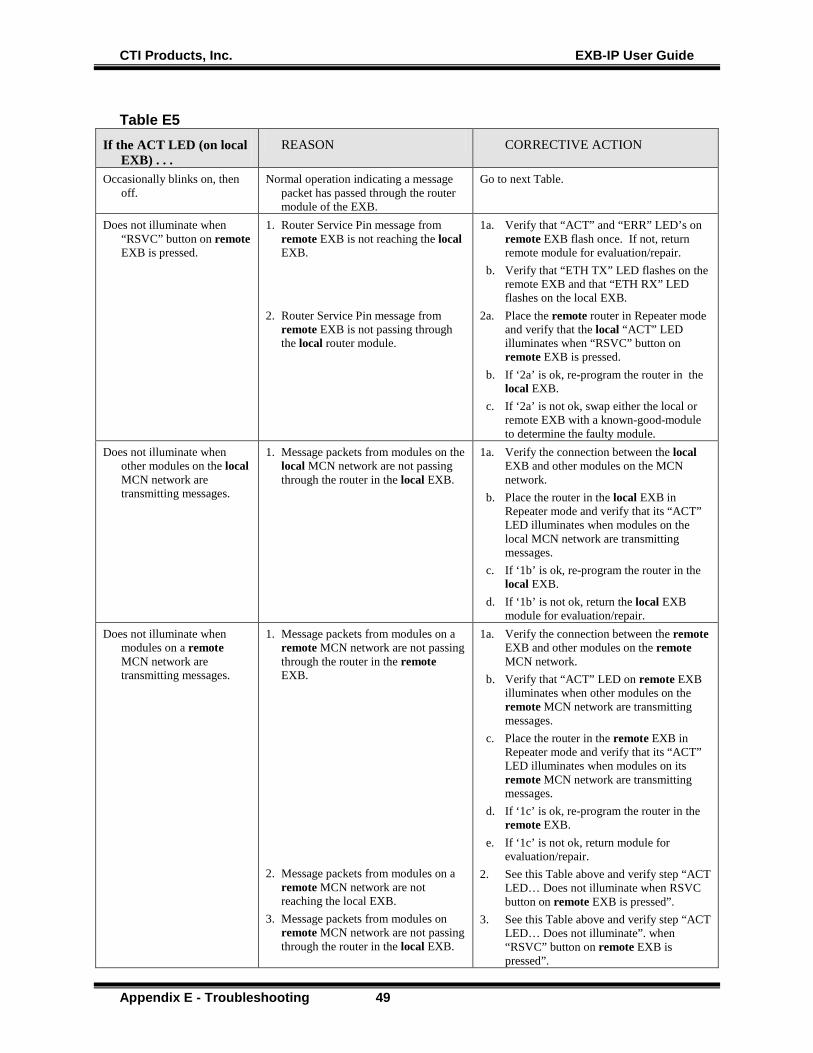
CTI Products, Inc. EXB-IP User Guide
Appendix E - Troubleshooting 49
Table E5 If the ACT LED (on local
EXB) . . . REASON CORRECTIVE ACTION
Occasionally blinks on, then off.
Normal operation indicating a message packet has passed through the router module of the EXB.
Go to next Table.
Does not illuminate when “RSVC” button on remote EXB is pressed.
1. Router Service Pin message from remote EXB is not reaching the local EXB.
2. Router Service Pin message from remote EXB is not passing through the local router module.
1a. Verify that “ACT” and “ERR” LED’s on remote EXB flash once. If not, return remote module for evaluation/repair.
b. Verify that “ETH TX” LED flashes on the remote EXB and that “ETH RX” LED flashes on the local EXB.
2a. Place the remote router in Repeater mode and verify that the local “ACT” LED illuminates when “RSVC” button on remote EXB is pressed.
b. If ‘2a’ is ok, re-program the router in the local EXB.
c. If ‘2a’ is not ok, swap either the local or remote EXB with a known-good-module to determine the faulty module.
Does not illuminate when other modules on the local MCN network are transmitting messages.
1. Message packets from modules on the local MCN network are not passing through the router in the local EXB.
1a. Verify the connection between the local EXB and other modules on the MCN network.
b. Place the router in the local EXB in Repeater mode and verify that its “ACT” LED illuminates when modules on the local MCN network are transmitting messages.
c. If ‘1b’ is ok, re-program the router in the local EXB.
d. If ‘1b’ is not ok, return the local EXB module for evaluation/repair.
Does not illuminate when modules on a remote MCN network are transmitting messages.
1. Message packets from modules on a remote MCN network are not passing through the router in the remote EXB.
2. Message packets from modules on a
remote MCN network are not reaching the local EXB.
3. Message packets from modules on remote MCN network are not passing through the router in the local EXB.
1a. Verify the connection between the remote EXB and other modules on the remote MCN network.
b. Verify that “ACT” LED on remote EXB illuminates when other modules on the remote MCN network are transmitting messages.
c. Place the router in the remote EXB in Repeater mode and verify that its “ACT” LED illuminates when modules on its remote MCN network are transmitting messages.
d. If ‘1c’ is ok, re-program the router in the remote EXB.
e. If ‘1c’ is not ok, return module for evaluation/repair.
2. See this Table above and verify step “ACT LED… Does not illuminate when RSVC button on remote EXB is pressed”.
3. See this Table above and verify step “ACT LED… Does not illuminate”. when “RSVC” button on remote EXB is pressed”.
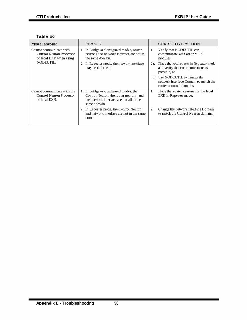
CTI Products, Inc. EXB-IP User Guide
Appendix E - Troubleshooting 50
Table E6 Miscellaneous: REASON CORRECTIVE ACTION Cannot communicate with
Control Neuron Processor of local EXB when using NODEUTIL.
1. In Bridge or Configured modes, router neurons and network interface are not in the same domain.
2. In Repeater mode, the network interface may be defective.
1. Verify that NODEUTIL can communicate with other MCN modules.
2a. Place the local router in Repeater mode and verify that communications is possible, or
b. Use NODEUTIL to change the network interface Domain to match the router neurons’ domains.
Cannot communicate with the Control Neuron Processor of local EXB.
1. In Bridge or Configured modes, the Control Neuron, the router neurons, and the network interface are not all in the same domain.
2. In Repeater mode, the Control Neuron and network interface are not in the same domain.
1. Place the router neurons for the local EXB in Repeater mode.
2. Change the network interface Domain to match the Control Neuron domain.
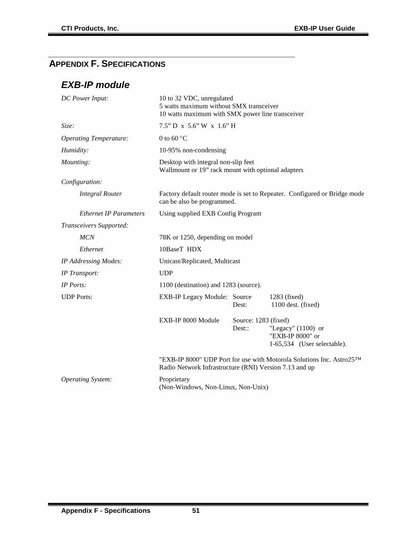
CTI Products, Inc. EXB-IP User Guide
Appendix F - Specifications 51
APPENDIX F. SPECIFICATIONS
EXB-IP module DC Power Input: 10 to 32 VDC, unregulated
5 watts maximum without SMX transceiver 10 watts maximum with SMX power line transceiver
Size: 7.5” D x 5.6” W x 1.6” H
Operating Temperature: 0 to 60 °C
Humidity: 10-95% non-condensing
Mounting: Desktop with integral non-slip feet Wallmount or 19” rack mount with optional adapters
Configuration:
Integral Router Factory default router mode is set to Repeater. Configured or Bridge mode can be also be programmed.
Ethernet IP Parameters Using supplied EXB Config Program
Transceivers Supported:
MCN 78K or 1250, depending on model
Ethernet 10BaseT HDX
IP Addressing Modes: Unicast/Replicated, Multicast
IP Transport: UDP
IP Ports: 1100 (destination) and 1283 (source).
UDP Ports: EXB-IP Legacy Module: Source 1283 (fixed) Dest: 1100 dest. (fixed) EXB-IP 8000 Module Source: 1283 (fixed) Dest:: "Legacy" (1100) or "EXB-IP 8000" or 1-65,534 (User selectable). "EXB-IP 8000" UDP Port for use with Motorola Solutions Inc. Astro25™ Radio Network Infrastructure (RNI) Version 7.13 and up
Operating System: Proprietary (Non-Windows, Non-Linux, Non-Unix)
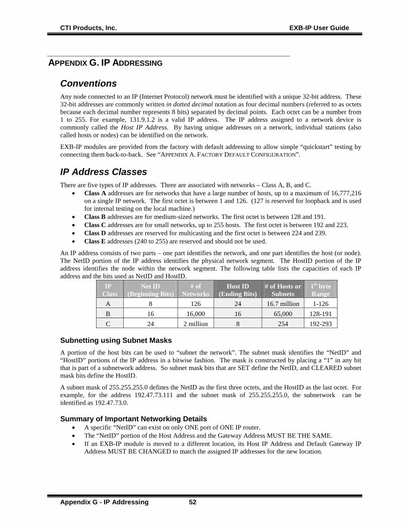
CTI Products, Inc. EXB-IP User Guide
Appendix G - IP Addressing 52
APPENDIX G. IP ADDRESSING
Conventions Any node connected to an IP (Internet Protocol) network must be identified with a unique 32-bit address. These 32-bit addresses are commonly written in dotted decimal notation as four decimal numbers (referred to as octets because each decimal number represents 8 bits) separated by decimal points. Each octet can be a number from 1 to 255. For example, 131.9.1.2 is a valid IP address. The IP address assigned to a network device is commonly called the Host IP Address. By having unique addresses on a network, individual stations (also called hosts or nodes) can be identified on the network.
EXB-IP modules are provided from the factory with default addressing to allow simple “quickstart” testing by connecting them back-to-back. See “APPENDIX A. FACTORY DEFAULT CONFIGURATION”.
IP Address Classes There are five types of IP addresses. Three are associated with networks – Class A, B, and C.
• Class A addresses are for networks that have a large number of hosts, up to a maximum of 16,777,216 on a single IP network. The first octet is between 1 and 126. (127 is reserved for loopback and is used for internal testing on the local machine.)
• Class B addresses are for medium-sized networks. The first octet is between 128 and 191. • Class C addresses are for small networks, up to 255 hosts. The first octet is between 192 and 223. • Class D addresses are reserved for multicasting and the first octet is between 224 and 239. • Class E addresses (240 to 255) are reserved and should not be used.
An IP address consists of two parts – one part identifies the network, and one part identifies the host (or node). The NetID portion of the IP address identifies the physical network segment. The HostID portion of the IP address identifies the node within the network segment. The following table lists the capacities of each IP address and the bits used as NetID and HostID.
IP Class
Net ID (Beginning Bits)
# of Networks
Host ID (Ending Bits)
# of Hosts or Subnets
1st byte Range
A 8 126 24 16.7 million 1-126 B 16 16,000 16 65,000 128-191 C 24 2 million 8 254 192-293
Subnetting using Subnet Masks A portion of the host bits can be used to “subnet the network”. The subnet mask identifies the “NetID” and “HostID” portions of the IP address in a bitwise fashion. The mask is constructed by placing a “1” in any bit that is part of a subnetwork address. So subnet mask bits that are SET define the NetID, and CLEARED subnet mask bits define the HostID.
A subnet mask of 255.255.255.0 defines the NetID as the first three octets, and the HostID as the last octet. For example, for the address 192.47.73.111 and the subnet mask of 255.255.255.0, the subnetwork can be identified as 192.47.73.0.
Summary of Important Networking Details • A specific “NetID” can exist on only ONE port of ONE IP router. • The “NetID” portion of the Host Address and the Gateway Address MUST BE THE SAME. • If an EXB-IP module is moved to a different location, its Host IP Address and Default Gateway IP
Address MUST BE CHANGED to match the assigned IP addresses for the new location.
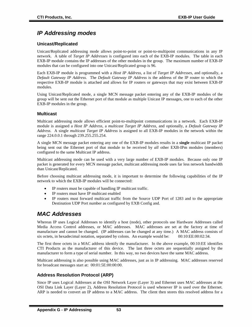
CTI Products, Inc. EXB-IP User Guide
Appendix G - IP Addressing 53
IP Addressing modes
Unicast/Replicated Unicast/Replicated addressing mode allows point-to-point or point-to-multipoint communications in any IP network. A table of Target IP Addresses is configured into each of the EXB-IP modules. The table in each EXB-IP module contains the IP addresses of the other modules in the group. The maximum number of EXB-IP modules that can be configured into one Unicast/Replicated group is 96.
Each EXB-IP module is programmed with a Host IP Address, a list of Target IP Addresses, and optionally, a Default Gateway IP Address. The Default Gateway IP Address is the address of the IP router to which the respective EXB-IP module is attached and allows for IP routers or gateways that may exist between EXB-IP modules.
Using Unicast/Replicated mode, a single MCN message packet entering any of the EXB-IP modules of the group will be sent out the Ethernet port of that module as multiple Unicast IP messages, one to each of the other EXB-IP modules in the group.
Multicast Multicast addressing mode allows efficient point-to-multipoint communications in a network. Each EXB-IP module is assigned a Host IP Address, a multicast Target IP Address, and optionally, a Default Gateway IP Address. A single multicast Target IP Address is assigned to all EXB-IP modules in the network within the range 224.0.0.1 through 239.255.255.254.
A single MCN message packet entering any one of the EXB-IP modules results in a single multicast IP packet being sent out the Ethernet port of that module to be received by all other EXB-IPm modules (members) configured to the same Multicast IP address.
Multicast addressing mode can be used with a very large number of EXB-IP modules. Because only one IP packet is generated for every MCN message packet, multicast addressing mode uses far less network bandwidth than Unicast/Replicated.
Before choosing multicast addressing mode, it is important to determine the following capabilities of the IP network to which the EXB-IP modules will be connected:
• IP routers must be capable of handling IP multicast traffic. • IP routers must have IP multicast enabled • IP routers must forward multicast traffic from the Source UDP Port of 1283 and to the appropriate
Destination UDP Port number as configured by EXB Config and.
MAC Addresses Whereas IP uses Logical Addresses to identify a host (node), other protocols use Hardware Addresses called Media Access Control addresses, or MAC addresses. MAC addresses are set at the factory at time of manufacture and cannot be changed. (IP addresses can be changed at any time.) A MAC address consists of six octets, in hexadecimal notation, separated by colons. An example would be: 00:10:EE:00:02:34.
The first three octets in a MAC address identify the manufacturer. In the above example, 00:10:EE identifies CTI Products as the manufacturer of this device. The last three octets are sequentially assigned by the manufacturer to form a type of serial number. In this way, no two devices have the same MAC address.
Multicast addressing is also possible using MAC addresses, just as in IP addressing. MAC addresses reserved for broadcast messages start at: 00:01:5E:00:00:00.
Address Resolution Protocol (ARP) Since IP uses Logical Addresses at the OSI Network Layer (Layer 3) and Ethernet uses MAC addresses at the OSI Data Link Layer (Layer 2), Address Resolution Protocol is used whenever IP is used over the Ethernet. ARP is needed to convert an IP address to a MAC address. The client then stores this resolved address for a
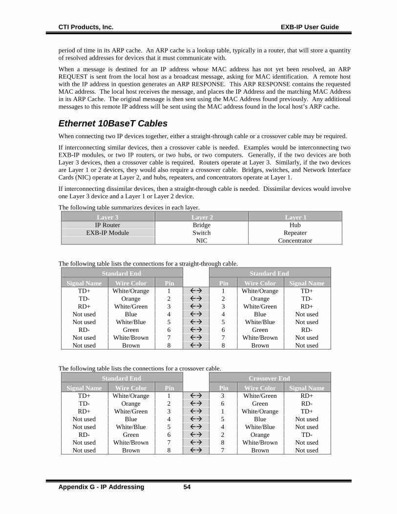
CTI Products, Inc. EXB-IP User Guide
Appendix G - IP Addressing 54
period of time in its ARP cache. An ARP cache is a lookup table, typically in a router, that will store a quantity of resolved addresses for devices that it must communicate with.
When a message is destined for an IP address whose MAC address has not yet been resolved, an ARP REQUEST is sent from the local host as a broadcast message, asking for MAC identification. A remote host with the IP address in question generates an ARP RESPONSE. This ARP RESPONSE contains the requested MAC address. The local host receives the message, and places the IP Address and the matching MAC Address in its ARP Cache. The original message is then sent using the MAC Address found previously. Any additional messages to this remote IP address will be sent using the MAC address found in the local host’s ARP cache.
Ethernet 10BaseT Cables When connecting two IP devices together, either a straight-through cable or a crossover cable may be required.
If interconnecting similar devices, then a crossover cable is needed. Examples would be interconnecting two EXB-IP modules, or two IP routers, or two hubs, or two computers. Generally, if the two devices are both Layer 3 devices, then a crossover cable is required. Routers operate at Layer 3. Similarly, if the two devices are Layer 1 or 2 devices, they would also require a crossover cable. Bridges, switches, and Network Interface Cards (NIC) operate at Layer 2, and hubs, repeaters, and concentrators operate at Layer 1.
If interconnecting dissimilar devices, then a straight-through cable is needed. Dissimilar devices would involve one Layer 3 device and a Layer 1 or Layer 2 device.
The following table summarizes devices in each layer. Layer 3 Layer 2 Layer 1
IP Router Bridge Hub EXB-IP Module Switch Repeater
NIC Concentrator
The following table lists the connections for a straight-through cable. Standard End Standard End
Signal Name Wire Color Pin Pin Wire Color Signal Name TD+ White/Orange 1 1 White/Orange TD+ TD- Orange 2 2 Orange TD- RD+ White/Green 3 3 White/Green RD+
Not used Blue 4 4 Blue Not used Not used White/Blue 5 5 White/Blue Not used
RD- Green 6 6 Green RD- Not used White/Brown 7 7 White/Brown Not used Not used Brown 8 8 Brown Not used
The following table lists the connections for a crossover cable. Standard End Crossover End
Signal Name Wire Color Pin Pin Wire Color Signal Name TD+ White/Orange 1 3 White/Green RD+ TD- Orange 2 6 Green RD- RD+ White/Green 3 1 White/Orange TD+
Not used Blue 4 5 Blue Not used Not used White/Blue 5 4 White/Blue Not used
RD- Green 6 2 Orange TD- Not used White/Brown 7 8 White/Brown Not used Not used Brown 8 7 Brown Not used

CTI Products, Inc. EXB-IP User Guide
Appendix G - IP Addressing 55
IP Switch Configuration – Speed & HDX/FDX Negotiation Some IP Switches (like some HP Pro-Curve Switches) that have Auto Speed and Duplex negation may not be able to auto-negotiate with the EXB-IP module. This may cause the EXB-IP modules (and their connected MCN modules to sycle off-line and on-line in the MCN software.
In those cases, we recommend that you manually configure the Ethernet port in the IP switch that connects to the EXB-IP module.
Manual Configuration:
Speed: 10 Mbits/sec
Duplex HDX (Half Duplex)

CTI Products, Inc. EXB-IP User Guide
Appendix H – Third-Party Attributions 56
APPENDIX H. THIRD-PARTY ATTRIBUTIONS
EXB-IP module Firmware Notes This manual describes products which include copyrighted CTI Products, Inc. computer programs in semiconductor memory. CTI Products, Inc. reserves all rights for these programs, including the exclusive right to copy or reproduce the copyrighted computer programs in any form. No copyrighted computer program contained in products described in this manual may be copied, reproduced, decompiled, disassembled, or reversed engineered in any manner without express written permission of CTI Products, Inc. The purchase of products from CTI Products, Inc. shall not be deemed to grant either directly or by implication, estoppel, or otherwise, any license under the copyrights, patents, or patent applications of CTI Products, Inc., except for the normal non-exclusive, royalty fee license to use that arises by operation of law in the sale of the product.
Regents of the University of California License Portions of the Ping function in the firmware in the EXB-IP and EXB-IP 8000 modules are used under license from Regents of the University of California. The following disclosure is required by that license and applies only to portions of the Ping function.
Modified License:
The original license was modified as of July 22, 1999 to delete the requirement for acknowledgement within advertising materials per notice from: William Hoskins Director, Office of Technology Licensing University of California, Berkeley as stated at: ftp://ftp.cs.berkeley.edu/pub/4bsd/README.Impt.License.Change and affirmed in 2012 at: http://ipira.berkeley.edu/sites/default/files/shared/Advertising_clause_removed_from_BSD_license.pdf The curent license follows:
Copyright (c) 1987 Regents of the University of California. All rights reserved. Redistribution and use in source and binary forms are permitted provided that the above copyright notice and this paragraph are duplicated in all such forms and that any documentation and other materials related to such distribution and use acknowledge that the software was developed by the University of California, Berkeley. The name of the University may not be used to endorse or promote products derived from this software without specific prior written permission. THIS SOFTWARE IS PROVIDED ``AS IS'' AND WITHOUT ANY EXPRESS OR IMPLIED WARRANTIES, INCLUDING, WITHOUT LIMITATION, THE IMPLIED WARRANTIES OF MERCHANTIBILITY AND FITNESS FOR A PARTICULAR PURPOSE.
EXB Config Attributions
Glacial List Attribution The EXB Config software uses a control called Glacial ListView Copyright Glacial Components Software 2004 For more information on this control, see: http://www.glacialcomponents.com/
CTI Products, Inc. EXB-IP User Guide
Appendix I - Regulatory Notes 57
APPENDIX I. REGULATORY NOTES
Radio Frequency Emissions and Immunity This equipment generates, uses, and can radiate radio frequency energy and, if not installed and used in accordance with the instruction manual, may cause harmful interference to radio communications. Operation of this equipment in a residential area is likely to cause harmful interference in which case the user will be required to correct the interference at his own expense. Changes or modifications to this unit not expressly approved by the party responsible for compliance could void the user’s authority to operate the equipment. Limits specified in the standards listed below are designed to provide reasonable protection against harmful interference when the equipment is operated in a commercial environment. UNITED STATES: This equipment has been tested and found to comply with the limits for a Class A digital device, pursuant to Part 15 of the FCC Rules. CANADA: This Class A digital apparatus meets all requirements of the Canadian Interference-Causing Equipment Regulations. Cet appareil numérique de la classe A respecte toutes les exigences du Règlement sur le matériel brouilleur du Canada. EUROPE: This equipment has been tested and found to conform with the following standards: EN60950, EN50082-1, IEC801-2, IEC801-3, IEC801-4, and EN55022. This equipment complies with the requirements of the following directives: Low Voltage Directive 73/23/EEC, EMC Directive 89/336/EEC, and 93/68/EEC Harmonization of CE Marking

CTI Products, Inc. EXB-IP User Guide
Appendix J - EXB Config Software License 58
APPENDIX J. EXB CONFIG SOFTWARE LICENSE
EXB Config™ Software License Agreement
NOTICE This is a legal agreement between You and CTI Products, Inc. ("CTI"). YOU MUST READ AND AGREE TO THE TERMS OF THIS SOFTWARE LICENSE AGREEMENT BEFORE ANY LICENSED SOFTWARE CAN BE DOWNLOADED OR INSTALLED OR USED. BY CLICKING ON THE "I ACCEPT THE TERMS OF THIS LICENSE AGREEMENT" OR SIMILAR BUTTON OF THIS SOFTWARE LICENSE AGREEMENT, OR DOWNLOADING LICENSED SOFTWARE, OR INSTALLING LICENSED SOFTWARE, OR USING LICENSED SOFTWARE, YOU ARE AGREEING TO BE BOUND BY THE TERMS AND CONDITIONS OF THIS SOFTWARE LICENSE AGREEMENT. IF YOU DO NOT AGREE WITH THE TERMS AND CONDITIONS OF THIS SOFTWARE LICENSE AGREEMENT, THEN YOU SHOULD EXIT THIS PAGE AND NOT DOWNLOAD OR INSTALL OR USE ANY LICENSED SOFTWARE. BY DOING SO YOU FOREGO ANY IMPLIED OR STATED RIGHTS TO DOWNLOAD OR INSTALL OR USE LICENSED SOFTWARE.
Software License Agreement CTI Products, Inc. ("CTI") grants You a non-exclusive, non-transferable license to use the Licensed Software and any updates or upgrades thereto provided by CTI according to the terms set forth below. If the Licensed Software is being provided to you as an update or upgrade to software which You have previously licensed, then You agree to destroy all copies of the prior release of this software within thirty (30) days after receipt of this Software; provided, however, that You may retain one (1) copy of the prior release for backup, archival and support purposes. As used herein,
"EXB Config Software" means the all the software files furnished with the EXB Config software including the installation (Setup) program and all the associated software files installed onto the target PC the installation (Setup) program.
"Licensed Software" means EXB Config Software.
"Configuration PC" means a PC running rightfully licensed EXB Config Software provided by CTI and any updates thereof and replacements thereto.
"EXB-IP" and "EXB-IP 8000" modules are hardware devices furnished by CTI for use in monitoring and control networks.
"You(r)" means the company, entity or individual who has otherwise rightfully acquired the Licensed Software.
LICENSE The EXB Config Software is configuration software licensed for use with EXB-IP and EXB-IP 8000 devices furnished by CTI.
Upon payment for the EXB-IP and/or EXB-IP 8000 modules, You may:
(a) install the EXB Config Software on Your Configuration PCs,
(b) make up to three (3) copies of the Licensed Software solely for backup purposes, provided that You reproduce, unaltered, all proprietary notices on or in the copies,
(c) run the EXB Config Software on one Configuration PC at a time,

CTI Products, Inc. EXB-IP User Guide
Appendix J - EXB Config Software License 59
You may not and shall not permit others to:
(a) copy the Licensed Software (except as expressly permitted above),
(b) use the EXB Config Software to configure EXB-IP, EXB-IP 8000 modules or other devices that You do not have a legal right to access or control,
(c) use the EXB Config Software with devices other than EXB-IP and EXB-IP 8000 devices manufactured by CTI,
(d) modify or translate any Licensed Software,
(e) modify, translate, reverse engineer, decompile, disassemble or otherwise attempt (i) to defeat, avoid, bypass, remove, deactivate, or otherwise circumvent any hardware or software protection mechanisms in the Licensed Software, including without limitation any such mechanism used to restrict or control the functionality of the Licensed Software, or (ii) to derive the source code or the underlying ideas, algorithms, structure or organization from the Licensed Software, or
(f) distribute, rent, transfer or grant any rights in the Licensed Software (except as expressly permitted above) in any form to any person without the prior written consent of CTI.
This license is not a sale. Title and copyrights to the Licensed Software and any copies made by you remain with CTI and its suppliers.
TERMINATION This license will continue until terminated. Unauthorized copying of the Licensed Software or failure to comply with the above restrictions will result in automatic termination of this Agreement and will make available to CTI other legal remedies. If this is a Temporary License, this license will terminate on the date specified on the original order, the distribution media, or the Software Key. This license will also automatically terminate if You go into liquidation, suffer or make any winding up petition, make an arrangement with Your creditors, or suffer or file any similar action in any jurisdiction in consequence of debt. Upon termination of this license for any reason, You will destroy all copies of the Licensed Software. Any use of the Licensed Software after termination is unlawful.
LIMITED WARRANTY AND DISCLAIMER CTI warrants that, for a period of ninety (90) days from the date of transmission to You, the Licensed Software under normal use will perform substantially in accordance with the Licensed Software specifications.
CTI's entire liability and Your exclusive remedy under this warranty will be, at CTI's option, to use reasonable commercial efforts to attempt to correct or work around errors. EXCEPT FOR THE ABOVE EXPRESS LIMITED WARRANTIES, CTI MAKES AND YOU RECEIVE NO WARRANTIES OR CONDITIONS, EXPRESS, IMPLIED, STATUTORY OR IN ANY COMMUNICATION WITH YOU, AND CTI AND ITS SUPPLIERS SPECIFICALLY DISCLAIM ANY IMPLIED WARRANTY OF MERCHANTABILITY, FITNESS FOR A PARTICULAR PURPOSE OR NONINFRINGEMENT AND THEIR EQUIVALENTS. CTI does not warrant that the operation of the Licensed Software will be uninterrupted or error free or that the Licensed Software will meet Your specific requirements.
SOME STATES OR OTHER JURISDICTIONS DO NOT ALLOW THE EXCLUSION OF IMPLIED WARRANTIES, SO THE ABOVE EXCLUSIONS MAY NOT APPLY TO YOU. YOU MAY ALSO HAVE OTHER RIGHTS THAT VARY FROM STATE TO STATE AND JURISDICTION TO JURISDICTION.
LIMITATION OF LIABILITY IN NO EVENT WILL CTI OR ITS SUPPLIERS BE LIABLE FOR LOSS OF OR CORRUPTION TO DATA, LOST PROFITS OR LOSS OF CONTRACTS, COST OF PROCUREMENT OF SUBSTITUTE PRODUCTS OR OTHER SPECIAL, INCIDENTAL, PUNITIVE, CONSEQUENTIAL OR INDIRECT DAMAGES ARISING FROM THE SUPPLY OR USE OF THE LICENSED SOFTWARE, HOWEVER CAUSED AND ON ANY THEORY OF LIABILITY (INCLUDING NEGLIGENCE). THIS LIMITATION WILL APPLY EVEN IF CTI OR AN AUTHORIZED DISTRIBUTOR HAS BEEN ADVISED OF THE POSSIBILITY OF SUCH DAMAGES, EXCEPT TO THE EXTENT THAT LIABILITY MAY NOT BY LAW BE LIMITED OR EXCLUDED, AND NOTWITHSTANDING THE FAILURE OF ESSENTIAL PURPOSE OF ANY LIMITED REMEDY. IN NO EVENT SHALL CTI'S LIABILITY EXCEED ONE HUNDRED DOLLARS ($100). YOU AGREE THAT THE FOREGOING LIMITATIONS REFLECT A REASONABLE ALLOCATION OF RISK.
SOME STATES OR OTHER JURISDICTIONS DO NOT ALLOW THE EXCLUSION OR LIMITATION OF LIABILITY FOR INCIDENTAL OR CONSEQUENTIAL DAMAGES, SO THE ABOVE LIMITATIONS AND EXCLUSIONS MAY NOT APPLY TO YOU.

CTI Products, Inc. EXB-IP User Guide
Appendix J - EXB Config Software License 60
COMPLIANCE WITH EXPORT CONTROL LAWS You agree to comply with all applicable export and re-export control laws and regulations, including the Export Administration Regulations ("EAR") maintained by the United States Department of Commerce. Specifically, You covenant that You shall not--directly or indirectly--sell, export, re-export, transfer, divert, or otherwise dispose of any software, source code, or technology (including products derived from or based on such technology) received from CTI under this Agreement to any country (or national thereof) subject to anti-terrorism controls or U.S. embargo, or to any other person, entity, or destination prohibited by the laws or regulations of the United States, without obtaining prior authorization from the competent government authorities as required by those laws and regulations. You agree to indemnify, to the fullest extent permitted by law, CTI from and against any fines or penalties that may arise as a result of Your breach of this provision. This export control clause shall survive termination or cancellation of this Agreement.
LANGUAGE The parties hereto confirm that it is their wish that this Agreement, as well as other documents relating hereto, have been and shall be written in the English language only.
Les parties aux présentes confirment leur volonté que cette convention de même que tous les documents y compris tout avis qui s'y rattache, soient rédigés en langue anglaise.
GENERAL This Agreement shall not be governed by the 1980 U.N. Convention on Contracts for the International Sale of Goods; rather, this Agreement shall be governed by the laws of the State of Ohio, including its Uniform Commercial Code, without reference to conflicts of laws principles. This Agreement is the entire agreement between us with respect to the Licensed Software. This Agreement supersedes any other communications or advertising with respect to the Licensed Software. If any provision of this Agreement is held invalid or unenforceable, such provision shall be revised to the extent necessary to cure the invalidity or unenforceability, and the remainder of the Agreement shall continue in full force and effect. If You are acquiring the Licensed Software on behalf of any part of the U.S. Government, the following provisions apply. The Licensed Software and documentation thereto are deemed to be "commercial computer software" and "commercial computer software documentation", respectively, pursuant to DFAR Section 227.7202 and DFAR Section 212.212, as applicable. Any use, modification, reproduction, release, performing, displaying, or disclosing of the software or documentation by the U.S. Government shall be governed solely by the terms of this Agreement and shall be prohibited except to the extent expressly permitted by the terms of this Agreement. Any technical data provided that is not covered by the above provisions is deemed to be "technical data-commercial items" pursuant to DFAR Section 227.7015(a). Any use, modification, reproduction, release, performance, display or disclosure of such technical data shall be governed by the terms of DFAR Section 227.7015(b).
CTI, CTI Products, MCN, EXB-IP and EXB-IP 8000 are trademarks of CTI Products, Inc. in the U.S. and other countries.
CTI Products, Inc. 1211 West Sharon Road Cincinnati, OH 45240 (513) 595-5900
CTI Products, Inc. EXB-IP User Guide
Index 61
Index A
Addressing Modes ................................................... 15 ARP - Address Resolution Protocol ........................ 52 AUI Connector ........................................................ 12
B
Broadcast ................................................................. 53
C
Central Site .............................................................. 19 Channel Name ......................................................... 18 Configured router ................................................ 8, 38 Connector ................................................................ 43 Control Processor .................................................... 38
D
Dotted Decimal ........................................................ 51 Download ................................................................ 27
E
ERR LED........................................................... 11, 38 Ethernet connector ............................................... 8, 33 Ethernet Connector ............................................ 12, 33 EtherPlug ................................................................. 17
F
Factory Default Parameters ..................................... 38 Fiber Connector ....................................................... 12 Front Panel............................................................... 10
G
Gateway Address ......................................... 19, 51, 52 Global IP Parameters ............................................... 21 Global IP Subnet Mask ............................................ 18
H
Hardware Address ......................... See MAC Address Host IP Address ................................................. 19, 52 HostID ..................................................................... 51
I
Internal router ................................................ 8, 11, 38 Internet Protocol ...................................................... 51 IP Address ............................................................... 52
IP Settings Worksheet ............................................. 16 IP Sync .................................................................... 20
L
LEDs ........................................................................ 10 Logical Address .................................. See IP Address
M
MAC Address .......................................................... 52 MAC Refresh ........................................................... 20 Media Access Control ................... See MAC Address Member Name ......................................................... 19 Mounting Kit ........................................................... 32 Multicast ...................................................... 15, 51, 52
N
NetID ....................................................................... 51 NETWORK connector .................................. 8, 32, 38
O
Octets ....................................................................... 51
P
Ping .......................................................................... 34 Point-to-Multipoint ............................................ 15, 52 Power Connection.................................................... 33 Programming Cable ................................................. 44
R
Rear Panel ................................................................ 12 Repeater ............................................................... 8, 38 RJ45 ............................................................. 32, 33, 43
S
Serial Cable ............................................................. 44 SETRTR2.EXE ....................................................... 38 Specifications .......................................................... 50 Subnet Mask ...................................................... 19, 51 Switch Settings ........................................................ 12
T
Target Members ....................................................... 19
U
Unicast/Replicated ............................................. 15, 52