Abstract—Upper Gotvand Dam the largest rock fill dam of Iran is involved with several massive affiliated projects. 72m wide Spillway structure is 570m long from ogee to flip bucket with 4 radial gates, installed on ogee structure. 800000 m3 concrete is demanded to fulfill project most of which is required for hydraulic surfaces. Numbers of methods to accomplish various hydraulic surfaces are including screed pipe and manual trowelling, moving bar, and slip-form application. Facing technical as well as executive obstacles have brought out of several worthwhile conclusions. For instance, face has to be controlled in near edge for adjacent concrete before screed or mold installation. Conformity to proper executive sequences such as preparation, tool box installation, locating installation place for CJ molds, and then reinforcement has to be considered. Fulfilled surfaces have to be protected of either impact or any pollutants. Errors have to identify through comparison of surveys for performed surfaces with that of templates before placement, and then should be corrected in conjunction with adjacent blocks or next lifts. And to impede bolt displacement or shear occurrence, first hydraulic lift has to be casted using molds with no consoles. Index Terms—Ogee and chute slabs, screed pipe and bar, slip-form, trowel operation. I. INTRODUCTION Methods to accomplish hydraulic surfaces had already been known and used for several years at engineering society. However unique structural design and technical attributes for each specified structure make it necessary to devise appropriate plans and the most proper methods to make construction more accurate and efficient. Gotvand spillway is consisted of approach channel, ogee, upstream chute, middle chute, downstream chute, flip bucket, drain galleries, aerators, and plunge pool (see Fig. 1). Screed pipe and screed bar usage, trowel job, moving bar, unusual metal template employment, and slip-form application have been opted methods to execute hydraulic surfaces of different slopes. Some unforeseen problems were emerged during construction procedure and appropriate proposals, made favorable reforms in practice. Proposed reforms were implemented at initial executive sketch and finalized instructions were concluded, and then were put into practice. Manuscript received June 8, 2014; revised August 28, 2014. This work is supported in part by Iranian Department of Power under financials of Gotvand Dam construction. We acknowledge every supports provided. The authors are with the Mahab Ghoddss Consulting Engineering Company, Iran (e-mail: [email protected]). Fig. 1. General view of spillway structures, located on left abutment. II. METHODS A. Spillway Facades Except for facades provided by formwork, other faces had to smoothly be prepared by skillful persons. These facades are including; 1) Mallet bar Trowel facade (finishing type U1) Facades which will be permanently buried such as backfill slabs for left blocks of approach channel which had been leveled and finished using bar trowel. This trowel is also applied before wood or metal trowel to make surface even in its assigned slop. 2) Slate Trowel facade (finishing type U2) In temporarily buried surfaces like entrance slabs for approach channel or wall top lifts, backfill slabs of left and right walls in upstream, middle, and parts of downstream chutes is applied. In which pre-leveled, mallet bar trowel produced surfaces become smoother and deficits were corrected when concrete has become sufficiently consistent. Slate trowel finishing was continued until required cement sap was emerged on concrete surface to make finishing job of subsequent metal trowel efficient, if it was necessary. 3) Metal Trowel facade (finishing type U3) Ogee, upstream chute, and aerator shaft apron are structures in which metal trowel is needed after slate trowel operation. Metal trowel finishing has to be conducted by enough pressure to produce a compact, uniform, and smooth surface. 4) Metal Trowel facade (finishing type U4) Middle and downstream chutes as well as flip bucket slab facades were generally finished in U3 class. However foreseen high velocity streams in these regions make sort of supplemental finishing, U4 necessary [1]. B. Slabs' Joints Slabs of spillway floor are benefitted of three joint types, control construction joints (CCJ), construction joints (CJ), Execution Method for Spillway Hydraulic Surfaces: Upper Gotvand Dam A. Zabihollah Zadeh and M. Yamin Pour 121 DOI: 10.7763/IJET.2016.V8.870 IACSIT International Journal of Engineering and Technology, Vol. 8, No. 2, April 2016
Transcript
Abstract—Upper Gotvand Dam the largest rock fill dam of
Iran is involved with several massive affiliated projects. 72m wide Spillway structure is 570m long from ogee to flip bucket with 4 radial gates, installed on ogee structure. 800000 m3 concrete is demanded to fulfill project most of which is required for hydraulic surfaces. Numbers of methods to accomplish various hydraulic surfaces are including screed pipe and manual trowelling, moving bar, and slip-form application. Facing technical as well as executive obstacles have brought out of several worthwhile conclusions. For instance, face has to be controlled in near edge for adjacent concrete before screed or mold installation. Conformity to proper executive sequences such as preparation, tool box installation, locating installation place for CJ molds, and then reinforcement has to be considered. Fulfilled surfaces have to be protected of either impact or any pollutants. Errors have to identify through comparison of surveys for performed surfaces with that of templates before placement, and then should be corrected in conjunction with adjacent blocks or next lifts. And to impede bolt displacement or shear occurrence, first hydraulic lift has to be casted using molds with no consoles.
Index Terms—Ogee and chute slabs, screed pipe and bar, slip-form, trowel operation.
I. INTRODUCTION Methods to accomplish hydraulic surfaces had already
been known and used for several years at engineering society. However unique structural design and technical attributes for each specified structure make it necessary to devise appropriate plans and the most proper methods to make construction more accurate and efficient. Gotvand spillway is consisted of approach channel, ogee, upstream chute, middle chute, downstream chute, flip bucket, drain galleries, aerators, and plunge pool (see Fig. 1).
Screed pipe and screed bar usage, trowel job, moving bar, unusual metal template employment, and slip-form application have been opted methods to execute hydraulic surfaces of different slopes.
Some unforeseen problems were emerged during construction procedure and appropriate proposals, made favorable reforms in practice.
Proposed reforms were implemented at initial executive sketch and finalized instructions were concluded, and then were put into practice.
Manuscript received June 8, 2014; revised August 28, 2014. This work is
supported in part by Iranian Department of Power under financials of Gotvand Dam construction. We acknowledge every supports provided.
The authors are with the Mahab Ghoddss Consulting Engineering Company, Iran (e-mail: [email protected]).
Fig. 1. General view of spillway structures, located on left abutment.
II. METHODS
A. Spillway Facades Except for facades provided by formwork, other faces had
to smoothly be prepared by skillful persons. These facades are including; 1) Mallet bar Trowel facade (finishing type U1) Facades
which will be permanently buried such as backfill slabs for left blocks of approach channel which had been leveled and finished using bar trowel. This trowel is also applied before wood or metal trowel to make surface even in its assigned slop.
2) Slate Trowel facade (finishing type U2) In temporarily buried surfaces like entrance slabs for approach channel or wall top lifts, backfill slabs of left and right walls in upstream, middle, and parts of downstream chutes is applied. In which pre-leveled, mallet bar trowel produced surfaces become smoother and deficits were corrected when concrete has become sufficiently consistent. Slate trowel finishing was continued until required cement sap was emerged on concrete surface to make finishing job of subsequent metal trowel efficient, if it was necessary.
3) Metal Trowel facade (finishing type U3) Ogee, upstream chute, and aerator shaft apron are structures in which metal trowel is needed after slate trowel operation. Metal trowel finishing has to be conducted by enough pressure to produce a compact, uniform, and smooth surface.
4) Metal Trowel facade (finishing type U4) Middle and downstream chutes as well as flip bucket slab facades were generally finished in U3 class. However foreseen high velocity streams in these regions make sort of supplemental finishing, U4 necessary [1].
B. Slabs' Joints Slabs of spillway floor are benefitted of three joint types,
control construction joints (CCJ), construction joints (CJ),
Execution Method for Spillway Hydraulic Surfaces: Upper Gotvand Dam
A. Zabihollah Zadeh and M. Yamin Pour
121DOI: 10.7763/IJET.2016.V8.870
IACSIT International Journal of Engineering and Technology, Vol. 8, No. 2, April 2016
and contraction joints (CTJ) in cross direction. It is noticeable that CJ and CTJ are used at longitudinal direction as well.
Besides that each slab of left or right chute is divided into five separate screeds all along upstream to downstream structure (see Fig. 2).
C. Ogee 3-D scheme of ogee can be seen here in Fig. 3.
Fig. 2. Left and right chutes at ogee cross section- screeds.
Fig. 3. 3-Dimensional (3-D) scheme of ogee hydraulic surface.
Concrete of (AB) part (KM: 0.0-9.6 to 0.0-5.3) is executed
similar to walls because of its straight form with no curvatures.
In BC part (KM: 0.0-5.3 to 0.0) which is designed in parabolic shape for radial gates to be installed upon, initial part was executed as a circular arch with 1.5m height and 2m length using an accurate plywood formwork. And ogee top zone was casted in 40cm wide screeds.
CE part (KM: 0.0 to 0+ 36.81) is consisted of a 21.27m length parabolic and a circular arch by 19.3m length. Two scape forms were set on screed pipes and lifted upward by taking advantage of two wire rope winches, fixed outside the section. This section curvature transforms to numerous lines when formwork sets upon, thus scape form has to be wide less than 75cm specifically because it seats on screed pipes. That way transformation error could be limited up to 3 mm in Fig. 4.
D. Upstream Chute This straight part (EF) is designed in 5% slope, thus slab
paving screed system and correcting flaws by trowel can accommodate our needs to prepare this region slabs, “Fig. 5”. Besides that specific blocks for each placement part could be discriminated by CTJ, CJ, and CCJ joints available in slabs.
E. Middle Chute (KM: 201- 344.09) Middle chute has been designed at F´G zone as a circular
arch at a radius of about 160 meters. And HI zone is matches on another circular arc as well with 90 m radius in Fig. 6.
Fig. 4. Ogee concrete placement using scape form, DE part.
Fig. 5. 3-Dimensional (3-D) scheme of upstream chute hydraulic surface.
Slip-form was opted to perform 9m wide middle slabs of
this chute [2]. To accommodate placement of side slabs which are
executed on wall heel, a screed pipe 30 cm far from wall and form as well as a third pipe in between were installed. After concrete placement, surface has been finished by trowellers seated on planks.
Fig. 6. 3-Dimensional (3-D) scheme of middle chute hydraulic surface.
F. Downstream Chute Linear longitudinal profile all along structure (IK) in a
constant slope of about 3.5% has made procedure similar to upstream chute. That way screed system and trowel were applied for bespoke slabs. CTJ, CJ, and CCJ joints identify different blocks, grouped together for each individual placement step as well in Fig. 7.
Fig. 7. 3-Dimensional (3-D) scheme of downstream chute hydraulic surface.
III. PROPER EQUIPMENT FOR HORIZONTAL AND MODERATE SLOPE HYDRAULIC SURFACES
The most common method for execution of hydraulic surfaces is usage of pipe or profile segments as template. These segments are fabricated proportionate to surface
122
IACSIT International Journal of Engineering and Technology, Vol. 8, No. 2, April 2016
geometric features. Usually reinforced made T-shape props are constructed so that, on which template could be fixed in proper spaces, then final surface could be achieved via pulling an aluminum bar over the section.
Dividing surface into smaller areas, make it possible to ensure flawless, smooth surfaces by plank and metal trowel application more easily.
Varity of surface types available in Gotvand spillway structure specifically those with executive obstacles such as low width sections or surfaces with particular geometric conditions [3], make this method so beneficial. However insufficient progress speed because of the extent of hydraulic surfaces, necessity of employment of experienced skillful persons and strict technical tolerances available made us to speculate of other supplemental options. Thus appropriate bars were planned to resolve problem and facilitate concrete placement in different curved surfaces as well.
In order to mitigate thermal crack propagation, 1.5m height slabs were transformed into 0.9 and 0.6 m height lifts for facing. To ease construction and enhance final surface quality as well, following measures were carried out: 1) Existing anchorage system was used for reinforcement
fixation and facade accomplishment as well. 2) Horizontal reinforcement of beneath network template at
corresponding level which is responsible to ensure proper concrete coverage over main reinforcement, was pointy welded to reinforcement, mentioned in first article.
3) After beneath reinforcement was fulfilled, formatting and concrete casting of first lift was performed.
4) Points were determined and perforated by pneumatic rotating hammers, and then reinforcement bars were planted for anchorage. Anchorage reinforcement was applied as chassis for upper network as well. Seating for working plank spacers and screed pipes by which final surface will be specified, are secured as well.
5) Superjacent reinforcement network is completed at this step. Finally slab spacers’ sittings are installed on columns mentioned in fourth article using weld with the aid of surveying. Slab spacers’ seating is liable for establishment plank for concrete placing workers as well as required space for screed pipes to be installed.
6) Before section preparation and resurveying, screed pipes have to be installed as the last requirement before concrete placement.
For concrete placement of slabs following points are contemplated: 1) In order to put rather confined surface of slab at workers
disposal, step method was opted for concrete placement. 2) Fresh concrete is poured in between screed rails and
become compacted. Then an aluminum screed bar is placed on rails with a person at each end and pulled over the rails until all excess concrete is removed. First state of finishing job is accomplished by plank trowel afterwards.
3) Surface finishing was complemented in two or three further steps by metal trowel.
4) In an appropriate time during finishing process and before concrete setting time inception, screed pipes were replaced by fresh concrete.
5) When masons’ labor was fulfilled, whole slab surface was covered by linen or plastic sheets to prevent fast evaporation. Then water curing has got started in a suitable time afterwards. And finally;
6) Apron spacers have to be taken away of slab concrete when its setting was performed and residual flaws has to be repaired using concrete repair materials.
A. Establishment Plank Spacer, Screed Pipes, and Manual Trowelling This method is favorable for apron concrete placement in
flat or moderate slope surfaces [4]. Sequences are as following: 1) In order to install upper reinforcement, establishment
plank spacers, screed pipes by which final surface is specified, and point excavation pattern has to be proposed.
2) Assigned points are pierced by rotating hammer and φ25 reinforcement segments are planted in as columns, by which reinforcement network is fixed and establishment plank, as well as its spacer holders are installed Fig. 8.
Fig. 8. Upper network (a), Space holder seat for slab (b).
3) To complete overhead reinforcement network, space
holder seat for slabs are welded to columns mentioned in previous clause with surveying inspection.
4) Before section preparation, surveying recheck, and concrete placement in final phase, screed pipes were installed on space holder seats that are capable to adjust height.
5) After concrete placement and vibration in consecutive layers, workers pull screed bar on screed pipes and remove excess concrete from top layer in Fig. 9.
6) Then surface is finished via manual trowelling. Further finishing job is performed in two or three steps by metal trowel, if it was necessary.
7) Screed pipes are brought off the section during finishing procedure and before concrete setting, and then were replaced by fresh concrete.
8) When masons fulfill their job and concrete completes its setting process, slab is covered by gunny or plastic sheets and water curing get started afterwards in suitable time.
9) After concrete setting completion, apron space holders are replaced by repair grouts.
This method can be applied for flat or slope surfaces [5]. However low speed progress made it specified for low width
123
IACSIT International Journal of Engineering and Technology, Vol. 8, No. 2, April 2016
(< 3.5m) apron slabs, adjacent to side and middle walls.
B. Moving Bar, Equipped by Winch and Vibrator Hinted restriction for first uttered method compelled us to
apply latter method for basement of downstream chute slabs.
Fig. 9. Removing excess concrete and manual trowelling.
Allen bar scheme has been used as our pattern to fabricate
this compound moving bar. We've employed a rather rigid, 10.5 m length, metal truss with authorized deformation to satisfy needs. It's not usual to install this bar on template, thus for load transmission as well as bar motion in vertical direction in comparison to concrete surface, proper legs outside two parties of template were devised.
Some executive considerations have to be implemented to satisfy some essential needs including height adjustments for bar settlement, horizontal ties to provide structural balance, and fabricating proper seat for bar wheels to settle on rails.
Kind of this, similar to Allen bars along with its accessories was assembled in downstream chute, by which a block named DLS3-2 was accomplished. However high tolerances available (±15mm) as well as remarkable time demand to take it apart, transfer to other blocks, and be assembled again made us to put it aside (see Fig. 10-Fig. 11).
Fig. 10. Block DLS3-2, placed by moving bar and its accessories.
Fig. 11. 3-D Scheme of moving bar and its accessories.
C. Uncommon Metal Formwork Application Shear key is fundamental in spillway slabs. Passage of top
as well as beneath reinforcement networks along with two water stop layers at joints, make their molding of an unusual nature.
However identical molding sections and necessity of
multiple usage of each individual formwork, has justified fabrication of metal formworks instead of wood forms. That way 4 series of complete section molds were ordered for hydraulic faces of apron blocks’ formworks in up and downstream chutes in Fig. 12.
Fig. 12. Unusual metal formworks for apron block hydraulic faces.
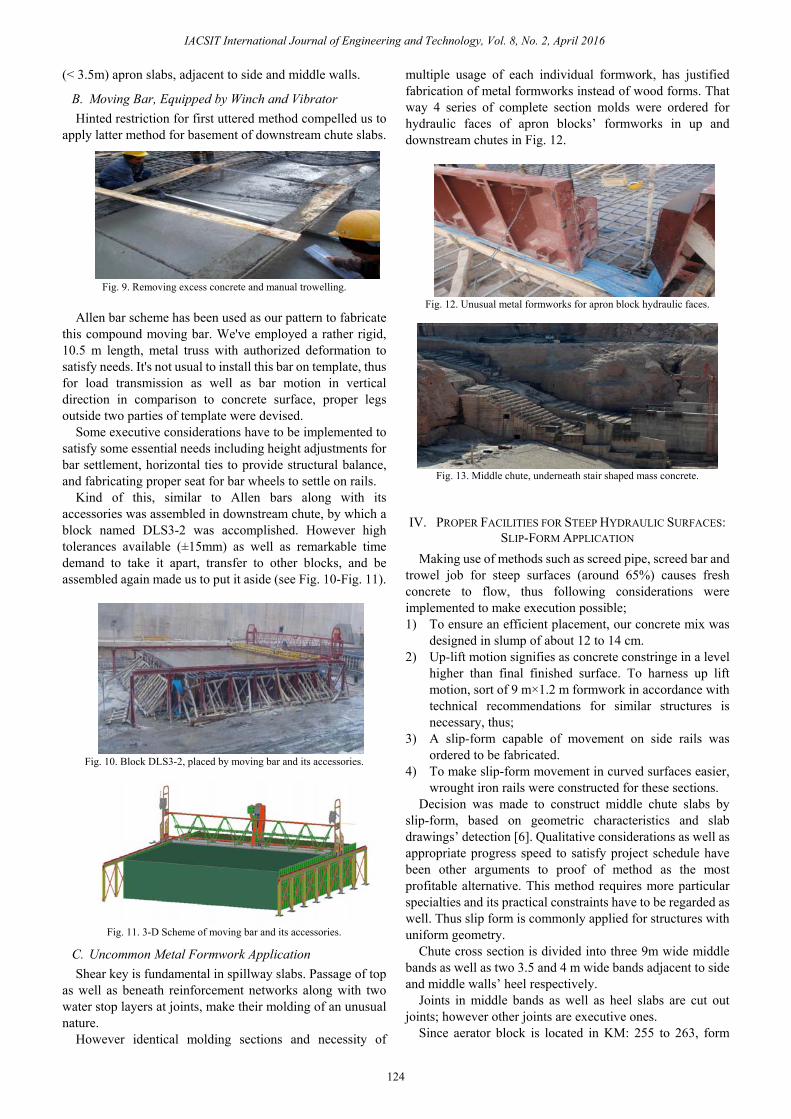
Fig. 13. Middle chute, underneath stair shaped mass concrete.
IV. PROPER FACILITIES FOR STEEP HYDRAULIC SURFACES: SLIP-FORM APPLICATION
Making use of methods such as screed pipe, screed bar and trowel job for steep surfaces (around 65%) causes fresh concrete to flow, thus following considerations were implemented to make execution possible; 1) To ensure an efficient placement, our concrete mix was
designed in slump of about 12 to 14 cm. 2) Up-lift motion signifies as concrete constringe in a level
higher than final finished surface. To harness up lift motion, sort of 9 m×1.2 m formwork in accordance with technical recommendations for similar structures is necessary, thus;
3) A slip-form capable of movement on side rails was ordered to be fabricated.
4) To make slip-form movement in curved surfaces easier, wrought iron rails were constructed for these sections.
Decision was made to construct middle chute slabs by slip-form, based on geometric characteristics and slab drawings’ detection [6]. Qualitative considerations as well as appropriate progress speed to satisfy project schedule have been other arguments to proof of method as the most profitable alternative. This method requires more particular specialties and its practical constraints have to be regarded as well. Thus slip form is commonly applied for structures with uniform geometry.
Chute cross section is divided into three 9m wide middle bands as well as two 3.5 and 4 m wide bands adjacent to side and middle walls’ heel respectively.
Joints in middle bands as well as heel slabs are cut out joints; however other joints are executive ones.
Since aerator block is located in KM: 255 to 263, form
124
IACSIT International Journal of Engineering and Technology, Vol. 8, No. 2, April 2016
movement and concrete placement have been divided into upstream and downstream aerator. Thus 9m bands were placed in several separate steps.
To provide continuous placement, technical items were surveyed and all longitudinal joints along direction of slip-form locomotion were eliminated.
Underneath mass concrete had already been placed in stairs Fig. 13 thus minimum thickness is occurred at each stage edge. Nevertheless 70 cm corresponding thickness available is satisfied minimum technical requirement.
Due to cross section shape, 8 m3 fresh concrete is required per one meter length.
Execution procedure for slip-form usage is as following;
A. Cleaning of Placement Surfaces Stair cleaning as a global prerequisite removes every
detrimental materials of previous surface, including dead concrete, slurries, and etc. To provide more adhesion in between fresh and previously casted concrete, surface was scratched. Debris is removed by water jet and surface is dried by air jet application afterwards.
B. Template Considerations Template preparation is accomplished in two phases. Sine
a longitudinal water stop is planned 30 cm under final surface, formwork is installed from stairs’ surface to beneath water stop level at first. In second phase molds are installed on water stop up to required height, using Iranian planks.
C. Face Reinforcement Face reinforcement according to executive drawings is
performed in two networks. First one is carried out 10 cm beneath final surface in arrangement of about Φ25 @ 200*200 and second network in Φ25 @ 400*200 arrangement, 30cm below upper reinforcement.
Because of complete access available to whole slip-form sections, reinforcement was totally accomplished in advance. Then concrete placement and form movement get started afterwards in Fig. 14.
Whereas common usage of slip form to execute vertical sections is different.
Fig. 14. Middle band, complete face reinforcement.
D. Rail Installation Since section is 9m wide and root of waiting reinforcement
bar for adjacent block is protruded, thus space and level for rail installation should be accurate enough to prevent any conflict with adjacent reinforcements.
That way 50 cm far from side formwork and above reinforcement level, rail cantilevers are installed and fixed.
Two perforated hot rolled beams with U-shaped cross
section were plugged in apron concrete in front of each other in an appropriate distance.
In between U-shaped beams multiple bars were installed by which rail legs are fasten in node shapes.
Rail Legs are fabricated by height-adjustable pipes. Clockwise and anticlockwise screws at middle make rails
capable of height adjustment in 1 mm tolerance. This operation is fulfilled and finalized by an installer, a
welder, a worker, and surveying group during installation procedure in Fig. 15.
Fig. 15. U-Shaped beams and rail preparation.
E. Slip-Form Assembling After rail installation, slip-form has to be assembled. Main body is consisted of two hollow trapezoid shaped
prisms in 4.4m length which are connected to each other using connecting plate in mean.
Formwork contacts to concrete surface via a 68 cm chord. To facilitate form slide on concrete surface, it was
designed 10 cm less wide than section width (9m) at each side.
Thus form is 8.8 m wide and remaining 10 cm at each side has to be finished using bar and hand trowel.
To resist Up-lift pressure a container inside template has been filling in water, that way aside from 3.8 tons of template weight itself, 2.7 tons are added as well.
By taking advantage of plate and resistant bolts, form is seat on carriage and then on rails.
These resistant bolts are responsible for another basic obligation to regulate form height of concrete surface.
It is noticeable that whole process is conducted under inspection of surveying group.
F. Power Supply Required power for template movement could be supplied
of hydraulic, pneumatic, electric, or manual jacks among whom hydraulic jacks are the most economic ones.
Networks of hydraulic jacks are connected to a central reservoir via oil lines and required energy is supplied by electric pump. Each individual jack is calibrated so that, it rises 20 cm in each activation step of electric pump,” Fig. 16”.
Pump pressure should be adequate enough to insure required rise for complete jack network, when it runs. Otherwise template basement turns to an uneven position and formwork will lose its vertical direction. During formwork assembling procedure as well as its movement, presence of an electrician and hydraulic technician is necessary.
G. Concrete Placement Two mixes were designed for face concrete in Table I.
125
IACSIT International Journal of Engineering and Technology, Vol. 8, No. 2, April 2016
Concrete has been transferred to section by pump, mobile pump, or tower crane and bucket for different conditions (see Fig. 17- Fig. 18).
Because of low speed concrete placement mere two truck
mixers were employed. Two layers of upper reinforcement available in structure face, necessitate more accurate handwork concrete vibration [7].
TABLE I: CONCRETE MIX DESIGNS, USED FOR HYDRAULIC SURFACES
Mix Name Con. Class
Slump (cm) W/C Cement
(Kg/m3)(0-5) (Kg/m3)
(5-9.5) (Kg/m3)
(9.5-19) (Kg/m3)
Plasticizer (Kg/m3)
T3 18
19/ 40 12 0.37 380 824 287 805 3.8Reobild
T3 06
19/ 40 14 0.38 400 821 237 766 2.4Pozolith
LD21
Fig. 16. Hydraulic jack (a), electromotor for electric pump (b).
Fig. 17. Concrete transference by mobile pump.
Fig. 18. Concrete transference by tower crane and bucket.
Fig. 19. Concrete placement underneath formwork.
Concrete was placed and vibrated in an appropriate
thickness. When underneath template was filled and initial setting was completed, slip get started (see Fig. 19-Fig. 20).
As a whole, slip speed depends on concrete slump, weather condition, and resulted in setting time. Average speeds of about 40 and 70 cm/hour were recorded in cold and hot seasons respectively.
During 24 hour per day-execution procedure, finished surfaces as well as rails were checked by surveying group
continuously.
H. Concrete Surface Facade When form slips over concrete, provided surfaces were
finished by metal, plank, or plastic trowels. An establishment plank or platform was hanged under
formwork and skillful masons were stand on to make concrete surface smoothly finished using trowel in Fig. 21 and Fig. 22.
Fig. 21. Hanged platform and finishing operation by trowel.
Fig. 22. Slip- Form forehead- connecting winches for workers plank. This platform is connected to formwork and moves by
making use of handwork winches. When finishing is completed, surface was protected of evaporation by moist gunny fabrics and curing process was continued to an assigned satisfactory period.
V. CONCLUSION Since hydraulic surfaces are of utmost importance,
following hints are beneficial and have to be implemented: 1) Formwork, final surface, and water stop position have to
126
IACSIT International Journal of Engineering and Technology, Vol. 8, No. 2, April 2016
be controlled by executive as well as survey inspectors at each section accurately.
2) Water stop has to be accurately located according to shop drawings. It has to be fixed so that its bulb could be seen at mold axis from template inside.
3) Final surfaces, on which prospective traffic is probable, have to be protected by sand coverage.
4) Before every screed or template installation, face control at least in 10 cm of near edge is necessary for adjacent concrete.
5) We have to conform to executive sequences such as preparation, anchor and tool box installation, and locating installation place for CJ molds before apron as well as face reinforcement preparation according to shop drawings.
6) Some inferior template bolts were failed during concrete placement, and then template and hydraulic surfaces of f4 type have been exposed to unfavorable displacement. Thus purchased bolts have to be tested for tensile strength before usage.
7) Edges as well as horizontal and vertical hydraulic faces should be surveyed before formwork installation. Then existent errors have to be calculated and appropriate decisions were made.
8) Accomplished surfaces should be sufficiently protected of every impacts and massive vehicles’ traffic. For instance sand materials are qualified for mutual obligations; impact defense and protecting surface of slurries or fresh concrete.
9) Enough reserved concrete pumps are required to prevent cold joints at each block.
10) Surveys of executed sections have to be compared with that of molds before concrete placement. Then probable errors can be identified and corrected in conjunction with adjacent blocks and next lifts for current block itself.
In order to prevent mold displacement and conform to authorized tolerances for f4 molds, following points should be considered: 1) Bracket foot has to be completely settled in beneath lift
concrete. Mold foot should have minimum overlap of about 10 cm with beneath lift concrete.
2) Horizontal metal props have to be in same direction to connect two panels.
3) Seamless wood beams are so beneficial. 4) Requirements for conic in lifts as well as panels’
conformity to each other according to dimensions of blocks have to be provided.
5) Thorough consistency between template assembling group and executive team is essential.
6) In order to prevent displacement or shear occurrence for bolts in hydraulic formwork, first hydraulic lift has to be accomplished using molds with no consoles.
ACKNOWLEDGMENT Authors wish to thank technical cooperation of Mr. B.
Zafari for designing concrete mixes. Worthwhile helps of Dr. F. Sohrabi and Prof. A. M. Akhoond ali are so appreciated as well.
REFERENCES [1] P. Novak, A. I. B. Moffat, C. Nalluri, and R. Narayanan, Hydraulic
Structures, 4rth ed., Published By Taylor & Francis, 2007. [2] H. Muller, E. Bohner, M. Vogel, V. Kvitsel, and Solichin, “Innovative
solutions for the construction and repair of hydraulic structures,” Procedia Engineering, pp. 22-38, vol. 54, 2013.
[3] L. Tanchev, Dams and Appurtenant Hydraulic Structures, 2nd ed., Published by CRC Press, March 2014.
[4] G. Tandon, “Design of hydraulic structures,” BTCI09007, Assistant Professor at NMIMS, 2014.
[5] K. Bashman and G. Greth, “How to finish flatter concrete floors,” Concrete Contractor, May 18, 2012.
[6] T. Zayed, M. R. Sharifi, S. Baciu, and M. Amer, “Slip-form application to concrete structures” Journal of Construction Engineering and Management, pp. 157-168, 2008.
[7] K. T. Fossa, A. Kreiner, and J. Moksnes, “Slip forming of advanced concrete structures,” Walravan and Stoelhorst(eds) 2008 Taylorand Francis Group, London, pp. 831-836, 2008.
Ali Zabihollah Zadeh was born in Dezful, Iran in 1978 and he earned BSc. degree in irrigation from Shahid Chamran University of Ahwaz, Iran at 2001 as first ranked graduate. He received the MSc. degree in irrigation-hydraulic structures at Shahid Chamran University with major studies on vortex flow hydraulicsat 2004.
He has been engaged as an instructor of Civil Department of Jundi Shapour University and Azad
Universities in the area as well for three years. He cooperated with Karoon Agro-Industerial Company to monitor hydraulic structures available for six months, and he has been hired by Mahab Ghoddss Consulting Engineering Company till now. He acts as the Q.C. inspecting vice president in Upper Gotvand Dam and the head inspector of embankment at one of dam affiliated projects as well.
127
IACSIT International Journal of Engineering and Technology, Vol. 8, No. 2, April 2016