General rights Copyright and moral rights for the publications made accessible in the public portal are retained by the authors and/or other copyright owners and it is a condition of accessing publications that users recognise and abide by the legal requirements associated with these rights. Users may download and print one copy of any publication from the public portal for the purpose of private study or research. You may not further distribute the material or use it for any profit-making activity or commercial gain You may freely distribute the URL identifying the publication in the public portal If you believe that this document breaches copyright please contact us providing details, and we will remove access to the work immediately and investigate your claim. Downloaded from orbit.dtu.dk on: Feb 04, 2020 Exercise in Configurable Products using Creo parametric Christensen, Georg Kronborg Publication date: 2017 Document Version Peer reviewed version Link back to DTU Orbit Citation (APA): Christensen, G. K. (2017). Exercise in Configurable Products using Creo parametric.
Transcript
General rights Copyright and moral rights for the publications made accessible in the public portal are retained by the authors and/or other copyright owners and it is a condition of accessing publications that users recognise and abide by the legal requirements associated with these rights.
Users may download and print one copy of any publication from the public portal for the purpose of private study or research.
You may not further distribute the material or use it for any profit-making activity or commercial gain
You may freely distribute the URL identifying the publication in the public portal If you believe that this document breaches copyright please contact us providing details, and we will remove access to the work immediately and investigate your claim.
Downloaded from orbit.dtu.dk on: Feb 04, 2020
Exercise in Configurable Products using Creo parametric
Christensen, Georg Kronborg
Publication date:2017
Document VersionPeer reviewed version
Link back to DTU Orbit
Citation (APA):Christensen, G. K. (2017). Exercise in Configurable Products using Creo parametric.
Exercise in Configurable Products using Creo parametric By Georg K. Christensen, DTU Mekanik – Konstruktion og Produktudvikling Family tables is a long know method with ProEngineer/Creo parametric to make families of products – like families of bolts and roller bearings. Configurable Products expand these possibilities in two major ways: First it makes configurable assemblies possible where one topologically different component can replace another. Secondly it presents the configurable product in an interactive way which enable the user to experiment with product configurations and different variants in an easy way. In this exercise we will replace a circular axel with a hexagonal axel. (some of this functionality has been available as: configurable assemblies in earlier versions of Creo) An example of a practical application of configurable products is shown below where an outdoor Play/Exercise system is transferred from AutoCAD 2D to a 3D configurable product in Creo 3.0.
TRÆNINGS│PAVILONEN DK at www.TrainingPavilion.com
Ref. 1: Jesper Alkestrup, Kai Paludan-Mȕller og Kristian Ø. Lund: ”Fra tekniske tegninger til fleksible CAD-modeller”, Gruppe 35 fra Videregående CAD, F2015, DTU.
“Trænings pavilion” as modelled in Creo 3.0 (ref 1)
The exercise case is not too practical, but has been selected to introduce the most important features of the configurable product system. In this context the components will be made as simple as possible for fast design – the dimensions of the parts are not critical, but a set of practical dimensions are used.
1) Create a new working directory: Configurable
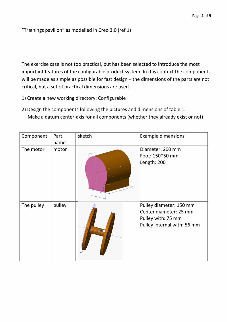
2) Design the components following the pictures and dimensions of table 1. Make a datum center-axis for all components (whether they already exist or not)
Component Part name
sketch Example dimensions
The motor motor
Diameter: 200 mm Foot: 150*50 mm Length: 200
The pulley pulley
Pulley diameter: 150 mm Center diameter: 25 mm Pulley with: 75 mm Pulley internal with: 56 mm
Page 3 of 9
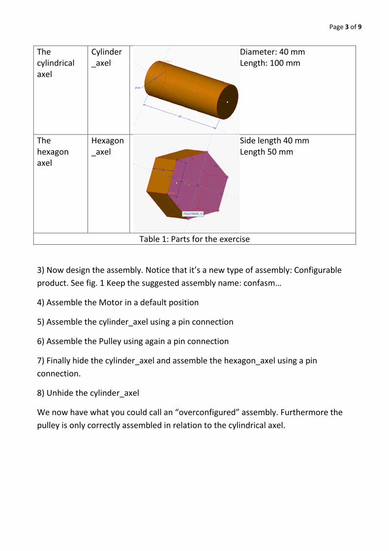
The cylindrical axel
Cylinder_axel
Diameter: 40 mm Length: 100 mm
The hexagon axel
Hexagon_axel
Side length 40 mm Length 50 mm
Table 1: Parts for the exercise
3) Now design the assembly. Notice that it’s a new type of assembly: Configurable product. See fig. 1 Keep the suggested assembly name: confasm…
4) Assemble the Motor in a default position
5) Assemble the cylinder_axel using a pin connection
6) Assemble the Pulley using again a pin connection
7) Finally hide the cylinder_axel and assemble the hexagon_axel using a pin connection.
8) Unhide the cylinder_axel
We now have what you could call an “overconfigured” assembly. Furthermore the pulley is only correctly assembled in relation to the cylindrical axel.
9) Create a new component in the assembly. Make it a subassembly and a configurable module (see fig. 2 and 3) Accept the system name but select “Empty” when asked for a coordinate system (something we wouldn’t normally do) Following this the assembly model tree should now look like fig. 4.
Figure 3 “Empty” creation method Figure 4 Model tree
We will now transfer our axels to the newly create subassembly, Module000x.
10) First Use Transfer to Module: and select the cylindrical axel and transfer it to the new subassem-bly, Module000x. In the reference paring table that pops up – we can see the assembly features used during assembly of the part. Just ignore it for now and press OK. See fig. 5
Page 5 of 9
Figure 5: Transfer of cylinder to configurable module
11) Now select the hexagon_axel and transfer it to the Module000x.
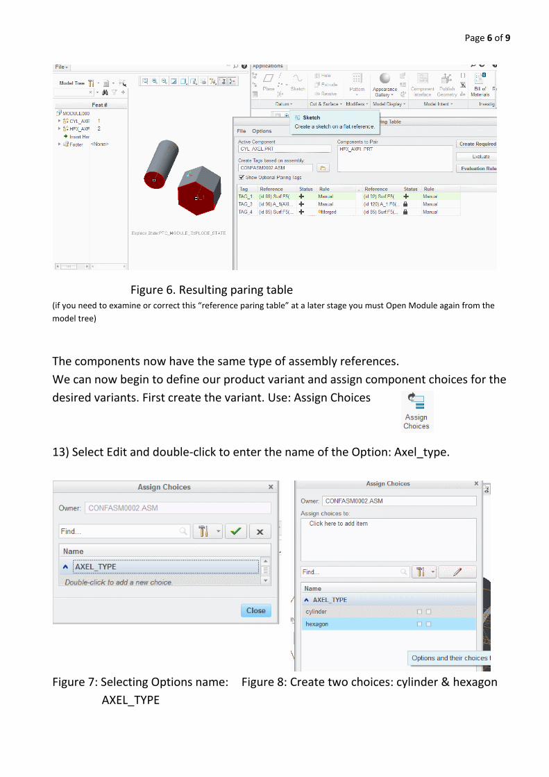
12) Again the reference paring table pops up. This time we see both axel components in the parts window. Select the cylinder as the Active component for paring. Examine the Tag list. The tag list from cylinder will now have to be pared to the tags of the hexagon part. Try manually to select the paring references for the cylinder tags. It might create conflicts of double information. In this case use RMB and merge the conflicting rows. After some editing the paring table should look as shown in fig. 6.
Page 6 of 9
Figure 6. Resulting paring table (if you need to examine or correct this “reference paring table” at a later stage you must Open Module again from the model tree)
The components now have the same type of assembly references. We can now begin to define our product variant and assign component choices for the desired variants. First create the variant. Use: Assign Choices 13) Select Edit and double-click to enter the name of the Option: Axel_type.
14) Create two choices for the axel Option: “cylinder” and “hexagon”. Components will then have to be assigned to the choices names.
15) Click at the “assign choices box at the top and select the cylinder_axel . Proceed and make a mark at the first option name □ following the cylinder option. “Accept it” and re-open the selection. Now insert the hexagon_axel and select the first □ following the hexagon option. Close the assign choices dialog box.
If things have gone correctly we can now invoke the variant builder:
And select the motor assembly variant we want. It should look like fig. 9.
Figure 9 Section of the variant builder
In the options list make a selection of e.g the cylinder □ and notice that the cylinder is selected in the model tree column. Try the hexagon variant, but notice that only one variant is allowed for AXEL_TYPE at a time, so un-click the selection box for cylinder first.
If things seem to work we can open the selected product variant by selecting: “Update Representation” and leave without saving. By this you might get a representation witch is not connected fully. This is because the insertion of a new axel will require
Page 8 of 9
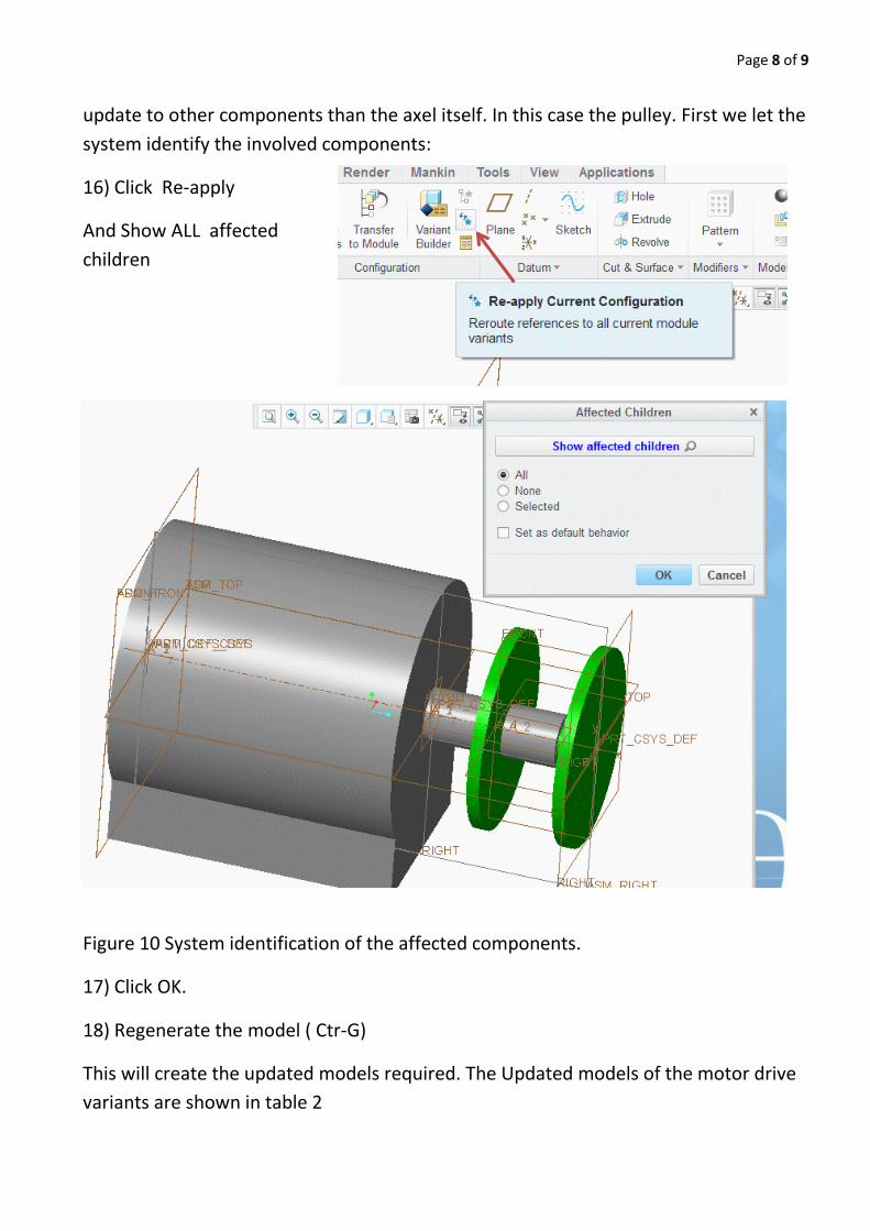
update to other components than the axel itself. In this case the pulley. First we let the system identify the involved components:
16) Click Re-apply
And Show ALL affected children
Figure 10 System identification of the affected components.
17) Click OK.
18) Regenerate the model ( Ctr-G)
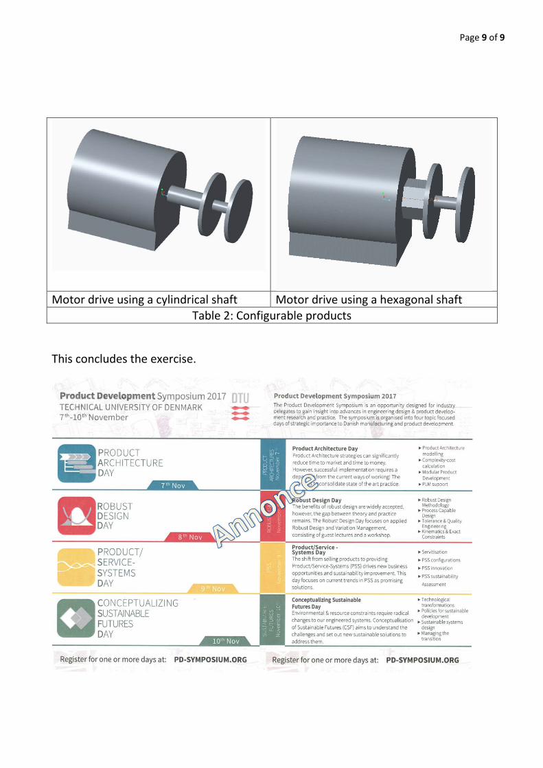
This will create the updated models required. The Updated models of the motor drive variants are shown in table 2
Page 9 of 9
Motor drive using a cylindrical shaft Motor drive using a hexagonal shaft Table 2: Configurable products