In this exercise, you will study how ultrasonic level transmitters operate. You will measure level in a column using an ultrasonic level transmitter and perform on-off control using a relay.
The Discussion of this exercise covers the following points:
Introduction
How does an ultrasonic level sensor work?
Relay control
Characteristics of ultrasonic level sensors
Advantages and limitations
Description of the supplied ultrasonic level transmitter
Introduction
Ultrasonic level sensors use sound waves to detect the level of liquid or solid in different types of containers and environments such as tanks, silos, or even a lake. Ultrasonic sensors are also suitable for flow measurement and level limit detection. They have the advantage of being non-contact sensors, which means they can be used in corrosive environments, and they are not affected by changes in the density, conductivity, and composition of the process fluid or solid. Since they have no moving parts, they also require very low maintenance. Figure 4-23 shows two level measurement applications (solid and liquid), one conveyor belt application, and one flow measurement application for a weir.
Figure 4-23. Typical applications of ultrasonic sensors.
Ultrasonic level sensors are sensitive to temperature changes. For processes where the temperature may vary, a temperature compensation mechanism is required. The quality of the detection is strongly dependent on the quality of the sound wave reflected by the process liquid or solid. This reflected sound wave is called the echo and its intensity is proportional to the square of the distance between the sensor membrane and the surface of the process substance. Thus, the further the sensor is from the surface of the substance, the weaker the echo. The intensity of the echo is also reduced by the natural absorption of the sound wave by air, and by vapor, mist, foam, or dust in the measuring path. The sound waves can be reflected by other apparatuses (such as inlets or other sensors) in the detection path of the sensor. An echo suppression system usually reduces these extra reflections.
How does an ultrasonic level sensor work?
Normal human hearing ranges from about 20 Hz to 20 kHz. In comparison, most ultrasonic level sensors have an operating frequency of over 20 kHz, beyond the upper limit of human hearing. Ultrasonic level sensors use a vibrating diaphragm to produce ultrasonic pulses travelling in the air at the speed of sound. These ultrasound pulses are directed toward the product (liquid or solid) with the level we want to measure. The pulses are reflected at the interface between the air and the medium and travel back to a receiver, which is usually built into the sensor housing. Figure 4-24 shows a standard installation of an ultrasonic level sensor in a vessel.
Figure 4-24. Relevant dimensions for a typical ultrasound set up.
In this figure, BD is the blocking distance. A level cannot be properly evaluated within the blocking distance, because the sensor must first stop emitting a pulse before it can detect its echo, i.e., the reflected signal. If the distance is too short, there is not enough time to emit the whole pulse before the return of the echo which is then not properly detected by the sensor. This is why the level of the product must not be allowed to rise within the blocking distance. F is the span or full distance in which measurements take place, E is the total distance between the sensor membrane and the lowest measureable level of the span, L is the portion of E currently filled with the product, and D is the portion of E which is empty. The emitting angle can be used to calculate the detection radius r for a given height.
The distance between the sensor and the surface of the product is calculated using the velocity of sound in air and by measuring the time between the emission of the pulse and its subsequent reception by the receiver. This method of measuring distances is the time-of-flight measurement method.
(4-13)
where is the distance between the ultrasonic sensor and the surface of the product
is the speed of sound in the air
is the time taken by the ultrasonic pulse to travel to and from the surface of the product
Relay control
Ultrasonic transmitters are often bundled with relays that open and close at discrete levels. These relays can be configured for a given application (e.g., pump control, overflow) as shown in the examples below.
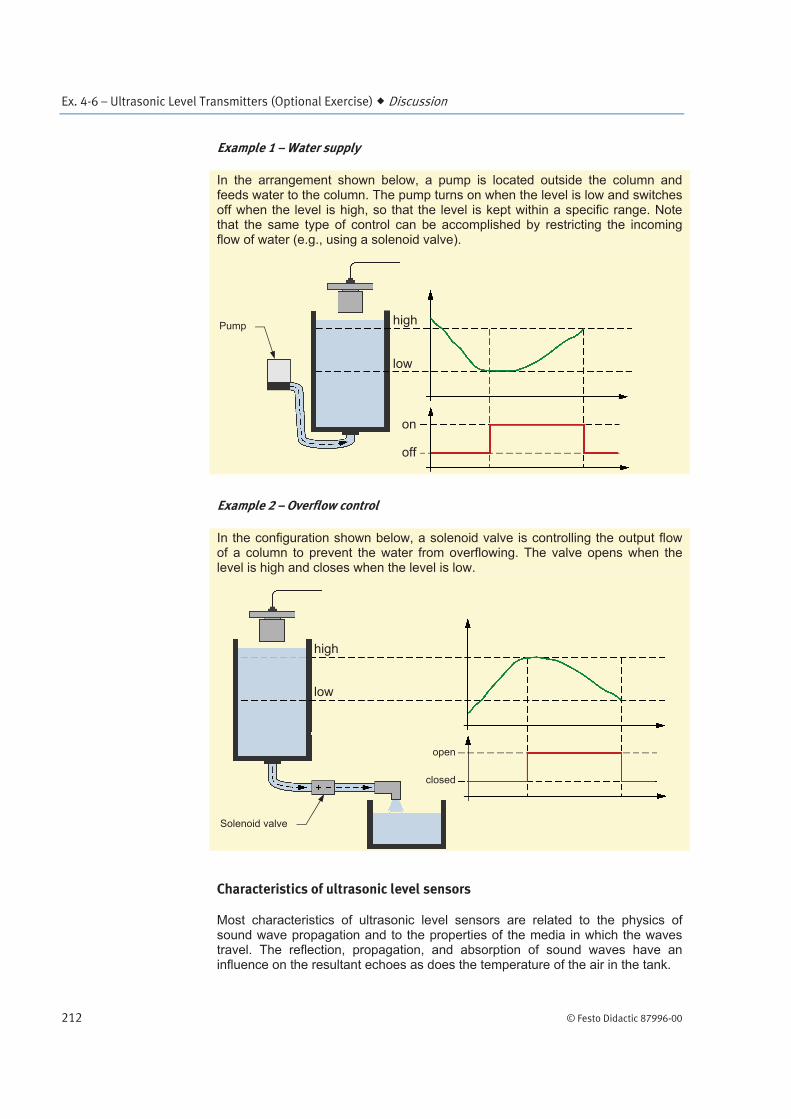
In the arrangement shown below, a pump is located outside the column and feeds water to the column. The pump turns on when the level is low and switches off when the level is high, so that the level is kept within a specific range. Note that the same type of control can be accomplished by restricting the incoming flow of water (e.g., using a solenoid valve).
Example 2 – Overflow control
In the configuration shown below, a solenoid valve is controlling the output flow of a column to prevent the water from overflowing. The valve opens when the level is high and closes when the level is low.
Characteristics of ultrasonic level sensors
Most characteristics of ultrasonic level sensors are related to the physics of sound wave propagation and to the properties of the media in which the waves travel. The reflection, propagation, and absorption of sound waves have an influence on the resultant echoes as does the temperature of the air in the tank.
As specified above, the speed of sound is used to calculate the distance between the sensor and the surface of the product. Therefore, to measure the level correctly, the sensor must use the correct value for the speed of sound.
If air is treated as an ideal gas, the speed of sound is influenced only by the air temperature. When measuring a level using an ultrasonic level sensor, a correction must be made to the time-of-flight to compensate for the change in the speed of sound due to temperature variations. Equation (4-14) gives the relation between the speed of sound in the air and the temperature.
°°
(4-14)
where is the speed of sound (m/s)
° is 331.3 m/s, the speed of sound at 0°C
° is the temperature (°C)
Equation (4-15) is an approximate formula to calculate the speed of sound derived from Equation (4-14) using Taylor series expansion. This equation is
valid for ° much smaller than 273.15°C.
° ° (4-15)
The previous equations can be restated in US customary units as shown below:
°°
(4-16)
where is the speed of sound (ft/s)
° is 1086.9 ft/s, the speed of sound at 32°F
° is the temperature (°F)
This yields the following approximation for °
° (4-17)
Equation (4-15) or Equation (4-17) shows that (for dry air at normal pressure) the speed of sound is approximately proportional to the temperature. As the temperature increases, so will the velocity of the ultrasound pulses. If no temperature compensation is used, the changes in the value of the speed of sound add an error of 1.8% to the measured level for each 10°C augmentation (1% error per 10 °F). This clearly demonstrates the need for a temperature compensation system on ultrasonic level sensors in order to retain adequate precision.
What are the factors influencing the intensity of the echo?
To measure a level, the sensor must detect the echo of the emitted ultrasonic pulse. In order to do so, the echo must have a sufficient intensity to be detected. Many factors influence the intensity of the echo; the most important ones are related to the propagation, absorption, and reflection of sound waves.
Sound waves naturally disperse as they propagate so that their intensity is inversely proportional to the square of the distance traveled. The more distance there is between the ultrasonic sensor and the surface of the product, the weaker the intensity of the echo is.
When the ultrasonic pulse hits the surface of the product, a portion of its energy is absorbed by the product instead of being reflected, thus diminishing the intensity of the returning sound wave. A sharp transition between the air and the medium whose level is to be measured is advisable to obtain reliable measurements. Foam, for example, can cause discrepancies when measuring the level of liquid in a tank with an ultrasonic level sensor.
To measure the level of product, the ultrasonic pulse must return to the sensor. This does not happen if the sensor membrane is not parallel to the surface of the measured product. When ultrasonic pulses are produced by the sensor, they travel in a straight line. If the angle of incidence of the ultrasonic pulse with respect to the surface normal is not 0° (i.e., perpendicular to the surface) the pulse is reflected with an angle and the echo is likely to miss the sensor and escape detection.
Advantages and limitations
Ultrasonic technologies can be used for a large spectrum of applications and are typically very reliable. This explains why devices using ultrasound signals are so widespread in the industry. Some of their main advantages are:
They are non-contact sensors and are suitable for most liquids and bulk
products.
They are reliable and accurate.
However, some limitations should also be considered:
The surface of the product must be still and smooth to ensure the quality
of the reading.
The temperature must remain within operational bounds and has to be
uniform throughout the path of the sound wave to avoid unreliable
results.
Description of the supplied ultrasonic level transmitter
The ultrasonic level transmitter (Model 6545) designed for the Process Control Training System is shown in Figure 4-25. It is composed of an ultrasonic sensor/emitter that can be inserted on top of column and a transmitter that can be connected to a computer for use of the accompanying software, SenixVIEW™.
Technical specifications for the ultrasonic level transmitter are summarized in the table below. For more details, please refer to the documentation provided with the device.
Operating frequency of the sensor
125 kHz
Operating temperature of the sensor
-40 to 70°C (-40 to 158°F)
Blocking distance of the sensor (RangeMIN in SenixVIEW)
6.4 cm (2.5 in)
Optimum range 203 cm (80 in)
Repeatability 0.1%of target distance
Accuracy 0.5% of target distance
Analog resolution 41 000 steps over chosen range
Serial data resolution 0.086 mm (0.003384 in)
The Procedure is divided into the following sections:
Set up and connections
Varying the column level
Measuring the water level
Using the relays
End of the exercise
Set up and connections
General arrangement
1. Get the ultrasonic level transmitter and the column from your storage location. Install the sensor on top of the column as shown in Figure 4-26 and connect the ultrasonic sensor cable to the transmitter.
Figure 4-27. Measuring the water level using an ultrasonic level transmitter.
3. Make sure the reservoir of the pumping unit is filled with about 12 L (3.2 gal) of water. Make sure the baffle plate is properly installed at the bottom of the reservoir.
4. On the pumping unit, adjust valves HV1 to HV3 as follows:
Open HV1 completely.
Close HV2 completely.
Set HV3 for directing the full reservoir flow to the pump inlet.
Commissioning the ultrasonic level transmitter
5. Connect the communication cable between the transmitter and your computer. Use the provided serial-to-USB adapter, if necessary.
6. Power up the transmitter.
7. If the software is not already installed on your computer, insert the SenixVIEW™ software disk and run setup.exe. Follow the on-screen instructions to install the software.
11. Select a distance unit (Edit User Preferences Distance Units) and click OK.
12. Click on the Workspace icon to return to the editable version of the sensor parameters (Figure 4-30).
Figure 4-30. Default workspace.
13. Editable parameters are displayed in blue. High Value and Low Value are the transmitter output signal. By default, they are set to 20 mA (or 10 V dc) and 4 mA (or 0 V dc) by default.
LVProSim
You can use LVProSim to monitor the 4-20 mA output of the transmitter. To do so, connect the computer running LVProSim to the transmitter via the I/O interface. Refer to Appendix B for details on how to make the connections and how to use LVProSim.
a It is not recommended to set Range MIN smaller than the default value and Range MAX larger than the default value as the sensor may yield incorrect distance values outside these boundaries.
Varying the column level
14. Turn on the pumping unit.
Not equal symbol indicates that workspace and sensor parameters are different
Black border indicates whichset of parameters is displayed
15. Set the pump speed to a low value. Stop the pump when the level of waterslightly exceeds the bottom of the column ruler. Close HV1 when water isexactly in front of the 0 cm (0 in) mark.
16. In SenixVIEW, go to the Sensor view. What position is measured by thesensor?
17. Restart the pump and add water until you exceed the 55 cm (or 22 in) rulermark. Stop the pump and change HV3 position to prevent water to return tothe reservoir through the pump. How is the measurement value obtained inSenixVIEW? Explain what happens.
18. Open and close HVI until water level is exactly equal to 50 cm (or 20 in) onthe ruler. What position is measured by the sensor?
19. Return to the Workspace view. Enter the value of step 16 as the Low ValueEndpoint and the value of step 1 as the High Value Endpoint.
20. Copy the workspace to the sensor (Sensor Move Workplace to Sensor).
Measuring the water level
21. Vary the water level in the column by 5 cm (2 in) steps using HV 1 andrecord your results in Table 4-6. The table Analog Output column requiresthat you either:
read the actual output on the transmitter.
use the simulated current or voltage reading given by SenixVIEW (Large
23. From the data recorded in Table 4-6, plot the relationship between the ruler and SenixVIEW readings.
24. How would you characterize this relationship?
25. From the data recorded in Table 4-6, plot the relationship between the ruler and analog output readings.
26. How would you characterize this relationship?
Using the relays
27. On the Workspace view, click the Wiring icon. Set the transmitter relays (Switch #1 and Switch #2) to Switch (Sourcing-PNP) as shown in Figure 4-31 The relays are now configured to be open in the Off state and closed in the On state. Click OK to return to the Workspace view.
28. Get the Solenoid Valve from your storage location. Make the connections shown in Figure 4-32 to prepare for a simple on-off control of the water level using Switch 1. Connect one switch terminal to the solenoid valve and the other terminal to a 24 V dc supply.
Figure 4-32. Simple On-Off control scheme using the transmitter.
29. On the Workspace view, click the Switches icon. Set Switch #1 Polarity to ON-Farther as shown in Figure 4-33. That way, the switch is activated (open state) when the level is low and deactivated (closed state) when the level is high. Click OK.
30. Back on the Workspace view, set Switch 1 Setpoint to an intermediate value (e.g., 34.5 cm or 13.40 in).
31. Copy the workspace to the sensor (Sensor Move Workplace to Sensor). Switch 1 is now configured to open the solenoid valve when the level is below the set point and permits the water to flow into the column.