Exergetic analysis of a continuous Bi-axially Oriented Polypropylene (BOPP) film unit in a plastic processing plant
M. Tolga Balta and Arif Hepbasli* Faculty of Engineering, Department of Mechanical Engineering, Ege University, TR-35100 Bornova, Izmir, Turkey E-mail: [email protected] E-mail: [email protected] *Corresponding author
Ebru Hancioglu Geothermal Energy Research and Application Center, Izmir Institute of Technology, TR-35437 Urla, Izmir, Turkey E-mail: [email protected]
S. Cihangir Ozcanli Department of Mechanical Engineering, Izmir Institute of Technology, TR-35430 Urla, Izmir, Turkey E-mail: [email protected]
Ertan Yilmazer, Ibrahim Yurdakul and Ozgur Disbudak Energy Department, Polinas Plastics Inc., Organized Industrial Region, 45030 Manisa, Turkey E-mail: [email protected] E-mail: [email protected] E-mail: [email protected]
Abstract: This paper deals with an exergy analysis of the stretching process of bi-axially oriented polypropylene films using a hot oil coiler along with stretching and crystallising unit. Exergy destructions and efficiencies in each of the system components are calculated, while the exergy loss and flow diagram (the so-called Grassmann diagram) is presented for the transverse direction (TD) unit. The so-called functional (on the product or benefit/fuel basis) and universal (on the output/input basis) exergy efficiency values of the TD unit are calculated to be 26.40% and 28.46% at a recommended exhaust air relative humidity of 0.0098 kg water/kg air, respectively.
Exergetic analysis of a continuous Bi-axially Oriented Polypropylene 441
Reference to this paper should be made as follows: Balta, M.T., Hepbasli, A., Hancioglu, E., Ozcanli, S.C., Yilmazer, E., Yurdakul, I. and Disbudak, O. (2009) ‘Exergetic analysis of a continuous Bi-axially Oriented Polypropylene (BOPP) film unit in a plastic processing plant’, Int. J. Exergy, Vol. 6, No. 3, pp.440–456.
Biographical notes: Mustafa Tolga Balta is a research assistant in Mechanical Engineering at Ege University, Izmir, Turkey. He received his BSc and MSc Degrees in Mechanical Engineering from Nigde University in 2001 and 2005, respectively. Some of his research areas include energy, exergy and exergoeconomic analyses of thermal systems and ground-source heat pumps.
Arif Hepbasli is a full Professor of Mechanical Engineering at Ege University, Izmir, Turkey. Before joining the university in 1996, he worked for ten years in various Turkish energy companies. His research has been involved with energy, exergy and exergoeconomic analyses of thermal systems, energy efficiency and management, ground-source heat pumps, and utilisation and potential of renewable energy sources. He worked as a Visiting Professor during 2004–2005 at the University of Ontario Institute of Technology in Canada. He is a member in the International Advisory Board of five prestigious international journals.
Ebru Hancioglu is a specialist in Geothermal Energy Research and Application Center at Izmir Institute of Technology in Turkey. She received her BSc Degree in Chemical Engineering at Yildiz Technical University, Istanbul and her MSc and PhD Degrees from the Solar Energy Institute, Ege University, Izmir, Turkey.
S. Cihangir Ozcanli is the Founder of Kaltek Engineering. He received his BSc Degree in Mechanical Engineering from METU, Ankara, Turkey, his Post Graduate Diploma from Von Karman Institute for Fluid Dynamics, Brussels, Belgium and his PhD Degree from the School of Mechanical Engineering, Cranfield Institute of Technology, England.
Ertan Yilmazer received his BSc in Electrical Engineering from Istanbul University in 1994. He has been working for nine years as a Project, Maintenance and Utilities Manager at Polinas Plastics Inc., Manisa, Turkey.
Ibrahim Yurdakul received his BSc in Mechanical Engineering and MSc Degree in Industrial Engineering from Yildiz Technical University in 1998 and 2001, respectively. He has been working for three years as a Senior Project Engineer at Polinas Plastics Inc., Manisa, Turkey.
Ozgur Disbudak received his BSc in Electrical Engineering from Istanbul Technical University in 1998. He has been working for six years as a Senior Project Engineer at Polinas Plastics Inc., Manisa, Turkey.
442 M.T. Balta et al.
1 Introduction
Polypropylene films have been increasingly used in packaging and other applications due to their superior moisture barrier properties, clarity, gloss, dimensional stability, strength, aroma resistance and processability. Because of their unique properties, annual growth rates of over 6% are expected in the coming years (Chemical Market Resources CMR, 2002). Polypropylene (PP) is commonly used to make biaxially oriented films, of which worldwide production exceeded three million tons in 2001 and is predicted to nearly double by 2010 (Chemical Market Resources CMR, 2002). Solid-state stretching produces Bi-axially Oriented Polypropylene (BOPP) films that are stronger, stiffer, clearer, and less permeable than typical unoriented films (Tsunashima et al., 1999). These oriented films are found in applications such as snack food packaging and bottle labels. Opportunities also exist in numerous specialty markets as well, such as in synthetic paper and banknotes (Coventry, 1999; Breil, 2002).
BOPP film, produced either by tubular or tenter process, has been widely used in packaging. The BOPP film studied in this work was produced by the tenter process, as follows:
The PP sheet is extruded through a flat die and cooled under controlled conditions in a subsequent stage. This film is reheated to be treated for orientation. First, the film passes over a system of rolls running at different speeds so that orientation in the ‘Machine Direction (MD)’ takes place (Vassiliadi and Tarantili, 2007). After the MD the sheet enters the oven, commonly called the ‘Transverse Direction (TD)’ section.
One of the thermal systems is a TD unit of BOPP film production, which is a combination of a hot-oil coil unit and an oven; it has been used in many oven applications.
In the TD the film is heated in the preheat section by high velocity hot air blowing on both sides of the film. The preheat section prepares the film for the stretching section where the tracks are pre-set to the desired stretch profile. Following the transverse stretching the film is annealed cooled and exits the oven.
In the BOPP film production, TD unit is the most energy-intensive operation and easily accounts for up to 65.61% of BOPP film production energy utilisation. Thus, for reducing energy consumption per unit of stretching the product, it is necessary to examine different methodologies to improve the energy efficiency of the TD equipment.
Exergy analysis is a very useful tool, which can be successfully used in the design of an energy system and provides the useful information to choose the appropriate component design and operation procedure. This information is much more effective in determining the plant and operation cost, energy conservation, fuel versatility and pollution. In recent years, exergy analysis has been widely used for the performance evaluation of thermal systems. By using exergy analysis method, the magnitudes and locations of exergy destructions (irreversibilities) in the whole system are identified, while potential for energy efficiency improvements is introduced (Hancioglu and Hepbasli, 2007).
In the literature, numerous studies on energy and exergy analysis, and optimisation of thermal systems have recently been carried out by many researchers. Among these, industrial dryers have been exergetically assessed by some investigators (i.e., Dincer and Hussain, 2002; Dincer and Sahin 2004; Cay et al., 2007). However, no studies on exergetic evaluation of BOPP films oven (stretching) systems have appeared in the open literature to the best of the authors’ knowledge. This was the motivation behind the
Exergetic analysis of a continuous Bi-axially Oriented Polypropylene 443
present study, which exergetically assesses a TD unit of the continuous production line in a plastic processing plant based on the actual operational data. In this context, a unit consisting of a hot oil coiler and waste heat system is analysed and investigated for performance assessment purposes. It is expected that this study would be of great importance, being the very first and original reference document for the exergetic evaluation of TD processes.
2 System description
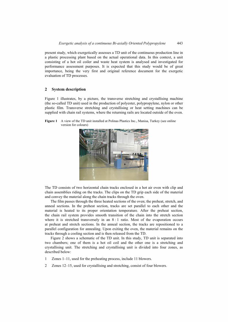
Figure 1 illustrates, by a picture, the transverse stretching and crystallising machine (the so-called TD unit) used in the production of polyester, polypropylene, nylon or other plastic film. Transverse stretching and crystallising or heat setting machines can be supplied with chain rail systems, where the returning rails are located outside of the oven.
Figure 1 A view of the TD unit installed at Polinas Plastics Inc., Manisa, Turkey (see online version for colours)
The TD consists of two horizontal chain tracks enclosed in a hot air oven with clip and chain assemblies riding on the tracks. The clips on the TD grip each side of the material and convey the material along the chain tracks through the oven.
The film passes through the three heated sections of the oven; the preheat, stretch, and anneal sections. In the preheat section, tracks are set parallel to each other and the material is heated to its proper orientation temperature. After the preheat section, the chain rail system provides smooth transition of the chain into the stretch section where it is stretched transversely in an 8 : 1 ratio. Most of the evaporation occurs at preheat and stretch sections. In the anneal section, the tracks are repositioned to a parallel configuration for annealing. Upon exiting the oven, the material remains on the tracks through a cooling section and is then released from the TD.
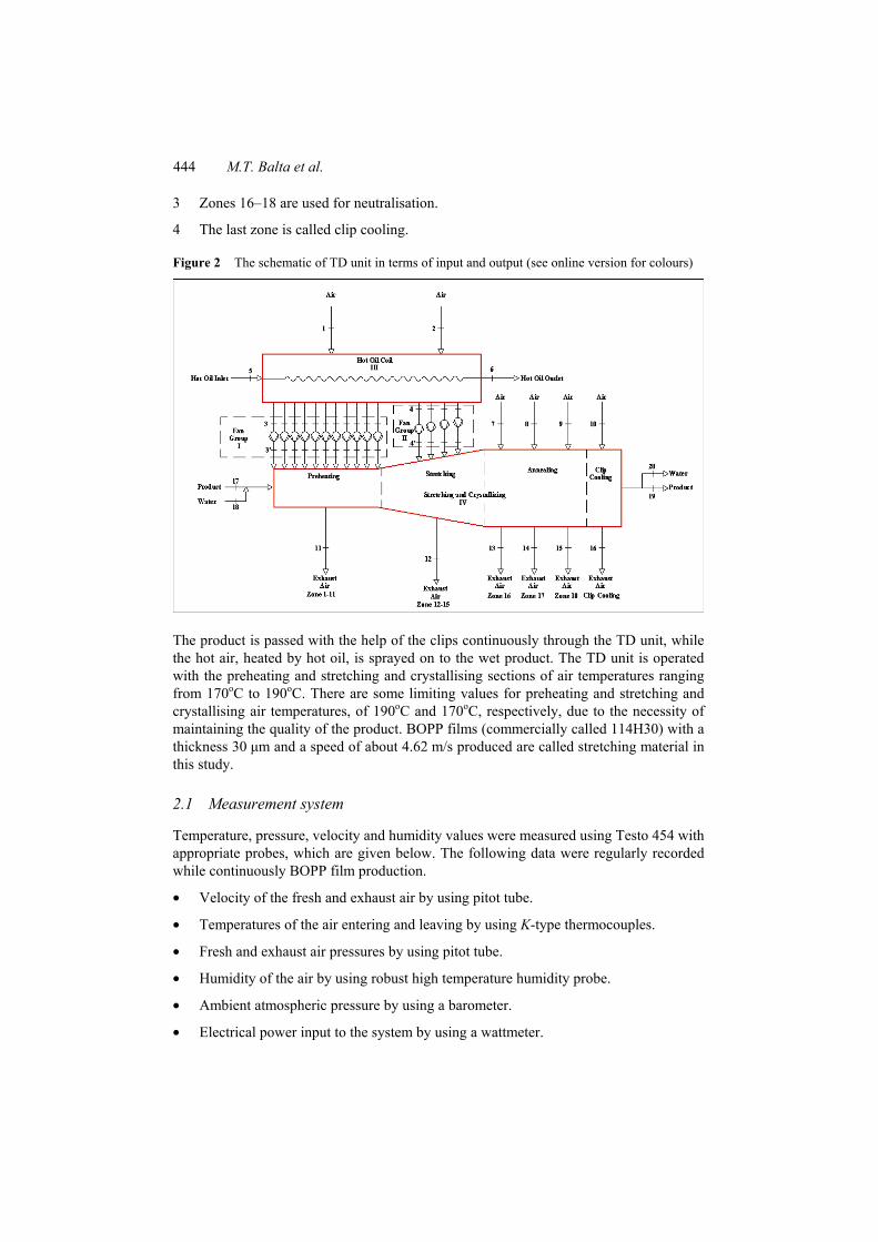
Figure 2 shows a schematic of the TD unit. In this study, TD unit is separated into two chambers; one of them is a hot oil coil and the other one is a stretching and crystallising unit. The stretching and crystallising unit is divided into four zones, as described below:
1 Zones 1–11, used for the preheating process, include 11 blowers.
2 Zones 12–15, used for crystallising and stretching, consist of four blowers.
444 M.T. Balta et al.
3 Zones 16–18 are used for neutralisation.
4 The last zone is called clip cooling.
Figure 2 The schematic of TD unit in terms of input and output (see online version for colours)
The product is passed with the help of the clips continuously through the TD unit, while the hot air, heated by hot oil, is sprayed on to the wet product. The TD unit is operated with the preheating and stretching and crystallising sections of air temperatures ranging from 170oC to 190oC. There are some limiting values for preheating and stretching and crystallising air temperatures, of 190oC and 170oC, respectively, due to the necessity of maintaining the quality of the product. BOPP films (commercially called 114H30) with a thickness 30 µm and a speed of about 4.62 m/s produced are called stretching material in this study.
2.1 Measurement system
Temperature, pressure, velocity and humidity values were measured using Testo 454 with appropriate probes, which are given below. The following data were regularly recorded while continuously BOPP film production.
• Velocity of the fresh and exhaust air by using pitot tube.
• Temperatures of the air entering and leaving by using K-type thermocouples.
• Fresh and exhaust air pressures by using pitot tube.
• Humidity of the air by using robust high temperature humidity probe.
• Ambient atmospheric pressure by using a barometer.
• Electrical power input to the system by using a wattmeter.
Exergetic analysis of a continuous Bi-axially Oriented Polypropylene 445
2.2 Uncertainty analysis
Uncertainty analysis is needed to prove the accuracy of the experiments. An uncertainty analysis was performed using the method described by Holman (2001). In the present study, the temperatures, velocities, pressure drops and electrical power were measured with appropriate instruments, as explained earlier. The total uncertainties of the measurements are estimated to be ±0.4% for the temperatures, ±2% for the humidity, ±0.5% for pressures, ±1.5% for power inputs to the TD unit. Uncertainty in reading values of the table is assumed to be ±0.20%. The total uncertainties associated with the specific exergy rates of the exhaust air and exergy efficiency of TD are found to be ±2.10% and ±2.97%, respectively.
3 Analysis
The following assumptions are considered for the analysis.
• All processes are steady-state and steady flow with negligible potential energy effects.
• Heat transfer to the system and work transfer from the system are positive.
• Specific chemical exergy of the hot oil is neglected since there is no chemical reaction during the circle.
• All the data collected after the continuous stretching processes are obtained under the steady-state operating conditions.
• Data are obtained directly from the screens and measured on the system.
The specific flow exergy is evaluated as (Cengel and Boles, 2001)
0 0 0( ) ( )ex h h T s s= − − − (1)
where h is the specific enthalpy, s is the specific entropy, and the subscript zero indicates properties at the reference (dead) state.
The specific exergy for the moist products results in
0 0 0 0 0[ ( , ) ( , )] [ ( , ) ( , )].p p p p pex h T P h T P T s T P s T P= − − − (1a)
The specific exergy of air is calculated from the following relation (Wepfer et al., 1979).
moist air , , 0 0 00 0
00
0
( ) ln (1 ) ln
1(1 ) ln ln1
p a p w a
a
T Pex C C T T T R TT P
R T
ω ω
ω ωω ωω ω
= + − − + +
+
+ + + + (3)
446 M.T. Balta et al.
where
1.608ω ω= (3a)
0 01.608ω ω= (3b)
/ .w am mω = (3c)
Kinetic exergy is calculated as follows: 21/ 2 .kex V= (4)
The exergy rate is determined by
.Ex m ex= ⋅ (5)
The Relative Irreversibility (RI) is evaluated as (van Gool, 1997),
dest.
totdest.tot
RI .i iEx İİEx
= = (6)
The functional exergetic efficiency of the stretching and crystallising unit depends on the ratio of exergy use in the stretching of the product to exergy of the stretching and crystallising air supplied to the system, which is a modified form of Dincer and Sahin’s (2004) model and is calculated from:
, funcExergy investment in the evaporation of moisture in the product
Exergy of stretching and crystallising air suppliedSCε =
, , , 18, func
3' 4 '
( )( )
w ev w ea wSC
a
m ex exm ex ex
ε−
=+
(7)
with
, 20 18w evm m m= − (7a)
0, , 0 0 , 0 0 0
0
( )[ ( , ) ( )] [ ( , ) ( )] ln g
w ea ea v ea g ea v ea g vv
P Tex h T P h T T s T P s T T R
x P
= − − − +
(7b)
, ( ) .v ea v ea eaP x P= (7c)
The exergetic efficiency of the TD unit is calculated using two different definitions, which are called universal and functional exergy efficiencies.
The universal exergetic efficiency relation used is given below, as applied to drying systems by some investigators (i.e., Midilli and Kucuk, 2003; Akpinar et al., 2006). The universal exergetic efficiency can be defined as the ratio of the product exergy to exergy inflow as follows:
, univ 1 .LTD
in
ExEx
ε = − (8)
Exergetic analysis of a continuous Bi-axially Oriented Polypropylene 447
The second one may be defined on the product/fuel basis, as given in equation (8a).
out, func
in
.TDExEx
ε = (8a)
The exergy efficiency of the fans is found using:
out infan
fan
( ) .kEx Ex ExW
ε − += (9)
The enthalpy equation of the fan outlet in equation (10) was derived (Midilli and Kucuk, 2003)
, out
2
, out , in1 .
2 1000f
f f fa
Vh W h
m
= + + ×
(10)
The mechanical–electrical losses are obtained as follows (Kotas, 1995):
dest, mech, elec , elec , elec , mech(1 )f f fEx W η η= − (11)
where, , infh characterises the enthalpy of air at the inlet of the fan, , outfh the enthalpy at the outlet of the fan, , outfV the stretching air velocity at the outlet of the fan, fW fan energy and am mass flow of air.
Van Gool (1997) has also proposed that maximum improvement in the exergy efficiency for a process or system is obviously achieved when the exergy loss or irreversibility in out( )Ex Ex− is minimised. Consequently, he suggested that it is useful to employ the concept of an exergetic ‘improvement potential’ when analysing different processes or sectors of the economy. This improvement potential in the rate form, denoted as IP , is given by Hammond and Stapleton (2001).
in out(1 )( ).IP Ex Exε= − − (12)
The Specific Moisture Extraction Rate (SMER), defined as the ratio of the moisture removed, in kg, to the energy input, in kWh, is obtained from (Hawlader and Jahangeer, 2006).
Moisture removed in kgSMER= .Energy input in kWh
(13)
The Specific Moisture Exergetic Rate (SMExR) is defined as the ratio of the moisture removed in kg to the exergy input in kWh and indicates the effectiveness of the exergy input in the process; it is calculated using the following relation proposed by Hancioglu and Hepbasli (2007).
Moisture removed in kgSMExR= .Exergy input in kWh
(14)
448 M.T. Balta et al.
4 Results and discussion
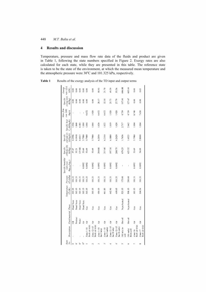
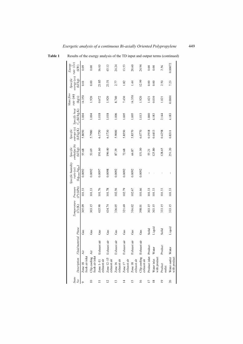
Temperature, pressure and mass flow rate data of the fluids and product are given in Table 1, following the state numbers specified in Figure 2. Exergy rates are also calculated for each state, while they are presented in this table. The reference state is taken to be the state of the environment, at which the measured mean temperature and the atmospheric pressure were 30oC and 101.325 kPa, respectively.
Table 1 Results of the exergy analysis of the TD input and output terms
Exergetic analysis of a continuous Bi-axially Oriented Polypropylene 449
Table 1 Results of the exergy analysis of the TD input and output terms (continued)
450 M.T. Balta et al.
Table 2 represents exergy destruction and Relative Irreversibility (RI) data for the overall system. The functional and universal exergy efficiency values for the overall system are calculated to be 26.40% and 28.46%, respectively, at an exhaust air relative humidity ratio of 0.0098 kgwater/kgair. The total uncertainties associated with specific exergy rates of the exhaust air and exergy efficiency of TD are found to be ±2.10% and ±2.97%, respectively.
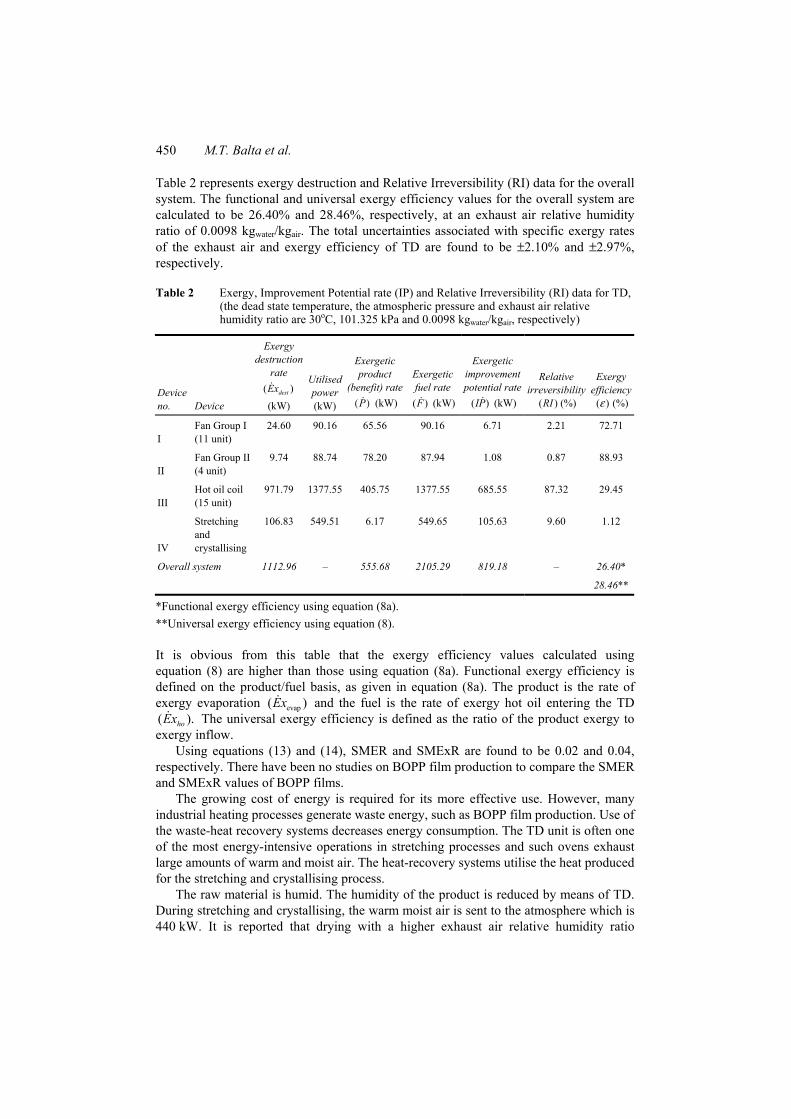
Table 2 Exergy, Improvement Potential rate (IP) and Relative Irreversibility (RI) data for TD, (the dead state temperature, the atmospheric pressure and exhaust air relative humidity ratio are 30oC, 101.325 kPa and 0.0098 kgwater/kgair, respectively)
Device no. Device
Exergy destruction
rate ( )destEx (kW)
Utilised power (kW)
Exergetic product
(benefit) rate P( ) (kW)
Exergetic fuel rate ( )F (kW)
Exergetic improvement potential rate
( )IP (kW)
Relative irreversibility
( )RI (%)
Exergy efficiency
( )ε (%)
I Fan Group I (11 unit)
24.60 90.16 65.56 90.16 6.71 2.21 72.71
II Fan Group II (4 unit)
9.74 88.74 78.20 87.94 1.08 0.87 88.93
III Hot oil coil (15 unit)
971.79 1377.55 405.75 1377.55 685.55 87.32 29.45
IV
Stretching and crystallising
106.83 549.51 6.17 549.65 105.63 9.60 1.12
Overall system 1112.96 – 555.68 2105.29 819.18 – 26.40*
28.46**
*Functional exergy efficiency using equation (8a). **Universal exergy efficiency using equation (8).
It is obvious from this table that the exergy efficiency values calculated using equation (8) are higher than those using equation (8a). Functional exergy efficiency is defined on the product/fuel basis, as given in equation (8a). The product is the rate of exergy evaporation evap( )Ex and the fuel is the rate of exergy hot oil entering the TD ( ).hoEx The universal exergy efficiency is defined as the ratio of the product exergy to exergy inflow.
Using equations (13) and (14), SMER and SMExR are found to be 0.02 and 0.04, respectively. There have been no studies on BOPP film production to compare the SMER and SMExR values of BOPP films.
The growing cost of energy is required for its more effective use. However, many industrial heating processes generate waste energy, such as BOPP film production. Use of the waste-heat recovery systems decreases energy consumption. The TD unit is often one of the most energy-intensive operations in stretching processes and such ovens exhaust large amounts of warm and moist air. The heat-recovery systems utilise the heat produced for the stretching and crystallising process.
The raw material is humid. The humidity of the product is reduced by means of TD. During stretching and crystallising, the warm moist air is sent to the atmosphere which is 440 kW. It is reported that drying with a higher exhaust air relative humidity ratio
Exergetic analysis of a continuous Bi-axially Oriented Polypropylene 451
entertains the risk of condensation of the water vapour because of the wet temperature of the product (Tarakcioglu, 1984).
The processed waste-air is humid and generally polluted with PP vapour and chemical materials, and polluted air cannot be used again in the process directly. Although, with certain heat recovery systems, where PP vapour and chemical materials are purified; the waste heat should then be reused by the system. Fresh, dry and hot air should continuously be recirculated in the TD unit. The heat-recovery system during stretching and crystallising should be taken into consideration for achieving energy savings.
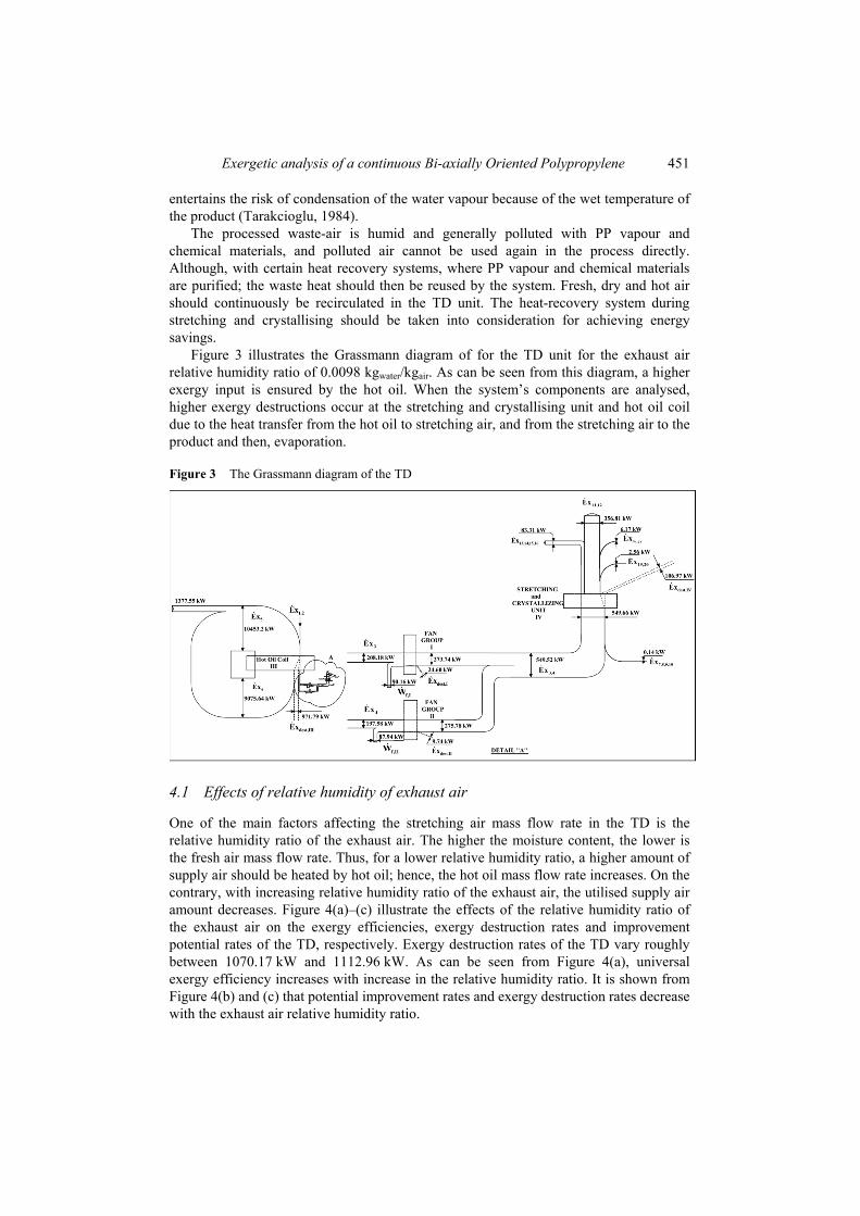
Figure 3 illustrates the Grassmann diagram of for the TD unit for the exhaust air relative humidity ratio of 0.0098 kgwater/kgair. As can be seen from this diagram, a higher exergy input is ensured by the hot oil. When the system’s components are analysed, higher exergy destructions occur at the stretching and crystallising unit and hot oil coil due to the heat transfer from the hot oil to stretching air, and from the stretching air to the product and then, evaporation.
Figure 3 The Grassmann diagram of the TD
4.1 Effects of relative humidity of exhaust air
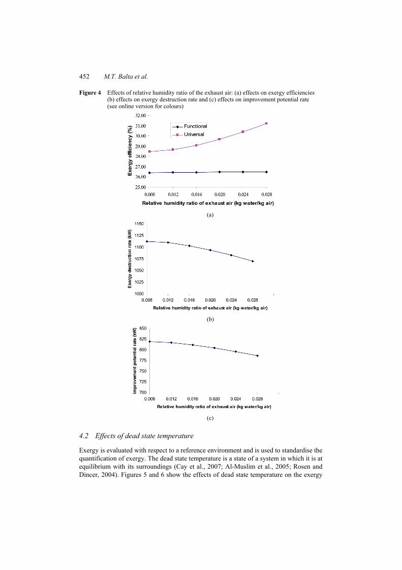
One of the main factors affecting the stretching air mass flow rate in the TD is the relative humidity ratio of the exhaust air. The higher the moisture content, the lower is the fresh air mass flow rate. Thus, for a lower relative humidity ratio, a higher amount of supply air should be heated by hot oil; hence, the hot oil mass flow rate increases. On the contrary, with increasing relative humidity ratio of the exhaust air, the utilised supply air amount decreases. Figure 4(a)–(c) illustrate the effects of the relative humidity ratio of the exhaust air on the exergy efficiencies, exergy destruction rates and improvement potential rates of the TD, respectively. Exergy destruction rates of the TD vary roughly between 1070.17 kW and 1112.96 kW. As can be seen from Figure 4(a), universal exergy efficiency increases with increase in the relative humidity ratio. It is shown from Figure 4(b) and (c) that potential improvement rates and exergy destruction rates decrease with the exhaust air relative humidity ratio.
452 M.T. Balta et al.
Figure 4 Effects of relative humidity ratio of the exhaust air: (a) effects on exergy efficiencies (b) effects on exergy destruction rate and (c) effects on improvement potential rate (see online version for colours)
(a)
(b)
(c)
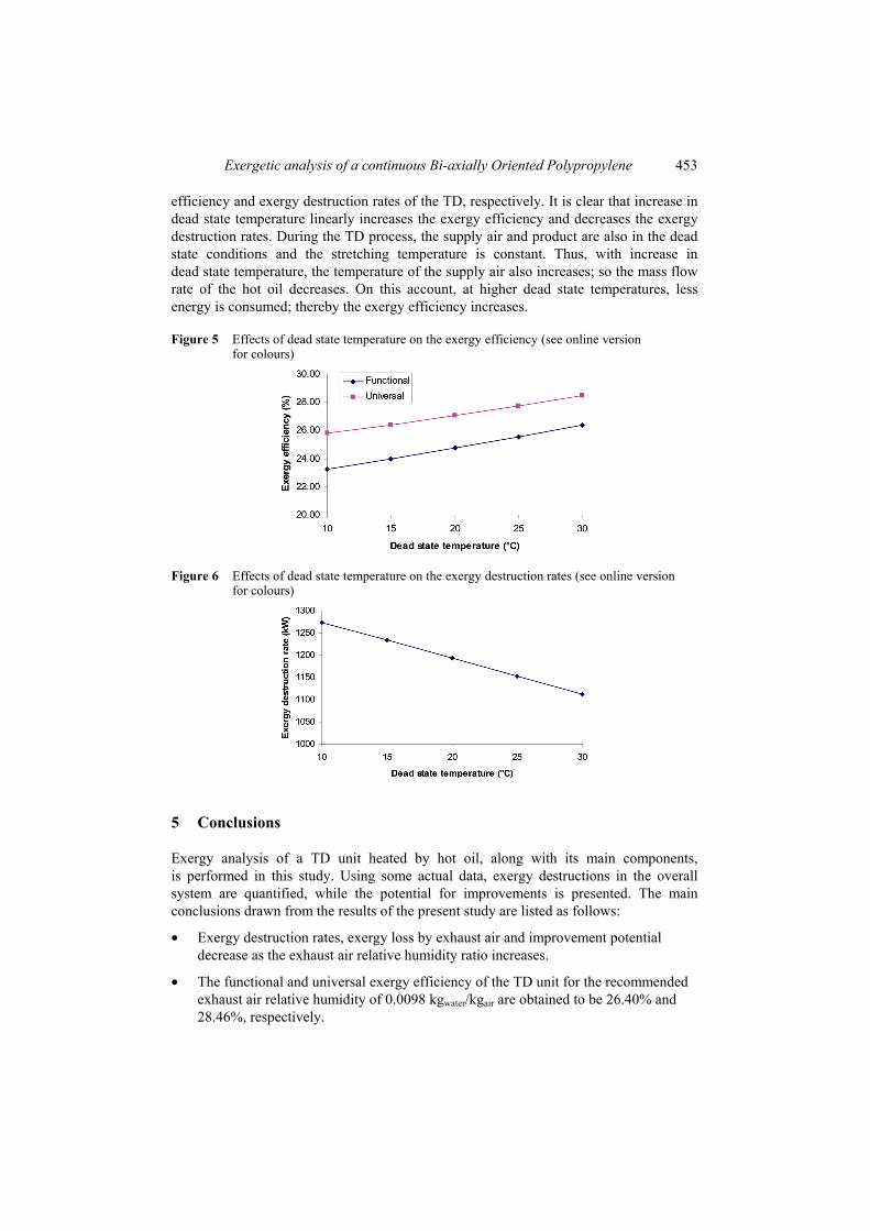
4.2 Effects of dead state temperature
Exergy is evaluated with respect to a reference environment and is used to standardise the quantification of exergy. The dead state temperature is a state of a system in which it is at equilibrium with its surroundings (Cay et al., 2007; Al-Muslim et al., 2005; Rosen and Dincer, 2004). Figures 5 and 6 show the effects of dead state temperature on the exergy
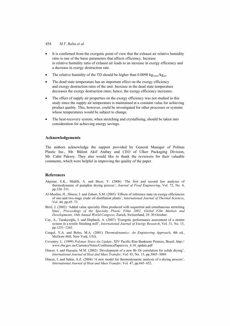
Exergetic analysis of a continuous Bi-axially Oriented Polypropylene 453
efficiency and exergy destruction rates of the TD, respectively. It is clear that increase in dead state temperature linearly increases the exergy efficiency and decreases the exergy destruction rates. During the TD process, the supply air and product are also in the dead state conditions and the stretching temperature is constant. Thus, with increase in dead state temperature, the temperature of the supply air also increases; so the mass flow rate of the hot oil decreases. On this account, at higher dead state temperatures, less energy is consumed; thereby the exergy efficiency increases.
Figure 5 Effects of dead state temperature on the exergy efficiency (see online version for colours)
Figure 6 Effects of dead state temperature on the exergy destruction rates (see online version for colours)
5 Conclusions
Exergy analysis of a TD unit heated by hot oil, along with its main components, is performed in this study. Using some actual data, exergy destructions in the overall system are quantified, while the potential for improvements is presented. The main conclusions drawn from the results of the present study are listed as follows:
• Exergy destruction rates, exergy loss by exhaust air and improvement potential decrease as the exhaust air relative humidity ratio increases.
• The functional and universal exergy efficiency of the TD unit for the recommended exhaust air relative humidity of 0.0098 kgwater/kgair are obtained to be 26.40% and 28.46%, respectively.
454 M.T. Balta et al.
• It is confirmed from the exergetic point of view that the exhaust air relative humidity ratio is one of the basic parameters that affects efficiency. Increase in relative humidity ratio of exhaust air leads to an increase in exergy efficiency and a decrease in exergy destruction rate.
• The relative humidity of the TD should be higher than 0.0098 kgwater/kgair.
• The dead state temperature has an important effect on the exergy efficiency and exergy destruction rates of the unit. Increase in the dead state temperature decreases the exergy destruction rates; hence, the exergy efficiency increases.
• The effect of supply air properties on the exergy efficiency was not studied in this study since the supply air temperature is maintained at a constant value for achieving product quality. This, however, could be investigated for other processes or systems whose temperatures would be subject to change.
• The heat-recovery system, when stretching and crystallising, should be taken into consideration for achieving energy savings.
Acknowledgements
The authors acknowledge the support provided by General Manager of Polinas Plastic Inc., Mr. Bülent Akif Atabay and CEO of Ulker Packaging Division, Mr. Cahit Paksoy. They also would like to thank the reviewers for their valuable comments, which were helpful in improving the quality of the paper.
References Akpinar, E.K., Midilli, A. and Bicer, Y. (2006) ‘The first and second law analyses of
thermodynamic of pumpkin drying process’, Journal of Food Engineering, Vol. 72, No. 4, pp.320–331.
Al-Muslim, H., Dincer, I. and Zubair, S.M. (2005) ‘Effects of reference state on exergy efficiencies of one-and two-stage crude oil distillation plants’, International Journal of Thermal Sciences, Vol. 44, pp.65–73.
Breil, J. (2002) ‘Added value specialty films produced with sequential and simultaneous stretching lines’, Proceedings of the Specialty Plastic Films 2002, Global Film Markets and Developments, 18th Annual World Congress, Zurich, Switzerland, 29–30 October.
Cay, A., Tarakçıoğlu, I. and Hepbasli, A. (2007) ‘Exergetic performance assessment of a stenter system in a textile finishing mill’, International Journal of Energy Research, Vol. 31, No. 13, pp.1251–1265.
Cengel, Y.A. and Boles, M.A. (2001) Thermodynamics: An Engineering Approach, 4th ed., McGraw-Hill, New York, USA.
Coventry, L. (1999) Polymer Notes-An Update, XIV Pacific Rim Banknote Printers, Brazil, http:// www.rba.gov.au/CurrencyNotes/ConferencePapers/cu_6.10_update.pdf
Dincer, I. and Hussain, M.M. (2002) ‘Development of a new Bi–Di correlation for solids drying’, International Journal of Heat and Mass Transfer, Vol. 45, No. 15, pp.3065–3069.
Dincer, I. and Sahin, A.Z. (2004) ‘A new model for thermodynamic analysis of a drying process’, International Journal of Heat and Mass Transfer, Vol. 47, pp.645–652.
Exergetic analysis of a continuous Bi-axially Oriented Polypropylene 455
Chemical Market Resources (CMR) (2002) Global Polypropylene Films, Americas, Europe, Asia/Pacific, Africa–Middle East, Markets, Technologies and Trends 2001–2006, Huston.
Hammond, G.P. and Stapleton, A.J. (2001) ‘Exergy analysis of the United Kingdom energy system’, Proceedings of the Institution of Mechanical Engineers, Part A: Journal of Power and Energy, Vol. 215, No. 2, pp.141–162.
Hancioglu, E.K. and Hepbasli, A. (2007) ‘Exergetic performance assessment of a ground-source heat pump drying system’, Int. J. Energy Res. Vol. 31, pp.760–777.
Hawlader, M.N.A. and Jahangeer, K.A. (2006) ‘Solar heat pump drying and water heating in the tropics’, Solar Energy, Vol. 80, pp.492–499.
Holman, J.P. (2001) Experimental Methods for Engineers, 7th ed., McGraw-Hill, New York, pp.48–143.
Kotas, T.J. (1995) The Exergy Method of Thermal Plant Analysis, Krieger Publishing Company, Malabar, FL.
Midilli, A. and Kucuk, H. (2003) ‘Energy and exergy analyses of solar drying process of pistachio’, Energy, Vol. 28, pp.539–556.
Rosen, M.A. and Dincer, I. (2004) ‘Effect of varying dead-state properties on energy and exergy analyses of thermal systems’, International Journal of Thermal Sciences, Vol. 43, pp.121–133.
Tarakcioglu, I. (1984) Energy Consumption and Saving in Textile Finishing Mills, Uludag University Publishing, Bursa, Turkey (in Turkish).
Tsunashima, K., Toyoda, K. and Yoshii, T. (1999) ‘Stretching conditions, orientation, and physical properties of biaxially oriented film’, in Kanai, T. and Campbell, G.A. (Eds.): Film Processing, Chapter 6.3, Hanser/Gardner, Cincinnati, OH, pp.321–352.
Van Gool, W. (1997) ‘Energy policy: fairly tales and factualities’, in Martins da Cruz, A., Costa Pereira, G., Soares, IMRT and Reis, AJPS (Eds.): Innovation and Technology-Strategies and Policies, Soares ODD, Kluwer, Dordrecht, pp.93–105.
Vassiliadi, E. and Tarantili, P.A. (2007) ‘Characterization of metallized biaxially oriented polypropylene film’, Journal of Applied Polymer Science, Vol. 105, pp.1713–1722.
Wepfer, W.J., Gaggioli, R.A. and Obert, E.F. (1979) ‘Proper evaluation of available energy for HVAC’, ASHRAE Transactions, Vol. 85, No. 1, pp.214–230.
Nomenclature
pC Specific heat at constant pressure (kJ/kgK)
Ex Exergy rate (kW)
ex Specific exergy (kJ/kg)
h Specific enthalpy (kJ/kg)
I Irreversibility rate (kW)
IP Improvement potential rate (kW)
m Mass flow rate (kg/s)
P Pressure (kPa)
R Universal ideal gas constant (kJ/kgK) RI Relative Irreversibility (–) s Specific entropy (kJ/kgK) SMER Specific Moisture Extraction Rate (kg/kWh)
456 M.T. Balta et al.
SMExR Specific Moisture Exergetic Rate (kg/kWh)
T Temperature (oC or K)
V Velocity (m/s)
x Mole fraction
W Work rate or power (kW)
Greek symbols ω Specific humidity ratio of air (kg water/kg air) ε Exergy efficiency (–) Subscripts
0 Dead (reference) state
a Air dest Destruction ea Exhaust air elec Electric ev Evaporation f Fan func Functional g Saturated vapour state
ho Hot oil
i Component
in Inlet
k Kinetic
L Loss mech Mechanical out Outlet p Product
SC Stretching and crystallising tot Total univ Universal v Vapour w Water · Rate ~ Molar Abbreviations BOPP Bi-axially Oriented Polypropylene MD Machine Direction PP Polypropylene TD Transverse Direction