Foreword (2018)International, regional, national and local air emissions legislation is driving the development of primaryengine technologies and secondary exhaust emissions abatement systems to reduce exhaust emissions fromships. These techniques are primarily aimed at meeting IMO MARPOL Annex VI Regulations 13 and 14requirements for nitrogen oxide emissions from diesel engines and sulfur oxide emissions from all fuel-burning equipment on board.
A number of techniques and design features are utilized by internal combustion engine manufacturers toreduce NOx emissions. However, to achieve compliance with the IMO Tier III limit (effective on shipsconstructed on or after 1 January 2016 which operate in the North American or United States CaribbeanSea NOx emission control areas and other future emission control areas that may be designated by IMO), itis anticipated that the predominant exhaust emission abatement technologies used will be Exhaust GasRecirculation (EGR) or Selective Catalytic Reduction (SCR) systems.
The IMO limits SOx emissions by regulating the sulfur content of marine fuels, and it is anticipated that thereductions in the emission control area and global sulfur limits to 0.1% and 0.5%, that will be effectivefrom 1 January 2015 and 1 January 2020 (subject to review in 2018) respectively, will promote increasinguse of exhaust gas cleaning systems, such as SOx scrubbers.
In all cases, the air emissions performance testing, statutory certification, and statutory survey aspects areregulated through Annex VI in association with any applicable IMO Guidelines. At the time of issuance ofthis Guide, the applicable Guidelines for Selective Catalytic Reduction are IMO ResolutionMEPC.291(71) – 2017 Guidelines Addressing Additional Aspects to the NOx Technical Code 2008 WithRegard to Particular Requirements Related to Marine Diesel Engines Fitted With Selective CatalyticReduction (SCR) Systems, adopted 7 July 2017. The applicable Guidelines for SOx exhaust gas cleaningsystems are IMO Resolution MEPC.259(68) – 2015 Guidelines for Exhaust Gas Cleaning Systems,adopted 15 May 2015. Acceptance of a SOx exhaust gas cleaning system is regulated as an alternative, orequivalent method, under MARPOL Annex VI Regulation 4 and is subject to approval by the flagAdministration of the vessel.
This Guide has been developed in order to provide guidance and requirements for the design andconstruction of exhaust emission abatement systems, focusing on SOx scrubbers, SCR systems, and EGRarrangements, and may be applied to all vessel types. An exhaust emission abatement system is consideredto be fully approved upon verification of compliance with both the ABS requirements and the applicableIMO Regulations and Guidelines. This Guide covers only the Classification approval aspects, and statutoryapproval would be made by ABS as a separate parallel process in the capacity of a RecognizedOrganization for the vast majority of flag Administrations.
The optional exhaust emission abatement notations detailed under 1/9.3 through 1/9.9 will be assignedupon request and where the exhaust emission abatement system has been verified to be in compliance withthe applicable requirements of this Guide. Where a notation has not been requested, the exhaust emissionabatement system is to be verified to be in compliance with the minimum requirements prescribed under1/9.11 of this Guide. This is applicable to new construction and existing vessel modifications.
The applicable edition of the ABS Rules for Building and Classing Marine Vessels (Marine Vessel Rules)is to be used in association with this Guide.
This Guide becomes effective on the first day of the month of publication.
Users are advised to periodically check the ABS website at www.eagle.org to verify the most current andapplicable version of this Guide.
We welcome your feedback. Comments or suggestions can be sent electronically by email [email protected].
ABS GUIDE FOR EXHAUST EMISSION ABATEMENT • 2019 ii
9 Classification Notations.................................................................119.1 General............................................................................ 119.3 EGC-– SOx Scrubbers.....................................................119.5 EGC – SCR Systems.......................................................129.7 EGC – EGR Systems...................................................... 129.9 Exhaust Emission Monitoring Systems............................129.11 Minimum Requirements for Systems Where EGC
Notation is not Requested............................................... 1211 Operating and Maintenance Instruction Manuals......................... 1213 Alternatives...................................................................................1215 Certification...................................................................................13
ABS GUIDE FOR EXHAUST EMISSION ABATEMENT • 2019 iii
TABLE 1 Minimum Requirements for EGC Systems where EGCNotation is not Requested ...................................................13
SECTION 2 EGC – SOx Scrubbers........................................................................ 151 General.........................................................................................153 Plans and Data to be Submitted...................................................155 EGC-SOx System Operation and Maintenance Manuals............. 167 EGC-SOx System Configuration and Vessel Integration.............. 16
7.1 General............................................................................ 167.3 Compatibility with Fuel Oil Combustion Units.................. 167.5 Redundancy.....................................................................177.7 Essential Services........................................................... 177.9 Exhaust Bypass/Dry Running of Scrubbers.....................177.11 Prevention of Fuel Oil Combustion Unit Flooding............177.13 Inclinations.......................................................................177.15 Vessel Stability.................................................................177.17 Inspection and Maintenance............................................18
11 EGC-SOx System Piping.............................................................. 1911.1 Exhaust Gas Piping Systems.......................................... 1911.3 Washwater Piping............................................................2011.5 Chemical Treatment Piping Systems...............................2111.7 Residue System...............................................................24
13 Control, Alarm, and Monitoring System........................................2413.1 General............................................................................ 2413.3 Control and Monitoring System....................................... 2513.5 Safety Shutdown System.................................................25
15 FMEA Integration Test.................................................................. 2517 Surveys During Construction........................................................26
17.1 General............................................................................ 2617.3 Surveys at Manufacturer’s Facility...................................2617.5 Surveys During Installation.............................................. 2617.7 Surveys During Trials.......................................................26
TABLE 1 Monitoring and Safety System Functions for EGC-SOxScrubber Systems................................................................26
TABLE 2 Certification of EGC-SOx Scrubber Systems at theManufacturer’s Facility......................................................... 27
ABS GUIDE FOR EXHAUST EMISSION ABATEMENT • 2019 iv
SECTION 3 EGC – Selective Catalytic Reduction Systems............................... 291 General.........................................................................................293 Plans and Data to be Submitted...................................................295 SCR Operation and Maintenance Manuals.................................. 307 SCR System Configuration and Vessel Integration...................... 30
7.1 General............................................................................ 307.3 Compatibility with the Engine...........................................317.5 Redundancy.....................................................................317.7 Essential Services........................................................... 317.9 Inclinations.......................................................................327.11 Inspection and Maintenance............................................32
11 SCR System Piping ..................................................................... 3411.1 Exhaust Gas Piping Systems.......................................... 3411.3 Reductant Piping Systems – Urea Solution.....................35
13 Control, Monitoring, and Safety Systems .................................... 3813.1 General............................................................................ 3813.3 Control and Monitoring System....................................... 3813.5 Safety Shutdown System.................................................39
15 FMEA Integration Test.................................................................. 3917 Surveys During Construction........................................................39
17.1 General............................................................................ 3917.3 Surveys at Manufacturer’s Facility...................................3917.5 Surveys During Installation.............................................. 3917.7 Surveys During Trials.......................................................40
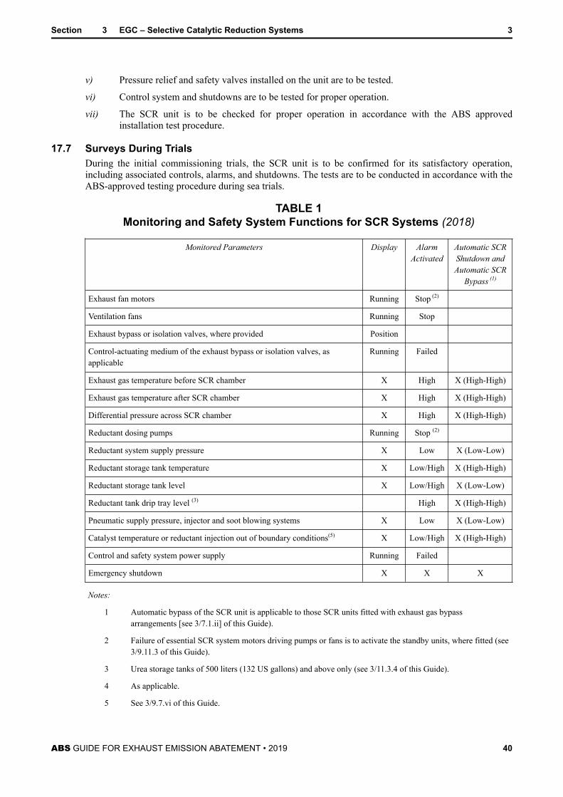
TABLE 1 Monitoring and Safety System Functions for SCRSystems............................................................................... 40
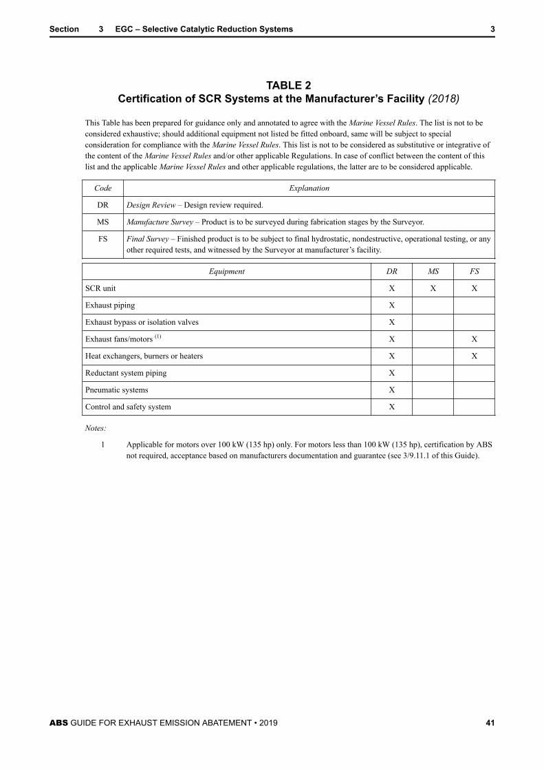
TABLE 2 Certification of SCR Systems at the Manufacturer’sFacility..................................................................................41
SECTION 4 EGC – Exhaust Gas Recirculation Systems....................................421 General.........................................................................................423 Plans and Data to be Submitted...................................................425 EGR Operation and Maintenance Manuals..................................437 EGR System Configuration and Vessel Integration......................43
7.1 General............................................................................ 437.3 Compatibility with the Engine...........................................43
ABS GUIDE FOR EXHAUST EMISSION ABATEMENT • 2019 v
7.5 Redundancy.....................................................................447.7 Essential Services........................................................... 447.9 Prevention of Flooding.....................................................447.11 Inclinations.......................................................................44
9 EGR System Equipment ..............................................................449.1 Pumps/Blowers................................................................449.3 Heat Exchangers/EGR Exhaust Gas Coolers................. 459.5 Chemical Treatment System............................................459.7 Electrical System............................................................. 45
11 EGR System Piping .....................................................................4611.1 Exhaust Gas Piping Systems.......................................... 4611.3 Washwater Piping............................................................4611.5 Chemical Treatment Piping Systems...............................4711.7 Residue System...............................................................50
13 Control, Alarm, and Monitoring System........................................5013.1 General............................................................................ 5013.3 Control and Monitoring System....................................... 5113.5 Safety Shutdown System.................................................51
15 FMEA Integration Test.................................................................. 5117 Surveys During Construction........................................................52
17.1 General............................................................................ 5217.3 Surveys at Manufacturer’s Facility...................................5217.5 Surveys During Installation.............................................. 5217.7 Surveys During Trials.......................................................52
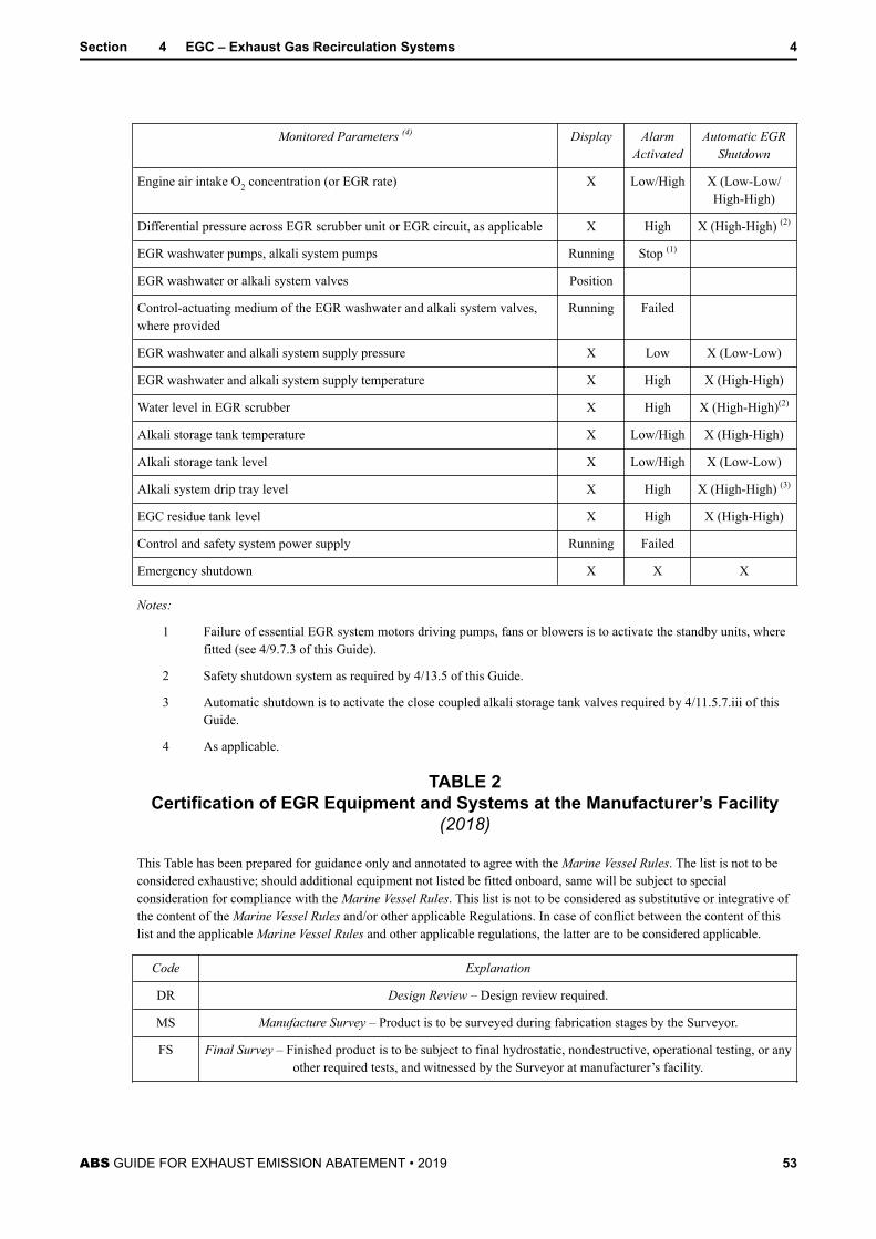
TABLE 1 Monitoring and Safety System Functions for EGRSystems............................................................................... 52
TABLE 2 Certification of EGR Equipment and Systems at theManufacturer’s Facility......................................................... 53
SECTION 5 Exhaust Emission Monitoring Systems...........................................551 General.........................................................................................553 Plans and Data to be Submitted...................................................555 EEMS Operation and Maintenance Manuals................................567 Exhaust Emission Monitoring Systems.........................................56
9 EEMS Equipment......................................................................... 569.1 General............................................................................ 569.3 Sample Probes for Gaseous Emissions.......................... 569.5 Sample Handling............................................................. 579.7 Analyzer Specifications and Calibration.......................... 579.9 Data Recording and Processing Device.......................... 579.11 Pneumatic Systems......................................................... 57
ABS GUIDE FOR EXHAUST EMISSION ABATEMENT • 2019 vi
11 Monitoring System .......................................................................5811.1 General............................................................................ 5811.3 Monitoring System........................................................... 58
13 Surveys During Construction........................................................5813.1 General............................................................................ 5813.3 Surveys During Installation.............................................. 5813.5 Surveys During Trials.......................................................58
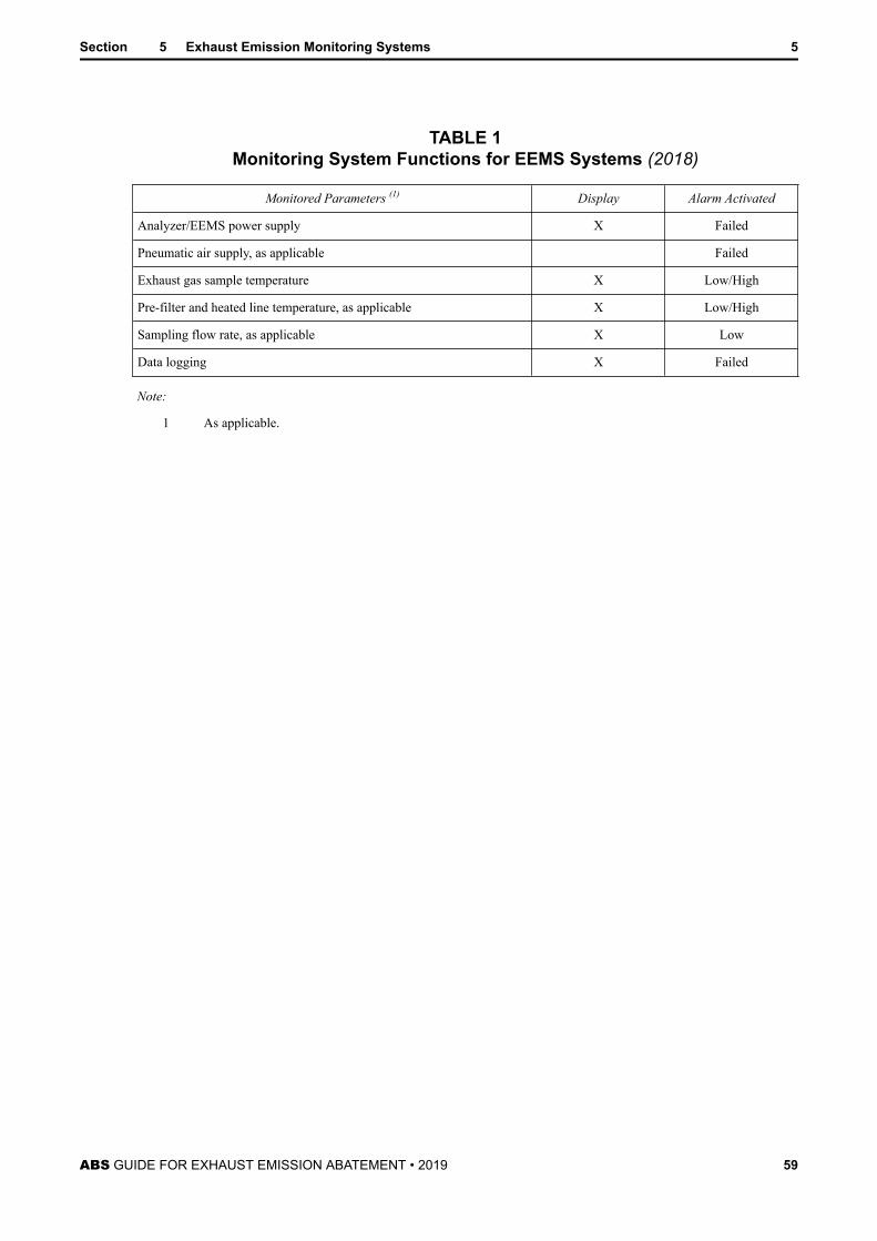
TABLE 1 Monitoring System Functions for EEMS Systems................59
SECTION 6 Surveys After Construction and Maintenance of Class................. 601 General.........................................................................................60
5.1 Annual Surveys................................................................615.3 Special Periodical Survey................................................ 63
7 Alternative Surveys.......................................................................64
ABS GUIDE FOR EXHAUST EMISSION ABATEMENT • 2019 vii
S E C T I O N 1 General
1 Scope and Application (2018)This Guide is to be applied to exhaust emission abatement systems fitted to ABS classed vessels andcovers SOx scrubbers, SCR systems and EGR arrangements, together with Exhaust Emissions MonitoringSystems (EEMS) fitted in conjunction with the aforementioned emission abatement systems, or installed asan alternative Onboard NOx Verification Procedure in accordance with the Direct Measurement andMonitoring Method of the NOx Technical Code.
The optional exhaust emission abatement notations detailed under 1/9.3 through 1/9.9 will be assigned to avessel upon request and where the exhaust emission abatement system has been verified to be incompliance with the applicable requirements of this Guide. Where a notation has not been requested, theexhaust emission abatement system is to be verified to be in compliance with the minimum requirementsprescribed under 1/9.11 of this Guide. This is applicable to new construction and existing vesselmodifications.
3 General (2018)This Guide focuses on the safety and reliability aspects of exhaust emission abatement equipment that fallwithin the scope of traditional Classification requirements and is to be applied to those Exhaust GasCleaning (EGC) systems covering SOx scrubbers, SCR systems, and EGR arrangements. SOx scrubbersand SCR units are generally installed downstream of the Fuel Oil Combustion Unit (FOCU) and areconsidered secondary aftertreatment systems. Compatibility of these EGC systems with the FOCU is to beverified as part of the approval process preferably in consideration of, the FOCU equipment manufacturer.A Low Pressure SCR system is one where the SCR reaction chamber and catalysts are integrated after theexhaust gases have passed through the turbocharger. In the case of EGR systems, or SCR systems fittedbefore an engine turbocharging system (High Pressure SCR), these are considered primary exhaustemission reduction techniques forming part of the total engine design and as such are to be integrated bythe engine designer or a third party under the authorization of the engine designer. Those applicablerequirements for EGR and SCR systems contained within this Guide are supplementary to, and to beapplied in association with, the requirements for internal combustion engines under Section 4-2-1 of theABS Rules for Building and Classing Marine Vessels (Marine Vessel Rules).
This Guide is focuses on those systems designed to reduce gaseous exhaust emissions species legislatedthrough the International Maritime Organization (IMO) Annex VI Regulations 13 and 14 for nitrogenoxide (NOx) emissions from diesel engines and sulfur oxide (SOx) emissions from all fuel burningequipment on board. Acceptance of a SOx exhaust gas cleaning system under MARPOL Annex VI, as analternative means of compliance through Regulation 4, is subject to approval by the flag Administration ofthe vessel.
The regulatory requirements covering the air emissions performance, testing, statutory certification, andstatutory survey aspects are regulated through Annex VI in association with any other applicable IMOGuidelines. At the time of issuance of this Guide, the applicable Guidelines for Selective CatalyticReduction are IMO Resolution MEPC.291(71) – 2017 Guidelines Addressing Additional Aspects to theNOx Technical Code 2008 With Regard to Particular Requirements Related to Marine Diesel EnginesFitted With Selective Catalytic Reduction (SCR) Systems, adopted 7 July 2017. The applicable Guidelinesfor SOx exhaust gas cleaning systems are IMO Resolution MEPC.259(68) – 2015 Guidelines for ExhaustGas Cleaning Systems, adopted 15 May 2015. This Guide is intended to cover only the Classification
ABS GUIDE FOR EXHAUST EMISSION ABATEMENT • 2019 8
aspects, and the statutory approval may be made by ABS as a separate parallel process in the capacity of aRecognized Organization (RO) for the vast majority of flag Administrations, when authorized by the flag.
Individual flag Administrations may have in place additional requirements pertaining to the operation ofEGC systems for vessels operating in their territorial waters, in particular with respect to those systemsproducing a washwater discharge associated with the exhaust gas cleaning process. These requirementsmay necessitate additional vessel features, performance standards, equipment, reporting and recordkeeping, or operational practices that are not covered by the IMO regulations or this Guide. Accordingly,any party selecting an exhaust emission abatement system for a particular vessel is encouraged to verifythe need for any additional or specific arrangements to meet the requirements of the vessel flagAdministration, coastal state or port Authorities.
5 Objectives (2018)The objective of this Guide is to provide criteria for the design, construction, installation, survey, andoperation of machinery and equipment associated with exhaust emission abatement systems in order tominimize risks to the vessel, crew, and the environment. The intent is that these requirements supplementthe statutory emissions performance testing, survey, and certification requirements of the aforementionedIMO Regulations and Guidelines. Detailed requirements are provided in each of the Sections of this Guideto achieve this objective in accordance with the following key principles and requirements:
● Installation and operation of an exhaust emission abatement system is to be compatible with the fueloil combustion unit and not to cause any adverse effects on the FOCU performance, such as excessiveback pressures/temperatures, or is to incorporate additional features to mitigate such effects.
● Materials of construction and workmanship are to be in accordance with the requirements of of theABS Rules for Materials and Welding (Part 2) or to an alternate standard specifically approved inaccordance with the design of the exhaust emission abatement system.
● Exhaust emission abatement systems are to be designed to enable continued operation of the FOCU atthe times the EGC system is not in operation, either through operational selection, equipment failure,or system deterioration through partial blocking/clogging, or be designed with suitable exhaust bypassarrangements to enable continued operation of the FOCU.
● Where applicable, exhaust emission abatement units and their associated equipment and systems are tobe designed to minimize the risks associated with the storage, handling, consumption, and disposal ofhazardous or non-hazardous chemicals or consumables essential for operation of the EGC system.Appropriate personnel protection arrangements and equipment are to be provided.
● As applicable, means are to be provided to suitably mitigate the risk to the FOCU or vessel frominternal flooding associated with water scrubbing systems.
● Redundancy of equipment is to be provided for those rotating and reciprocating components that formpart of the exhaust emission abatement unit supplementary systems, such as pumps, fans, blowers,etc., and due diligence is to be exercised and demonstrated in the assessment of critical components,equipment, and systems. Alternatively the carriage of spare parts onboard or alternative means ofcompliance or operation will be accepted to meet this objective.
● Means are to be provided to prevent the passage or leakage of exhaust gases to other equipment orspaces that may then pose a safety risk to that equipment or a health risk to the vessel’s crew orpassengers.
● Exhaust emission abatement systems are to be arranged for easy inspection and maintenance andwhere applicable the ability to replace internal components is to be provided.
● Hot surfaces of exhaust emission abatement units or their associated equipment or systems likely tocome into contact with the crew during operation are to be suitably guarded or insulated. Where thesurface temperatures are likely to exceed 220°C (428°F), they are to be suitably insulated with non-combustible materials.
Section 1 General 1
ABS GUIDE FOR EXHAUST EMISSION ABATEMENT • 2019 9
● Appropriate storage and operational arrangements and procedures are to be in place for any specializedor hazardous gases used in exhaust emission abatement units or monitoring systems.
● Automation, instrumentation, monitoring, and control systems are to be provided to facilitateautomated operation and monitoring of exhaust emission abatement systems.
● Operation and maintenance manuals are to be provided for all exhaust emission abatement units andassociated equipment and systems to facilitate handling, operation, maintenance, and repair.
● Means are to be provided for the safe storage and disposal of any exhaust residues associated withoperation of the exhaust emission abatement system.
● Fire protection, detection and extinguishing arrangements are to be provided to protect the vessel andcrew from possible fire hazards associated with the operation of exhaust emission abatement units andtheir associated systems together with any applicable hazardous or non-hazardous consumables.
7 Definitions and Abbreviations
7.1 COCarbon Monoxide.
7.3 CO2
Carbon Dioxide.
7.5 EGCExhaust Gas Cleaning.
7.7 EGRExhaust Gas Recirculation. The process whereby part of the exhaust gas flow is redirected back to thecombustion cylinder of an engine for the purposes of reducing NOx emissions.
7.9 EEMSExhaust Emissions Monitoring System.
7.11 Fuel Oil Combustion Unit (FOCU)Any engine, boiler, gas turbine, or other fuel oil fired equipment, excluding shipboard incinerators.
7.13 HCHydrocarbon.
7.15 MARPOLThe IMO International Convention for the Prevention of Pollution from Ships, 1973, as modified by theprotocol of 1978.
7.17 MSDSMaterial Safety Data Sheet. Sometimes referred to as Safety Data Sheet (SDS) or Product Safety DataSheet (PSDS).
7.19 NOx
Nitrogen Oxides. Predominantly containing NO and NO2 components and typically calculated as the totalweighted emission with mass reference for NO2 and determined using the relevant test cycles andmeasurement methods of the IMO NOx Technical Code or ISO 8178.
Section 1 General 1
ABS GUIDE FOR EXHAUST EMISSION ABATEMENT • 2019 10
7.21 O2
Oxygen.
7.23 PMParticulate Matter.
7.25 Recognized Organization (RO)An organization that has been delegated by an Administration to undertake surveys and certification on theAdministrations behalf in accordance with the IMO guidelines adopted by Resolution A.739(18), asamended, and the specifications adopted by IMO Resolution A.789(19), as amended.
7.27 Recognized StandardAn international or national standard acceptable to ABS.
7.29 RulesThe applicable edition of the ABS Rules for Building and Classing Marine Vessels (Marine Vessel Rules).
7.31 SCR (2018)Selective Catalytic Reduction. An exhaust aftertreatment system whereby the exhaust gases are mixed witha reductant, such as ammonia introduced in a urea/water solution, and passed over a catalyst, such asvanadium, located in the downstream exhaust system for the purposes of NOx reduction of the exhaustgases.
A High Pressure SCR is an SCR system integrated onto an engine before the exhaust gas passes throughthe turbo charger.
A Low Pressure SCR is an SCR system integrated onto an engine after the exhaust gas passes through theturbo charger.
7.33 SOx
Sulfur Oxide emissions. All sulfur emissions from fuel oil combustion machinery are caused by thecombustion reactions with the sulfur introduced by the fuel which predominately include SO2 and SO3emissions and are typically quantified as SO2 emissions.
7.35 Urea (2018)The most common reductant source used in SCR applications is urea, where ammonia and deionized waterare mixed, typically in 32.5% concentrations for automotive use, commonly known as AUS-32 or DieselExhaust Fluid, and 40% concentration in the marine industry. Where the term urea is used in this Guide,this refers to 40% marine grade urea, commonly known as AUS-40.
9 Classification Notations
9.1 General (2018)The optional vessel notations detailed under 1/9.3 through 1/9.9 of this Guide will be assigned uponrequest and where single or multi exhaust emission abatement systems are found to be in compliance withthe applicable requirements of this Guide.
9.3 EGC-– SOx ScrubbersWhere an exhaust gas cleaning system primarily designed for the reduction of SOx emissions using exhaustgas scrubbing is designed, constructed, and tested in accordance with Section 2 of this Guide, the EGC-SOx notation may be assigned.
Section 1 General 1
ABS GUIDE FOR EXHAUST EMISSION ABATEMENT • 2019 11
9.5 EGC – SCR SystemsWhere an exhaust gas cleaning system primarily designed for the reduction of NOx emissions by the use ofSelective Catalytic Reduction catalysts is designed, constructed, and tested in accordance with Section 4 ofthis Guide, the EGC-SCR notation may be assigned.
9.7 EGC – EGR Systems (2018)Where an exhaust gas cleaning system primarily designed for the reduction of NOx emissions by the use ofexhaust gas recirculation is designed, constructed, and tested in accordance with Section 4 of this Guide,the EGC-EGR notation may be assigned. This notation is intended to be applied to those EGR systemsthat incorporate extensive off-engine systems designed for the purposes of removing the sulfur by-productsfrom the exhaust gases that originate from the fuel and incorporate, for example, water scrubbing andwater cleaning systems. Where a water treatment system is incorporated in the EGR system, the washwaterdischarge criteria is to meet the requirements of IMO Resolution MEPC.184(59).
For those engine designs that incorporate all EGR system components within the base engine design and,for example, may be primarily designed for use with low sulfur fuels, then the EGC-EGR notation maynot be assigned.
The EGR version of the engine is to be approved by incorporation to the existing internal combustionengine approval.
9.9 Exhaust Emission Monitoring SystemsThe notation for an exhaust emissions monitoring system may be assigned to a vessel fitted with, orwithout, an exhaust emission abatement system. Where a permanently installed exhaust emissionmonitoring system is designed, constructed and tested in accordance with Section 5 of this Guide theEEMS notation may be assigned.
9.11 Minimum Requirements for Systems Where EGC Notation is not Requested (2018)Where a vessel is fitted with an exhaust emission abatement system and the optional vessel notationsdetailed under 1/9.3 through 1/9.9 are not requested, the installed exhaust emission abatement system is tocomply with the minimum requirements prescribed in 1/15 TABLE 1 and is to be verified by an ABSSurveyor during installation. This is applicable to new construction and existing vessel modifications.
11 Operating and Maintenance Instruction ManualsDetailed instruction manuals are to be provided onboard, covering the operations, safety, and maintenancerequirements and occupational health hazards relevant to the particular exhaust emission abatement unitand associated systems.
The manuals are to include, but not be limited to, the regular testing and maintenance procedures andschedules for the monitoring systems, safety shut-off systems, and the integrity of backup systems togetherwith identification of the relevant responsible parties.
In addition, there is further guidance regarding the contents of the operating and maintenance manuals ineach of the individual Sections of this Guide. Reference is to be made to the requirements in each Sectionof this Guide.
13 AlternativesEquipment, components, and systems for which there are specific requirements in this Guide, or itsassociated references, may incorporate alternative arrangements or comply with the requirements ofalternative recognized standards, in lieu of the requirements in this Guide. This, however, is subject to suchalternative arrangements or standards being determined by ABS as being not less effective than the overallsafety requirements of this Guide or associated references. Where applicable, requirements may beimposed by ABS in addition to those contained in the alternative arrangements or standards so that the
Section 1 General 1
ABS GUIDE FOR EXHAUST EMISSION ABATEMENT • 2019 12
intent of this Guide is met. In all cases, the equipment, component, or system is subject to design review,survey during construction, tests, and trials, as applicable, by ABS for purposes of verification of itscompliance with the alternative arrangements or standards. The verification process is to be to the extent asintended by this Guide.
15 CertificationDesign review, survey, testing, and the issuance of reports or certificates constitute the certification ofmachinery, equipment, and systems (see also 4-1-1/3 of the Marine Vessel Rules). There is guidance on thecertification requirements for machinery, equipment, and systems in each of the applicable individualSections of this Guide. The applicable edition of the Marine Vessel Rules is to be used in association withthe subject Guide.
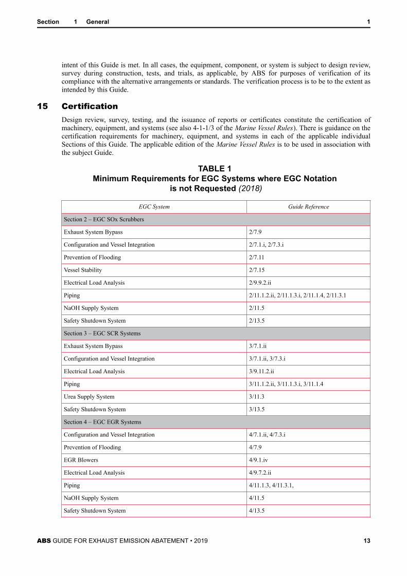
TABLE 1 Minimum Requirements for EGC Systems where EGC Notation
is not Requested (2018)
EGC System Guide Reference
Section 2 – EGC SOx Scrubbers
Exhaust System Bypass 2/7.9
Configuration and Vessel Integration 2/7.1.i, 2/7.3.i
Configuration and Vessel Integration 3/7.1.ii, 3/7.3.i
Electrical Load Analysis 3/9.11.2.ii
Piping 3/11.1.2.ii, 3/11.1.3.i, 3/11.1.4
Urea Supply System 3/11.3
Safety Shutdown System 3/13.5
Section 4 – EGC EGR Systems
Configuration and Vessel Integration 4/7.1.ii, 4/7.3.i
Prevention of Flooding 4/7.9
EGR Blowers 4/9.1.iv
Electrical Load Analysis 4/9.7.2.ii
Piping 4/11.1.3, 4/11.3.1,
NaOH Supply System 4/11.5
Safety Shutdown System 4/13.5
Section 1 General 1
ABS GUIDE FOR EXHAUST EMISSION ABATEMENT • 2019 13
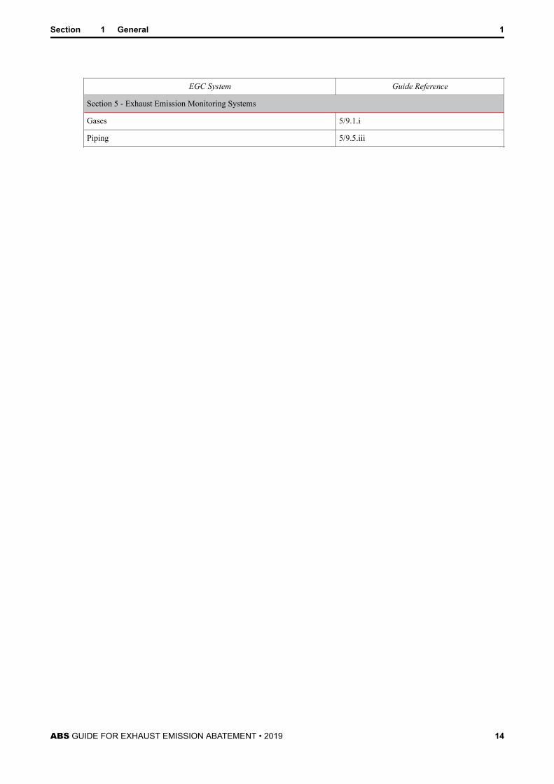
EGC System Guide Reference
Section 5 - Exhaust Emission Monitoring Systems
Gases 5/9.1.i
Piping 5/9.5.iii
Section 1 General 1
ABS GUIDE FOR EXHAUST EMISSION ABATEMENT • 2019 14
S E C T I O N 2 EGC – SOx Scrubbers
1 General (2018)This Section provides requirements on the arrangements and system design for exhaust gas cleaningsystems designed primarily for the removal of SOx emissions, or SOx scrubbers, as they are commonlyknown. The intent is that these requirements supplement the statutory emissions performance testing,survey, and certification requirements of the applicable IMO Regulations and Guidelines. At the time ofissuance of this Guide, the applicable Guidelines for SOx exhaust gas cleaning systems are IMO ResolutionMEPC.259(68) – 2015 Guidelines for Exhaust Gas Cleaning Systems, adopted 15 May 2015. The statutoryapproval aspects may be made by ABS as a separate parallel process in the capacity of a RecognizedOrganization for the vast majority of flag Administrations, when authorized by the flag.
3 Plans and Data to be Submitted (2018)Plans and specifications covering the SOx scrubber arrangements are to be submitted and are, as applicable,to include:
● General arrangement of the SOx scrubber installation, layout, and systems
● Documentation detailing the SOx scrubber specification
● Analyses demonstrating compatibility of the scrubber with the fuel oil combustion units (see 2/7.3 ofthis Guide)
● Hull plans showing the foundation and attachments to the vessel’s structure, including scantlings,welding details, and foundation details of principal components
● Documentation detailing the effect on Load Line and Stability of the exhaust emission abatementsystem (see 2/7.15 of this Guide)
● Material specifications for the scrubber unit, pumps, valves, storage/process tanks, residue tanks,piping, distribution systems, separators, and associated components, including a corrosion assessmentdetailing the corrosive effect of system liquids, vapors, and gases on the materials used in the exhaustemission abatement system
● Arrangement and capacity of tanks for storage, chemicals, process washwater, exhaust gas cleaningresidues, etc.
● Details of all piping systems, including details of piping and associated components, design pressures,temperatures, insulation, and drip trays, where applicable
● Descriptions and schematic diagrams for the control and monitoring systems, including set points forabnormal conditions and details of the location and positions where exhaust emission monitoring andwashwater monitoring systems are to be located
● Details of all electrical equipment installed for the SOx scrubber unit and associated systems, includingcomputer-based systems
● Failure Modes and Effects Analysis (FMEA) to determine possible failures and their effects in the safeoperation of the SOx scrubber [see 2/13.1 of this Guide]
● Emergency shutdown arrangements
● SOx scrubber unit FMEA integration test report (see 2/15 of this Guide)
ABS GUIDE FOR EXHAUST EMISSION ABATEMENT • 2019 15
● Operating and maintenance instruction manuals, including MSDS sheets and details for handling ofhazardous and non-hazardous chemicals used in the SOx exhaust emission abatement system
● Testing procedures during installation and commissioning trials
5 EGC-SOx System Operation and Maintenance ManualsIn accordance with 1/11 of this Guide, detailed instruction manuals are to be provided onboard, coveringthe operations, safety, and maintenance requirements and occupational health hazards relevant to the SOxexhaust emission abatement equipment and associated systems.
These manuals are to include, but not necessarily be limited to, the procedures and schedules for operation,inspection, testing and maintenance of the SOx scrubber and associated systems, the regular testing andmaintenance procedures for the monitoring systems, safety shutoff systems, and the integrity of backupsystems, together with special instructions for the bunkering, storage, and use of hazardous and non-hazardous chemicals that may be used in the exhaust emission abatement system and identification of therelevant responsible parties.
The manuals are to be submitted for review solely to verify the presence of all the information required bythis Section.
7 EGC-SOx System Configuration and Vessel Integration
7.1 General (2018)i) Exhaust emission abatement systems are to be designed to enable continued operation of the
FOCU at the times the EGC system is not in operation, either through operational selection,equipment failure, or system deterioration through partial blocking/clogging.
ii) The exhaust systems from a number of fuel oil combustion units may be led to a common SOxscrubber unit, sometimes known as an integrated scrubber (see 2/11.1.3 of this Guide).
iii) The response of the mechanical and electrical systems of the first SOx scrubber unit in a particulardesign series is to be demonstrated by the FMEA integration test of 2/15 of this Guide.
7.3 Compatibility with Fuel Oil Combustion Units (2018)i) Installation and operation of an exhaust emission abatement system is to be compatible with the
fuel oil combustion unit(s) and is not to cause any adverse effects on the FOCU performance suchas excessive back pressures or high temperatures during operation.
ii) Details are to be submitted demonstrating the exhaust flow compatibility of the EGC unit with theconnected FOCUs over the whole operational range of the fuel oil combustion units. This datashould demonstrate that the operating parameters of the oil burning units do not exceed theapproved design limits with the EGC system in operation. In the case of integrated scrubbers, thiscompatibility evaluation is to show that the EGC unit is capable of accommodating the maximumcombined exhaust flows of all the connected oil burning equipment for the worst case scenario forthat particular ship arrangement and operational profile. Consideration will be given to those EGCunits that incorporate extractive exhaust fans to maintain the FOCU operating parameters withinthe approved design limits.
It is to be noted that exhaust emission abatement systems that cause diesel engines to operateoutside the exhaust backpressure limits detailed in the approved IMO Annex VI Regulation 13Technical Files may invalidate the emissions certification and will require a re-approval of theengine NOx certification by the Administration or RO responsible for the original certification.
Section 2 EGC – SOx Scrubbers 2
ABS GUIDE FOR EXHAUST EMISSION ABATEMENT • 2019 16
7.5 RedundancyRedundancy of equipment is to be provided for those rotating and reciprocating components that form partof the exhaust emission abatement unit essential supplementary systems, such as pumps, fans, blowers, etc.(see 2/9.1 and 2/9.9.3 of this Guide).
Consideration will be given to alternative means of compliance or operation to meet this objective on acase-by-case basis. As applicable, documentation is to be submitted demonstrating that the reliability ofthe system or component provides continued serviceability of the exhaust emission abatement system orthe alternative means of operation provides continued compliance with the statutory environmentalrequirements, without compromising the vessel propulsion and maneuvering capability. The provision ofadequate fuel tank capacity for low sulfur fuels, alternative operating modes or carriage of sufficient spareparts onboard are examples of vessel specific arrangements that may be considered by ABS as meeting thisobjective and should be justified with reference to the FMEA required by 2/13.1 of this Guide.
7.7 Essential ServicesFor the purposes of design, construction, testing, and survey, EGC units and associated components andsystems are considered secondary essential services in accordance with 4-8-1/7.3.3 of the Marine VesselRules.
7.9 Exhaust Bypass/Dry Running of Scrubbers (2018)EGC units that incorporate a wet washwater scrubbing process are to be capable of being operated withoutthe washwater system in operation, without sustaining thermal damage, or are to be installed with anexhaust bypass arrangement or changeover system to enable continued operation of the fuel oil combustionunits in the event the exhaust emission abatement washwater system is not in operation, either throughoperational selection or equipment failure. As applicable, evidence of material suitability is to be submittedfor dry running of SOx scrubbers.
All EGC units fitted to single main propulsion engines are to be installed with an exhaust bypassarrangement unless arranged for unrestricted flow of exhaust gas and with no risk of causing failure of themain propulsion engine.
7.11 Prevention of Fuel Oil Combustion Unit Floodingi) For EGC units that incorporate a wet washwater scrubbing process, arrangements are to be
provided to prevent the ingress of scrubber washwater into the fuel oil combustion unit under anycircumstance. In general, the design of the inlet exhaust piping is to be arranged to prevent directfree flow of washwater back to the FOCU.
ii) Monitoring, alarm, and shutdown arrangements are to be provided to prevent an abnormal rise ofwashwater level in the scrubber reaction chamber.
7.13 InclinationsExhaust emission abatement systems are to be designed for proper operation at the inclinationrequirements of 4-1-1/7.9 of the Marine Vessel Rules.
7.15 Vessel Stabilityi) For those existing ships fitting an exhaust emission abatement system as a retrofit conversion, a
revision of the stability calculations may be required based on the additional weights of the EGCsystem and increased wind profile. In general, if the change in lightship displacement exceeds 2%(excluding any certified weights, if any) of the lightship displacement from the most recentapproved lightship data and/or the change in lightship Longitudinal Center of Gravity (LCG),relative to the most recent approved lightship data, exceeds 1.0% of the Length BetweenPerpendiculars (LBP), a stability test may be required on the vessel and stability calculationswould need to be revised to indicate the changes. Where a ship is within these limits, immediateupdate of the Stability Booklet may not be required if there is sufficient margin in the conditions
Section 2 EGC – SOx Scrubbers 2
ABS GUIDE FOR EXHAUST EMISSION ABATEMENT • 2019 17
contained in the booklet. In this case, the principal particular page would need to be updated, andthe ship would be required to use the latest lightship properties when assessing new conditions.
ii) Documentation detailing the effect on Load Line and Stability of the exhaust emission abatementsystem, in accordance with the guidance of 2/7.15.i of this Guide, is to be submitted.
7.17 Inspection and Maintenance (2018)EGC units are to be arranged for easy inspection and maintenance with at least one inspection port or hatchavailable for internal inspection of the main reaction chamber, and where applicable the ability to replaceinternal components is to be provided.
9 EGC-SOx System Equipment
9.1 Pumps/Fansi) Where provided, SOx scrubber washwater, circulation, discharge, etc., pumps, essential for the
continual operation of the EGC system, are to be tested and certified in accordance with 4-6-1/7.3of the Marine Vessel Rules. This is applicable to exhaust emission abatement systems connected tofuel oil combustion units rated at 2250 kW and above or internal combustion engines havingcylinders of more than 300 mm (11.8 in.) bore.
ii) Unless alternative means of compliance in accordance with 2/7.5 of this Guide are applicable,redundant washwater, circulation, discharge, etc., pumps, essential for the continual operation ofthe EGC water systems, are to be provided. There are to be at least two of these essential pumps,and the capacity of the pumps, with any one pump out of service, is to be sufficient for continuousoperation of the exhaust emission abatement system at full rating. See also 2/9.9.3 of this Guide.
For vessels fitted with two or more identical exhaust emission abatement systems, the provision ofa common standby pump (for each essential system) capable of serving all EGC units will sufficerather than providing individual standby pumps for each EGC unit.
iii) Unless alternative means of compliance in accordance with 2/7.5 of this Guide are applicable andwhere exhaust fans form part of the EGC system and are essential for continual operation of theexhaust emission abatement system at full rating, such fans are to be installed in a redundantarrangement. The number and power of the fans should be such that if one fan, or a group of fans,is out of service, the capacity of the remaining fan(s) is not to be less than 100% of the totalrequired.
9.3 Exhaust Plume Heaters (2018)i) Where provided, heat exchangers within the exhaust are to be designed, constructed, and certified
in accordance with Section 4-4-1 of the Marine Vessel Rules.
ii) Where the introduction of hot air to the exit exhaust gases is used on exhaust emission abatementsystems, the details of this auxiliary system are to be submitted for review and approval on a case-by-case basis.
9.5 Chemical Treatment SystemThe specific requirements for chemical treatment system components are given under 2/11.5 of this Guide.
9.7 Dry Scrubber Consumable Handling Equipmenti) For dry type exhaust emission abatement systems, details of the granulate supply and discharge
systems are to be submitted.
ii) Unless alternative means of compliance in accordance with 2/7.5 of this Guide are applicable,drive arrangements for the exhaust cleaning reductant consumable are to be arranged in aredundant arrangement.
Section 2 EGC – SOx Scrubbers 2
ABS GUIDE FOR EXHAUST EMISSION ABATEMENT • 2019 18
9.9 Electrical SystemThe electrical system and electrical equipment requirements in this Paragraph are to be applied inassociation with the requirements of Part 4, Chapter 8 of the Marine Vessel Rules.
9.9.1 Electrical Motors and ControllersMotors and motor controllers of 100 kW (135 hp) and over are to be certified in accordance withPart 4, Chapter 8 of the Marine Vessel Rules.
9.9.2 Electrical Load Analysis (2018)i) The number and capacity of generators are to be sufficient under normal seagoing
conditions with one generator in reserve to carry those loads for essential services and forminimum comfortable conditions of habitability as per 4-8-2/3.1.1 of the Marine VesselRules.
ii) The electrical loads associated with the SOx exhaust gas cleaning system are to beincluded in the electric-plant load analysis required by 4-8-1/5.1.5 of the Marine VesselRules.
9.9.3 Standby Pump/Fan Arrangementsi) In the event of failure of the essential exhaust emission abatement system pumps or fans,
the standby pump or fan required by 2/9.1 of this Guide, where provided, is to beautomatically started and put into service. This failure is to be alarmed at the local andremote control station(s), as applicable.
ii) Where provided, each standby pump or fan is to be fed from separate sections of theswitchboard such that in the event of failure of one section of the switchboard the standbypump or fan may be fed from the other separate section of the switchboard.
9.9.4 Circuit Protection Devices and CompatibilityCircuit breakers are to be installed for miscellaneous EGC system electrical loads and are to becompatible with the prospective short circuit current level calculated at the switchboards.
11 EGC-SOx System Piping
11.1 Exhaust Gas Piping Systems11.1.1 Exhaust Gas Piping/Scrubber Materials and Installation
i) Exhaust gas piping materials located before the SOx scrubber unit may be of the samematerial specification as the standard exhaust gas piping.
ii) The sections of the scrubber that are subjected to washwater (e.g., the interior reactionchamber or washwater piping/nozzles, etc.) are to be constructed of suitable corrosionresistant materials.
iii) Exhaust gas piping materials used after the SOx scrubber unit are to be of a corrosionresistant material such as stainless steel.
iv) The exhaust piping systems for exhaust emission abatement systems are to meet theapplicable requirements of 4-6-2/9 and 4-6-5/11 of the Marine Vessel Rules.
v) Exhaust gas piping and piping components constructed of non-metallic materials are tocomply with 4-6-2/3 of the Marine Vessel Rules and to be specifically approved for theintended application.
11.1.2 Exhaust Gas Piping Valvesi) Valves used in the exhaust system of emission abatement systems are to meet the
requirements of 4-6-2/5.11 of the Marine Vessel Rules and, in general, are to comply witha recognized standard and are to be permanently marked in accordance with therequirements of that standard.
Section 2 EGC – SOx Scrubbers 2
ABS GUIDE FOR EXHAUST EMISSION ABATEMENT • 2019 19
The valves are to be constructed of corrosion resistant materials.
ii) Isolation and bypass valves used in EGC system exhaust piping systems are to prevent thepassage of exhaust gases to other fuel oil combustion units or machinery spaces.
Where bypass arrangements for the SOx scrubber unit are provided, the isolation andbypass valves are to be arranged in an interlocked, fail safe manner, such that free flow ofexhaust gases to the atmosphere is possible at all times, either through the scrubber unit orthrough the bypass. Bypass valves are to be provided with a local position indicator.
iii) Valves are to be installed in accessible locations, clear of or protected from obstructions,moving equipment, and hot surfaces, in order to permit regular inspection and/or periodicservicing.
11.1.3 Interconnections of Exhaust Gas Piping (2018)i) Normally, exhaust pipes from internal combustion engines and flue gas pipes from oil-
fired boilers are to be routed separately and are not to be interconnected. However,interconnected exhaust piping systems to a common exhaust emission abatement unitmay be accepted subject to the arrangements preventing the passage or leakage of exhaustgases to other equipment or spaces that may then pose a safety risk to that equipment orhealth risk to the vessel’s crew or passengers. The return of exhaust gas between arunning fuel oil combustion unit to another stopped, or in operation, FOCU is to beprevented.
ii) The integrated EGC system is to be designed not to exceed the backpressure limitsspecified by the connected engines or boilers. Fans installed for this purpose are to meetthe redundancy requirements of 2/9.1.iii of this Guide.
11.1.4 Exhaust Gas Scrubber and Scrubber Piping InsulationHot surfaces of exhaust emission abatement units or their associated equipment or systems likelyto come into contact with the crew during operation are to be suitably guarded or insulated. Wherethe surface temperatures are likely to exceed 220°C (428°F) and where any leakage, underpressure or otherwise, of fuel oil, lubricating oil, or other flammable liquid is likely to come intocontact with the EGC unit or exhaust pipes, these surfaces are to be suitably insulated with non-combustible materials that are impervious to such liquids. Insulation material not impervious to oilis to be encased in sheet metal cladding or an equivalent impervious sheath.
11.3 Washwater Piping11.3.1 Piping and Connections
i) In general, pipe fittings and joints are to meet the requirements of the Marine Vessel Rulesfor certification in 4-6-1/7.1, materials in 4-6-2/3, and design in 4-6-2/5.5 and 4-6-2/5.15,subject to the limitations in 4-6-5/7.3.3 TABLE 3.
Molded non-metallic expansion joints, where used, are to be of an approved type (see4-6-2/5.8.1, 4-6-2/9.19 TABLE 2 of the Marine Vessel Rules for Cu and Cu Alloy and4-6-2/9.19 TABLE 5A of the Marine Vessel Rules for pipe thickness).
ii) The piping material for the corrosive scrubber washwater system is to be selected basedon the corrosive nature of the liquid media.
iii) Pipes and piping components made of thermoplastic or thermosetting plastic materials,with or without reinforcement, may be used in piping systems subject to compliance withthe requirements of Section 4-6-3 of the Marine Vessel Rules. For the purpose of theseRules, “plastic” means both thermoplastic and thermosetting plastic materials, with orwithout reinforcement, such as polyvinyl chloride (PVC) and fiber reinforced plastics(FRP). Plastic washwater piping is to meet Level 3 fire endurance testing requirements(see 4-6-3/5.11 of the Marine Vessel Rules).
Section 2 EGC – SOx Scrubbers 2
ABS GUIDE FOR EXHAUST EMISSION ABATEMENT • 2019 20
iv) Flexible hoses are to comply with the requirements of 4-6-2/5.7 of the Marine VesselRules.
11.3.2 Remote Control Valvesi) Upon loss of control power, the remote control valves are to remain in the last ordered
position, provided there is a readily accessible means to manually close the valves, or areto fail safe in accordance with the FMEA.
ii) Remote control valves are to be clearly identified and are to be provided with positionindicators at the local and EGC system remote control station, as applicable.
iii) Valves are to be installed in accessible locations, clear of or protected from obstructions,moving equipment, and hot surfaces in order to permit regular inspection and/or periodicservicing.
11.3.3 Overboard Discharges (2018)i) Overboard discharges of any exhaust emission abatement system are not to be
interconnected to other systems.
ii) Special attention is to be paid to the corrosion resistivity of EGC washwater overboarddischarge piping.Where applicable, adequate arrangements are to be provided to preventgalvanic corrosion due to the use of dissimilar metals.
iii) Due consideration is to be given to the location of overboard discharges with respect tovessel propulsion features, such as thrusters, propellers or to prevent any discharge ofwater onto survival craft during abandonment.
11.5 Chemical Treatment Piping SystemsThe requirements for the washwater chemical treatment system detailed in this Subsection are based on theuse of Caustic Soda (Sodium Hydroxide, NaOH) solution. If other chemicals are used, the requirementsare to be consistent with the intent of the requirements for NaOH, but are assessed on a case-by-case basis.
The requirements detailed below are also based on an arrangement whereby the EGC residue tank is alsoused as an overflow tank for the NaOH storage tank. Arrangements that separate these functions intoseparate tanks may be applied, and in which case, the requirements for the overflow tank are detailed in2/11.5 of this Guide and the requirements for the residue tank in 2/11.7 of this Guide.
11.5.1 Material for Piping Systems, NaOH Storage Tank and EGC Residue/NaOH Overflow TankThe material of the NaOH related piping systems, NaOH storage tank, EGC residue/NaOHoverflow tank, drip trays, and any other components which may come into contact with the NaOHsolution or sludge is to be of a suitable grade of stainless steel or other corrosion-resistant materialestablished to be suitable for the application. Aluminum, zinc, brass, or galvanized steelcomponents are not to be used.
11.5.2 Bunkering of NaOHi) The bunker station(s) for NaOH is/are to be located on the open deck away from sources
of ignition and arranged such that a spill at a bunker station would not result in NaOHcontacting or mixing with other incompatible materials.
Alternatively, closed or semi-enclosed bunker stations may be approved subject to theprovision of effective ventilation.
ii) Spill trays, which may be of the dry type or have means of drainage to the EGC residue/NaOH overflow tank, are to be provided.
11.5.3 Arrangement of the NaOH Storage Tank and EGC Residue/NaOH Overflow Tanki) The NaOH storage and EGC residue/NaOH overflow tank are not to be situated where
spillage or leakage therefrom can constitute a hazard by falling onto combustibles or
Section 2 EGC – SOx Scrubbers 2
ABS GUIDE FOR EXHAUST EMISSION ABATEMENT • 2019 21
heated surfaces. In particular, these tanks are not to be located over boilers or in closeproximity to steam piping (supply or returns).
ii) Where necessary, the NaOH storage tank is to be provided with an appropriate heatingsystem to prevent freezing.
11.5.4 Filling, Vents, and Overflows for NaOH Tank and EGC Residue/NaOH Overflow Tank (2018)i) Filling.The NaOH storage tank is to be provided with a fill line from the bunker station,
and a shutoff valve is to be provided at the bunkering station.
Overflow and/or drains leading to the EGC residue/NaOH overflow tank are to enter at ornear the top of the tank. However, if this is determined to be impracticable, these lines areto be fitted with a non-return valve at the EGC residue/NaOH overflow tank.
ii) Vents.The NaOH storage and EGC residue/NaOH overflow tanks are to be provided withvent pipes complying with 4-6-4/9 of the Marine Vessel Rules, and the outlets are toterminate in a safe location [see 4-6-4/9.3.5.ii. of the Marine Vessel Rules] in the weather.
Vents are not to be subject to deterioration due to the concentrations involved, and thearrangement is to be such that the potential source of moisture from the vents does notpresent any danger to the crew or vessel. Alternatively, the tanks are to be fitted withappropriately sized pressure/vacuum valves.
iii) Overflow Protection. Means are to be provided to prevent NaOH from spilling oraccidently overflowing from the storage and EGC residue/NaOH overflow tanks.Accordingly, the NaOH storage tank is to be fitted with a high level alarm. Alternatively,the NaOH storage tank may be fitted with an overflow arrangement complying with4-6-4/13.5.4 and 4-6-4/9.5.2 of the Marine Vessel Rules that is led to the EGC residue/NaOH overflow tank. Further, in all cases, the EGC residue/NaOH overflow tank is to befitted with a high level alarm. Other anti-spilling arrangements may be considered on acase-by-case basis.
11.5.5 Sounding and Temperature Indication for the NaOH Storage and EGC Residue/NaOHOverflow Tanks
i) Sounding arrangements are to be provided for the NaOH storage and EGC residue/NaOHoverflow tanks, and are to comply with the sounding requirements applicable to fuel oiltanks of 4-6-4/11.3.7 of the Marine Vessel Rules.
ii) A sight glass is not to be used unless the materials of construction are compatible with theconcentration of NaOH solution involved, it is well protected from mechanical damage,and the arrangements are equivalent to that required in 4-6-4/11.3.7 of the Marine VesselRules, (i.e., flat “glass-type”, fitted with a self-closing valve at each end).
iii) In addition to local level gauging, the NaOH storage and EGC residue/NaOH overflowtanks are to have remote level gauging indication at the manned control station.
iv) The NaOH storage and EGC residue/NaOH overflow tanks are to be provided with localand remote temperature monitoring arrangements. The remote temperature indication isto be installed at the manned control station.
11.5.6 Spill Traysi) Those areas of the NaOH storage and EGC residue/NaOH overflow tanks that could
result in leakage, locations where leakage from pumps and other associated equipmentsuch as strainers, heaters, flanges, valves, etc., which may require occasional dismantlingfor examination or maintenance may occur, and where leakage may otherwise normallybe expected are to be located within spill trays.
ii) Either drainage arrangements for the spill tray that lead to the dedicated EGC residue/NaOH overflow tank are to be provided or arrangements to activate an alarm in the eventof spillage are to be provided. Where drainage arrangements are provided, the drain lineto the EGC residue/NaOH overflow tank is to be fitted with a non-return valve.
Section 2 EGC – SOx Scrubbers 2
ABS GUIDE FOR EXHAUST EMISSION ABATEMENT • 2019 22
11.5.7 Miscellaneous Piping Arrangements (2018)i) The NaOH piping systems are to be independent of other ship service piping and/or
systems.
ii) Piping systems for NaOH systems are not to be located in accommodation, service, orcontrol spaces.
iii) Every pipe emanating from a tank containing NaOH, which, if damaged, would allowNaOH to escape from the tank, is to be provided with a positive closing valve locateddirectly on the tank. The positive closing valve is to be provided with means of closureboth locally and from a readily accessible and safe position outside of the space.
iv) Pipe joints are to be kept to a minimum. The direct connections of pipe lengths are to beall welded except for necessary flanged connections to valves and other equipment formaintenance in order to minimize risk of leakage from the pipe lines.
v) Supply, bunkering and transfer lines for NaOH systems are not to be located over, or inclose proximity to, boilers, steam piping, exhaust systems, hot surfaces required to beinsulated, or other sources of ignition.
11.5.8 Ventilation ArrangementsThe NaOH storage and EGC residue/NaOH overflow tanks may be located within the engineroom or in a separate compartment. In either location, the area is to be served by an effectivemechanical exhaust ventilation system with ventilation inlets located where any vapors would beexpected to accumulate. In addition, if located in a separate compartment, the ventilation system isto be capable of being controlled from outside the compartment.
11.5.9 Personnel Protection (2018)For the protection of crew members, the vessel is to have on board suitable protective equipmentconsisting of large aprons, rubber gloves with long sleeves, rubber boots, coveralls of chemical-resistant material, and tight-fitting chemical safety goggles or face shields or both. The protectiveclothing and equipment is to cover all skin so that no part of the body is left unprotected. Thequantities of PPE carried onboard is to be appropriate for the number of personnel engaged inregular handling operations or that may be exposed in the event of a failure; but in no case is thereto be less than two sets available onboard.
Eyewash and safety showers are to be provided, the location and number of these eyewash stationsand safety showers are to be derived from the detailed installation arrangements. As a minimum,the following stations are to be provided:
i) In the vicinity of transfer or treatment pump locations. If there are multiple transfer ortreatment pump locations on the same deck then one eyewash and safety shower stationmay be considered for acceptance provided that the station is easily accessible from allsuch pump locations on the same deck.
ii) An eyewash station and safety shower is to be provided in the vicinity of a chemicalbunkering station on-deck. If the bunkering connections are located on both port andstarboard sides, then consideration is to be given to providing two eyewash stations andsafety showers, one for each side.
iii) An eyewash station and safety shower is to be provided in the vicinity of any part of thesystem where the potential for a person to come into contact with the chemicals exists(e.g., openings such as filling/drainage or system connections/components that requireperiodic maintenance).
Depending on the specific arrangements (e.g., vessel type, size, layout of deck, machinery space,etc.), consideration may be given so that the personnel protection arrangements required by thissection may be shared with those required by 3/11.3.5 or 4/11.5.9 of this Guide.
Section 2 EGC – SOx Scrubbers 2
ABS GUIDE FOR EXHAUST EMISSION ABATEMENT • 2019 23
11.5.10 Safety Notices for the Compartment or at the Location of Tanks Containing NaOHSafety instructions relating to precautions and corrective response actions are to be posted in thecompartment containing NaOH, and beside the entrance to the compartment. Detailed guidelinesgiven in the MSDS are to be followed.
11.7 Residue System (2018)i) The residues generated from the exhaust gas cleaning process are to be stored in a designated
residue tank, separate from the engine room sludge tank, and arranged for discharge to appropriateshore reception facilities, in accordance with 4-6-4/5.7.4 of the Marine Vessel Rules.
The EGC residue tank is to be designed to facilitate cleaning.
Where EGC residue tanks used in closed loop chemical treatment systems are also used as theoverflow tank for the NaOH storage tank, the additional requirements of 2/11.5 of this Guide areto be applied.
ii) The material of the EGC residue tank is to be selected based on the corrosive nature of the EGCresidue.
iii) The capacity of the EGC residue tank is to be based on the expected residue volumes applicable tothe number and type of installed SOx scrubbers and the maximum period of voyage between portswhere EGC residue can be discharged. In the absence of precise data, a figure of 30 days is to beused.
iv) The EGC residue tank is to be provided with vent pipes complying with 4-6-4/9 of the MarineVessel Rules.
v) The residue tank is to be arranged with a high level alarm.
vi) Sounding arrangements are to be provided for the EGC residue tank in accordance with4-6-4/11.3.7 of the Marine Vessel Rules.
vii) For those vessels that do not undertake onboard incineration and collect all engine room sludge fordisposal ashore, consideration will be given to arrangements utilizing a combined engine roomsludge and EGC residue tank, provided the tank meets the requirements of 2/11.7i) through vi) ofthis Guide, EGC residue record logs satisfy the requirements of MEPC.259(68), and residues aredisposed at MARPOL reception facilities.
Combined engine room sludge and EGC residue tanks are to be sized to provide adequate capacitybased on the sludge tank capacity requirements of 4-6-4/5.7.3 of the Marine Vessel Rules plus thecapacity requirements for EGC residue tanks of 2/11.7.iii of this Guide.
13 Control, Alarm, and Monitoring System
13.1 General (2018)i) The control system for the exhaust gas cleaning system may be connected to an integrated control
system or may be a standalone system.
ii) The system is to be designed such that a single fault of a component will not lead to a potentiallydangerous situation for human safety and/or the vessel.
An FMEA, or equivalent, demonstrating the safety system design basis is to be submitted.
iii) Where fitted, exhaust emissions monitoring systems are to meet the requirements of Section 5 ofthis Guide.
Section 2 EGC – SOx Scrubbers 2
ABS GUIDE FOR EXHAUST EMISSION ABATEMENT • 2019 24
13.3 Control and Monitoring Systemi) Automatic control, monitoring (including washwater discharge criteria), alarm, and safety
functions are to be provided for the EGC system so that operations remain within presetparameters for all fuel oil combustion unit(s) and exhaust emission abatement system operatingconditions. For vessels with ACC or ACCU notations, the alarm and monitoring systems are to beintegrated in the vessel’s centralized monitoring systems that conform to the requirements forACC or ACCU notations.
ii) The temperatures, pressures, and flows in the EGC system and associated systems are to becontrolled and monitored as follows:
a) A local control and monitoring system for the EGC system is to be provided to enablesafe operation, maintenance, and effective control in the event of an emergency or failureof any remote controls.
b) The design of the control system is to provide identification of faults in the equipment, aswell as the process system. The control and monitoring systems are to comply with therequirements of 4-9-2/3.1 of the Marine Vessel Rules, as applicable.
c) Indications of parameters necessary for the safe and effective operation of the exhaustemission abatement process are to be provided at the local and, as applicable, remotecontrol station(s), as per 2/17.7 TABLE 1 of this Guide, and are to include the followingparameters:
1) EGC system pump/fan/motor operational status
2) Status of any EGC system valves
3) EGC system parameters for operational safety
4) Level indication of EGC system tanks/hoppers
5) Status of any EGC system alarms, shutdowns and Emergency Stop
d) The computer-based control systems are to comply with the applicable requirements ofSection 4-9-3 of the Marine Vessel Rules as a Category II system based on 4-8-3/15 of theMarine Vessel Rules
iii) The power supply arrangements for the control and monitoring system are to meet therequirements of 4-9-2/5.3 of the Marine Vessel Rules.
13.5 Safety Shutdown System (2018)A shutdown system is to be provided. This safety shutdown system is to be based on the followingprinciples:
i) Means are to be provided to indicate the parameters causing shutdown.
ii) Upon activation of the safety shutdown system, alarms are to be given at the normal controlposition and at the local control position.
iii) In the event where shutdown by the safety shutdown system is activated, the restart should notoccur automatically, unless after the system is reset.
Monitoring and safety shutdowns are to be in accordance with 2/17.7 TABLE 1 of this Guide.
15 FMEA Integration Test (2018)An integration test is to be undertaken on the first SOx scrubber unit in a particular design series to verifythat the operation and response of the complete mechanical and electrical systems are as predicted for alloperational modes. The scope of these tests is to be determined based on the FMEA required by 2/13.1 ofthis Guide.
Section 2 EGC – SOx Scrubbers 2
ABS GUIDE FOR EXHAUST EMISSION ABATEMENT • 2019 25
17 Surveys During Construction
17.1 GeneralThis Subsection pertains to surveys during fabrication at the manufacturer’s facility and installation andtesting of EGC SOx scrubber units onboard. For surveys at the manufacturer’s facility, the scope of thesurvey will be confined to only those items that are supplied by the manufacturer.
17.3 Surveys at Manufacturer’s FacilitySee 2/17.7 TABLE 2 of this Guide for certification requirements of EGC SOx scrubber units and associatedsystems. Survey requirements for equipment components and packaged units at the manufacturer’s facilityare summarized in the relevant sections of the applicable Rules/Guides.
17.5 Surveys During InstallationThe following surveys are to be carried out to the satisfaction of the attending Surveyor on the EGC SOxscrubber unit and associated systems during installation and testing:
i) Inspection and verification that the foundations and attachments of the principal components ofthe EGC abatement unit and associated systems are in accordance with the approved plans andparticulars.
ii) Piping systems are to be visually examined and pressure-tested, as required by the Marine VesselRules. Pressure tests conducted on Class I piping (see 4-6-1/5 TABLE 1 of the Marine VesselRules) systems should preferably be recorded on test charts for the duration of their tests.
iii) Electrical wiring and connections are to be in accordance with Part 4, Chapter 8 of the MarineVessel Rules and checked for continuity and proper workmanship.
iv) Instrumentation is to be tested to confirm proper operation as per its predetermined set points.
v) Pressure relief and safety valves installed on the unit are to be tested.
vi) Control system and shutdowns are to be tested for proper operation.
vii) The EGC SOx scrubber unit is to be checked for proper operation in accordance with the ABS-approved installation test procedure.
17.7 Surveys During TrialsDuring the initial commissioning trials, the EGC SOx scrubber unit is to be confirmed for its satisfactoryoperation, including associated controls, alarms, and shutdowns. The tests are to be conducted inaccordance with the ABS-approved testing procedure during sea trials.
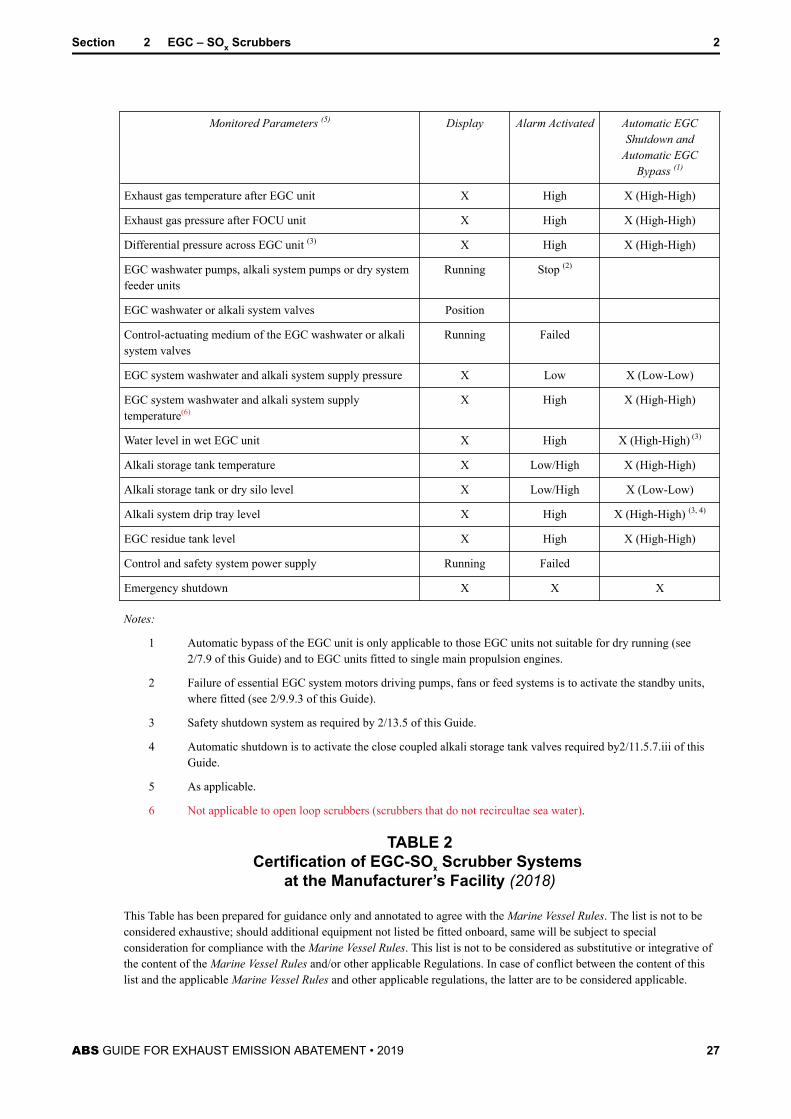
TABLE 1Monitoring and Safety System Functions for
EGC-SOx Scrubber Systems (1 April 2019)
Monitored Parameters (5) Display Alarm Activated Automatic EGCShutdown and
Automatic EGCBypass (1)
Exhaust fan motors Running Stop (2)
Exhaust bypass or isolation valves, where provided Position
Control-actuating medium of the exhaust bypass or isolationvalves
Running Failed
Exhaust gas temperature before EGC unit X High X (High-High)
Section 2 EGC – SOx Scrubbers 2
ABS GUIDE FOR EXHAUST EMISSION ABATEMENT • 2019 26
Monitored Parameters (5) Display Alarm Activated Automatic EGCShutdown and
Automatic EGCBypass (1)
Exhaust gas temperature after EGC unit X High X (High-High)
Exhaust gas pressure after FOCU unit X High X (High-High)
Differential pressure across EGC unit (3) X High X (High-High)
EGC washwater pumps, alkali system pumps or dry systemfeeder units
Running Stop (2)
EGC washwater or alkali system valves Position
Control-actuating medium of the EGC washwater or alkalisystem valves
Running Failed
EGC system washwater and alkali system supply pressure X Low X (Low-Low)
EGC system washwater and alkali system supplytemperature(6)
X High X (High-High)
Water level in wet EGC unit X High X (High-High) (3)
Alkali storage tank temperature X Low/High X (High-High)
Alkali storage tank or dry silo level X Low/High X (Low-Low)
Alkali system drip tray level X High X (High-High) (3, 4)
EGC residue tank level X High X (High-High)
Control and safety system power supply Running Failed
Emergency shutdown X X X
Notes:
1 Automatic bypass of the EGC unit is only applicable to those EGC units not suitable for dry running (see2/7.9 of this Guide) and to EGC units fitted to single main propulsion engines.
2 Failure of essential EGC system motors driving pumps, fans or feed systems is to activate the standby units,where fitted (see 2/9.9.3 of this Guide).
3 Safety shutdown system as required by 2/13.5 of this Guide.
4 Automatic shutdown is to activate the close coupled alkali storage tank valves required by2/11.5.7.iii of thisGuide.
5 As applicable.
6 Not applicable to open loop scrubbers (scrubbers that do not recircultae sea water).
TABLE 2Certification of EGC-SOx Scrubber Systems
at the Manufacturer’s Facility (2018)
This Table has been prepared for guidance only and annotated to agree with the Marine Vessel Rules. The list is not to beconsidered exhaustive; should additional equipment not listed be fitted onboard, same will be subject to specialconsideration for compliance with the Marine Vessel Rules. This list is not to be considered as substitutive or integrative ofthe content of the Marine Vessel Rules and/or other applicable Regulations. In case of conflict between the content of thislist and the applicable Marine Vessel Rules and other applicable regulations, the latter are to be considered applicable.
Section 2 EGC – SOx Scrubbers 2
ABS GUIDE FOR EXHAUST EMISSION ABATEMENT • 2019 27
Code Explanation
DR Design Review – Design review required.
MS Manufacture Survey – Product is to be surveyed during fabrication stages by the Surveyor.
FS Final Survey – Finished product is to be subject to final hydrostatic, nondestructive, operational testing, or anyother required tests, and witnessed by the Surveyor at manufacturer’s facility.
Equipment DR MS FS
EGC SOx scrubber reaction chamber X X X
Exhaust bypass or isolation valves X
Exhaust fans/motors (1) X X
Heat exchangers X X
Water treatment system X X
Washwater, alkali system and essential EGC system pumps (2) X X
Washwater, alkali and EGC residue associated piping X
Control and safety system X
Notes:
1 Applicable for motors over 100 kW (135 hp) only. For motors less than 100 kW (135 hp), certification by ABSnot required, acceptance based on manufacturer’s documentation and guarantee (see 2/9.9.1 of this Guide).
2 Applicable to pumps fitted to EGC systems connected to fuel oil combustion units rated at 2250 kW and aboveor internal combustion engines having cylinders of more than 300 mm (11.8 in.) bore [see 2/9.1.i of thisGuide].
Section 2 EGC – SOx Scrubbers 2
ABS GUIDE FOR EXHAUST EMISSION ABATEMENT • 2019 28
S E C T I O N 3 EGC – Selective Catalytic Reduction Systems
1 General (2018)This Section provides requirements on the arrangements and system design for exhaust emissionabatement systems primarily designed for the removal of NOx emissions using Selective CatalyticReduction (SCR) systems. The intent is that these requirements supplement the statutory emissionsperformance testing, survey, and certification requirements of the applicable IMO Regulations andGuidelines. At the time of issuance of this Guide, the applicable supplementary Guidelines to MARPOLAnnex VI Regulation 13 and the NOx Technical Code for SCR systems are IMO ResolutionMEPC.291(71) – 2017Guidelines Addressing Additional Aspects to the NOx Technical Code 2008 WithRegard to Particular Requirements Related to Marine Diesel Engines Fitted With Selective CatalyticReduction (SCR) Systems, adopted 7 July 2017. The statutory approval aspects would be made by ABS asa separate parallel process in the capacity of a Recognized Organization for the vast majority of flagAdministrations.
3 Plans and Data to be Submitted (2018)Plans and specifications covering the SCR arrangements are to be submitted and are, as applicable, toinclude:
● General arrangement of the SCR installation, layout, and systems
● Documentation detailing the SCR specification, including details of the SCR catalyst reaction chamberand catalysts, reductant specifications, exhaust system components/modifications, mixingarrangements, reductant injection nozzles/injectors, exhaust heaters and soot blowing details
● Analyses demonstrating compatibility of the SCR system with the engine (see 3/7.3 of this Guide)
● Hull plans showing the foundation and attachments to the vessel’s structure including scantlings,welding details, and foundation details of principal components
● Material specifications for the SCR unit, pumps, valves, reductant tanks, piping, distribution systems,filters, and associated components, including a corrosion assessment detailing the corrosive effect ofsystem liquids, vapors, and gases on the materials used in the exhaust emission abatement system
● Arrangement and capacity of reductant storage tanks
● Details of all piping systems, including details of piping and associated components, pumps, reductantdosing systems, air supply systems, design pressures, temperatures, insulation, and drip trays
● Descriptions and schematic diagrams for the control and monitoring systems, including set points forabnormal conditions and details of the location and position at which exhaust emission monitoringprobes are to be located
● Details of all electrical equipment installed for the SCR unit and associated systems, includingcomputer-based systems
● Failure Modes and Effects Analysis (FMEA) to determine possible failures and their effects in the safeoperation of the SCR exhaust emission abatement system [see 3/13.1 of this Guide]. Note: This can bea standalone document, or for those integrated SCR units, be incorporated in the engine FMEArequired by Appendix 4-2-1-A1 of the Marine Vessel Rules.
● Emergency shutdown arrangements
● SCR FMEA integration test report (see 3/15 of this Guide)
ABS GUIDE FOR EXHAUST EMISSION ABATEMENT • 2019 29
● Operating and maintenance instruction manuals, including MSDS sheets and details for handling ofhazardous and non-hazardous chemicals used in the SCR exhaust emission abatement system
● Testing procedures during installation and commissioning trials
5 SCR Operation and Maintenance Manuals (2018)In accordance with 1/11 of this Guide, detailed instruction manuals are to be provided onboard, coveringthe operations, safety, and maintenance requirements and occupational health hazards relevant to the SCRexhaust emission abatement equipment and associated systems.
These manuals are to include, but not necessarily be limited to, the procedures and schedules for operation,inspection, testing, and maintenance of the SCR and associated systems, the regular testing andmaintenance procedures for the monitoring systems, safety shutoff systems, and the integrity of backupsystems, together with special instructions for the use of vanadium based catalysts, bunkering, storage, anduse of hazardous or non-hazardous chemicals that may be used in the exhaust emission abatement systemand identification of the relevant responsible parties.
The manuals may be produced as standalone documents or incorporated within the general engineoperation and service manuals required by 4-2-1/1.9.3 of the Marine Vessel Rules.
The manuals are to be submitted for review solely to verify the presence of all the information required bythis Section.
7 SCR System Configuration and Vessel Integration
7.1 General (2018)i) SCR units are typically installed in the exhaust system of an internal combustion engine, if
applicable, before the exhaust gas economizer and as close as possible to the engine because of therelatively high exhaust gas temperatures required by the catalysts for effective NOx reductionreactions.
An SCR unit may be installed in place of the conventional exhaust silencer or in parallel with thesilencer when a bypass configuration is used. The exhaust systems from a number of engines maybe led to a common SCR unit (see 3/11.1.3 of this Guide).
For slow speed internal combustion engines with inherently low relative exhaust gas temperatures,this may necessitate the integration of the SCR reaction chamber and catalysts before theturbocharger exhaust turbine in a High Pressure SCR arrangement. The SCR catalysts may also beintegrated with the engine by close coupling to the engine, typically applicable to small high-speed internal combustion engines. In these cases, the SCR unit is considered a primary exhaustemission reduction technique that forms part of the total engine design and as such is to beintegrated by, or under authorization of, the engine designer. In those instances, the applicablerequirements for SCR systems contained within this Section of the Guide are supplementary to,and to be applied in association with, the requirements for internal combustion engines underSection 4-2-1 of the Marine Vessel Rules. The integration of an SCR system to an alreadyapproved internal combustion engine is not considered an engine type defining parameter changeas per 4-2-1/13.7.2 of the Rules.
It is to be noted that exhaust emission abatement systems that cause diesel engines to operateoutside the exhaust backpressure limits detailed in the approved IMO Annex VI Regulation 13Technical Files may invalidate the emissions certification and will require a re-approval of theengine NOx certification by the Administration or RO responsible for the original certification.
ii) SCR systems are to be designed to enable continued operation of the engine at the times the SCRsystem is not in operation, either through operational selection, equipment failure, or systemdeterioration through partial blocking/clogging.
Section 3 EGC – Selective Catalytic Reduction Systems 3
ABS GUIDE FOR EXHAUST EMISSION ABATEMENT • 2019 30
All SCR units fitted to single main propulsion engines are to be installed with an exhaust bypassarrangement unless arranged for unrestricted flow of exhaust gas and with no risk of causingfailure of the main propulsion engine.
iii) The response of the mechanical and electrical systems of the first SCR unit in a particular designseries is to be demonstrated by the FMEA integration test of 3/15 of this Guide.
7.3 Compatibility with the Engine (2018)i) Installation and operation of an exhaust emission abatement system is to be compatible with the
engine and not to cause any adverse effects on the engine performance such as excessive backpressures or high temperatures during operation.
ii) Details are to be submitted demonstrating the exhaust flow compatibility of the SCR unit with theconnected engine over the whole operational range of the engine. This data should demonstratethat the operating parameters of the engine do not exceed the approved design limits with the SCRsystem in operation. In the case of multi-engine SCR units, this compatibility evaluation is toshow that the SCR unit is capable of accommodating the maximum combined exhaust flows of allthe connected engines for the worst case scenario for that particular vessel arrangement andoperational profile. Consideration will be given to those SCR units that incorporate extractiveexhaust fans or air blowing systems to maintain the engine operating parameters within theapproved design limits.
It is to be noted that the normal and limit values for exhaust back pressure of engines fitted withSCR exhaust emission abatement systems, together with other regulatory aspects, are to bedetailed in the approved IMO Annex VI Regulation 13 Technical Files by the Administration orRO responsible for the NOx certification.
iii) The range of suitable fuels and oils for which the SCR unit is capable of continual operation, inparticular with respect to sulfur content or other elements known to cause catalyst clogging, is tobe declared by the SCR or engine manufacturer and included in the SCR or engine specificationdocumentation and instruction manuals required by 3/3 and 3/5 of this Guide.
Minimum and maximum exhaust gas temperatures, reductant flow rate limits, catalyst limitationsor health hazards, or other operating parameters that prohibit or limit SCR operation with theindicated range of suitable fuels and/or sulfur content are to be clearly defined in the manuals.
7.5 Redundancy (2018)Redundancy of equipment is to be provided for those rotating and reciprocating components that form partof the exhaust emission abatement unit essential supplementary systems, such as pumps, fans, blowers, etc.(see 3/9.1 and 3/9.11.3 of this Guide).
Consideration will be given to alternative means of compliance or operational measures to meet thisobjective on a case-by-case basis. As applicable, documentation is to be submitted demonstrating that thereliability of the system or component provides continued serviceability of the exhaust emission abatementsystem, without compromising the vessel propulsion and maneuvering capability. The provision ofsufficient spare parts onboard is an example of vessel specific arrangements that may be considered byABS as meeting this objective and should be justified with reference to the FMEA required by 3/13.1 ofthis Guide.
7.7 Essential ServicesFor the purposes of design, construction, testing, and survey, SCR units and associated components andsystems are considered secondary essential services in accordance with 4-8-1/7.3.3 of the Marine VesselRules.
Section 3 EGC – Selective Catalytic Reduction Systems 3
ABS GUIDE FOR EXHAUST EMISSION ABATEMENT • 2019 31
7.9 InclinationsExhaust emission abatement systems are to be designed for proper operation at the inclinationrequirements of 4-1-1/7.9 of the Marine Vessel Rules.
7.11 Inspection and Maintenance (2018)SCR systems are to be arranged for easy inspection and maintenance with at least one inspection port orhatch available for internal inspection of the main reaction chamber and where applicable the ability toreplace internal components is to be provided. Exemptions may be granted to those small SCR units notintended to be dismantled in service and typically integrated with high speed mass produced internalcombustion engines.
9 SCR System Equipment
9.1 Pumps/Fansi) Unless alternative means of compliance in accordance with 3/7.5 of this Guide are applicable,
redundant pumps, essential for the continual operation of the SCR system, are to be provided.There are to be at least two of these essential pumps, and the capacity of the pumps, with any onepump out of service, is to be sufficient for continuous operation of the exhaust emission abatementsystem at full rating. See also 3/9.11.3 of this Guide.
For vessels fitted with two or more identical exhaust emission abatement systems, the provision ofa common standby pump (for each essential system) capable of serving all SCR units will sufficerather than providing individual standby pumps for each SCR unit.
ii) Unless alternative means of compliance in accordance with 3/7.5 of this Guide are applicable andwhere exhaust fans form part of the SCR system and are essential for continual operation of theexhaust emission abatement system at full rating, such fans are to be installed in a redundantarrangement. The number and power of the fans should be such that if one fan, or a group of fans,is out of service the capacity of the remaining fan(s) is not to be less than 100% of the totalrequired.
9.3 Exhaust Heaters (2018)Where provided, burners and heat exchangers are to be designed, constructed, and certified in accordancewith Section 4-4-1 of the Marine Vessel Rules. Electrical heating systems are to meet the applicablerequirements of Part 4 Chapter 8 of the Marine Vessel Rules.
9.5 SCR Reductant System (2018)SCR technologies usually use an ammonia reductant introduced as an aqueous urea solution into theexhaust stream, prior to the catalyst blocks. For automotive and land-based engine applications, thisreductant solution is typically a 32.5% urea solution meeting the ISO 22241 standard (AUS 32). A specificmarine engine urea standard utilizing a 40% (AUS 40) urea solution has been developed by ISO (18611series).
The SCR manufacturer is to detail the specification of the reductant solution(s) appropriate for use with theSCR system and any specific installation considerations that may be applicable for storage, handling, anduse of the reductant. Urea is typically not classified as dangerous according to MSDS but can be an eye,skin, and respiratory irritant, and hence there is a need for the provision of appropriate safety features andpersonal protective equipment.
The key fluid media components of the SCR reductant system typically comprise reductant storage tank,pumps, filters, dosing units, and injectors with associated control systems. The specific requirements forSCR reductant system components using urea as a reductant are given under 3/11.3 of this Guide.
Section 3 EGC – Selective Catalytic Reduction Systems 3
ABS GUIDE FOR EXHAUST EMISSION ABATEMENT • 2019 32
Arrangements using alternative reductant solutions, such as aqueous ammonia or anhydrous ammonia, willbe considered on a case-by-case basis.
9.7 SCR Reaction Chamber (2018)i) Details of the SCR catalyst specifications, geometry, and fixing arrangements of the catalyst
elements in the reaction chamber are to be submitted.
ii) The catalyst elements are to be securely mounted in the reaction chamber to provide effective gassealing under all operational temperatures to provide effective reaction processes and prevent thepassage of unreacted ammonia to the atmosphere.
iii) Access arrangements for the catalyst elements are to provide easy removal and maintenance inservice. Sufficient space around the SCR reaction chamber for replacing the catalyst elements is tobe provided.
iv) Provision is to be made to indicate that catalyst elements have been removed from the reactionchamber so that reduction injection may be stopped. This may be achieved via the use of a deltapressure sensor, NOx efficiency monitor or other acceptable means.
v) Arrangements are to be provided to prevent the blocking or clogging of SCR catalyst elementswhich could create excessive exhaust backpressures for the connected engine, a reduction incatalyst reaction efficiency, and a fire hazard through soot accumulation. In general, this isexpected to be achieved by control system boundary conditions on reductant injection and by theinclusion of soot blowing arrangements for the catalyst chamber. Details of the soot blowingarrangements, where provided, are to be submitted for review.
The reductant injection strategies are to monitor exhaust temperatures to prevent catalystbreakdown and prevent reductant injection at those operating temperatures and modes that wouldcause excessive fouling of the catalyst elements by, for example, the formation of ammoniasulfates.
Arrangements are to be such that blocked catalyst elements will not prevent operation of theengine.
vi) Monitoring, alarm, and shutdown arrangements are to be provided to indicate:
a) An abnormal pressure rise across the SCR reaction chamber
b) Reductant injection rates above the conversion capability of the catalyst elements
c) Injection of reductant when the engine is not running or there is a fault with the catalystelements or the associated SCR reductant components or systems
9.9 Pneumatic Systemsi) Details of the pneumatic systems used for reductant injection, soot blowing, and any other
associated SCR systems are to be submitted. Pneumatic systems are to comply with therequirements of 4-6-7/5 of the Marine Vessel Rules.
ii) Air supply for these systems may be taken from existing vessel infrastructure provided it does notcompromise the air start supply and reserve requirements of 4-6-5/9 of the Marine Vessel Rules.
9.11 Electrical SystemThe electrical system and electrical equipment requirements in this Subsection are to be applied inassociation with the requirements of Part 4, Chapter 8 of the Marine Vessel Rules.
9.11.1 Electrical Motors and ControllersMotors and motor controllers of 100 kW (135 hp) and over are to be certified in accordance withPart 4, Chapter 8 of the Marine Vessel Rules.
Section 3 EGC – Selective Catalytic Reduction Systems 3
ABS GUIDE FOR EXHAUST EMISSION ABATEMENT • 2019 33
9.11.2 Electrical Load Analysis (2018)i) The number and capacity of generators are to be sufficient under normal seagoing
conditions with one generator in reserve to carry those loads for essential services and forminimum comfortable conditions of habitability as per 4-8-2/3.1.1 of the Rules.
ii) The electrical loads associated with the SCR system are to be included in the electric-plant load analysis required by 4-8-1/5.1.5 of the Marine Vessel Rules.
9.11.3 Standby Pump/Fan Arrangementsi) In the event of failure of the essential exhaust emission abatement system pumps or fans,
the standby pump or fan required by 3/9.1 of this Guide, where provided, is to beautomatically started and put into service. This failure is to be alarmed at the local andremote control station(s), as applicable.
ii) Where provided, each standby pump or fan is to be fed from separate sections of theswitchboard such that in the event of failure of one section of the switchboard the standbypump or fan may be fed from the other separate section of the switchboard.
9.11.4 Circuit Protection Devices and CompatibilityCircuit breakers are to be installed for miscellaneous SCR system electrical loads and are to becompatible with the prospective short circuit current level calculated at the switchboards.
11 SCR System Piping
11.1 Exhaust Gas Piping Systems11.1.1 Exhaust Gas Piping/Reaction Chamber Materials and Installation (2018)
i) Exhaust gas piping materials located before the reductant injection mixing sections orSCR reaction chamber may be of the same material specification as the standard exhaustgas piping.
ii) The sections of the SCR exhaust system and reaction chamber that are subjected toexhaust gas and reductant mixtures are to be constructed of suitable corrosion resistantmaterials.
Details of the exhaust mixers, mixing chambers, reductant nozzles, or injectors are to besubmitted. Injection arrangements are to be designed to provide effective mixing of thereductant and exhaust gas.
Non corrosion-resistant materials may be accepted downstream of the reductant andexhaust gas mixing area if it can be demonstrated that the required mixing of reductantand exhaust gas can reliably be achieved before the area of non-corrosion resistantmaterial under all normal operating conditions.
iii) The exhaust piping systems for exhaust emission abatement systems are to meet theapplicable requirements of 4-6-2/9 and 4-6-5/11 of the Marine Vessel Rules.
11.1.2 Exhaust Gas Piping Valvesi) Valves used in the exhaust system of emission abatement systems are to meet the
requirements of 4-6-2/5.11 of the Marine Vessel Rules and, in general, are to comply witha recognized standard and are to be permanently marked in accordance with therequirements of that standard.
ii) The valves are to be constructed of corrosion resistant materials.
iii) Isolation and bypass valves used in SCR system exhaust piping systems are to prevent thepassage of exhaust gases to other engines or machinery spaces.
Section 3 EGC – Selective Catalytic Reduction Systems 3
ABS GUIDE FOR EXHAUST EMISSION ABATEMENT • 2019 34
Where bypass arrangements for the SCR system are provided, the isolation and bypassvalves are to be arranged in an interlocked, fail safe manner, such that free flow ofexhaust gases to atmosphere at all times is possible, either through the SCR system orthrough the bypass. Bypass valves are to be provided with a local position indicator.
iv) Valves are to be installed in accessible locations, clear of or protected from obstructions,moving equipment, and hot surfaces, in order to permit regular inspection and/or periodicservicing.
11.1.3 Interconnections of Exhaust Gas Pipingi) Normally exhaust pipes from internal combustion engines are to be routed separately and
not interconnected. However, interconnected exhaust piping systems to a commonexhaust emission abatement unit may be accepted subject to the arrangements preventingthe passage or leakage of exhaust gases to other equipment or spaces that may then pose asafety risk to that equipment or health risk to the vessel’s crew or passengers. The returnof exhaust gas flow from a running engine to another stopped, or in operation, engine is tobe prevented.
ii) The combined SCR system is to be designed not to exceed the back pressure limitsspecified by the connected engines or boilers. Fans installed for this purpose are to meetthe redundancy requirements of 3/9.1.ii of this Guide.
11.1.4 Exhaust Gas Piping and SCR Reaction Chamber InsulationHot surfaces of exhaust emission abatement units or their associated equipment or systems likelyto come into contact with the crew during operation are to be suitably guarded or insulated. Wherethe surface temperatures are likely to exceed 220°C (428°F) and where any leakage, underpressure or otherwise, of fuel oil, lubricating oil, or other flammable liquid is likely to come intocontact with the SCR unit or exhaust pipes, these surfaces are to be suitably insulated with non-combustible materials that are impervious to such liquids. Insulation material not impervious to oilis to be encased in sheet metal cladding or an equivalent impervious sheath.
11.3 Reductant Piping Systems – Urea Solution (2018)The requirements for the reductant piping systems detailed in this Subsection are based on the use ofammonia as a reductant introduced in an aqueous urea solution at 32.5% or 40% concentrations.
11.3.1 Piping and Connectionsi) In general, pipe fittings and joints are to meet the requirements of the Marine Vessel Rules
for certification in 4-6-1/7.1, materials in 4-6-2/3, and design in 4-6-2/5.5 and 4-6-2/5.15,subject to the limitations in 4-6-5/7.3.3 TABLE 3.
ii) The reductant piping and venting systems are to be independent of other ship servicepiping and/or systems.
iii) Reductant piping systems are not to be located in accommodation, service, or controlspaces.
iv) Supply, bunkering, and transfer lines for reductant systems, with the exception of thoseassociated with injector equipment, are not to be located over boilers or in closeproximity to steam piping, exhaust systems, hot surfaces required to be insulated, or othersources of ignition.
v) The material of the reductant related piping systems, tanks, and other components whichmay come into contact with the reductant solution is to be of a suitable grade of non-combustible alloyed steel, plastic, or other compatible material established to be suitablefor the application.
Non-alloyed steels, copper, copper containing alloys, and zinc-coated steels are not to beused for reductant storage or piping systems.
Section 3 EGC – Selective Catalytic Reduction Systems 3
ABS GUIDE FOR EXHAUST EMISSION ABATEMENT • 2019 35
vi) Pipes and piping components made of thermoplastic or thermosetting plastic materials,with or without reinforcement, may be used in piping systems subject to compliance withthe requirements of Section 4-6-3 of the Marine Vessel Rules. For the purpose of theseRules, “plastic” means both thermoplastic and thermosetting plastic materials, with orwithout reinforcement, such as polyvinyl chloride (PVC) and fiber reinforced plastics(FRP). Plastic piping is to meet Level 3 fire endurance testing requirements (see4-6-3/5.11 of the Marine Vessel Rules).
vii) Flexible hoses are to comply with the requirements of 4-6-2/5.7 of the Marine VesselRules.
11.3.2 Filters and StrainersFilters are to be provided in reductant piping systems to minimize the entry of harmful foreignmaterial that may affect operation and closure of regulating valves, dosing valves, or otheressential system components. The filters are to be designed to withstand the maximum workingpressure of the system.
11.3.3 Arrangement of the Urea Storage Tank (2018)i) The urea storage tank is not to be situated where spillage or leakage from the tank
constitute a hazard by falling onto combustibles or heated surfaces and is to be located ina well-ventilated area away from heat sources.
The urea storage tank may be located within the engine room. If installed in a separatecompartment, the area is to be served by an effective mechanical supply and exhaustventilation system providing not less than 6 air changes per hour which is independentfrom the ventilation system of accommodation, service spaces, or control stations. Inaddition, if located in a separate compartment, the ventilation system is to be capable ofbeing controlled from outside the compartment and is to be maintained in operationcontinuously except when the storage tank is empty and has been thoroughly air purged.If the ventilation stops, an audible and visual alarm is to be provided outside thecompartment adjacent to each point of entry, and inside the compartment, together with awarning notice requiring the use of such ventilation.
Alternatively, where a urea storage tank is located within an engine room a separateventilation system is not required when the general ventilation system for the space isarranged so as to provide an effective movement of air in the vicinity of the storage tankand is to be maintained in operation continuously except when the storage tank is emptyand has been thoroughly air purged.
Where urea based ammonia solution is stored in integral tanks, the following are to beconsidered during the design and construction:
a) These tanks may be designed and constructed as an integral part of the hull, (e.g.,double bottom, wing tanks).
b) These tanks are to be coated with appropriate anti-corrosion coating and cannotbe located adjacent to any fuel oil and fresh water tank.
c) These tanks are to be fitted with but not limited to level gauge, temperaturegauge, high temperature alarm, low level alarm.
ii) The urea storage tank is to be protected from excessively high or low temperaturesapplicable to the particular urea concentration of the solution such as those specified inISO 18611 for AUS 40. Depending on the operational area of the vessel, this maynecessitate the fitting of heating and/or cooling systems. The physical conditionsrecommended by applicable recognized standards (such as ISO 18611-3) are to beconsidered to avoid any impairment of the urea solution during storage.
Section 3 EGC – Selective Catalytic Reduction Systems 3
ABS GUIDE FOR EXHAUST EMISSION ABATEMENT • 2019 36
iii) Every pipe emanating from a tank containing urea, which, if damaged, would allow ureato escape from the tank, is to be provided with a manual closing valve located directly onthe tank.
iv) The urea storage tank is to be provided with vent pipes complying with 4-6-4/9 of theMarine Vessel Rules and the outlets are to terminate in a safe location [see 4-6-4/9.3.5.ii.of the Marine Vessel Rules] in the weather and arranged to prevent entrance of water intothe urea tank.
The vents are not to be subject to deterioration due to the concentrations involved and thearrangement is to be such that the potential source of moisture from the vents does notpresent any danger to the crew or vessel. Alternatively, the tanks are to be fitted withappropriately sized pressure/vacuum valves.
v) The urea storage tank is to be provided with temperature and level monitoringarrangements. High and low level alarms together with high and low temperature alarmsare to be provided.
vi) Urea storage tanks are to be arranged so that they can be emptied of urea, purged andvented.
11.3.4 Spill TraysUrea storage tanks with a capacity of 500 liters (132 US gallons) and above are to be locatedwithin spill trays fitted with a high level alarm or arranged with a suitable drainage system.
11.3.5 Personnel Protection (2018)For the protection of crew members, the vessel is to have on board suitable protective equipmentconsisting of rubber gloves with long sleeves and tight-fitting chemical safety goggles or faceshields or both. The quantities of PPE carried onboard is to be appropriate for the number ofpersonnel engaged in regular handling operations or that may be exposed in the event of a failure;but in no case is there to be less than two sets available onboard.
Eyewash and safety showers are to be provided. The location and number of these eyewashstations and safety showers are to be derived from the detailed installation arrangements. As aminimum, the following stations are to be provided:
i) In the vicinity of transfer or treatment pump locations. If there are multiple transfer ortreatment pump locations on the same deck then one eyewash and safety shower stationmay be considered for acceptance provided that the station is easily accessible from allsuch pump locations on the same deck.
ii) An eyewash station and safety shower is to be provided in the vicinity of a chemicalbunkering station on-deck. If the bunkering connections are located on both port andstarboard sides, then consideration is to be given to providing two eyewash stations andsafety showers, one for each side.
iii) An eyewash station and safety shower is to be provided in the vicinity of any part of thesystem where the potential for a person to come into contact with the chemicals exists(e.g., openings such as filling/drainage or system connections/components that requireperiodic maintenance).
Depending on the specific arrangements (e.g., vessel type, size, layout of deck, machinery space,etc.), consideration may be given so that the personnel protection arrangements required by thissection may be shared with those required by 2/11.5.9 or 4/11.5.9 of this Guide.
Section 3 EGC – Selective Catalytic Reduction Systems 3
ABS GUIDE FOR EXHAUST EMISSION ABATEMENT • 2019 37
11.3.6 Safety Notices for the Compartment or at the Location of Tanks Containing UreaSafety instructions relating to precautions and corrective response actions are to be posted in thecompartment containing urea and beside the entrance to the compartment. Detailed guidelinesgiven in the MSDS are to be followed.
13 Control, Monitoring, and Safety Systems
13.1 Generali) The control system for the SCR exhaust emission abatement system may be connected to an
integrated control system or may be a standalone system. Where the SCR control system isintegrated in the base engine design, the control system is to be integrated with, or in directcommunication with, the engine control system.
ii) The system is to be designed such that a single fault of a component will not lead to a potentiallydangerous situation for human safety and/or the vessel.
An FMEA, or equivalent, demonstrating the safety system design basis is to be submitted.
iii) Where fitted, exhaust emissions monitoring systems are to meet the requirements of Section 5 ofthis Guide.
13.3 Control and Monitoring System (2018)i) Automatic control, alarm, and safety functions are to be provided for the SCR system so that
operations remain within preset parameters for all engine and exhaust emission abatement systemoperating conditions. For vessels with ACC or ACCU notations, the alarm and monitoringsystems are to be integrated in the vessel’s centralized monitoring systems that conform to therequirements for ACC or ACCU notations.
ii) The temperatures, pressures, and flows in the SCR system and associated systems are to becontrolled and monitored as follows:
a) A local control and monitoring system for the SCR system is to be provided to enableoperation, maintenance, and effective control in the event of an emergency or failure ofany remote controls. This may be integrated with the engine control system and/or be astandalone system.
b) The design of the control system is to provide identification of faults in the equipment, aswell as the process system. The control and monitoring systems are to comply with therequirements of 4-9-2/3.1 of the Marine Vessel Rules, as applicable.
c) Indications of parameters necessary for the safe and effective operation of the exhaustemission abatement process are to be provided at the local and, as applicable, remotecontrol station(s), as per 3/17.7 TABLE 1 of this Guide and are to include the followingparameters:
1) SCR system pump/fan/motor operational status
2) Status of any SCR system valves
3) SCR system parameters for operational safety
4) Level indication of SCR system tanks
5) Status of any SCR system alarms, shutdowns and Emergency Stop
d) Injection of reductant solutions outside the exhaust gas temperature limits specified by thecatalyst manufacturer is to be prohibited by the control system [see 3/9.7 of this Guide],and control strategies are to minimize ammonia slip and catalyst breakdown.
Section 3 EGC – Selective Catalytic Reduction Systems 3
ABS GUIDE FOR EXHAUST EMISSION ABATEMENT • 2019 38
e) The computer-based control systems are to comply with the applicable requirements of4-9-3 of the Marine Vessel Rules as a Category II system based on 4-8-3/15 of the MarineVessel Rules.
iii) The power supply arrangements for the control and monitoring system are to meet therequirements of 4-9-2/5.3 of the Marine Vessel Rules.
13.5 Safety Shutdown SystemA shutdown system is to be provided. This safety shutdown system is to be based on the followingprinciples:
i) Means are to be provided to indicate the parameters causing shutdown.
ii) Upon activation of the safety shutdown system, alarms are to be given at the normal controlposition and at the local control position.
iii) In the event where shutdown by the safety shutdown system is activated, the restart should notoccur automatically, unless after the system is reset.
Monitoring and safety shutdowns are to be in accordance with 3/17.7 TABLE 1 of this Guide.
15 FMEA Integration TestAn integration test is to be undertaken on the first SCR unit in a particular design series to verify that theoperation and response of the complete SCR mechanical and electrical systems are as predicted for alloperational modes. The scope of these tests is to be determined based on the FMEA required by 3/13.1 ofthis Guide.
17 Surveys During Construction
17.1 GeneralThis Subsection pertains to surveys during fabrication at the manufacturer’s facility and installation andtesting of SCR units onboard. As applicable, these surveys may be incorporated with the certification, shoptest, and shipboard tests required by the applicable aspects of 4-2-1/13 and 4-2-1/15 of the Marine VesselRules. For surveys at the manufacturer’s facility, the scope of the survey will be confined to only thoseitems that are supplied by the manufacturer.
17.3 Surveys at Manufacturer’s FacilitySee 3/17.7 TABLE 2 of this Guide for certification requirements of SCR units and associated systems.Survey requirements for equipment components and packaged units at the manufacturer’s facility aresummarized in the relevant sections of the applicable Rules/Guides.
17.5 Surveys During InstallationThe following surveys are to be carried out to the satisfaction of the attending Surveyor on the SCR unitand associated systems during installation and testing:
i) Inspection and verification that the foundations and attachments of the principal components ofthe SCR abatement unit and associated systems are in accordance with the approved plans andparticulars.
ii) Piping systems are to be visually examined and pressure-tested, as required by the Marine VesselRules. Pressure tests conducted on Class I piping systems (see 4-6-1/5 TABLE 1 of the MarineVessel Rules) should preferably be recorded on test charts for the duration of their tests.
iii) Electrical wiring and connections are to be in accordance with Part 4, Chapter 8 of the MarineVessel Rules and checked for continuity and proper workmanship.
iv) Instrumentation is to be tested to confirm proper operation as per its predetermined set points.
Section 3 EGC – Selective Catalytic Reduction Systems 3
ABS GUIDE FOR EXHAUST EMISSION ABATEMENT • 2019 39
v) Pressure relief and safety valves installed on the unit are to be tested.
vi) Control system and shutdowns are to be tested for proper operation.
vii) The SCR unit is to be checked for proper operation in accordance with the ABS approvedinstallation test procedure.
17.7 Surveys During TrialsDuring the initial commissioning trials, the SCR unit is to be confirmed for its satisfactory operation,including associated controls, alarms, and shutdowns. The tests are to be conducted in accordance with theABS-approved testing procedure during sea trials.
TABLE 1Monitoring and Safety System Functions for SCR Systems (2018)
Monitored Parameters Display AlarmActivated
Automatic SCRShutdown andAutomatic SCR
Bypass (1)
Exhaust fan motors Running Stop (2)
Ventilation fans Running Stop
Exhaust bypass or isolation valves, where provided Position
Control-actuating medium of the exhaust bypass or isolation valves, asapplicable
Running Failed
Exhaust gas temperature before SCR chamber X High X (High-High)
Exhaust gas temperature after SCR chamber X High X (High-High)
Differential pressure across SCR chamber X High X (High-High)
Reductant dosing pumps Running Stop (2)
Reductant system supply pressure X Low X (Low-Low)
Reductant storage tank temperature X Low/High X (High-High)
Reductant storage tank level X Low/High X (Low-Low)
Reductant tank drip tray level (3) High X (High-High)
Pneumatic supply pressure, injector and soot blowing systems X Low X (Low-Low)
Catalyst temperature or reductant injection out of boundary conditions(5) X Low/High X (High-High)
Control and safety system power supply Running Failed
Emergency shutdown X X X
Notes:
1 Automatic bypass of the SCR unit is applicable to those SCR units fitted with exhaust gas bypassarrangements [see 3/7.1.ii] of this Guide).
2 Failure of essential SCR system motors driving pumps or fans is to activate the standby units, where fitted (see3/9.11.3 of this Guide).
3 Urea storage tanks of 500 liters (132 US gallons) and above only (see 3/11.3.4 of this Guide).
4 As applicable.
5 See 3/9.7.vi of this Guide.
Section 3 EGC – Selective Catalytic Reduction Systems 3
ABS GUIDE FOR EXHAUST EMISSION ABATEMENT • 2019 40
TABLE 2Certification of SCR Systems at the Manufacturer’s Facility (2018)
This Table has been prepared for guidance only and annotated to agree with the Marine Vessel Rules. The list is not to beconsidered exhaustive; should additional equipment not listed be fitted onboard, same will be subject to specialconsideration for compliance with the Marine Vessel Rules. This list is not to be considered as substitutive or integrative ofthe content of the Marine Vessel Rules and/or other applicable Regulations. In case of conflict between the content of thislist and the applicable Marine Vessel Rules and other applicable regulations, the latter are to be considered applicable.
Code Explanation
DR Design Review – Design review required.
MS Manufacture Survey – Product is to be surveyed during fabrication stages by the Surveyor.
FS Final Survey – Finished product is to be subject to final hydrostatic, nondestructive, operational testing, or anyother required tests, and witnessed by the Surveyor at manufacturer’s facility.
Equipment DR MS FS
SCR unit X X X
Exhaust piping X
Exhaust bypass or isolation valves X
Exhaust fans/motors (1) X X
Heat exchangers, burners or heaters X X
Reductant system piping X
Pneumatic systems X
Control and safety system X
Notes:
1 Applicable for motors over 100 kW (135 hp) only. For motors less than 100 kW (135 hp), certification by ABSnot required, acceptance based on manufacturers documentation and guarantee (see 3/9.11.1 of this Guide).
Section 3 EGC – Selective Catalytic Reduction Systems 3
ABS GUIDE FOR EXHAUST EMISSION ABATEMENT • 2019 41
S E C T I O N 4 EGC – Exhaust Gas Recirculation Systems
1 General (2018)Exhaust Gas Recirculation systems fitted for the purposes of reducing internal combustion engine NOxemissions are considered primary exhaust emission reduction techniques forming part of the total enginedesign and as such are to be integrated by, or under authorization of, the engine designer. Those applicablerequirements for EGR systems contained within this Guide are supplementary to, and to be applied inassociation with, the requirements for internal combustion engines under 4-2-1 of the Marine Vessel Rules.
Those EGR systems that incorporate extensive off-engine systems that are designed for the purposes ofremoving the sulfur by-products from the exhaust gases that originate from the fuel and incorporate, forexample, water scrubbing and water cleaning systems, may be assigned the EGC-EGR notation uponrequest and in accordance with 1/9.7 of this Guide. The EGC-EGR notation is not intended to be appliedto those vessels that have installed engines that incorporate all EGR system components within the baseengine design and, for example, may be primarily designed for use with low sulfur fuels.
In all cases, the EGR system, or EGR version of the engine, is to be approved by incorporation to theexisting engine approval.
3 Plans and Data to be Submitted (2018)Plans and specifications covering the EGR arrangements are to be submitted and are, as applicable, toinclude:
● General arrangement of the EGR installation, layout, and systems
● Documentation detailing the EGR specification and associated water treatment systems, includingdetails of EGR specific components such as coolers, blowers, valves, etc.
● Hull plans showing the foundation and attachments of accessories to the vessel’s structure, includingscantlings, welding details, and foundation details of principal components
● Material specifications for the EGR equipment and associated systems, including coolers, blowers,pumps, valves, storage/process tanks, residue tanks, piping, distribution systems, separators, andassociated components, including a corrosion assessment detailing the corrosive effect of systemliquids, vapors, and gases on the materials used in the exhaust emission abatement system
● Arrangement and capacity of tanks for storage, chemicals, process washwater, exhaust gas cleaningresidues, etc.
● Details of all piping systems, including details of piping and associated components, design pressures,temperatures, insulation, and drip trays, where applicable
● Descriptions and schematic diagrams for the control and monitoring systems, including set points forabnormal conditions and details of the location and position at which exhaust emission or EGR ratemonitoring and washwater monitoring are to be located
● Details of all electrical equipment installed for the EGR unit and associated systems, includingcomputer-based systems
● Failure Modes and Effects Analysis (FMEA) to determine possible failures and their effects on theoperation of the EGR exhaust emission abatement system [see 4/13.1 of this Guide].Note: This can form a supplement or be incorporated in the engine FMEA required by Appendix 4-2-1-A1 of the
Marine Vessel Rules
ABS GUIDE FOR EXHAUST EMISSION ABATEMENT • 2019 42
● Emergency shutdown arrangements
● EGR FMEA integration test report (see 4/15 of this Guide)
● Operating and maintenance instruction manuals, including MSDS sheets and details for handling ofhazardous and non-hazardous chemicals used in the EGR exhaust emission abatement system
● Testing procedures during installation and commissioning trials
5 EGR Operation and Maintenance ManualsIn accordance with 1/11 of this Guide, detailed instruction manuals are to be provided onboard, coveringthe operations, safety, and maintenance requirements and occupational health hazards relevant to the EGRexhaust emission abatement equipment and associated systems.
These manuals are to include, but not necessarily be limited to, the procedures and schedules for operation,inspection, testing, and maintenance of the EGR system and associated systems, the regular testing andmaintenance procedures for the monitoring systems, safety shutoff systems, and the integrity of backupsystems, together with special instructions for the bunkering, storage, and use of hazardous and non-hazardous chemicals that may be used in the exhaust emission abatement system and identification of therelevant responsible parties.
The manuals may be produced as standalone documents or incorporated within the general engineoperation and service manuals required by 4-2-1/1.9.3 of the Marine Vessel Rules.
The manuals are to be submitted for review solely to verify the presence of all the information required bythis Section.
7 EGR System Configuration and Vessel Integration
7.1 General (2018)i) Exhaust Gas Recirculation is a NOx reduction technique where a portion of the exhaust gas,
typically up to 40%, is recirculated back into the engine which reduces the amount of excessoxygen within the cylinder and provides gases inert to combustion which act to absorb combustionheat and therefore reduce peak in-cylinder temperatures. This is considered a primary exhaustemission reduction technique and as such is to be integrated by, or under authorization of, theengine designer.
Furthermore, the relatively high sulfur content of marine fuels would typically necessitate the useof cleaning processes to be applied to the exhaust gases to avoid engine fouling and corrosionissues, similar to the water treatment systems applied to SOx scrubbers, and hence those aspects ofthe EGR system are to comply with the requirements of this Guide.
The integration of an EGR system to an already approved internal combustion engine is notconsidered an engine type defining parameter change as per 4-2-1/13.7.2 of the Rules.
ii) EGR systems are to be designed to enable continued operation of the engine at the times the EGRsystem is not in operation, either through operational selection, equipment failure, or systemdeterioration through partial blocking/clogging.
iii) The response of the mechanical and electrical systems of the first EGR unit in a particular designseries is to be demonstrated by the FMEA integration test of 4/15 of this Guide.
7.3 Compatibility with the Engine (2018)i) Installation and operation of the EGR system is to be compatible with the engine and not to cause
any adverse effects on the engine performance such as excessive back pressures or hightemperatures during operation.
Section 4 EGC – Exhaust Gas Recirculation Systems 4
ABS GUIDE FOR EXHAUST EMISSION ABATEMENT • 2019 43
ii) The range of suitable fuels for which the EGR system is capable of continual operation, inparticular with respect to sulfur content and other fuel elements known to cause fouling issues, isto be declared by the EGR manufacturer and included in the EGR specification documentation andinstruction manuals required by 4/3 and 4/5 of this Guide.
7.5 RedundancyRedundancy of equipment is to be provided for those rotating and reciprocating components that form partof the EGR essential supplementary systems, such as pumps, fans, blowers, etc. (see 4/9.1 and 4/9.7.3 ofthis Guide).
Consideration will be given to alternative means of compliance or operation to meet this objective on acase-by-case basis. As applicable, documentation is to be submitted demonstrating that the reliability ofthe system or component provides continued serviceability of the exhaust emission abatement system orthe alternative means of operation provides continued compliance with the statutory environmentalrequirements, without compromising the vessel propulsion and maneuvering capability. The provision ofsufficient spare parts onboard is an example of vessel specific arrangements that may be considered byABS as meeting this objective and should be justified with reference to the FMEA required by 4/13.1 ofthis Guide.
7.7 Essential ServicesFor the purposes of design, construction, testing, and survey, EGR units and associated components andsystems are considered secondary essential services in accordance with 4-8-1/7.3.3 of the Marine VesselRules.
7.9 Prevention of Floodingi) For EGR systems that incorporate a wet washwater scrubbing process, arrangements are to be
provided to prevent the ingress of scrubber washwater into the engine under any circumstance.
ii) Monitoring, alarm, and shutdown arrangements are to be provided to prevent an abnormal rise ofwashwater level in the EGR scrubber unit.
7.11 InclinationsExhaust emission abatement systems are to be designed for proper operation at the inclinationrequirements of 4-1-1/7.9 of the Marine Vessel Rules.
9 EGR System Equipment
9.1 Pumps/Blowersi) Where provided, pumps used in EGR SOx scrubber washwater, dosing, discharge, etc., systems,
essential for the continual operation of the EGR exhaust emission abatement system, are to betested and certified in accordance with 4-6-1/7.3 of the Marine Vessel Rules. This is applicable toexhaust emission abatement systems connected to internal combustion engines rated at 2250 kWand above or having cylinders of more than 300 mm (11.8 in.) bore.
ii) Unless alternative means of compliance in accordance with 4/7.5 of this Guide are applicable,redundant washwater, dosing, discharge, etc., pumps, essential for the continual operation of theEGR water systems, are to be provided. There are to be at least two of these essential pumps, thecapacity of the pumps, with any one pump out of service, is to be sufficient for continuousoperation of the exhaust emission abatement system at full rating. See also 4/9.7.3 of this Guide.
For vessels fitted with two or more identical EGR systems, the provision of a common standbypump (for each essential system) capable of serving all EGR units will suffice rather thanproviding individual standby pumps for each EGR unit.
Section 4 EGC – Exhaust Gas Recirculation Systems 4
ABS GUIDE FOR EXHAUST EMISSION ABATEMENT • 2019 44
iii) Unless alternative means of compliance in accordance with 4/7.5 of this Guide are applicable andwhere exhaust fans or blowers form part of the EGR system and are essential for continualoperation of the exhaust emission abatement system at full rating, such fans or blowers are to beinstalled in a redundant arrangement. The number and power of the fans or blowers should besuch that if one unit, or group of units, is out of service the capacity of the remaining units is notto be less than 100% of the total required.
iv) High-speed blowers of 100 kW (135 hp) and over are to be designed, constructed, and certified inaccordance with the applicable parts of Section 4-2-2 of the Marine Vessel Rules.
9.3 Heat Exchangers/EGR Exhaust Gas Coolersi) Where provided, heat exchangers are to be designed, constructed, and certified in accordance with
Section 4-4-1 of the Marine Vessel Rules.
ii) EGR exhaust gas coolers are not subject to 4/9.3.i of this Guide. Suitability of the cooler materialsfor the exhaust gases is to be demonstrated.
The coolers are to be hydrostatically tested on the water side to 4 bar (4.1 kgf/cm2, 57 psi), but notless than 1.5 times the design pressure on the water side, either in the manufacturer's plant or inthe presence of the Surveyor, after installation onboard the vessel. See also 4-2-1/13.3 of theMarine Vessel Rules for acceptance of manufacturer’s certificate.
9.5 Chemical Treatment SystemThe specific requirements for chemical treatment system components are given under 4/11.5 of this Guide.
9.7 Electrical SystemThe electrical system and electrical equipment requirements in this Subsection are to be applied inassociation with the requirements of Part 4, Chapter 8 of the Marine Vessel Rules.
9.7.1 Electrical Motors and ControllersMotors and motor controllers of 100 kW (135 hp) and over are to be certified in accordance withPart 4, Chapter 8 of the Marine Vessel Rules.
9.7.2 Electrical Load Analysis (2018)i) The number and capacity of generators are to be sufficient under normal seagoing
conditions with one generator in reserve to carry those loads for essential services and forminimum comfortable conditions of habitability as per 4-8-2/3.1.1 of the Rules.
ii) The electrical loads associated with the EGR system are to be included in the electric-plant load analysis required by 4-8-1/5.1.5 of the Marine Vessel Rules.
9.7.3 Standby Pump/Fan Arrangementsi) In the event of failure of the essential exhaust emission abatement system pumps or fans/
blowers, the standby pump or fan/blower required by 4/9.1 of this Guide, where provided,is to be automatically started and put into service. This failure is to be alarmed at the localand remote control station(s), as applicable.
ii) Where provided, each standby pump or fan/blower is to be fed from separate sections ofthe switchboard such that in the event of failure of one section of the switchboard thestandby pump or fan/blower may be fed from the other separate section of theswitchboard.
9.7.4 Circuit Protection Devices and CompatibilityCircuit breakers are to be installed for miscellaneous EGR system electrical loads and are to becompatible with the prospective short circuit current level calculated at the switchboards.
Section 4 EGC – Exhaust Gas Recirculation Systems 4
ABS GUIDE FOR EXHAUST EMISSION ABATEMENT • 2019 45
11 EGR System Piping
11.1 Exhaust Gas Piping Systems11.1.1 Exhaust Gas Piping/Scrubber Materials and Installation
i) Exhaust gas piping materials located before the EGR SOx scrubber, where fitted, may beof the same material specification as the standard engine exhaust gas piping.
ii) The sections of the scrubber that are subjected to washwater (e.g., the interior reactionchamber or washwater piping/nozzles, etc.) are to be constructed of suitable corrosionresistant materials.
iii) Exhaust gas piping materials used after the SOx scrubber unit are to be of a corrosionresistant material such as stainless steel.
11.1.2 Exhaust Gas Piping Valvesi) Valves used in the EGR exhaust system are to meet the requirements of 4-6-2/5.11 of the
Marine Vessel Rules and, in general, are to comply with a recognized standard and are tobe permanently marked in accordance with the requirements of that standard.
The valves are to be constructed of corrosion resistant materials.
ii) The EGR exhaust system valves are to be arranged for automatic position control andposition monitoring in association with the EGR control and monitoring system.
iii) Valves are to be installed in accessible locations, clear of or protected from obstructions,moving equipment, and hot surfaces, in order to permit regular inspection and/or periodicservicing.
11.1.3 EGR Scrubber and EGR System InsulationHot surfaces of EGR systems or their associated equipment or systems likely to come into contactwith the crew during operation are to be suitably guarded or insulated. Where the surfacetemperatures are likely to exceed 220°C (428°F) and where any leakage, under pressure orotherwise, of fuel oil, lubricating oil or other flammable liquid is likely to come into contact withthe EGR unit or exhaust pipes, these surfaces are to be suitably insulated with non-combustiblematerials that are impervious to such liquids. Insulation material not impervious to oil is to beencased in sheet metal cladding or an equivalent impervious sheath.
11.3 Washwater Piping11.3.1 Piping and Connections
i) Where applicable, the EGR SOx washwater system pipe fittings and joints are in generalto meet the requirements of the Marine Vessel Rules for certification in 4-6-1/7.1,materials in 4-6-2/3 and design in 4-6-2/5.5 and 4-6-2/5.15, subject to the limitations in4-6-5/7.3.3 TABLE 3.
Molded non-metallic expansion joints, where used, are to be of an approved type (see4-6-2/5.8.1, 4-6-2/9.19 TABLE 2 of the Marine Vessel Rules for Cu and Cu Alloy and4-6-2/9.19 TABLE 5A of the Marine Vessel Rules for pipe thickness).
ii) The piping material for the corrosive scrubber washwater system is to be selected basedon the corrosive nature of the liquid media.
iii) Pipes and piping components made of thermoplastic or thermosetting plastic materials,with or without reinforcement, may be used in piping systems subject to compliance withthe requirements of Section 4-6-3 of the Marine Vessel Rules. For the purpose of theseRules, “plastic” means both thermoplastic and thermosetting plastic materials, with orwithout reinforcement, such as polyvinyl chloride (PVC) and fiber reinforced plastics(FRP). Plastic washwater piping is to meet Level 3 fire endurance testing requirements(see 4-6-3/5.11 of the Marine Vessel Rules).
Section 4 EGC – Exhaust Gas Recirculation Systems 4
ABS GUIDE FOR EXHAUST EMISSION ABATEMENT • 2019 46
iv) Flexible hoses are to comply with the requirements of 4-6-2/5.7 of the Marine VesselRules.
11.3.2 Remote Control Valvesi) Upon loss of control power, the remote control valves are to remain in the last ordered
position, provided there is a readily accessible manual means to close the valves or are tofail safe in accordance with the FMEA.
ii) Remote control valves are to be clearly identified and are to be provided with positionindicators at the local and EGR system remote control station, as applicable.
iii) Valves are to be installed in accessible locations, clear of or protected from obstructions,moving equipment, and hot surfaces, in order to permit regular inspection and/or periodicservicing.
11.3.3 Overboard Dischargesi) Overboard discharges of any exhaust emission abatement system are not to be
interconnected to other systems.
ii) Special attention is to be paid to the corrosion resistivity of EGR washwater overboarddischarge piping. Where applicable, adequate arrangements are to be provided to preventgalvanic corrosion due to the use of dissimilar metals.
iii) Due consideration is to be given to the location of overboard discharges with respect tovessel propulsion features, such as thrusters, propellers or to prevent any discharge ofwater onto survival craft during abandonment. As applicable, discharges are to bearranged to enable safe sampling of water discharge plumes.
11.5 Chemical Treatment Piping SystemsThe requirements for the washwater chemical treatment system detailed in this Subsection are based on theuse of NaOH in the EGR scrubber water treatment system, as applicable. If other chemicals are to be used,the requirements should be consistent with the intent of the requirements for NaOH but would need to beassessed on a case-by-case basis.
The requirements detailed below are also based on an arrangement whereby the EGR residue tank is alsoused as an overflow tank for the NaOH storage tank. Arrangements that separate these functions intoseparate tanks may be applied, and in which case, the requirements for the overflow tank are detailed in4/11.5 of this Guide and the requirements for the residue tank in 4/11.7 of this Guide.
11.5.1 Material for Piping Systems, NaOH Storage Tank, and EGR Residue/NaOH Overflow TankThe material of the NaOH related piping systems, NaOH storage tank, EGR residue/NaOHoverflow tanks, drip trays, and any other components which may come into contact with theNaOH solution or sludge is to be of a suitable grade of stainless steel or other corrosion-resistantmaterial established to be suitable for the application. Aluminum, zinc, brass, or galvanized steelcomponents are not to be used.
11.5.2 Bunkering of NaOHi) The bunker station(s) for NaOH is to be located on the open deck away from sources of
ignition and arranged such that a spill at a bunker station would not result in NaOHcontacting or mixing with other incompatible materials.
Alternatively, closed or semi-enclosed bunker stations may be approved subject to theprovision of effective ventilation.
ii) Spill trays, which may be of the dry type or have means of drainage to the EGR residue/NaOH overflow tank, are to be provided.
Section 4 EGC – Exhaust Gas Recirculation Systems 4
ABS GUIDE FOR EXHAUST EMISSION ABATEMENT • 2019 47
11.5.3 Arrangement of the NaOH Storage Tank and the EGR Residue/NaOH Overflow Tanki) The NaOH storage and EGC residue/NaOH overflow tank are not to be situated where
spillage or leakage there from can constitute a hazard by falling onto combustibles orheated surfaces. In particular, these tanks are not to be located over boilers or in closeproximity to steam piping (supply or returns).
ii) Where necessary, the NaOH storage tank is to be provided with an appropriate heatingsystem to prevent freezing.
11.5.4 Filling, Vents, and Overflows for NaOH Tank and EGR Residue/NaOH Overflow Tank (2018)i) Filling.The NaOH storage tank is to be provided with a fill line from the bunker station
and a shut off valve is to be provided at the bunkering station.
Overflow and/or drains leading to the EGR residue/NaOH overflow tank are to enter at ornear the top of the tank. However, if this is determined to be impracticable, these lines areto be fitted with a non-return valve at the EGR residue/NaOH overflow tank.
ii) Vents.The NaOH storage and EGR residue/NaOH overflow tanks are to be provided withvent pipes complying with 4-6-4/9 of the Marine Vessel Rules, and the outlets are toterminate in a safe location [see 4-6-4/9.3.5.ii. of the Marine Vessel Rules] in the weather.
The vents are not to be subject to deterioration due to the concentrations involved, and thearrangement is to be such that the potential source of moisture from the vents does notpresent any danger to the crew or vessel. Alternatively, the tanks are to be fitted withappropriately sized pressure/vacuum valves.
iii) Overflow Protection.Means are to be provided to prevent NaOH from spilling oraccidently overflowing from the storage and EGR residue/NaOH overflow tanks.Accordingly, the NaOH storage tank is to be fitted with a high level alarm. Alternatively,the NaOH storage tank may be fitted with an overflow arrangement complying with4-6-4/13.5.4 and 4-6-4/9.5.2 of the Marine Vessel Rules that is led to the EGR residue/NaOH overflow tank. Further, in all cases, the EGR residue/NaOH overflow tank is to befitted with a high level alarm. Other anti-spilling arrangements may be considered on acase-by-case basis.
11.5.5 Sounding and Temperature Indication for the NaOH Storage and EGR Residue/NaOHOverflow Tanks
i) Sounding arrangements are to be provided for the NaOH storage and EGR residue/NaOHoverflow tanks, and are to comply with the sounding requirements applicable to fuel oiltanks of 4-6-4/11.3.7 of the Marine Vessel Rules.
ii) A sight glass is not to be used unless the materials of construction are compatible with theconcentration of NaOH solution involved, it is well protected from mechanical damage,and the arrangements are equivalent to that required in 4-6-4/11.3.7 of the Marine VesselRules, (i.e., flat “glass-type”), fitted with a self-closing valve at each end.
iii) In addition to local level gauging, the NaOH storage and EGR residue/NaOH overflowtanks are to have remote level gauging indication at the manned control station.
iv) The NaOH storage and EGR residue/NaOH overflow tank are to be provided with localand remote temperature monitoring arrangements. The remote temperature indication isto be installed at the manned control station.
11.5.6 Spill Traysi) Those areas of the NaOH storage and EGR residue/NaOH overflow tanks that could
result in leakage, locations where leakage from pumps and other associated equipmentsuch as strainers, heaters, flanges, valves, etc., which may require occasional dismantlingfor examination or maintenance may occur, and where leakage may otherwise normallybe expected are to be located within spill trays.
Section 4 EGC – Exhaust Gas Recirculation Systems 4
ABS GUIDE FOR EXHAUST EMISSION ABATEMENT • 2019 48
ii) Either drainage arrangements for the spill tray that lead to the dedicated EGR residue/NaOH overflow tank are to be provided or arrangements to activate an alarm in the eventof spillage are to be provided. Where drainage arrangements are provided, the drain lineto the EGR residue/NaOH overflow tank is to be fitted with a non-return valve.
11.5.7 Miscellaneous Piping Arrangements (2018)i) The NaOH piping systems are to be independent of other ship service piping and/or
systems.
ii) Piping systems for NaOH systems are not to be located in accommodation, service, orcontrol spaces.
iii) Every pipe emanating from a tank containing NaOH, which, if damaged, would allowNaOH to escape from the tank, is to be provided with a positive closing valve locateddirectly on the tank. The positive closing valve is to be provided with means of closureboth locally and from a readily accessible position outside of the space.
iv) Pipe joints are to be kept to a minimum. The direct connections of pipe lengths are to beall welded except for necessary flanged connections to valves and other equipment formaintenance in order to minimize risk of leakage from the pipe lines.
v) Supply, bunkering, and transfer lines for NaOH systems are not to be located over, or inclose proximity to, boilers, steam piping, exhaust systems, hot surfaces required to beinsulated, or other sources of ignition.
11.5.8 Ventilation ArrangementsThe NaOH storage and EGR residue/NaOH overflow tanks may be located within the engineroom or in a separate compartment. In either location, the area is to be served by an effectivemechanical exhaust ventilation system with ventilation inlets located where any vapors would beexpected to accumulate. In addition, if located in a separate compartment, the ventilation system isto be capable of being controlled from outside the compartment.
11.5.9 Personnel Protection (2018)For the protection of crew members, the vessel is to have on board suitable protective equipmentconsisting of large aprons, rubber gloves with long sleeves, rubber boots, coveralls of chemical-resistant material, and tight-fitting chemical safety goggles or face shields or both. The protectiveclothing and equipment is to cover all skin so that no part of the body is left unprotected. Thequantities of PPE carried onboard is to be appropriate for the number of personnel engaged inregular handling operations or that may be exposed in the event of a failure; but in no case is thereto be less than two sets available onboard.
Eyewash and safety showers are to be provided, the location and number of these eyewash stationsand safety showers are to be derived from the detailed installation arrangements. As a minimum,the following stations are to be provided:
i) In the vicinity of transfer or treatment pump locations. If there are multiple transfer ortreatment pump locations on the same deck then one eyewash and safety shower stationmay be considered for acceptance provided that the station is easily accessible from allsuch pump locations on the same deck.
ii) An eyewash station and safety shower is to be provided in the vicinity of a chemicalbunkering station on-deck. If the bunkering connections are located on both port andstarboard sides, then consideration is to be given to providing two eyewash stations andsafety showers, one for each side.
iii) An eyewash station and safety shower is to be provided in the vicinity of any part of thesystem where the potential for a person to come into contact with the chemicals exists(e.g., openings such as filling/drainage or system connections/components that requireperiodic maintenance).
Section 4 EGC – Exhaust Gas Recirculation Systems 4
ABS GUIDE FOR EXHAUST EMISSION ABATEMENT • 2019 49
Depending on the specific arrangements (e.g., vessel type, size, layout of deck, machinery space,etc.), consideration may be given so that the personnel protection arrangements required by thissection may be shared with those required by 2/11.5.9 or 3/11.3.5 of this Guide.
11.5.10 Safety Notices for the Compartment or at the Location of Tanks Containing NaOHSafety instructions relating to precautions and corrective response actions are to be posted in thecompartment containing NaOH and beside the entrance to the compartment. Detailed guidelinesgiven in the MSDS are to be followed.
11.7 Residue System (2018)i) The residues generated from the exhaust gas cleaning process are to be stored in a designated
residue tank, separate from the engine room sludge tank, and arranged for discharge to appropriateshore reception facilities in accordance with 4-6-4/5.7.4 of the Marine Vessel Rules.
The EGR residue tank is to be so designed as to facilitate cleaning.
Where EGR residue tanks used in closed loop chemical treatment systems are also used as theoverflow tank for the NaOH storage tank, the additional requirements of 4/11.5 of this Guide areto be applied.
ii) The material of the EGR residue tank is to be selected based on the corrosive nature of the EGRresidue.
iii) The capacity of the EGR residue tank is to be based on the expected residue volumes applicable tothe exhaust gas cleaning process and the maximum period of voyage between ports where EGRresidue can be discharged. In the absence of precise data, a figure of 30 days is to be used.
iv) The EGR residue tank is to be provided with vent pipes complying with 4-6-4/9 of the Rules.
v) The residue tank is to be arranged with a high level alarm.
vi) Sounding arrangements are to be provided for the EGR residue tank in accordance with4-6-4/11.3.7 of the Marine Vessels Rules.
vii) For those vessels that do not undertake onboard incineration and collect all engine room sludge fordisposal ashore, consideration will be given to arrangements utilizing a combined engine roomsludge and EGR residue tank, provided the tank meets the requirements of 4/11.7 of this Guide,EGR residue record logs satisfy the requirements of MEPC.259(68), and residues are disposed atMARPOL reception facilities.
Combined engine room sludge and EGR residue tanks are to be sized to provide adequate capacitybased on the sludge tank capacity requirements of 4-6-4/5.7.3 of the Marine Vessel Rulesplus thecapacity requirements for EGR residue tanks of 4/11.7.iii of this Guide.
13 Control, Alarm, and Monitoring System
13.1 Generali) The EGR control system is to be integrated with, or in direct communication with, the engine
control system. Control systems for associated systems, such as water treatment plants, may beconnected to an integrated control system or may be a standalone system.
ii) The system is to be designed such that a single fault of a component will not lead to a potentiallydangerous situation for human safety and/or the vessel.
An FMEA, or equivalent, demonstrating the safety system design basis is to be submitted.
iii) Where fitted, exhaust emissions monitoring systems are to meet the requirements of Section 5 ofthis Guide.
Section 4 EGC – Exhaust Gas Recirculation Systems 4
ABS GUIDE FOR EXHAUST EMISSION ABATEMENT • 2019 50
13.3 Control and Monitoring System (2018)i) Automatic control, monitoring (including washwater discharge criteria), alarm, and safety
functions are to be provided for the EGR system so that operations remain within presetparameters for all engine operating conditions. For vessels with ACC or ACCU notations, thealarm and monitoring systems are to be integrated in the vessel’s centralized monitoring systemsthat conform to the requirements for ACC or ACCU notations.
ii) The temperatures, pressures and flows in the EGR system and associated systems are to becontrolled and monitored as follows:
a) A local control and monitoring system for the EGR system is to be provided to enableoperation, maintenance, and effective control in the event of an emergency or failure ofany remote controls. This may be integrated with the engine control system and/or be astandalone system.
b) The design of the control system is to provide identification of faults in the equipment, aswell as the process system. The control and monitoring systems are to comply with therequirements of 4-9-2/3.1 of the Marine Vessel Rules, as applicable.
c) Indications of parameters necessary for the safe and effective operation of the exhaustemission abatement process are to be provided at the local and, as applicable, remotecontrol station(s), as per 4/17.7 TABLE 1 of this Guide and are to include the followingparameters:
1) EGR system pump/fan/blower/motor operational status
2) Status of any EGR system valves
3) EGR system parameters for operational safety
4) Level indication of EGR system tanks
5) Status of any EGR system alarms, shutdowns and Emergency Stop
d) The computer-based control systems are to comply with the applicable requirements ofSection 4-9-3 of the Marine Vessel Rules as a Category II system based on 4-8-3/15 of theMarine Vessel Rules.
iii) The power supply arrangements for the control and monitoring system are to meet therequirements of 4-9-2/5.3 of the Marine Vessel Rules.
13.5 Safety Shutdown System (2018)A shutdown system is to be provided. This safety shutdown system is to be based on the followingprinciples:
i) Means are to be provided to indicate the parameters causing shutdown.
ii) Upon activation of the safety shutdown system, alarms are to be given at the normal controlposition and at the local control position.
iii) In the event where shutdown by the safety shutdown system is activated, the restart should notoccur automatically, unless after the system is reset.
Monitoring and safety shutdowns are to be in accordance with 4/17.7 TABLE 1 of this Guide.
15 FMEA Integration TestAn integration test is to be undertaken on the first EGR unit in a particular design series to verify that theoperation and response of the complete EGR mechanical and electrical systems are as predicted for alloperational modes. The scope of these tests is to be determined based on the FMEA required by 4/13.1 ofthis Guide.
Section 4 EGC – Exhaust Gas Recirculation Systems 4
ABS GUIDE FOR EXHAUST EMISSION ABATEMENT • 2019 51
17 Surveys During Construction
17.1 GeneralThis Subsection pertains to surveys during fabrication at the manufacturer’s facility and installation andtesting of EGR equipment and associated systems onboard. These surveys may be incorporated with thecertification, shop test, and shipboard tests required by the applicable aspects of 4-2-1/13 and 4-2-1/15 ofthe Marine Vessel Rules. For surveys at the manufacturer’s facility, the scope of the survey will beconfined to only those items that are supplied by the manufacturer.
17.3 Surveys at Manufacturer’s FacilitySee 4/17.7 TABLE 2 of this Guide for certification requirements of EGR equipment and associatedsystems. Survey requirements for equipment components and packaged units at the manufacturer’s facilityare summarized in the relevant sections of the applicable Rules/Guides.
17.5 Surveys During InstallationThe following surveys are to be carried out to the satisfaction of the attending Surveyor on the EGRequipment and associated systems during installation and testing:
i) Inspection and verification that the foundations and attachments of the principal components ofthe EGR equipment and associated systems are in accordance with the approved plans andparticulars.
ii) Piping systems are to be visually examined and pressure-tested, as required by the Marine VesselRules. Pressure tests conducted on Class I piping (see 4-6-1/5 TABLE 1 of the Marine VesselRules) systems should preferably be recorded on test charts for the duration of their tests.
iii) Electrical wiring and connections are to be in accordance with Part 4, Chapter 8 of the MarineVessel Rules and checked for continuity and proper workmanship.
iv) Instrumentation is to be tested to confirm proper operation as per its predetermined set points.
v) Pressure relief and safety valves installed on the unit are to be tested.
vi) Control system and shutdowns are to be tested for proper operation.
vii) The EGR system is to be checked for proper operation in accordance with the ABS-approvedinstallation test procedure.
17.7 Surveys During TrialsDuring the initial commissioning trials, the EGR equipment and associated systems are to be confirmed fortheir satisfactory operation, including associated controls, alarms, and shutdowns. The tests are to beconducted in accordance with the ABS-approved testing procedure during sea trials.
TABLE 1Monitoring and Safety System Functions for EGR Systems (2018)
Monitored Parameters (4) Display AlarmActivated
Automatic EGRShutdown
EGR exhaust fan/blower motors Running Stop (1)
EGR exhaust bypass, isolation, mixing valves, where provided Position
Control-actuating medium of the EGR exhaust bypass, isolation or mixingvalves
Running Failed
Exhaust gas temperature before EGR unit X High X (High-High)
Exhaust gas temperature after EGR unit X High X (High-High)
Section 4 EGC – Exhaust Gas Recirculation Systems 4
ABS GUIDE FOR EXHAUST EMISSION ABATEMENT • 2019 52
Monitored Parameters (4) Display AlarmActivated
Automatic EGRShutdown
Engine air intake O2 concentration (or EGR rate) X Low/High X (Low-Low/High-High)
Differential pressure across EGR scrubber unit or EGR circuit, as applicable X High X (High-High) (2)
EGR washwater pumps, alkali system pumps Running Stop (1)
EGR washwater or alkali system valves Position
Control-actuating medium of the EGR washwater and alkali system valves,where provided
Running Failed
EGR washwater and alkali system supply pressure X Low X (Low-Low)
EGR washwater and alkali system supply temperature X High X (High-High)
Water level in EGR scrubber X High X (High-High)(2)
Alkali storage tank temperature X Low/High X (High-High)
Alkali storage tank level X Low/High X (Low-Low)
Alkali system drip tray level X High X (High-High) (3)
EGC residue tank level X High X (High-High)
Control and safety system power supply Running Failed
Emergency shutdown X X X
Notes:
1 Failure of essential EGR system motors driving pumps, fans or blowers is to activate the standby units, wherefitted (see 4/9.7.3 of this Guide).
2 Safety shutdown system as required by 4/13.5 of this Guide.
3 Automatic shutdown is to activate the close coupled alkali storage tank valves required by 4/11.5.7.iii of thisGuide.
4 As applicable.
TABLE 2Certification of EGR Equipment and Systems at the Manufacturer’s Facility
(2018)
This Table has been prepared for guidance only and annotated to agree with the Marine Vessel Rules. The list is not to beconsidered exhaustive; should additional equipment not listed be fitted onboard, same will be subject to specialconsideration for compliance with the Marine Vessel Rules. This list is not to be considered as substitutive or integrative ofthe content of the Marine Vessel Rules and/or other applicable Regulations. In case of conflict between the content of thislist and the applicable Marine Vessel Rules and other applicable regulations, the latter are to be considered applicable.
Code Explanation
DR Design Review – Design review required.
MS Manufacture Survey – Product is to be surveyed during fabrication stages by the Surveyor.
FS Final Survey – Finished product is to be subject to final hydrostatic, nondestructive, operational testing, or anyother required tests, and witnessed by the Surveyor at manufacturer’s facility.
Section 4 EGC – Exhaust Gas Recirculation Systems 4
ABS GUIDE FOR EXHAUST EMISSION ABATEMENT • 2019 53
Equipment DR MS FS
EGR SOx scrubber unit, as applicable X X X
Exhaust piping X
Exhaust bypass, isolation or mixing valves X
Exhaust fans/blowers (1, 2) X X
Heat exchangers (3) X X
Water treatment system X X
Washwater, alkali system and essential EGR system pumps (4) X X
Washwater, alkali and EGR residue associated piping X
Control and safety system X
Notes:
1 Applicable for motors over 100 kW (135 hp) only. For motors less than 100 kW (135 hp), certification by ABSnot required, acceptance based on manufacturer’s documentation and guarantee (see 4/9.7.1 of this Guide).
2 High-speed blowers of 100 kW (135 hp) and over are to be designed, constructed, and certified in accordancewith the applicable parts of Section 4-2-2 of the Marine Vessel Rules [see 4/9.1.iv of this Guide].
3 For EGR coolers, see 4/9.3 of this Guide.
4 Applicable to pumps fitted to EGR systems connected to internal combustion engines rated at 2250 kW andabove or having cylinders of more than 300 mm (11.8 in.) bore [see 4/9.1.i of this Guide].
Section 4 EGC – Exhaust Gas Recirculation Systems 4
ABS GUIDE FOR EXHAUST EMISSION ABATEMENT • 2019 54
S E C T I O N 5 Exhaust Emission Monitoring Systems
1 General (2018)The requirements in this Section provide guidance on the arrangements and system design for permanentlyinstalled Exhaust Emission Monitoring Systems (EEMS) designed for the monitoring of gaseous exhaustemission constituents, primarily for compliance verification of the NOx and SOx emissions. Thesemonitoring systems would, as a minimum, necessitate the measurement of the NOx, SO2, and CO2 gaseousspecies. Additional exhaust emission measurements for the purposes of fuel efficiency verification, orother gaseous species such as HC, CO, O2, or exhaust smoke/opacity/PM measurements, not specificallyrequired for compliance verification, may be considered on an optional and case-by-case basis.
The intent is that these requirements supplement the statutory specification, calibration, testing, and surveyrequirements of the applicable IMO Regulations and Guidelines. At the time of issuance of this Guide, theapplicable IMO requirements are detailed in the Revised MARPOL Annex VI and NOx Technical Code2008, IMO Resolution MEPC.291(71) – 2017 Guidelines Addressing Additional Aspects to the NOxTechnical Code 2008 With Regard to Particular Requirements Related to Marine Diesel Engines FittedWith Selective Catalytic Reduction (SCR) Systems, adopted 7 July 2017 and IMO ResolutionMEPC.259(68) – 2015 Guidelines for Exhaust Gas Cleaning Systems, adopted 15 May 2015. NOxemissions monitoring systems may be installed for the purpose of monitoring exhaust emission abatementsystems or for application as an alternative onboard NOx verification procedure in accordance with therequirements for Direct Measurement and Monitoring Systems of 6.4 and Appendix 8 of the NOxTechnical Code.
The statutory approval aspects would be made by ABS as a separate parallel process in the capacity of aRecognized Organization for the vast majority of flag Administrations.
3 Plans and Data to be SubmittedPlans and specifications covering the exhaust emission monitoring system arrangements are to besubmitted and are, as applicable, to include:
● General arrangement of the exhaust emission monitoring system installation, layout, and systems
● Documentation detailing the exhaust emission monitoring equipment and associated systemspecifications
● Details of the exhaust emission sampling and piping systems, including details of probes, pre-filters,heated lines, air supply arrangements, pure and calibration gas lines, design pressures, temperatures,materials, and insulation
● Descriptions and schematic diagrams for the control and monitoring systems, including set points forabnormal conditions and details of the location and position at which exhaust emissions monitoringprobes are to be located
● Details of all electrical equipment installed for the EEMS equipment and associated systems
● Schematic diagrams and operational descriptions of the exhaust emission monitoring equipment andassociated systems power supply arrangements
● Electrical one line diagrams depicting type, size, and protection of electrical cables used in the EEMScontrol and monitoring equipment
● Operating and maintenance instruction manuals
ABS GUIDE FOR EXHAUST EMISSION ABATEMENT • 2019 55
● Testing procedures during installation and commissioning trials
5 EEMS Operation and Maintenance ManualsIn accordance with 1/11 of this Guide, detailed instruction manuals are to be provided onboard, coveringthe operations, safety, and maintenance requirements and occupational health hazards relevant to theexhaust emission monitoring equipment and associated systems.
These manuals are to include, but not necessarily be limited to, the procedures and schedules for operation,inspection, testing, and maintenance of the EEMS together with identification of the relevant responsibleparties and special instructions for the health and safety implications of handling and proximity to exhaustgases and the storage and handling of pressurized bottles of pure and calibration gases. Special attention isto be paid to maintaining the continued serviceability and accuracy of the monitoring system.
The manuals are to be submitted for review solely to verify the presence of all the information required bythis Section.
7 Exhaust Emission Monitoring Systems
7.1 General (2018)i) Exhaust emissions monitoring systems may typically be installed for the purpose of, but not
limited to, verifying compliance with MARPOL Annex VI Regulations 13 and 14 for NOx or SOxgaseous emissions and may also be installed in association with an EGC aftertreatment system.
ii) Alternative emissions monitoring system design principles are permitted provided analyzerequivalency is demonstrated [see also 5/9.7.i of this Guide]. Accordingly, the requirements forcertain design features, such as sample handling and pneumatic systems detailed under 5/9.5 and5/9.11 of this Guide, respectively, may not be applicable to all exhaust emissions monitoringsystems.
iii) The notation for an exhaust emissions monitoring system may be assigned upon request to avessel fitted with, or without, an exhaust emission abatement system; see 1/9 of this Guide.
7.3 InclinationsExhaust emission monitoring systems are to be designed for proper operation at the inclinationrequirements of 4-1-1/7.9 of the Marine Vessel Rules.
9 EEMS Equipment
9.1 Generali) Due consideration is to be given to the safety implications related to the handling and proximity of
exhaust gases, the measurement equipment, and the storage and use of pressurized pure andcalibration gases. Such implications are to be documented in the operation and maintenancemanuals and suitable warning notices positioned at the sample points and measurementequipment.
ii) Where practicable, permanent access platforms are to be installed to enable safe operation andmaintenance of the exhaust emission monitoring equipment.
9.3 Sample Probes for Gaseous Emissions (2018)i) The gaseous sampling probes are to be positioned to enable sampling of a representative exhaust
gas sample after the engine, turbocharger, or EGC system, in accordance with the location andtemperature criteria of 5.9.3.1 and 5.9.3.2 of the NOx Technical Code.
Sample probes are to meet the design requirements of 1.2.1 of Appendix 3 of the NOx TechnicalCode.
Section 5 Exhaust Emission Monitoring Systems 5
ABS GUIDE FOR EXHAUST EMISSION ABATEMENT • 2019 56
ii) A sample probe connection flange designed in accordance with Section 5 of Appendix 8 of theNOx Technical Code and 5/9.3 of this Guide is to be provided for each engine required to bemonitored.
iii) The sample probe connection flanges are preferably to be installed in accessible locations, clear ofor protected from obstructions or moving equipment, in order to permit regular inspection and/orperiodic servicing.
iv) In order to establish the capability of the sample probe to withstand fatigue, which is likely tooccur due to vibrations under operating conditions, each sample probe design is to be vibrationtested in accordance with a recognized standard, such as IEC 60068-2-6 for location on engines,as per 4-9-9/15.7 TABLE 1, Item 5, to 10g of the Marine Vessel Rules.
9.5 Sample Handlingi) Where applicable, pre-filters and heated sample lines are preferably to be installed in accessible
locations, clear of or protected from obstructions or moving equipment, in order to permit regularinspection and/or periodic servicing.
Pre-filters and heated lines are to meet the design requirements of 1.2.2-5 of Appendix 3 of theNOx Technical Code.
ii) In order to establish the capability of the pre-filters and sample lines to withstand fatigue, which islikely to occur due to vibrations under operating conditions, each design is to be vibration tested inaccordance with a recognized standard, such as IEC 60068-2-6, as per 4-9-9/15.7 TABLE 1, Item5, to 4g of the Marine Vessel Rules.
iii) Hot surfaces of pre-filters or heated lines likely to come into contact with the crew duringoperation are to be suitably guarded or insulated. Where the surface temperatures are likely toexceed 220°C (428°F) and where any leakage, under pressure or otherwise, of fuel oil, lubricatingoil or other flammable liquid is likely to come into contact with the sampling components orexhaust pipes, these surfaces are to be suitably insulated with non-combustible materials that areimpervious to such liquids. Insulation material not impervious to oil is to be encased in sheetmetal cladding or an equivalent impervious sheath.
9.7 Analyzer Specifications and Calibrationi) The EEMS gaseous analyzers are to be in accordance with the principles and specifications of
Appendix 3 of the NOx Technical Code or else demonstrated as equivalent in accordance with ISO5725-1 and 5725-2, as permitted by 5.4.2 of the NOx Technical Code and ISO 8178-1 Section 7, tothe satisfaction of ABS.
ii) Calibration of the EEMS analyzers is to be in accordance with Appendix 4 of the NOx TechnicalCode or else demonstrated as equivalent to the satisfaction of ABS.
9.9 Data Recording and Processing Devicei) The EEMS is to be capable of recording calibration and emissions monitoring data. This
capability may be incorporated within the EEMS control or integrated system.
ii) The data recording device should be capable of preparing data and reports over specified timeperiods in a readily readable format capable of being downloaded and printed by an attendingSurveyor.
9.11 Pneumatic Systemsi) Where applicable, details of the pneumatic arrangements used for exhaust emission monitoring
systems are to be submitted and are to comply with the requirements of 4-9-2/5.7 of the MarineVessel Rules.
ii) Air supply for these systems may be taken from existing vessel infrastructure provided it does notcompromise the air start supply and reserve requirements of 4-6-5/9 of the Marine Vessel Rules.
Section 5 Exhaust Emission Monitoring Systems 5
ABS GUIDE FOR EXHAUST EMISSION ABATEMENT • 2019 57
11 Monitoring System
11.1 GeneralThe control system for the exhaust emission monitoring system may be connected to an integrated controlsystem or may be a standalone system.
11.3 Monitoring Systemi) The design of the monitoring system is to provide identification of faults in the equipment, as well
as the process system.
ii) The system is to be of a self-monitoring type, and means of testing the alarms are to be provided.
iii) The computer-based monitoring systems are to comply with the applicable requirements ofSection 4-9-3 of the Marine Vessel Rules as a Category II system based on 4-8-3/15 of the MarineVessel Rules.
iv) The electronic control equipment is to be performance tested in the presence of the Surveyor or bya recognized testing laboratory, in accordance with the criteria of 4-9-9/15.7 TABLE 1 and4-9-9/15.7 TABLE 2of the Marine Vessel Rules.
v) The power supply arrangements for the monitoring system are to meet the requirements of4-9-2/5.3 of the Marine Vessel Rules.
Monitoring is to be in accordance with 5/13.5 TABLE 1 of this Guide.
13 Surveys During Construction
13.1 GeneralThis Subsection pertains to surveys during installation and testing of EEMS units onboard.
13.3 Surveys During InstallationThe following surveys are to be carried out to the satisfaction of the attending Surveyor on the EEMS unitand associated systems during installation and testing:
i) Piping systems are to be visually examined and pressure-tested, as required by the Marine VesselRules. Pressure tests conducted on Class I piping systems (see 4-6-1/5 TABLE 1 of the MarineVessel Rules) should preferably be recorded on test charts for the duration of their tests.
ii) Electrical wiring and connections are to be in accordance with Part 4, Chapter 8 of the MarineVessel Rules and checked for continuity and proper workmanship.
iii) Instrumentation is to be tested to confirm proper operation as per its predetermined set points.
iv) Pressure relief and safety valves installed on the unit are to be tested.
v) Control system and alarms are to be tested for proper operation.
vi) The EEMS unit is to be checked for proper operation in accordance with the ABS approvedinstallation test procedure.
13.5 Surveys During TrialsDuring the initial commissioning trials, the EEMS is to be confirmed for its satisfactory operation,including associated controls, alarms, and shutdowns. The tests are to be conducted in accordance with theABS-approved testing procedure during sea trials.
Section 5 Exhaust Emission Monitoring Systems 5
ABS GUIDE FOR EXHAUST EMISSION ABATEMENT • 2019 58
TABLE 1Monitoring System Functions for EEMS Systems (2018)
Monitored Parameters (1) Display Alarm Activated
Analyzer/EEMS power supply X Failed
Pneumatic air supply, as applicable Failed
Exhaust gas sample temperature X Low/High
Pre-filter and heated line temperature, as applicable X Low/High
Sampling flow rate, as applicable X Low
Data logging X Failed
Note:
1 As applicable.
Section 5 Exhaust Emission Monitoring Systems 5
ABS GUIDE FOR EXHAUST EMISSION ABATEMENT • 2019 59
S E C T I O N 6 Surveys After Construction and Maintenance ofClass
1 GeneralThis Section pertains to periodical surveys after construction for the equipment described in Sections 1 to 5of this Guide.
1.1 DefinitionsFor definitions related to the surveys of equipment covered by this Guide, see Section 1 of this Guide and7-1-1/3 of the ABS Rules for Survey After Construction (Part 7).
1.3 ModificationsWhen it is intended to carry out any modifications to the exhaust emission abatement system, associatedcomponents, or monitoring equipment, which may affect classification, including substitutions of materialdiffering from that originally installed, the details of such modifications are to be submitted for review. IfABS determines that the modification will affect classification, the affected system or component to bemodified will be subject to the review, testing, and survey requirements in accordance with this Guide.
3 Survey Intervals
3.1 Annual Survey (2018)An Annual Survey of a vessel fitted with exhaust emission abatement equipment, monitoring equipment,and installed classed systems covered by 1/9 of this Guide is to be carried out within three (3) monthsbefore or after each annual anniversary date of the crediting of the previous Special Periodical Survey ororiginal construction date. For vessels on Continuous Survey, all Continuous Survey requirements forthose parts (items) due are generally to be completed each year. The Annual Survey will not be creditedand the Certificate of Classification will not be endorsed unless Continuous Survey items that are due oroverdue at the time of the Annual Survey are either completed or granted an extension.
3.3 Special Periodical Survey (2018)A Special Periodical Survey of exhaust emission abatement equipment, associated systems, andmonitoring equipment covered by 1/9 of this Guide is to be completed within five years after the date ofconstruction or after the crediting date of the previous Special Periodical Survey. The fifth Annual Surveymust be credited as a requirement of the Special Periodical Survey. The interval between Special PeriodicalSurveys may be reduced by the Committee.
The Special Periodical Survey may be commenced at the fourth Annual Survey and be continued withcompletion by the fifth anniversary date. Where the Special Periodical Survey is commenced prior to thefourth Annual Survey, the entire survey is to be completed within fifteen (15) months if such work is to becredited to the Special Periodical Survey.
A Special Periodical Survey will be credited as of the completion date of the survey but not later than fiveyears from date of construction or from the date recorded for the previous Special Periodical Survey. If theSpecial Periodical Survey is completed within three (3) months prior to the due date, the Special PeriodicalSurvey will be credited to agree with the effective due date. Special consideration may be given to Special
ABS GUIDE FOR EXHAUST EMISSION ABATEMENT • 2019 60
Periodical Survey requirements in unusual cases. Consideration may be given for extensions of Rule-required Special Periodical Surveys under exceptional circumstances.
3.5 Continuous Survey ProgramAt the request of the Owner, and upon approval of the proposed arrangements, a system of ContinuousSurveys may be undertaken, whereby the Special Periodical Survey requirements are carried out in regularrotation to complete all of the requirements of the particular Special Periodical Survey within a five-yearperiod. The proposed arrangements are to provide for survey of approximately 20% of the total number ofsurvey items during each year of the five-year period. Reasonable alternate arrangements may beconsidered as recommended by the manufacturer.
Generally, each part (item) surveyed becomes due again for survey approximately five (5) years from thedate of the survey, and the due parts (items) are generally to be completed each year. For ContinuousSurveys, a suitable notation will be entered in the Record and the date of the completion of the cyclepublished.
ABS may withdraw its approval for Continuous Survey if the Surveyor’s recommendations are notcomplied with.
3.7 Survey Based upon Preventative Maintenance TechniquesA properly conducted approved program of preventative-maintenance/condition-monitoring plan may becredited as satisfying the requirements of Special Continuous Survey. This plan must be in accordancewith Appendix 7-A1-14 “Surveys Based on Preventative Maintenance Techniques” of the ABS Rules forSurvey After Construction (Part 7).
5 Surveys
5.1 Annual Surveys5.1.1 General (2018)
The following should be carried out during each Annual Survey of the exhaust emissionabatement equipment, associated systems, and monitoring equipment covered by 1/9 of this Guideunless all the requirements of 6/7 of this Guide are complied with:
i) General. The logbooks are to be examined with regard to correct functioning of theexhaust emission abatement systems, emissions monitoring, and washwater monitoringsystems, etc. The hours per day of the prime movers, EGC SOx scrubbers, SCR systems,EGR systems, exhaust emission monitoring systems, as applicable, are to be consideredtogether with historical records.
ii) Operating and Maintenance Instruction Manual. The approved instructions and manualscovering the operations, safety, and maintenance requirements and occupational healthhazards relevant to exhaust emission abatement units and associated systems are to beconfirmed as being aboard the vessel.
iii) Instrumentation, Control, Monitoring, and Safety Systems. The instrumentation, control,monitoring, and safety equipment applicable to each particular type of installed exhaustemission abatement unit and associated systems, including indicators and alarms, is to beconfirmed in satisfactory operating conditions. The examination is to be made with one ormore ship’s service generator(s) in operation and the control system energized to permitrandom checking of function indicators, alarms, and such control actuators as may beoperational. Installed interlocks, where applicable, are to be verified in workingcondition.
iv) Exhaust Gas Handling Piping and Machinery. All piping, hoses, bellows, blowers/fans,heaters, dry scrubbing equipment, soot blowing equipment, emergency shutdown or
Section 6 Surveys After Construction and Maintenance of Class 6
ABS GUIDE FOR EXHAUST EMISSION ABATEMENT • 2019 61
bypass valves, remote operating valves, and machinery and equipment associated withprocessing or distribution of exhaust gases is to be examined, as far as possible. Stoppingof pumps, fans, and blowers upon emergency shutdown of the system is to be confirmed.
Where applicable, exhaust system bypass, isolation, or mixing valve sealing arrangementsare to be examined.
The integrity and effectiveness of insulation arrangements is to be confirmed.
v) Water Treatment, Reductant, and Residue Systems. All tanks, piping, hoses, pumps,strainers, separators, filtration units, dosing systems, and equipment associated withprocessing of washwater, injection of reductant or collection of exhaust residues are to beexamined and verified to be in operational condition.
vi) Drip Trays, Overflow Arrangements, and Insulation. Drip trays, overflow arrangements,shielding, or insulation installed for the protection of personnel or the vessel from theeffects of hazardous or corrosive chemicals used in exhaust emission abatement systemsor system temperatures are to be examined for continued suitability for their intendedservice.
vii) Electrical Equipment. Electrical equipment associated with the operation or monitoring ofexhaust emission abatement systems is to be examined for continued suitability for itsintended service and installation area.
viii) Personal Protective Equipment. The required PPE equipment and facilities are to beconfirmed as being onboard and in an operational condition.
ix) Warning Notices. The location of the applicable warning notices is to be confirmed.
x) Spare Parts. Spare parts are to be verified as available onboard in consideration of theequipment redundancy arrangements.
5.1.2 EGC – SOx ScrubbersThe following are to be examined, so far as applicable, during each Annual Survey. Insulationneed not be removed, but any deterioration or evidence of leakage is to be investigated:
i) External Examination. External examination of all components including scrubber units,piping, tanks, fans, insulation, valves, pumps, drip trays, etc., including foundations andattachments.
ii) Equipment Operation. Confirmation of correct operation of all rotating and reciprocatingcomponents, such as exhaust gas fans, water treatment pumps, dry handling conveyors,ventilation fans, etc.
iii) Control Valves. Verify the correct operation of all remotely operated or automaticallycontrolled valves in the exhaust, water treatment, or dry handling systems.
iv) System Operation. Examination of the exhaust emission abatement system duringworking condition. Multi-mode SOx scrubbers are to be tested in all operational modes asfar as practicable.
5.1.3 EGC – SCR Systems (2018)The following are to be examined, so far as applicable, during each Annual Survey. Insulationneed not be removed, but any deterioration or evidence of leakage is to be investigated:
i) External Examination. External examination of all components, including SCR reactionchamber, injectors, dosing units, heating, soot blowing equipment, piping, tanks,insulation, valves, pumps, drip trays, etc., including foundations and attachments.
ii) Equipment Operation. Confirmation of correct operation of all rotating and reciprocatingcomponents, such as dosing pumps, ventilation fans, etc.
Section 6 Surveys After Construction and Maintenance of Class 6
ABS GUIDE FOR EXHAUST EMISSION ABATEMENT • 2019 62
iii) Control Valves. Verify the correct operation of all remotely operated or automaticallycontrolled valves in the exhaust, reductant dosing, or soot blowing systems.
iv) System Operation. Examination of the exhaust emission abatement system duringworking condition.
5.1.4 EGC – EGR SystemsThe following are to be examined, so far as applicable, during each Annual Survey. Insulationneed not be removed, but any deterioration or evidence of leakage is to be investigated:
i) External Examination. External examination of all components including scrubbers, EGRcoolers, piping, tanks, blowers, insulation, valves, pumps, drip trays, etc., includingfoundations and attachments.
ii) Equipment Operation. Confirmation of correct operation of all rotating and reciprocatingcomponents such as exhaust gas blowers, water treatment pumps, ventilation fans, etc.
iii) Control Valves. Verify the correct operation of all remotely operated or automaticallycontrolled valves in the exhaust or water treatment systems.
iv) System Operation. Examination of the exhaust emission abatement system duringworking condition at full EGR rate. Multi-mode systems are to be tested in all operationalmodes as far as practicable.
5.1.5 Exhaust Emissions Monitoring SystemsThe following are to be examined, so far as applicable, during each Annual Survey. Insulationneed not be removed, but any deterioration or evidence of leakage is to be investigated:
i) External Examination. External examination of all components including exhaust gassample probes, pre-filters, heated lines, analyzer units, pneumatic systems, span andcalibration gases, etc.
ii) System Operation. Examination of the EEMS during calibration and exhaust gas samplingconditions; verification of the emissions monitoring and data logging functions is to beundertaken.
5.3 Special Periodical Survey (2018)In addition to the items covered by the Annual Survey listed in 6/5.1 of this Guide, the Special Survey ofthe exhaust emission abatement equipment, associated systems, and monitoring equipment covered by 1/9of this Guide is also to include the following:
i) Washwater, Water Treatment, and Dosing Pumps. All washwater, water treatment pumps, andreductant dosing pumps are to be examined including opening for examination, as deemednecessary.
ii) Exhaust Fans and Blowers. All exhaust fans, EGR blowers and associated prime movers are to beexamined including opening for examination, as deemed necessary.
iii) Control Valves. All bypass, mixing, isolating, shut-down, or control valves in the exhaust, watertreatment, and dosing systems are to be inspected and proven operable. Pressure relief valves areto be function-tested. A random selection of valves is to be opened for examination and adjustedas necessary.
iv) Control Actuators. All mechanical, hydraulic, and pneumatic control actuators and their powersystems are to be examined and tested as considered necessary.
v) Electrical Equipment. The electrical equipment is to be examined to include the physical conditionof electrical cables and supports, together with insulation resistance testing of the windings ofelectrical control motors and actuators. Where a proper record of testing is maintained,consideration may be given to accepting recent readings.
Section 6 Surveys After Construction and Maintenance of Class 6
ABS GUIDE FOR EXHAUST EMISSION ABATEMENT • 2019 63
vi) Automatic Controls. Automatic controls for components associated with the exhaust emissionabatement equipment and associated systems, including auto-changeover for system pumps/fansand electrical power supply, are to be examined for functionality and for continued systemserviceability.
vii) Instrumentation, Control, Monitoring, and Safety Systems. Control systems are to be subjected todock trials to verify correct operation of the following automatic functions, alarms, and safetysystems:
● Function test of the monitoring and alarm systems
● Function test of safety systems, including override of system functions, if provided
● Manual control of the EGC equipment and systems
● Automatic changeover of designated machinery associated with the exhaust emissionabatement equipment.
7 Alternative SurveysABS is at all times ready to consider alternative survey arrangements which can be shown, through eithersatisfactory service experience or a systematic analysis based on sound engineering principles, to meet theoverall safety, serviceability, and standards of the Marine Vessel Rules and this Guide. Alternative torequirements particularly contained in 6/5 of this Guide, an In-Service Inspection Plan (ISIP) may bedeveloped by the Owner and submitted to the Assistant Chief Surveyor’s office for review. A stampedcopy of the ISIP placed onboard the vessel is to be referenced during all of the scheduled surveys.
Section 6 Surveys After Construction and Maintenance of Class 6
ABS GUIDE FOR EXHAUST EMISSION ABATEMENT • 2019 64