Exhibit 2 Technical Criteria Transfer Pumps 1.0 INTRODUCTION 1.1 General Overview Components of the work consist of, but are not limited to, the following: a) Review all existing as-built drawings and confirm on site dimensions of pipelines, pressure ratings of pipes and fittings, grades, top and bottom water levels, suction regimes and duty points of existing pumps, which will include step testing of the existing pumps, (and report on any underperforming pumps), b) Review and confirm the capacity of the existing electrical supply, including all conduits, cables, transformers, switchgear, motor control centers, space availability and the ability to accommodate the proposed larger pumps and related electrical equipment, c) Design and select two new pumps to run in parallel with the existing eight pumps and calculate new system curves complete with all pump curves (ten in parallel, but with five on standby), indicating the new upper, lower and average duty points, and how the new VFD pumps will be integrated into the operations of the existing pumps and the standard operating rules for the WTP, d) Confirm the acceptability of the existing (for existing pumps) and new suction regimes (for new pumps), including NPSH requirements, in accordance with the American National Standard for Pump Intake Design (ANSI/HI 9.8 – 1998) and report on and make improvements necessary, e) Perform a surge analysis to confirm the proposed new operating rules (including a power failure scenario) for the new proposed pumps in parallel with the existing pumps, and to confirm the non-exceedance of pressure ratings of the existing pipelines, fittings and the sizes of air valves, f) Design, manufacture and delivery of the new pumps and motors (VFD driven inverter duty-rated motors), g) Design, manufacture and install the new VFD’s and associated switchgear and Motor Control Center components taking into consideration the integration thereof within the existing electrical grid and the potential of harmonic interferences, h) Integrate new VFDs, MCCs, and associated instrumentation into an existing ControlLogix PLC L55 and into the facility’s existing Factory Talk SCADA System. Communication with new equipment will use Ethernet IP where available. i) Connect and integrate new VFDs, MCCs, and instrumentation with existing Facility SCADA PLC in HSPS #2 using Ethernet communication over new fiber optic cable. j) Perform all PLC and HMI programming based on existing standards and conventions and in co-ordination with Operations staff. k) Verify the status (and report on any deficiencies) of all existing pump control instruments and design, manufacture and install the associated instrumentation and electrical equipment for the new pumps, including detailed P&ID’s and the RFP# 17500472 DBS for Scott Candler Water Treatment Plant HSPS Header and Transfer Pumps Replacement
Transcript
Exhibit 2
Technical Criteria
Transfer Pumps
1.0 INTRODUCTION
1.1 General Overview
Components of the work consist of, but are not limited to, the following:
a) Review all existing as-built drawings and confirm on site dimensions of pipelines,
pressure ratings of pipes and fittings, grades, top and bottom water levels, suction
regimes and duty points of existing pumps, which will include step testing of the
existing pumps, (and report on any underperforming pumps),
b) Review and confirm the capacity of the existing electrical supply, including all
conduits, cables, transformers, switchgear, motor control centers, space
availability and the ability to accommodate the proposed larger pumps and related
electrical equipment,
c) Design and select two new pumps to run in parallel with the existing eight pumps
and calculate new system curves complete with all pump curves (ten in parallel,
but with five on standby), indicating the new upper, lower and average duty
points, and how the new VFD pumps will be integrated into the operations of the
existing pumps and the standard operating rules for the WTP,
d) Confirm the acceptability of the existing (for existing pumps) and new suction
regimes (for new pumps), including NPSH requirements, in accordance with the
American National Standard for Pump Intake Design (ANSI/HI 9.8 – 1998) and
report on and make improvements necessary,
e) Perform a surge analysis to confirm the proposed new operating rules (including a
power failure scenario) for the new proposed pumps in parallel with the existing
pumps, and to confirm the non-exceedance of pressure ratings of the existing
pipelines, fittings and the sizes of air valves,
f) Design, manufacture and delivery of the new pumps and motors (VFD driven
inverter duty-rated motors),
g) Design, manufacture and install the new VFD’s and associated switchgear and
Motor Control Center components taking into consideration the integration
thereof within the existing electrical grid and the potential of harmonic
interferences,
h) Integrate new VFDs, MCCs, and associated instrumentation into an existing
ControlLogix PLC L55 and into the facility’s existing Factory Talk SCADA
System. Communication with new equipment will use Ethernet IP where
available.
i) Connect and integrate new VFDs, MCCs, and instrumentation with existing
Facility SCADA PLC in HSPS #2 using Ethernet communication over new fiber
optic cable.
j) Perform all PLC and HMI programming based on existing standards and
conventions and in co-ordination with Operations staff.
k) Verify the status (and report on any deficiencies) of all existing pump control
instruments and design, manufacture and install the associated instrumentation
and electrical equipment for the new pumps, including detailed P&ID’s and the
RFP# 17500472 DBS for Scott Candler Water Treatment Plant HSPS Header and Transfer Pumps Replacement
2
control philosophy taking into consideration the integration with the existing
pumping equipment,
l) Design and construct all civil/structural work required for installation of the
supplied mechanical and electrical equipment, and stamped by a Georgia PE,
m) Removal and disposal/salvage of original small pumps, mechanical equipment
and motors,
n) Acceptance Testing and Commissioning of all new equipment in conjunction
with the existing equipment,
o) Submit Operational and Maintenance Manuals and Handover,
p) The Design/Builder will confer with the Owner to schedule the work to be done
and down time required to ensure that the existing pumping system stays
operational at all times,
q) Quality assurance during design, manufacturing and installation of the work,
r) Project management and administration during the contract period,
s) Attendance and care during the warranty period of two years after completion,
t) All mechanical and electrical equipment and instrumentation installed shall have
a design life of at least 25 years, taking into consideration reasonable care and
maintenance during this period. Pipework will have a design life of 50 years.
All Work shall be performed in accordance with the General Conditions of Contract,
all codes, details, specifications and the drawings.
1.2 General Requirements
The requirements for the mechanical installation of the pumps, valves and associated
pipework and shall be read in conjunction with all other standards, project criteria
requirements and technical specifications.
1.3 Scope of Work
The Work comprises the design, selection, manufacture, supply, testing, care and
storage, delivery, installation and commissioning of pump sets (defined as a direct-
coupled axial flow pumps and motors), instrumentation, valves (isolation, air and non-
return) and connecting pipework together with new VFDs, motor control center,
cabling and all instrumentation and control requirements. The Design/Builder shall
also work closely with the Owner to establish the pump station control philosophy.
The specific areas of Work include but are not limited to the following:
a) Design and/or selection of suitable pump sets (pump, motor, pipework and valves)
to comply with the performance criteria below, and with all other relevant project
requirements and data provided. The new pump set design/selection will be based
upon the premise that the pump sets will be controlled by VFD’s and will operate
in parallel with identical pump sets.
b) Selection of a suitable combination of pump sets, operating in parallel, to meet the
required flow ranges and delivery pressures. The provisional system curves
attached in Exhibit 6, indicate the characteristics of the pipeline and operating
levels of the suction clear water well and delivery ground storage tanks. The new
configuration will be made up of the existing eight pumps with the two new pumps
(of equal duty) operating in parallel. On completion of this project, at any point in
RFP# 17500472 DBS for Scott Candler Water Treatment Plant HSPS Header and Transfer Pumps Replacement
3
time, one, two, three, four or five pumps, (of the available ten pumps) in any
configuration, can be operational in parallel, at the same time.
c) The new pump sets will be designed and manufactured in such a way that they
can:
Meet the duty point of the existing large pumps, i.e. 17,500 gpm flow and a
head of 47 feet, at its most efficient operating point at full speed,
Augment the flow in parallel with four or less existing pumps at full speed
(non-VFD) by incrementally increasing and decreasing the pump speed to
maintain a near full level of the ground storage tanks, and
Operate as a single duty pump with none of the existing pumps operational,
thereby having a minimum operating speed (MOS) to ensure the duty is
achieved for the lowest potential head in accordance with the system curves.
d) Submission of all reports, design calculations, plans and shop drawings to the
Owner for review. The Owner’s review of these designs and drawings shall not
relieve the Design/Builder of any of his/her obligations under the Contract.
e) Corrosion protection of all equipment to the relevant standards.
f) Confer with the Owner and the Owner’s Representative regarding final pump
selection and the control philosophy.
g) Design, manufacturing, supply, assembly and the quality control requirements of
pumps, motors, valves, pipework, civil/structural work, an anchored roof structure
(canopy) over the new pumps (similar to the existing), electrical equipment and
instrumentation.
h) Shop testing (at full and minimum operating speed (MOS) and required duty
point) of the new pump sets to prove the guaranteed efficiency.
i) Supply and installation of instrumentation (temperature, vibration and flow switch)
for new pumps only. (No new float switches are required, but if the Design/Builder
required new or additional ones, they should not be the mercury type.) Re-
programming of the PLC will be required to accommodate the two new pumps in
place of the old four smaller pumps. Integration of new pump VFDs into the
SCADA system is also required. This will be done in accordance with the new
operating/control philosophy. PLC and HMI programming and integration to be
provided under a subcontract to MR Systems, 1185 Beaver Ruin Rd, Norcross,
GA.
j) Insurance of all the equipment for the period of manufacture, storage, delivery and
installation.
k) Civil work to accommodate the installation of the pumps, pipework, cables,
electrical panels and VFD’s.
l) Submittals of Shop Drawings for any structure, pipe fitting and part of equipment
and shall consist of such detailed drawings as may be required for the execution of
the Work. Shop Drawings must be approved by the Owner before the related work
is performed or manufacturing commences.
RFP# 17500472 DBS for Scott Candler Water Treatment Plant HSPS Header and Transfer Pumps Replacement
4
m) Where work is performed near or in the clearwell, the Design/Builder will put into
place special measures to avoid any rubble, demolished concrete/steel or debris
entering into the clearwell. Under no circumstances will any activities be
performed that compromises the quality of the water, this includes for the
disinfection of the new pumps and pipework before they are installed into the
clearwell or connected to the existing header.
n) The Design/Builder shall obtain warranties from the equipment vendors and
manufacturers for a period of twenty-four (24) months after the Substantial
Completion of all Work date.
The installation of the pumps shall be conducted in such manner that the existing
pumps remain operational. The Design/Builder shall install one pump at a time until
both pumps have been successfully installed. The duty points of the individual pumps
shall be tested to the satisfaction of the Owner before commissioning, however no
partial completion shall be given. Substantial Completion shall be given only once
all the pumps have been installed and commissioned successfully and passed the
Acceptance Tests.
2.0 DESIGN CRITERIA
2.1 General
This Work includes (but is not necessarily limited to) the following prime tasks and
responsibilities:
a) Selection of pump sets for stated operating performance, to include a Hydraulic
Design Review Report.
b) Electrical motor design and selection.
c) Supply/manufacture & delivery of pumpsets including supply/manufacture of
LV motors, VFD’s and MCC’s with specified minimum power reserve.
d) Performance Testing of each individual pump set to demonstrate compliance
with the full spectrum of the operating philosophy. Hydraulic operating envelope
will be required at the pump supplier’s factory prior to delivery, with the
objective of proving the ability of each pump to meet the required duty point at
the guaranteed efficiency. Refer to the relevant clause for the range of testing
parameters:
Testing and commissioning of the combined pump sets after installation is
also required to demonstrate compliance with the full range of specified
outputs against the specified static pressure head requirement.
Acceptance testing of the pumps shall be performed on site after installation.
e) Installation of all the equipment to be supplied. Where interfaces exists with
existing flanges and valves, the Design/Builder will do field measurements to
confirm all elevations, dimensions, standards and grades to ensure full
compatibility with new equipment before the design commences.
RFP# 17500472 DBS for Scott Candler Water Treatment Plant HSPS Header and Transfer Pumps Replacement
5
f) Maintenance of the commissioned pump set installation (reasonable wear and
tear excluded) for the duration of the warranty period.
g) This section of the Technical Criteria shall be read in conjunction with the
following reference documents and technical specifications:
American National Standard by the Hydraulic Institute: Pump Intake Design
(ANSI/HI 9.8 – Latest edition)
American National Standard by the Hydraulic Institute: Rotodynamic
Centrifugal Pumps for Manuals Describing Installation, Operation and
Maintenance (ANSI/HI 1.4- Latest edition)
American National Standard by the Hydraulic Institute: Rotodynamic
Centrifugal Pumps for Design and Application (ANSI/HI 1.3- Latest edition)
American National Standard by the Hydraulic Institute: Rotodynamic Pumps
for Hydraulic Performance Acceptance Tests (ANSI/HI 14.6- Latest edition)
NFPA 820: Standard for Fire Protection in Wastewater Treatment and
Collection Facilities
The following American Water Works Association Standards (LR – latest
revision):
o C200-(LR): AWWA Standard for Steel Water Pipe-6 In. (150mm) and
Larger
o C205-(LR): AWWA Standard for Cement–Mortar Protective Lining and
Coating for Steel Water Pipe-4 In. (100 mm) and Larger –Shop Applied,
o C206-(LR): AWWA Standard for Field Welding of Steel Water Pipe
o C207-(LR): AWWA Standard for Steel Pipe Flanges for Waterworks
Services- Size 4 In. Through 144 In. (100mm Through 3,600 mm)
o C208-(LR): AWWA Standard for Dimensions for Fabricated Steel
Water Pipe Fittings
o C210-(LR): AWWA Standard for Liquid-Epoxy Coating Systems for the
Interior and Exterior of Steel Water Pipelines
o C218-(LR): AWWA Standard for Coating the Exterior of Aboveground
Steel Water Pipelines and Fittings
o C219-(LR): AWWA Standard for Bolted, Sleeve-Type Couplings for
Plain-End Pipe
o C221-(LR): AWWA Standard for Fabricated Steel Mechanical Slip-
Type Expansion Joints.
o C500-(LR): AWWA Standard for Metal-Sealed Gate valves for Water
Supply Services (Including addendums)
o C512-(LR): AWWA Standard for Air-Release, Air/Vacuum, and
Combination Air Valves for Waterworks Services
o C651-(LR): AWWA Standard for Disinfection of Water Mains.
h) The schedules contained herein summarize the conditions of service.
i) Provision shall be made for pump sets to be equipped with sensors to monitor
pump and motor vibration and motor winding temperatures. A paddle type flow
sensor shall be provided in the pipework downstream of the pump, between the
delivery isolating valve and the pump. Sensors shall be of the type to ensure
effective operation during low flows and be installed complete with all wiring,
junction boxes, power supply from the MCC (if required) and integrated with the
PLC/SCADA.
RFP# 17500472 DBS for Scott Candler Water Treatment Plant HSPS Header and Transfer Pumps Replacement
6
j) All mechanical, electrical, instrumentation and control, civil and structural
designs will be stamped by Georgia certified Professional Engineers in
accordance with the specific discipline of design work provided. This also relates
to the structural modifications to the existing clear well, including the roof,
where the new pumps will be installed. The Design/Builder may have to
reinforce or replace structural elements of the roof to accommodate the
additional loads.
k) The Design/Builder shall be responsible for all mechanical, electrical,
instrumentation and control, civil and structural work for the project, including
the integration of the various instruments and controls with the PLC/SCADA. It
is expected that the Design/Builder will have a number of Sub-Contractors and it
will be the Design/Builders responsibility to manage these.
2.2 Pump Requirements
The following minimum requirements shall apply:
• Bowl and Volute :
• Impeller :
• Riser Pipes :
• Shafts :
• Shaft Couplings :
• Collet Plate :
• Shaft Bearings :
• Intake Bearing :
• Seals :
Spherical Graphite Iron (Ductile Iron) or
alternatively Cast Steel (Epoxy Ceramic
Replaceable liner and Epoxy Coated)
Bronze
Mild Steel (Epoxy Coated and Epoxy Ceramic
Replaceable Liner)
Stainless Steel
Mild Steel (Epoxy Coated)
Mild Steel (Epoxy Coated)
Neoprene Rubber
Phosphor Bronze
Mechanical
• Anchor Bolts : Type 316 stainless steel
The minimum bearing rating life for 24-hour continuous duty and maximum reliability
shall be 100,000 hours at best efficiency point.
Where oil lubricated bearings (preferred) are used, they shall be fitted with a sight
window. The Design/Builder shall specify oil lubrication for high-temperature or high-
thrust services where bearing temperatures could exceed 200ºF.
RFP# 17500472 DBS for Scott Candler Water Treatment Plant HSPS Header and Transfer Pumps Replacement
7
Exposed pump shafts and couplings shall be protected by OSHA-approved guards
supplied by the pump manufacturer.
2.2.1 Pump Station Capacity, Design and Operating Philosophy
The pump station shall transfer a total of approximately 104,000 gpm of
potable water by pumping with five pumps with the average system curve
scenario. This includes for the one new pump at full speed.
Throttling of valves at the pump delivery ends shall not be employed as a
measure to reduce flowrate.
At some point in the future, the pump sets shall be dually controlled from
within the High Service Pump Station #2 and the main control room. However,
for the purposes of this Contract the PLC within the pump station electrical
room shall be the controller and in future the system shall be controlled and
monitored from the main control room. The main control room is located in the
WTP Administration building. It is expected that the existing instrumentation
shall be suitable for monitoring and control purposes and therefore it will be
necessary for the pump supplier to maintain the status quo with the new
equipment. The new pump/motor/VFD will however be equipped with all of
its own instruments as specified and the PLC will require additional
programming to substitute the two new pumps with the old four pumps which
will be removed.
The new operating/control philosophy shall typically be as follows (each item
below, to be confirmed with the Owner):
a) The average water level in the ground storage tanks will be maintained at
at least 90% full,
b) All pumps will switch off when the ground storage tanks level reach 95%
of their full supply level,
c) When the ground storage tank levels drop below 95%, one VFD pump
will start up, and the speed will vary to maintain level at 90%,
d) With the VFD pump at full speed, when the ground storage tanks level
drops below 90% a second fixed speed pump will start up,
e) If the level drops further more fixed speed pumps will start up in parallel
with the VFD pump,
f) When the water level in the clearwell drops below the low water level, no
pumps will be operational,
g) The standby pump status will be selected by the PLC and will alternate
between the combinations of pumps operating in parallel based on total
operating time, although the two VFD pumps will be operational most of
the time.
2.2.2 Pump Station Electro/Hydro-Mechanical Equipment
The existing pump sets are designed for vertical axial flow pumps and
therefore the Design/Builder will be required to supply and install the same.
RFP# 17500472 DBS for Scott Candler Water Treatment Plant HSPS Header and Transfer Pumps Replacement
8
The pumps shall be designed to meet the following:
a) One pump operating at full speed in parallel with four other pumps shall
meet the minimum flow duty point of 17,500 gpm (at the motor rated
speed) against the head of 47 feet. This is the guaranteed duty point.
b) The static head (zero flow) that the pumps will be designed for is as
follows:
Highest static head: 63 feet: Clearwell at lowest water level (EL.993.5
feet) and ground tanks almost full (EL. 1056.5 feet)
Lowest static head: 21 feet: Clearwell at highest water level
(EL.1004.0 feet) and highest point on 84” steel clearwell discharge
pipeline (EL. 1025.00 feet)
c) The dynamic head the pumps will be able to perform at is in accordance
with the indicative system curves provided for in Exhibit 6. The
Design/Builder will design the final system curves.
d) Notwithstanding 1, 2, 3, 4 or 5 pumps being operated in parallel, at no
time will a condition occur where the pumps are run beyond their safe
operating limits, i.e. to abnormal vibrations, high temperature, speed
variation, or pump running off its curve. The new pumps will therefore be
fully compatible in performance to the existing pumps at full speed at 880
rpm, or less.
e) The efficiency of a new pump will not be less than 86% at the duty point
(most efficient operating point).
Other design considerations are:
a) Because the pumps will be operated with VFD’s, all bearings, seals,
cooling mechanisms will be designed to accommodate the operating lower
speeds.
b) Motors shall be either 8 or 10 pole. Pumps operating in excess of 900 rpm
are not acceptable.
c) Motors shall be totally enclosed fan-cooled (with additional cooling)
premium energy efficiency (NEMA Premium®
) or higher, with a NEMA
Enclosure Type 4X.
d) The motors shall be designed to operate with VFD’s including but not
limited to, additional cooling mechanisms for the motor, modified motor
bearings and windings, insulation systems for bearings and windings,
thermostats on windings, thermistors, RTD’s, and additional instruments
(if required).
2.2.3 Factory Performance Testing of Pumps and Penalties
Witnessed factory testing shall be performed in accordance with Grade 1U of
ANSI/HI 14.6 – Rotodynamic Pumps for Hydraulic Performance Acceptance
Tests, of each individual pump at full and minimum operating speed (MOS)
and three incremental points between full and MOS, to demonstrate
compliance with stated guarantees:
a) Flow at specified duty head,
RFP# 17500472 DBS for Scott Candler Water Treatment Plant HSPS Header and Transfer Pumps Replacement
9
b) Power requirement at duty flow,
c) Efficiency at duty flow,
d) NPSH requirement at duty flow,
e) Closed valve head.
Note that no negative tolerance on flow, head or efficiency at the duty head
shall be allowed. This shall be specifically observed during the factory tests.
Should factory tests indicate that pump performance deviates by more than 5%,
pumps will be totally rejected. If pump performance fall between 5% and the
specified acceptance criteria of the test standard, the Design/Builder will be
allowed a time of three weeks to make the necessary adjustments. Should the
pump test fail again, the pumps will be rejected.
Should the pump supplier be unable to perform a works test at his factory,
alternative recognized pump test facilities in the Country of Manufacture shall
be utilized and the cost of testing, transportation of the pumps, insurance etc.
shall be included in the cost for testing.
Should pump Acceptance Tests indicate that the pump performance fall outside
of the requirements of the test standard, penalties as deemed by the Owner may
be applied.
Pumps shall be tested in the factory for release purposes but acceptance tests of
the pumps shall be performed on site. The Design/Builder shall ensure that
adequate facilities are available on site to execute an accurate pump test.
2.2.4 Commissioning and Testing
On site commissioning and testing will be done in the following steps after the
installation of all equipment has been competed:
f) Pre-Operation Checkout
g) Functional Test
h) Operational Test (5-day Test)
i) Acceptance Test (30-day Test)
Commissioning and testing of pumpsets (and appurtenant contractual
mechanical & electrical works) shall be carried out to the Owner’s approval.
The Design/Builder will be required to draw up a comprehensive programme
of on-line measurements to demonstrate the effectiveness, efficiency and
reliability of the installed system. Where it is deemed necessary, the
Design/Builder shall propose and install a suitable and accurate on site flow
measurement system to record and substantiate flow rates and pressure heads
for the new pumps.
a) Pre-Operation Checkout
Draft versions of the Operating & Maintenance manuals shall be submitted for
review by the Owner’s Representative thirty days (or more) in advance of the
Pre-Operation Checkout.
RFP# 17500472 DBS for Scott Candler Water Treatment Plant HSPS Header and Transfer Pumps Replacement
10
Pre-Operation Checkout (Dry commissioning) of each piece of equipment may
commence directly after installation provided power is available and testing
operation shall not interfere with the operation of the other pumps. Pre-
Operation Checkout shall comprise visual inspections, inspection of corrosion
protection, confirming final colours, check motor turning direction before
coupling is assembled, loop checks for all instrumentation cable, check and
confirm alignment parameters, cycle valves, etc.
b) Functional Test
Functional Testing (Wet Commissioning) of the individual pumpsets shall
follow after the Pre-Operation Checkout of the individual pumpline equipment
has been duly completed. Functional Testing may extend (in aggregate) over a
period of up to two weeks (not necessarily including ‘down-time’ to resolve
problems). During Functional Testing, pipework shall be filled with water and
pumpsets shall be run for the first time, first individually, then in parallel with
either one or more pumpsets. All instrumentation shall be set and calibrated,
alarm and emergency conditions shall be simulated (e.g. power failure,
overheating bearing, etc.). This process will continue until both the pumps have
been tested.
c) Operational Test (5-day Test)
After successful Functional Testing, the clearwell pumps shall be prepared for
an Operational Test which will last for not less than 5-days. The new pumps
will fully integrate with the existing pumps and in various operational modes,
to be agreed with the Owner.
For instance:
At 12:01 – 6:00 pm; operate a VFD pump at minimum speed with one or
more of the existing pumps,
At 6:00 – 10:00 am; operate a VFD pump at full speed with one or more of
the existing pumps,
At 10:00 – 5:00 pm; operate a VFD at mid-speed with one or more of the
existing pumps. Keep VFD pump running at mid-speed and vary number of
fix speed pump,
At 5:00 – 12:00 pm; operate a VFD at variable speed (modulating between
minimum and maximum speed) with one or more of the existing pumps.
Keep the VFD pump running at maximum speed and vary number of fix
speed pump.
During this time and all other testing periods trending will be done on all the
instruments of the new pumps (including the clearwell and ground level tank
levels) and the Design/Builder shall insure that sufficient capacity exists to
store the data for this period. The data will be handed over to the Owner in the
form of graphs displaying the data in relation to the set points and tank levels.
The Functional Testing shall be successful only if no failures occurred during
the five day period. If any piece of the equipment or an instrument fails (or
RFP# 17500472 DBS for Scott Candler Water Treatment Plant HSPS Header and Transfer Pumps Replacement
11
operates beyond its limits), the operations do not follow the functional design
specification or leaks occur on the pipes, the tests will not be deemed as
successful and the failure will be addressed and the test repeated.
d) Acceptance Test (30-day Test)
On completion of the Operational Test the pump station shall be prepared over
a period of fourteen days for the Acceptance Testing. Any changes that were
made during the Operational Test shall be signed off by the Owner.
On approval of the Owner the Acceptance test will commence and will be
conducted over a period of thirty days. Various operational modes during this
period will be agreed with the Owner in advance. These may be as follows, for
instance:
Keep one of the VFD pumps running at the certain speed at certain period of
time, with one or more of the existing pumps in parallel,
Operate one of VFD pumps at minimum speed for a couple of hours a day
with one or more of the existing pumps in parallel,
Operate one of VFD pumps at maximum speed for a couple of hours a day
with one or more of the existing pumps in parallel,
Operate a VFD at variable speed (modulating between minimum and
maximum) with one or more of the existing pumps in parallel for most of
the time,
Operate a VFD at variable speed (modulating between minimum and
maximum) on its own without one of the existing pumps in parallel for a
couple of hours a day,
Ensure that the VFD pumps are rotated as duty pumps to equalize their
running hours,
The above scenarios will be achieved without the ground level tank level
falling below 85% full.
During this time and all other testing periods trending will be done on all the
instruments of the new pumps as described above.
Acceptance tests shall include that the performance of each pumpline
individually and of the full system operating at maximum capacity shall be
determined. NPSH testing on site shall not be required. The results of the tests
shall be evaluated by the Owner and a decision regarding the application of
penalties shall be made.
Acceptance tests for pumps shall not be conducted in the manufacturer’s
factory or at alternative facilities but shall take place on site.
At this stage, the Operating & Maintenance Manuals shall have been revised to
reflect the findings of successive individual pumpset testing and the complete
copies with modifications will be issued to the Owner within 7 days after
completion of the tests.
Once the tests have been completed and Operating & Maintenance Manuals
have been approved, the clearwell pumps shall become the responsibility of the
RFP# 17500472 DBS for Scott Candler Water Treatment Plant HSPS Header and Transfer Pumps Replacement
12
Owner for operation. It is the Design/Builder’s sole responsibility to prove the
performance of the pumps and complying with all the above tests and
submission of the Operating & Maintenance Manuals will constitute
Substantial Completion.
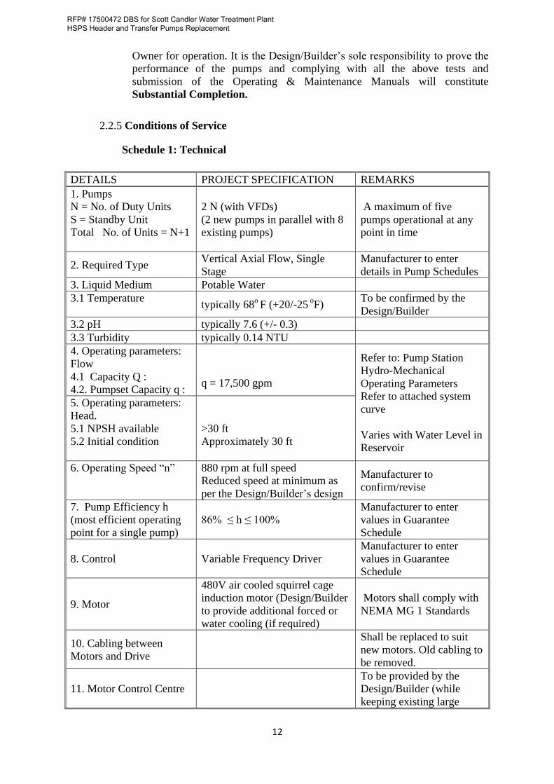
2.2.5 Conditions of Service
Schedule 1: Technical
DETAILS PROJECT SPECIFICATION REMARKS
1. Pumps
N = No. of Duty Units
S = Standby Unit
Total No. of Units = N+1
2 N (with VFDs)
(2 new pumps in parallel with 8
existing pumps)
A maximum of five
pumps operational at any
point in time
2. Required TypeVertical Axial Flow, Single
Stage
Manufacturer to enter
details in Pump Schedules
3. Liquid Medium Potable Water
3.1 Temperature typically 68
o F (+20/-25
oF)
To be confirmed by the
Design/Builder
3.2 pH typically 7.6 (+/- 0.3)
3.3 Turbidity typically 0.14 NTU
4. Operating parameters:
Flow
4.1 Capacity Q :
4.2. Pumpset Capacity q : q = 17,500 gpm
Refer to: Pump Station
Hydro-Mechanical
Operating Parameters
Refer to attached system
curve
Varies with Water Level in
Reservoir
5. Operating parameters:
Head.
5.1 NPSH available
5.2 Initial condition
>30 ft
Approximately 30 ft
6. Operating Speed “n” 880 rpm at full speed
Reduced speed at minimum as
per the Design/Builder’s design
Manufacturer to
confirm/revise
7. Pump Efficiency h
(most efficient operating
point for a single pump)
86% ≤ h ≤ 100%
Manufacturer to enter
values in Guarantee
Schedule
8. Control Variable Frequency Driver
Manufacturer to enter
values in Guarantee
Schedule
9. Motor
480V air cooled squirrel cage
induction motor (Design/Builder
to provide additional forced or
water cooling (if required)
Motors shall comply with
NEMA MG 1 Standards
10. Cabling between
Motors and Drive
Shall be replaced to suit
new motors. Old cabling to
be removed.
11. Motor Control Centre
To be provided by the
Design/Builder (while
keeping existing large
RFP# 17500472 DBS for Scott Candler Water Treatment Plant HSPS Header and Transfer Pumps Replacement
13
DETAILS PROJECT SPECIFICATION REMARKS
pumps operational)
2.3 Cranage
No overhead crane is available for offloading and installation purposes. It is the
responsibility of the Design/Builder to ensure that a suitable crane is provided for all
removal and installation purposes taking into consideration the space and load
constraints as the loading area is on top of the clear water tank which will have some
specific loads restrictions. It is the Design/Builder’s responsibility to do all necessary
calculations to ensure that these restrictions are not exceeded at any point in time
taking into consideration all the various climatic and load conditions.
2.4 ELECTRO-MECHANICAL SPECIFICATIONS
2.4.1 Scope
This scope covers the design, supply, delivery, installation, testing, commissioning and
guarantee of the electric motors for the Pumpsets. Installation and commissioning shall
occur as soon as the pumps are available. Shutdowns for periods of no more than 3
hours duration are accepted but must be prior arranged with the Owner.
This scope includes (but is not necessarily limited to) the following prime tasks and
responsibilities:
a) The evaluation of existing conditions and new work plans for use in the calculation
of HVAC loads to be used in design and selection of systems and equipment for
upgrade or replacement.
i) Design/Builder shall perform calculations for the upgraded pump room to
determine the HVAC loads and upgrade the ventilation systems and/or
provide cooling systems as necessary to allow the VFDs and Controls to
operate under manufacturers’ recommended conditions.
ii) Cooling and ventilation systems shall be designed and installed to meet the
2012 IMC and other applicable codes and requirements, per the Georgia's
Construction Code Program, including GA amendments, Energy Codes,
and any local codes or requirements that may be in effect.
b) The selection, manufacture and supply of suitable pumps complete with LV
(<1000 volt) motors including pump bases (soleplates);
c) Control instrumentation and signal cable terminating in a terminal box at the
pumpset;
d) Network communications between the VFDs and SCADA network interface;
e) All pipework and valves in accordance with the existing large pump assemblies;
f) Any other installation materials stated or implied to provide for a complete
installation in accordance with the Specifications, Drawings and Schedules
supplied; and
g) Commissioning after installation and supplying of Draft O&M manuals.
RFP# 17500472 DBS for Scott Candler Water Treatment Plant HSPS Header and Transfer Pumps Replacement
14
2.4.2 Equipment Supplied and Installation by Others
No equipment shall be supplied or installed by others. The Design/Builder will design
and supply all equipment but the following is preferred by the Owner:
a) PLCs: Rockwell Automation ControlLogix model L55, configured redundantly –
no exception
b) VFDs: Rockwell Automation PowerFlex
2.4.3 General Information
a) Only equipment based on proven technology and of high reliability shall be
considered for use.
b) All schedules included in this Document shall be completed in full and submitted
with the Proposal.
c) All relevant technical information regarding each component or item proposed
shall be reflected in the relevant section of the Request for Proposal
(supplemented by additional information where deemed necessary by the
Design/Builder), in order that the Owner can make a proper evaluation of the
Proposal.
d) After award preference will be given to locally Georgia manufactured equipment
and components. Should items not be locally manufactured, The Design/Builders
shall clearly identify these in their Proposal and state how maintenance backup
will be provided in future.
e) Where products of a particular supplier are specified, ‘equal’ products from other
suppliers may also be offered if approval for such products has been obtained
from the Owner.
2.4.4 Standards and Regulations
All materials and equipment shall be new and of the standard and quality specified.
The Design/Builder’s shall ensure that they are fully acquainted with the contents of
the applicable electrical codes and standards.
All wiring installations shall comply fully with NEMA WC5 and UL 83 as amended.
The design and manufacture of equipment and the complete installation shall be
carried out and tested in accordance with the latest issue or amendments of the
following Regulations, as applicable:
• DeKalb County’s Department of Watershed Management Design and Construction
Standards, latest edition.
• Georgia Environmental Protection Division Minimum Standards for Public Water
Systems
• Codes adopted and enforced by DeKalb County:
RFP# 17500472 DBS for Scott Candler Water Treatment Plant HSPS Header and Transfer Pumps Replacement
15
o International Building Code, 2012 Edition, with Georgia Amendments
o International Mechanical Code, 2012 Edition, with Georgia Amendments
o International Plumbing Code, 2012 Edition, with Georgia Amendments
o International Fire Code, 2012 Edition, with Georgia Amendments
o International Energy Conservation Code, 2009 Edition, with Georgia
Supplements and Amendments
o NFPA National Electrical Code, 2014 Edition
o 2012 NFPA 101 Life Safety Code with all Georgia State Amendments
o Georgia Accessibility Code Chapter 120-3-20, as amended
o 2010 ADA Standards for Accessible Design
o Any local electrical and I&C codes.
Where conflicting information to this bid document is contained in the above codes
and standards, this bid document will take precedence. The Design/Builder will inform
the Owner of any conflicting information found before continuing with the design or
ordering of any equipment.
Land and Easements:
No easements will be required as part of this project.
Utilities:
The Design/Builder will ensure that no utilities exists in the areas where breaking of
concrete, excavations for new services, penetrations through walls or drilling for
securing new supports, will take place. All necessary means will be exhausted to
detect, protect and ensure that no concealed or visible cable, pipe or duct is damaged
during the execution of the project.
Demolition and Removal of Concrete, Pipes and Cables
The work will include for the demolition and removal of concrete supports and new
openings in the tank roof for the installation of the new pumps. The existing opening
for the pumps in the tank roof will be reinforced concrete with steel bars and closed
off on removal of the pumps. The structure of the tank roof and adjacent columns will
be assessed by a professional structural engineer (Georgia licensed Professional
Engineer) and recommendation made (and implemented) regarding any additional
strengthening required for the cutting of two clearwell roof holes for the new pumps.
The Design/Builder shall include in his Cost Proposal the lump sum cost to:
• Remove and properly dispose of all redundant equipment and material from the
site including but not limited to the building rubble, concrete and old electrical
wires/conduits. All equipment removed, including pumps, motors pipework and
valves shall be disposed of by the Design/Builder. All steel reinforcing and
holding down bolts remaining above the concrete grade shall be cut off at least two
inched below the surface of the concrete and the holes shall be filled with a non-
shrink concrete repair mortar.
• Structural strengthening of the clearwell roof may be required to accommodate the
additional loads from the new pumps. Based on the Design/Builder’s calculations
additional roof reinforcement may be required and will be deemed to be included
RFP# 17500472 DBS for Scott Candler Water Treatment Plant HSPS Header and Transfer Pumps Replacement
16
for the lump sum cost. The cost will also include for any surveys and testing that
will be required to determine the extent of the current reinforcing and concrete
characteristics.
• Demolition activities shall be performed in accordance with the Technical
Specifications, Division 2.
2.4.5 Environmental and Site Conditions
The following information pertains to the Site and Works: