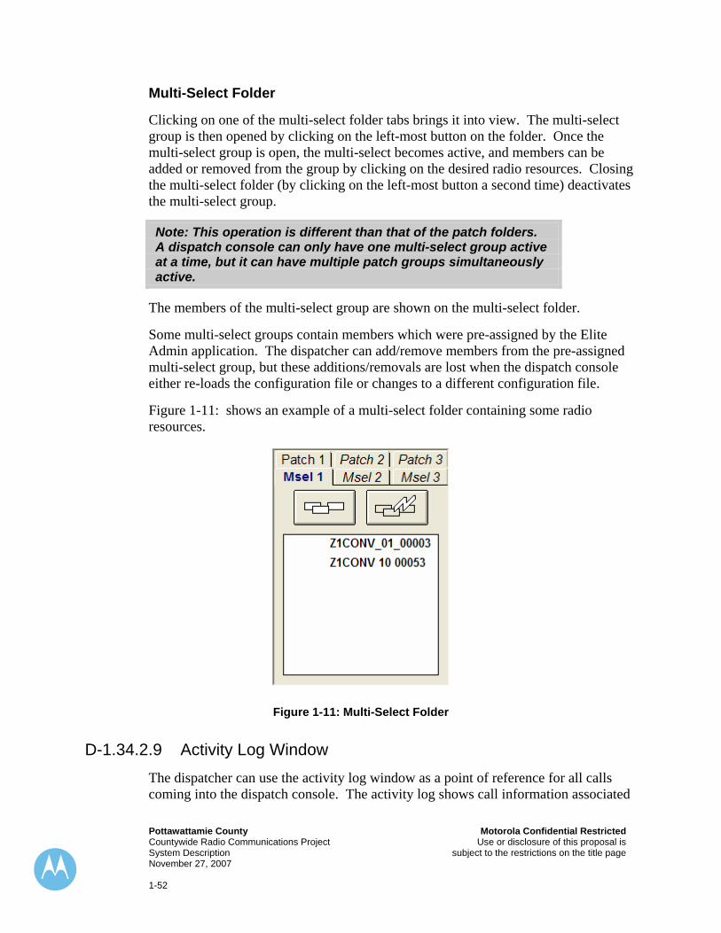
Motorola Confidential Restricted Pottawattamie County Use or disclosure of this proposal is Countywide Radio Communications Project subject to the restrictions on the title page System Description November 27, 2007 1-1 Exhibit D-1. System Description D-1.1.1 Introduction Motorola is pleased to present the following detailed description of the Pottawattamie County, Iowa Trunked Radio System. This system, and the associated digital technology behind it, has been designed specifically for the Fire Departments, Law Enforcement and other Agencies in Pottawattamie County. This system will provide an extremely reliable, easy to use integrated digital radio communications network that supports the following key features: ♦ Direct City and County Unit to Unit Inter-Agency Two Way Radio Communications ♦ On-Demand Reconfiguration of Talkgroups for Emergency and Disaster Communications ♦ Easy to Use, Frequency Efficient, Seamless Simulcast Radio Coverage ♦ Interoperability with selected users of other frequency bands and systems ♦ Countywide radio coverage using a portable radio with a Public Safety speaker Microphone (see coverage section) ♦ Enhanced Simulcast Tone and Voice Fire Paging system ♦ Countywide High Performance Data network The major elements that make up our total solution for Pottawattamie County include: ♦ 7 Site, 10 Channel, 800 MHz Digital Trunked ASTRO ® 25 network ♦ 7 Site, 800 MHz NPSPAC Mutual Aid system ♦ 4 Site, 1 channel, 700 MHz High Performance Data network ♦ Complete System Site Management & Alarm Monitoring Network
Transcript
Motorola Confidential Restricted Pottawattamie County Use or disclosure of this proposal is Countywide Radio Communications Project subject to the restrictions on the title page System Description November 27, 2007 1-1
Exhibit D-1. System Description
D-1.1.1 Introduction Motorola is pleased to present the following detailed description of the Pottawattamie County, Iowa Trunked Radio System. This system, and the associated digital technology behind it, has been designed specifically for the Fire Departments, Law Enforcement and other Agencies in Pottawattamie County. This system will provide an extremely reliable, easy to use integrated digital radio communications network that supports the following key features:
♦ Direct City and County Unit to Unit Inter-Agency Two Way Radio Communications
♦ On-Demand Reconfiguration of Talkgroups for Emergency and Disaster Communications
♦ Easy to Use, Frequency Efficient, Seamless Simulcast Radio Coverage ♦ Interoperability with selected users of other frequency bands and systems ♦ Countywide radio coverage using a portable radio with a Public Safety speaker
Microphone (see coverage section) ♦ Enhanced Simulcast Tone and Voice Fire Paging system ♦ Countywide High Performance Data network
The major elements that make up our total solution for Pottawattamie County include:
♦ 7 Site, 10 Channel, 800 MHz Digital Trunked ASTRO®25 network ♦ 7 Site, 800 MHz NPSPAC Mutual Aid system ♦ 4 Site, 1 channel, 700 MHz High Performance Data network ♦ Complete System Site Management & Alarm Monitoring Network
Pottawattamie County Motorola Confidential Restricted Countywide Radio Communications Project Use or disclosure of this proposal is System Description subject to the restrictions on the title page November 27, 2007 1-2
♦ Complete MCC7500 Dispatch Console system for the Main Dispatch ♦ CENTRACOM Gold Elite Console System upgrade that includes four (4)
Operator Positions and one (1) CEB for the Backup Dispatch
This single, integrated digital communications network has the ability to support both voice and data traffic on a common network infrastructure. This network supports seamless roaming throughout the entire coverage area. All calls, whether voice or data, are automatically sent to the user wherever they may be in the system.
Motorola has developed significant enhancements to the architecture of the ASTRO®25 network. This new architecture utilizes industry standard Packet Switched IP network links for connectivity between system elements.
The advantages of this configuration, and the technology and platforms used to implement it include:
♦ Digital Technology Compliant with APCO Project 25 Standards; Provides Open Architecture Network, and Multiple Sources for Subscriber Equipment
♦ Common Technology, Platform and Protocols for Both Voice and Data ♦ Coverage for Both Voice and Data is Comparable and Consistent, Utilizing
Common System Backbone ♦ Frequency Efficient FDMA Narrowband 12.5 KHz Operation ♦ Robust architecture provides reliability consistent with Mission Critical
applications ♦ Automatic Voice and Data call routing across entire network
This section contains the detailed description of the equipment included in Pottawattamie County’s system and a detailed overview of the ASTRO®25 architecture. It includes the following major subsections:
♦ System Configuration – Detailed overview of the specific equipment and configuration of all the major elements in our total solution for Pottawattamie County.
♦ ASTRO®25 System Architecture and RF Subsystems – Detailed Description of the ASTRO®25 system architecture.
♦ Mutual Aid Subsystem- Description of the Conventional Mutual Aid Subsystem ♦ Fire Paging Subsystem- Description of the VHF Fire Paging System ♦ ASTRO®25 Network Management – Description of ASTRO®25 System
Management tools and applications. ♦ Dispatch Console System– Detailed Description of the architecture and features
of the Console subsystem.
Motorola Confidential Restricted Pottawattamie County Use or disclosure of this proposal is Countywide Radio Communications Project subject to the restrictions on the title page System Description November 27, 2007 1-3
D-1.2 System Configuration As discussed in the introduction, Motorola is providing our ASTRO®25, 800 MHz digital trunked radio network to support Pottawattamie County’s communications needs. This ASTRO®25 trunked digital simulcast network will meet the county’s requirements for capacity, expansion, redundancy, and efficient use of frequencies. The system design provided for Pottawattamie County links 7 trunked simulcast remote sites into a single, seamless simulcast network. This single 10 channel simulcast subsystem offers Pottawattamie County the optimum coverage and throughput available with all channels at all sites. Motorola’s Redundant ASTRO®25 Simulcast Controller provides automatic routing of audio and calls, and allows your users to easily roam throughout the County.
Figure 1& 2 below illustrate the physical location of the major infrastructure components. Figure 1 shows the Pottawattamie County equipment and figure 2 shows the entire network once all other agencies have been upgraded and cut over.
Pottawattamie County Trunked Simulcast Radio Network
Site Router
McClellandSimulcast Remote
RF Site 2
MemorialSimulcast Prime
and RemoteRF Site 1 w/HPD
Carson Simulcast Remote
RF Site 3
Pottawattamie County Sites
Base Stations
T-1 over Private Microwave (for example only and not included)
TeNSr/800
Hancock Simulcast RemoteRF Site 5 w/HPD
KHIN Simulcast RemoteRF Site 4 w/HPD
Whippoorwill Simulcast Remote
RF Site 6Loveland
Simulcast RemoteRF Site 7 w/HPD
Switch
OmahaCivic Center
Main Dispatch7 Position MCC7500 console
and NM Client
CCGWs
Router
ECC MasterOPPD
Channel bank
Site Router
Switch
Backup Dispatch4 Position Gold Elite console
Avoca Analog VHF
Simulcast RF Site
Figure 1-1:
Pottawattamie County Motorola Confidential Restricted Countywide Radio Communications Project Use or disclosure of this proposal is System Description subject to the restrictions on the title page November 27, 2007 1-4
Omaha Regional Astro25 7.2 System
Redundant Zone Controllers
HPD Packet Data Gateway
Zone Network ManagementServers
Core RoutersRouter
CWREthernetSwitch
Gateway Routers
Leased T-1
40th & Nicholas HPD site
Titan Towers HPD Site
Leased T-1
156th & Maple HPD Site
T-1 Over Fiber
Douglas CoCEN
Security Servers
GGSNPottawattamie County Sites & Consoles
T-1 Over Microwave/Fiber
Douglas County Sites & Consoles
Leased T-1 & Fiber
Washington County Sites & ConsolesT-1 Over
Microwave/Fiber
T-1 Over Microwave/Fiber
OPPD Sites & Consoles
OPPDCEN
Router
IV&D Packet Data Gateway
POTTCoCEN
Figure 1-2
Motorola is providing our fourth generation Simulcast technology using atomic clock rubidium frequency standards to maintain frequency stability, and GPS satellite receivers to automatically maintain timing parameters. All of these enhancements, garnered over 4 generations, give users the best possible audio quality. To further increase redundancy and reliability, the Simulcast subsystem includes a fully redundant, automatic switchover simulcast trunking controller, to maintain 100% full-featured operation in the unlikely event of a failure.
D-1.3 System Access Time The Trunked system will allow users to access the system within 0.5 seconds, which is compliant with APCO Project 16 requirements.
D-1.4 ASTRO®25 Master Site *** The Pottawattamie County Simulcast Radio sub-system shares a single Master Site (Owned by Douglas Co, NE. Located the OPPD ECC facility) with other counties and agencies within the Omaha regional & metropolitan area. The Master Site equipment will be relocated to the ECC as part of this project. Douglas County is responsible for upgrading the existing Master Site from the current 7.0 release
Motorola Confidential Restricted Pottawattamie County Use or disclosure of this proposal is Countywide Radio Communications Project subject to the restrictions on the title page System Description November 27, 2007 1-5
platform to the 7.2 release platform. The upgrade to 7.2 is required to provide the compatibility with this add-on system for Pottawattamie County. It is expected that the Master Site is upgraded before or during the time Pottawattamie County is staged in Schaumburg, IL. Without the upgrade to 7.2, Pottawattamie County’s system will run in “Site Trunking”. ***
The Master Site is the heart of an ASTRO®25 Communications Network. It contains the equipment necessary to control and manage both site operation and subscriber information. It is the single point in the system where all subsystems converge and provides user interfaces in the form of radio consoles, Zone Manager, diagnostics, site management, and subscriber access. The Master Site for Pottawattamie County’s system will be located at the OPPD ECC facility. An ASTRO®25 Controller and Ambassador Electronics Bank (AEB or “audio switch”), is located in the Master Site. This site is remotely located from the Pottawattamie County Simulcast Prime Site and Subsystem.
Other equipment located at the ASTRO®25 Master Site includes the following:
♦ ASTRO®25 System Manager Servers and associated hardware and software; owned by Douglas County and located at the ECC; The ASTRO®25 Manager provides for access to all of the system information entry, supports the various dispatch and reports applications and system diagnostics. Pottawattamie County will have a management terminal which is included in this proposal. The terminal will be located at the Pottawattamie Co. Dispatch Center.
♦ FullVision Integrated Network Manager (INM) Local Server and application software. FullVision INM provides an integrated view of system fault management. Only two sessions of FullVision can be executed concurrently. Additional users who need access to system fault management can execute a web browser to access system fault management information.
♦ MOSCAD Graphics Master Central. The MOSCAD system is an alarm and control system for monitoring the remote sites and other system support equipment. Pottawattamie County will have a Graphics Work Station terminal located at the Pottawattamie Co. Dispatch Center.
D-1.5 ASTRO®25 Zone Controller A redundant ASTRO®25 Zone Controller is located at the Master Site. This controller manages the call routing in the ASTRO®25 Simulcast system, dispatch console system, and the mobile and portable radios. The Zone Controller interfaces to the ASTRO®25 system through redundant network links. The architecture and connectivity is described in detail in following sections.
The Zone Manager consists of a database server, and PC-based User Terminals. The ASTRO®25 LAN has the capability of supporting a total of thirty (32) local or remote
Pottawattamie County Motorola Confidential Restricted Countywide Radio Communications Project Use or disclosure of this proposal is System Description subject to the restrictions on the title page November 27, 2007 1-6
user terminals. Pottawattamie County will have one terminal located in the Dispatch center.
D-1.6 ASTRO®25 Embassy Network and Integrated Console System To take full take advantage of all the capabilities of the ASTRO®25 trunked digital voice system, as well as maintaining the County’s other dispatch needs, Motorola is providing an upgrade to the existing CENTRACOM Gold Elite console system located in Pottawattamie County’s existing Dispatch Center at the Courthouse. The specific upgrade configuration provided is detailed later in this system description. Because the CENTRACOM Gold Elite console subsystem is tightly integrated to the ASTRO®25 trunked digital voice radio system, its relationship to the system is also noted here. The Motorola Ambassador Electronics Bank (AEB) serves as the center of this integrated network, linking together all console system audio resources, interconnect audio and the trunked system.
D-1.7 Ethernet LAN Switches and Routers Operation and management of an ASTRO®25 system requires communication between various subsystems and subsystem components. This is accomplished over a Local Area Network (LAN) and Wide Area Network (WAN). The primary components of this LAN/WAN system are owned by Douglas County NE and located at the OPPD ECC Master Site in Omaha NE. These components include a series of LAN and WAN switches and various IP routers that make up a fully redundant Master Site network.
***The configuration of the Master Site hardware and software is subject to change and will continue to be enhanced as future releases of hardware and software become available.***
D-1.8 ASTRO®25 Elite LAN The ASTRO®25 Elite LAN supports the dispatch console operations within the network. The Console Database Manager and Alias Database Manager are software applications that run on the CENTRACOM Gold Elite Server under the Windows 2003 Server OS. The Elite Sever is located at the Master Site and provides programming and alias information to the dispatch console operator positions. Console Database programming information can be accessed remotely through the LAN network.
Motorola Confidential Restricted Pottawattamie County Use or disclosure of this proposal is Countywide Radio Communications Project subject to the restrictions on the title page System Description November 27, 2007 1-7
D-1.9 ASTRO®25 Zone Manager (OZM) The ASTRO®25 Zone Manager consists of several hardware and software components in “client server” architecture. Various Zone Manager software functions and processes are resident on either the Zone Controller, or the Database Server. Each of these hardware elements is a device on the Zone Manager LAN. User Terminals provide access and a view to the various software applications and functions.
A new Network Manager User Terminal is quoted for Pottawattamie County’s system. The terminal will be located at the Pottawattamie County Dispatch center. The terminal is connected to a KVM switch along with the MOSCAD Graphic Work Station. All of the system’s configuration, diagnostics and dynamic functions are accessed through the terminal.
Specific software applications that reside on the ASTRO®25 Manager are licensed on an individual, simultaneous user basis. For example, to access the Configuration Management application at two locations simultaneously, two licenses are required. The application may then be accessed simultaneously at two user terminal locations.
The number of software licenses indicates how many simultaneous sessions of that application may be concurrently accessed from any User Terminal locations. Pottawattamie County’s Zone Manager is configured with the following software licenses.
♦ One (1) Infrastructure Configuration/User Management Reports ♦ One (1) Historical Reports (system performance reports) ♦ One (1) Affiliation User Reports ♦ One (1) ZoneWatch Grid & Control (real time channel assignments) ♦ One (1) Radio Control Manager including:
• Basic Radio Control Manager • Dynamic Regrouping • Status Capability
Additional licenses can be purchased and implemented if Pottawattamie County finds the need for additional capabilities.
D-1.10 User Configuration Subsystem (UCS) The User Configuration Subsystem (UCS) is an additional subsystem in ASTRO®25 systems that provides access to the radio and infrastructure configuration database. The UCS also consists of several hardware and software components. Hardware components consist of a Database Server, and User Server. As with the Zone
Pottawattamie County Motorola Confidential Restricted Countywide Radio Communications Project Use or disclosure of this proposal is System Description subject to the restrictions on the title page November 27, 2007 1-8
Manager, the User Terminal provides access and a view to the various software applications and functions. The User Configuration Subsystem is configured from the Network Management Terminal at the Pottawattamie County Dispatch Center.
D-1.11 FullVision Integrated Network Manager To meet the ASTRO®25 system’s requirements for a high level Network Management tool, Motorola provided the FullVision™ Integrated Network Manager. The FullVision™ Integrated Network Manager (FullVision INM) is a communications network management tool based on Hewlett-Packard's OpenView (HPOV) Network Node Manager 250. HPOV is a standard network management software application that uses the industry standard Simple Network Management Protocol (SNMP) to communicate with the elements it manages. Use of standard protocols facilitates the management of all devices from a central location.
Only two sessions of FullVision can be executed concurrently. Additional users who need access to system fault management can execute a web browser to access system fault management information.
D-1.12 Trunked Simulcast Subsystem As noted, Motorola is providing the use of simulcast in order to utilize all 10 channels at each transmitter site that will offer the most frequency efficient design while providing the best coverage possible for the County. The simulcast configuration is comprised of seven (7) RF sites with 10 channels per site. Keep in mind, a seven site simulcast system appears as one simulcast cell to all the users and the Network Manager. There is no need to change modes on the radios or the console when a user roams throughout the coverage area or from site-to-site.
The Prime Site for the simulcast system will be located at the Memorial Site. This site employs additional equipment that synchronizes and broadcasts information to all the remote sites in order to simulcast the information. The Prime Site is located at a separate site from the ASTRO®25 Master site. This provides an additional level of protection to the trunked system.
D-1.12.1 Simulcast Prime Site The Prime Site for the simulcast system is equipped with redundant Simulcast Prime Site Controllers and switching equipment for an added level of redundancy. The controllers and digital audio information are interfaced into the network using redundant Motorola ST6000 Prime Site Routers over two T1 circuits. The T1 circuits terminate into the Cooperative WAN Router patch panels at the Master Site. The main T1 link is connected to Prime Site Router #1. This Prime Site Router also has hardwired WAN connections to the remote sites that provide management links for
Motorola Confidential Restricted Pottawattamie County Use or disclosure of this proposal is Countywide Radio Communications Project subject to the restrictions on the title page System Description November 27, 2007 1-9
the remote site equipment. Note that when the main T1 link is down, the Prime Site Router #2 is active. This backup router does not have separate WAN connections to the simulcast remote sites and therefore remote site management is not possible, although voice communication is unaffected.
The Prime and Remote Sites are powered by 48 VDC power systems. These power systems include DC rectifier power supplies and batteries. This eliminates the need for a site UPS and provides a more reliable power source for all of the Prime and Remote site equipment.
The Prime Site includes the following hardware:
♦ Ten (10) P25 ASTRO-TAC 9600 Voting Comparators ♦ Four (4) Digitac Analog Voting Comparators ♦ One (1) CSCI analog simulcast audio shelf ♦ One set of two (2) GCP8000 Redundant Simulcast Prime Site Controllers ♦ One (1) Redundant Rubidium GPS Site Reference with expansion shelf ♦ One set of two (2) Redundant Prime Site Routers ♦ Two (2) Prime Site Ethernet Switches ♦ Three (3) TeNSr/800 Digital Channel Banks ♦ One (1) MOSCAD Remote Terminal Unit ♦ One (1) 48VDC to 12VDC converter ♦ DC Distribution and breakers as needed ♦ Four (4) 19” Open Relay Racks
In addition, the Prime Site will also include the following Co-located Remote Site equipment:
♦ Ten (10) channel GTR8000 Base Radio system; 100 watt, 800 MHz, P25 ASTRO Digital Linear Simulcast Stations
♦ One (1) Co-located Remote Site Ethernet Switch ♦ Two (2) Quantar 800 MHz Mutual Aid base stations ♦ One (1) Quantar VHF Simulcast paging base station ♦ One (1) Quantar VHF Simulcast Law Mutual Aid base station (Memorial) ♦ Three (3) high gain, Omni-directional VHF Transmit/Receive Antenna systems ♦ Three (3) VHF transmitter combiners ♦ One (1) high gain, Omni-directional 800 MHz Transmit Antenna (Trunked and
ICALL channels) ♦ One (1) high gain, Omni-directional 800 MHz Transmit Antenna (ITAC
Channels)
Pottawattamie County Motorola Confidential Restricted Countywide Radio Communications Project Use or disclosure of this proposal is System Description subject to the restrictions on the title page November 27, 2007 1-10
♦ One (1) high gain, Omni-directional 800 MHz Receive Antenna (Trunked and 800 Mutual Aid)
♦ One (1) high gain, Omni-directional 700/800 MHz Transmit and Receive Antenna (HPD Sites only)
♦ One (1) 800 MHz Transmit Combiner with 250 KHz frequency spacing (Trunked and ICALL channels)
♦ One (1) 800 MHz Transmit filter with 5 MHz frequency bandwidth (Mutual Aid ITAC channels)
♦ One (1) 700/800 MHz 16 Port Receiver Multicoupler w/Tower Top Amplifier ♦ Transmit antenna line and connectors as needed ♦ Receive antenna line and connectors as needed ♦ Tower top test port antenna line and connectors as needed ♦ One (1) 300 Amp hour battery system providing at least 30 minutes back up
power to the Prime and Co-located Remote Site equipment ♦ Two (2) 420 Watt 48VDC to 120 VAC Inverters with Static Bypass Switch
(powers the router and switches from 48 VDC battery system) ♦ Eleven (11) 30 Amp -48 VDC Switch Mode Rectifiers powers the site and
charges batteries ♦ DC Distribution and breakers as needed ♦ Four (4) 19” Open Relay Racks ♦ Set of Spares as needed
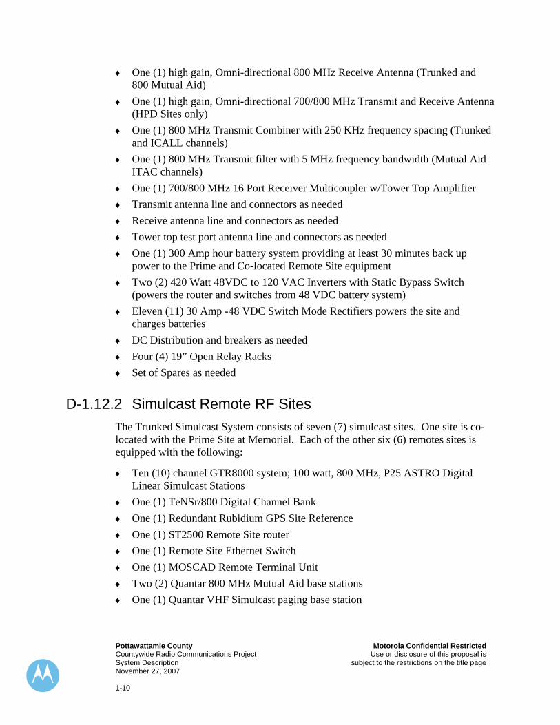
D-1.12.2 Simulcast Remote RF Sites The Trunked Simulcast System consists of seven (7) simulcast sites. One site is co-located with the Prime Site at Memorial. Each of the other six (6) remotes sites is equipped with the following:
♦ Ten (10) channel GTR8000 system; 100 watt, 800 MHz, P25 ASTRO Digital Linear Simulcast Stations
♦ One (1) TeNSr/800 Digital Channel Bank ♦ One (1) Redundant Rubidium GPS Site Reference ♦ One (1) ST2500 Remote Site router ♦ One (1) Remote Site Ethernet Switch ♦ One (1) MOSCAD Remote Terminal Unit ♦ Two (2) Quantar 800 MHz Mutual Aid base stations ♦ One (1) Quantar VHF Simulcast paging base station
Motorola Confidential Restricted Pottawattamie County Use or disclosure of this proposal is Countywide Radio Communications Project subject to the restrictions on the title page System Description November 27, 2007 1-11
♦ One (1) Quantar VHF Simulcast Law Mutual Aid base station (McClelland, Carson, Avoca)
♦ One (1) high gain, Omni-directional VHF Transmit/Receive Antenna ♦ One (1) high gain, Omni-directional VHF Transmit/Receive Antenna
(McClelland) ♦ Two (2) VHF transmitter combiners (McClelland) ♦ One (1) high gain, directional 800 MHz Transmit Antenna (Trunked and ICALL
channels) ♦ One (1) high gain, directional 800 MHz Transmit Antenna (ITAC channels) ♦ One (1) high gain, directional 800 MHz Receive Antenna (Trunked and 800
Mutual Aid channels) ♦ One (1) high gain, Omni-directional 700/800 MHz Transmit and Receive Antenna
(HPD Sites only) ♦ One (1) 800 MHz Transmit Combiner with 250 KHz frequency spacing (Trunked
and ICALL channels) ♦ One (1) 800 MHz Transmit filter with 5 MHz frequency bandwidth (Mutual Aid
ITAC channels) ♦ One (1) 700/800 MHz 16 Port Receiver Multicoupler w/Tower Top Amplifier ♦ Transmit antenna line and connectors as needed ♦ Receive antenna line and connectors as needed ♦ Tower top test port antenna line and connectors as needed ♦ One (1) Redundant Rubidium GPS Reference ♦ One (1) S2500 Remote Site IP Router ♦ One (1) Hewlett Packard 24 port Network Switch ♦ One (1) TenSr/800 Digital Channel Bank ♦ One (1) MOSCAD Remote Terminal Unit ♦ One 270 Amp-hour battery system providing at least 30 minutes back up power to
the remote site equipment ♦ One (1) 420 Watt 48VDC to 120 VAC Inverter with Static Bypass Switch
(powers the router and switches from 48 VDC battery system) ♦ Ten (10) 30 Amp -48 VDC Switch Mode Rectifiers ♦ Four (4) 19” Open Relay Racks
The VHF simulcast systems utilize an additional site located in Avoca, IA. This site provides an 8th simulcast site for the VHF paging system and the 5th site for the Law Mutual Aid channel. This site contains the following equipment:
♦ One (1) TeNSr/800 Digital Channel Bank
Pottawattamie County Motorola Confidential Restricted Countywide Radio Communications Project Use or disclosure of this proposal is System Description subject to the restrictions on the title page November 27, 2007 1-12
♦ One (1) Redundant Rubidium GPS Site Reference ♦ One (1) ST2500 Remote Site router ♦ One (1) Remote Site Ethernet Switch ♦ One (1) MOSCAD Remote Terminal Unit ♦ One (1) Quantar VHF Simulcast paging base station ♦ One (1) Quantar VHF Simulcast Law Mutual Aid base station ♦ One (1) high gain, Omni-directional VHF Transmit/Receive Antenna system ♦ One (1) VHF transmitter combiner ♦ One 270 Amp-hour battery system providing at least 30 minutes back up power to
the remote site equipment ♦ One (1) 420 Watt 48VDC to 120 VAC Inverter with Static Bypass Switch ♦ Transmit antenna line and connectors as needed ♦ Receive antenna line and connectors as needed
The 8 Sites selected in the simulcast system are:
1. Memorial Tower Site (Prime and Remote Site 1) 2. McClelland Tower Site (Remote Site 2) 3. Hancock Tower Site (Remote Site 3) 4. Carson City Tower Site (Remote Site 4) 5. KHIN TV36 Tower Site (Remote Site 5) 6. Whippoorwill Tower Site (Remote Site 6) 7. Loveland Tower Site (Remote Site 7) 8. Avoca Tower Site (Paging and Law Mutual Aid Remote Site 8)
D-1.12.3 Dispatch Console Sites There will 2 sites with dispatch console systems:
1. Main Dispatch 2. Backup Dispatch
These sites contain the following equipment:
Main Dispatch
♦ One (1) TeNSr/800 Digital Channel Bank ♦ Seven (7) MCC7500 Secure Dispatch Operator Positions ♦ One (1) GCP8000 Conventional Site Controller ♦ Six (6) Conventional Channel Gateways ♦ Two (2) ST2500 Console Site Routers
Motorola Confidential Restricted Pottawattamie County Use or disclosure of this proposal is Countywide Radio Communications Project subject to the restrictions on the title page System Description November 27, 2007 1-13
♦ One (1) MOSCAD I/O unit ♦ Two (2) LAN Switches ♦ Seven (7) XTL5000 Trunked Consolettes (provides backup communications) ♦ One (1) XTL5000 Conventional Consolette (provides dispatcher monitoring of
co-channel users on 800 Mutual Aid ♦ One (1) Control Station Combiner ♦ One (1) Receiver Multicoupler ♦ One (1) Network Manager Terminal ♦ One (1) MOSCAD Graphics Workstation ♦ One (1) Customer Network Interface ♦ One (1) Raven M4 VOX shelf ♦ Three (3) 7 ½ foot 19” Open Relay Racks ♦ One (1) 8.4 KW UPS
Backup Dispatch
♦ One (1) TeNSr/800 Digital Channel Bank ♦ Four (4) CentraCom Gold Elite software refresh and upgrade to Astro25 Trunking ♦ Four (4) XTL5000 Trunked Consolettes (provides backup communications) ♦ One (1) XTL5000 Conventional Consolette (provides monitoring co-channel
users on 800 Mutual Aid ♦ One (1) Control Station Combiner ♦ One (1) Network Manager Terminal ♦ One (1) Raven M4 VOX shelf (provides control of audio traffic on conventional
channels ♦ One (1) 7 foot 19” Open Relay Rack ♦ One (1) 8.4 KW UPS
D-1.12.4 Power Requirements Power for the simulcast site equipment is provided by a 48 VDC power system. The equipment provided for each RF site includes the 48 VDC rectifier charging equipment and batteries sufficient to operate the stations and equipment for at least 30 minutes in the event of an AC power failure. Site equipment that operates from 120 VAC is powered by a 420 Watt DC to AC inverter, providing the same amount of operating time during a power failure. The 12VDC equipment at the Prime Site is powered by a 48VDC to 12VDC converter. The 30 minutes backup time on batteries provide more than adequate backup time until the customer provided site backup
Pottawattamie County Motorola Confidential Restricted Countywide Radio Communications Project Use or disclosure of this proposal is System Description subject to the restrictions on the title page November 27, 2007 1-14
generator becomes fully operational. The inverters have a static bypass feature that allows switching directly to AC power for service.
Power for the DC rectifier systems is to be provided by the customer in customer provided shelters of adequate size and with adequate cooling systems. In each case, a site rack plan has been provided with the amount of customer provided circuits labeled at the top of each rack. The cooling requirements will be provided during the Detailed Design Review.
The dispatch centers are intended to be entirely AC powered from customer provided circuits backed up by UPS systems and generators. Each dispatch center has been provided with a UPS capable of powering only the Motorola provided two way radio and HPD equipment provided in this response to and as per the RFP dated October 28, 2007. It is the customer’s responsibility to provide all AC circuits and adequate power for all the dispatch and RF sites.
D-1.12.5 Antenna Systems Special consideration has been given to the design of the antenna systems. Antenna sites were selected based on a coverage prediction using the requirements provided by you, the customer. Antennas were selected to maximize coverage throughout the County. The entire coverage design and related hardware in this proposal relies upon the capability of each antenna tower to support the predetermined antenna and transmission lines at the described heights at the sites previously identified. Motorola has performed no tower analysis as of the proposal date. Tower modifications or any changes to the antenna network design will require a change order at additional cost.
The receive antenna network includes a receiver multicoupler, and a tower mounted preamplifier for optimum reception of portable units. The receiver multicoupler employed in this design has been specially designed for improved performance and a high level of intermodulation protection. The amplifier is provided with a test port that provides ease of testing.
This system is designed to provide coverage for portable radios. All RF power from the mobile units must be limited to 5 watts ERP. All control station transmitted RF power must also be limited to 5 watts ERP. Failure to deploy the subscriber units with these critical parameters properly set may result in interference and anomalies such as “cross talk”.
The specific antenna design will be a discussion topic during the Detailed Design Review (DDR). The following are the antenna height requirements, latitude and longitude and height above mean sea level for the Trunked RF sites:
Motorola Confidential Restricted Pottawattamie County Use or disclosure of this proposal is Countywide Radio Communications Project subject to the restrictions on the title page System Description November 27, 2007 1-15
Radio Towers - Total number of sites: 7
Tower Latitude Longitude Datum AMSL (m, ft) AAT (m, ft)
Carson 41 14 11 N 95 24 44 W WGS84 364, 1194.3 1.1, 3.4 Transmit ERP (dBm, W) Antenna Ant HT (m, ft) HAAT (m, ft)
Pottawattamie County Motorola Confidential Restricted Countywide Radio Communications Project Use or disclosure of this proposal is System Description subject to the restrictions on the title page November 27, 2007 1-16
D-1.12.6 NPSPAC Mutual Aid Solution One base station will be set up with the National Mutual Aid Calling channel while a second repeater will be programmed to select any one of the four common TAC channels. Both of these base stations are simulcast throughout the county. This configuration is intended to be deployed at all of the Trunked Simulcast Sites as per the State of Iowa 800 MHz Public Safety Radio Communications Plan. The ICALL repeater station is combined into the Trunked System transmitter combiner and utilizes one transmit antenna system. The ITAC repeater is capable of multiple frequencies and utilizes a bandpass transmit filter and separate transmit antenna system. The receivers share the trunked system receiver multicouplers. While the ICALL channel is always available, only one of the ITAC channels can be utilized throughout the county at any given time. All the base stations are controlled by the dispatch consoles using 4-Wire circuit cards through the new TeNSr channel bank system. All repeater stations are capable of repeater setup and knockdown. All repeaters are normally in knockdown mode until a call is assigned to a TAC channel by the dispatcher. Since these channels are shared with other counties, a monitor receiver is provided to monitor the channels at the dispatch consoles for co-channel user activity.
D-1.12.7 VHF Fire Paging Simulcast Subsystem The VHF Fire Paging subsystem uses a single simulcast base station located at each of the trunked radio sites. One additional VHF paging site will be located in Avoca. The system is designed to accommodate either narrowband or wideband analog tone & voice paging within the VHF frequency range 154-174 MHz. Each of the trunked radio sites and the Avoca site will house a VHF simplex simulcast conventional base station with tower mounted antenna system. A two (2) channel transmitter combiner is provided at each site where there is a paging base and a Law Mutual Aid base. The frequency separation between these 2 transmitters must be at least 500 KHz. Due to the lack of frequency information, intermodulation studies were not completed and interference free operation is not ensured. Additional filtering and combining equipment may be required due to presence of intermodulation and/or interference found during implementation. If a problem arises, additional equipment and services will be offered at additional cost during implementation.
The system design is intended to provide countywide paging coverage although there is no coverage guarantee for analog tone & voice paging. Operation of the paging system is through the existing CentraCom Gold Elite console system(s) and the new MCC7500 console system. See the paging section of the dispatch console descriptions for more information.
Motorola Confidential Restricted Pottawattamie County Use or disclosure of this proposal is Countywide Radio Communications Project subject to the restrictions on the title page System Description November 27, 2007 1-17
D-1.12.8 VHF Law Mutual Aid Simulcast Subsystem The VHF Law Mutual Aid subsystem uses a single simulcast base station located at four (4) of the Trunked radio sites. The subsystem is designed to utilize the frequency 155.475 MHz and shares an antenna system with the paging base station at each of the sites. A two (2) channel transmitter combiner is provided at each site where there is a paging base and a Law Mutual Aid base. The frequency separation between these 2 transmitters must be at least 500 KHz. Due to the lack of frequency information, intermodulation studies were not completed and interference free operation is not ensured. Additional filtering and combining equipment may be required due to the presence of intermodulation and/or interference found during implementation. If a problem arises, additional equipment and services will be offered at additional cost during implementation. The coverage provided by the site layout suggested in the RFP mainly provides mobile coverage throughout the County. No coverage guarantee is provided with this subsystem. The following sites were selected for this subsystem as per the RFP:
♦ Memorial ♦ McClelland ♦ Carson ♦ Avoca
Each of these four radio sites will house an additional VHF simplex simulcast conventional base station. Operation of the subsystem is through the existing CentraCom Gold Elite console system and the new MCC7500 console system.
D-1.12.9 Other VHF Mutual Aid Stations Where required, additional VHF antenna networks have been included to provide for the additional VHF base stations listed in the RFP dated October 28, 2007. Each base station is provided with a separate antenna. Due to the lack of frequency information, intermodulation studies were not completed and interference free operation is not ensured. Additional filtering and combining equipment may be required due to the presence of intermodulation and/or interference found during implementation. If a problem arises, additional equipment and services will be offered at additional cost during implementation.
The sites where additional VHF stations have been identified include:
♦ Memorial - 2 additional antenna systems ♦ McClelland – 1 additional antenna system
Pottawattamie County Motorola Confidential Restricted Countywide Radio Communications Project Use or disclosure of this proposal is System Description subject to the restrictions on the title page November 27, 2007 1-18
D-1.12.10 Site Trunking and Failsoft Two backup modes of operation are available within the Simulcast Trunked Site; Site Trunking and Failsoft. Each mode provides a backup means of communication upon specific systemic or link failures. Each mode of operation allows the simulcast site to provide the same coverage and deliver the same audio quality as in the “Wide Area” mode of operation. Each backup mode requires the dispatchers to use the appropriate backup control station assigned to that dispatch position. These backup control station resources will be programmed into a separate folder on the dispatch console for ease of use.
D-1.12.10.1 Site Trunking Site Trunking is a term used to describe the Trunking status of an RF site or sub-system. Keep in mind, a seven site simulcast system appears as one simulcast cell to the users and the Network Manager. Normally, the RF site runs in Wide Area mode. Wide Area mode provides for direct radio communications with the dispatch consoles and other sites within the ASTRO®25 network. Direct communications denotes there is physical and therefore logical connectivity to the RF Site from the Master Site. There are a number of conditions that could cause a Site Trunking condition. Site Trunking can occur within the Simulcast Sub-System. One example is the loss of both T1 links between the Master WAN Switch and the Prime Site Routers. Another more uncommon situation would be a total loss of the Master Site. When the simulcast site enters Site Trunking, communication between users in the field does not change. Only the direct “wire-line” connectivity to the dispatch console is affected. Mobile and portable radios that have a display will alternate the display with the words “Site Trunking” and the current talkgroup. Most Trunking features are retained in Site Trunking such as PTT ID, busy queue and callback, talkgroup priority, private call, call alert (page) and others. Conventional operations are not affected in Site Trunking although Trunked talkgroup patching is not available. Emergency Alarm is processed at the dispatch console in Site Trunking. When an emergency talkgroup setup is required in Site Trunking, users in the field press the emergency button. This will send an alert to the dispatcher. When the radio user pushes the PTT button, a talkgroup Emergency Call is setup. In Site Trunking the dispatch console is not capable of processing calls through the main dispatch folder since there may be no physical link from the RF site to the Master. Therefore, a total of 7 backup control stations (XTL5000 Consolettes) are provided and connected to the CentraCom CEB and the MCC7500 CCGWs to allow the dispatchers to operate from a second “backup” folder on the dispatch consoles. The consolettes interface to the consoles through their respective Base Interface Modules and ASTRO Console Interface Modules or CCGWs. The BIM or CCGW provides a connection to the consolette for analog audio. The ACIM provides a data interface that forwards received PTT ID and Emergency Alarm and Call indications to the channel resource in the backup dispatch folder on the CentraCom console only. Emergency Alarm is
Motorola Confidential Restricted Pottawattamie County Use or disclosure of this proposal is Countywide Radio Communications Project subject to the restrictions on the title page System Description November 27, 2007 1-19
not activated in the backup mode if that talkgroup is involved in call activity during the time the alarm is sent. Emergency Call operates as normal regardless of call activity. Each main dispatch position has a dedicated consolette to use as a backup means of communication during a Site Trunking event. While the dispatcher is using the channel resource that controls the consolette, the Simulcast System handles the PTTs from the console in the same manner as the field radios. Therefore, no console priority is available in Site Trunking. An indication on the dispatch console provides the trunked site status in the event the system enters Site Trunking. The FullVision diagnostic display provides an indication to the System Manager when the system is in Site Trunking or Failsoft.
D-1.12.10.2 Failsoft Failsoft is a condition of the Simulcast Sub-system that can occur if there is no Simulcast Site Controller available for call processing. Normally the redundant GCP8000 Simulcast Controllers in the Prime Site act as a proxy in Wide Area mode. In Site Trunking mode, the controllers manage call processing and resource assignments. If both controllers fail, the simulcast system reverts to Failsoft. While in Failsoft, the simulcast sub-system uses all the available channels as conventional repeaters, there is no control channel on the air. Instead, all the repeaters transmit at every site in simulcast mode but with a continuous inaudible Failsoft word modulated on the RF carrier. Radios in the field are preprogrammed with a Failsoft frequency. Upon loss of the control channel, the radios search for the “Failsoft word” on the preprogrammed Failsoft frequency. Each radio finds its Failsoft channel and a sinuous but distinctive “Failsoft tone” is periodically output from the radio’s speaker. Mobile and portable radios that have a display will alternate the display with the word “Failsoft” and the current talkgroup. The unit is then allowed to transmit upon PTT. If multiple agencies share a Failsoft frequency, the users hear each other’s conversations during Failsoft. No trunked features are preserved in Failsoft. It is simply push to talk, release to listen. Subscriber units and the dispatch console can be configured to select different Failsoft channels during Failsoft operation by selecting a different talkgroup. Subscriber units continue to show their assigned ID or alias on the displays of the other units and the dispatch console. The dispatchers must move to the backup folder on the dispatch consoles. The backup folder contains channel resources that connect to the backup control stations. The backup control stations automatically find their respective Failsoft channels and continue to operate on the selected talkgroup. An indication on the dispatch console provides the Failsoft status in the event the system enters Failsoft. The FullVision diagnostic display provides an indication to the System Manager when the system is in Site Trunking or Failsoft. If particular talkgroups are permitted to roam from site to site, they will move to a wide area site (i.e. Douglas County). Only talkgroups that cannot roam to other sites can go to Failsoft. Special consideration must be given to the main dispatch talkgroups and possibly not allow the units to roam from site to site when on specific dispatch talkgroups.
Pottawattamie County Motorola Confidential Restricted Countywide Radio Communications Project Use or disclosure of this proposal is System Description subject to the restrictions on the title page November 27, 2007 1-20
D-1.13 MOSCAD Alarm and Control
D-1.13.1 Graphic Master Central (GMC) & Graphic Work Station (GWS) The MOSCAD system monitors the environmental status of the RF and console sites in the system. Remote diagnostic functions are provided for devices that communicate using serial data connections at each site. The system is also capable of providing remote control functions. The Graphics Work Station interfaces to the site LAN and communicates with the Graphics Master Central located at the Master Site. The GWS is intended to be located at the main dispatch center. The MOSCAD SDM3000 Remote Terminal Units (RTUs) communicate to the GMC via the IP Gateway at the Master Site. The GWS provides a graphic representation of the County’s system and the devices being monitored by the RTU’s.
The chart on the following page shows highlighted devices that are monitored at each site as a standard where applicable. The additional devices can be monitored by the MOSCAD system and/or an existing alarm monitor system. The final programming will be decided during the DDR. Any modifications to this plan after the DDR shall be considered a change order and will require additional cost to implement.
Motorola Confidential Restricted Pottawattamie County Use or disclosure of this proposal is Countywide Radio Communications Project subject to the restrictions on the title page System Description November 27, 2007 1-21
Element NameBuilding-inDescription 48DI # Severity State Persistence
DoorIntrusion 1 Major N/C 2 Door2Intrusion 2 Major N/C 2
TowerTopAmpl 35 Minor N/O 2 Breaker 36 Critical N/O 2-48V-in
Description 48DI # Severity State Persistence Distribution 37 Minor N/C 2
Rectifier 38 Major N/C 2 Converter 39 Minor N/C 2
High Sys Voltage 40 Major N/C 2 System 41 Minor N/C 2
Customer Specific ElementDescription 48DI # Severity State Persistence
42-48 for NFMGenerator Common Fault 42 Major N/O 2
N/O --- Normally OpenN/C --- Normally Closed
Pottawattamie County Motorola Confidential Restricted Countywide Radio Communications Project Use or disclosure of this proposal is System Description subject to the restrictions on the title page November 27, 2007 1-22
In addition, the MOSCAD provides interfaces to devices that communicate over an RS-232 data link and interfaces them to the IP network. The specific devices are as follows:
♦ Premisys (TeNSr) channel banks ♦ TRAK GPS ♦ Analog Quantar Base Stations ♦ Central Electronics Banks at the Backup Dispatch Center.
Alarms and indications from each of these devices will be monitored at the remote site, and upon detection of alarm, will be transferred to the GMC & GWS across the infrastructure network. The GWS presents the System Manager with a real-time view of the health of these devices in the system.
D-1.14 WAN Link Requirements and T1 Connectivity The proposed Pottawattamie County ASTRO®25 and Mutual Aid network is comprised of several sites connected by T1 circuits. No microwave, fiber, leased T1 or any other connectivity that is necessary for proper system functionality is included with this proposal and therefore it is Pottawattamie County’s responsibility to acquire and build all the required circuits to connect each site in this system.
The circuits must be based on standard T1 interfaces of 1.544 Mbps (often referred to as framed T1’s) between the RF sites, the Master Site, the Prime Site and the Dispatch Centers. These circuits must be configured to support Binary Eight Zero Substitution (B8ZS) and Extended Superframe (ESF). The Trunked system utilizes eighteen (18) T1 circuits using a possible combination of privately owned microwave, leased Telco circuits and/or microwave and fiber optic circuits provided by OPPD. All of these T1 circuits must be provided by the customer. All of the remotely located sites use a single T1 circuit originating at the Prime Site for a total of seven (7) circuits. Two (2) more T1s are required between the Master Site and the Simulcast Prime Site Routers. The Main Dispatch Center requires three (3) T1 circuits each terminating at the Master Site. The Backup Dispatch Center requires five (5) T1 circuits each terminating at the Master Site. In addition, the HPD sites require one (1) T1 connected between the Prime Site and the Master Site. This is a non-redundant link for the HPD sites.
Since these links provide a path between critical sites, the leased, microwave, fiber and multiplex systems must always provide at least 99.999% link availability. Each T1 circuit must not introduce more than 5 mS of delay into the signal path, end to end. The suggested configuration is a loop microwave system as illustrated in Figure 1 on page 3 in this section.
Motorola Confidential Restricted Pottawattamie County Use or disclosure of this proposal is Countywide Radio Communications Project subject to the restrictions on the title page System Description November 27, 2007 1-23
D-1.15 ASTRO®25 System Architecture and RF Subsystems
D-1.15.1 Introduction and Background ASTRO®25 is Project 16 and Project 25 compliant supporting Public Safety features such as Dynamic Regrouping, Selective Radio Inhibit, and Multiple Priority Levels with Emergency Alarm and Call support. In order to meet the varied requirements of our private system customers, the ASTRO®25 platform offers a great deal of flexibility in system design. This flexibility includes support for single site and multi-site nodes with simulcast, variable channel densities, encryption, selection of power levels and the ability to select from a variety of software-based features. This allows Pottawattamie County the ability to change, modify and enhance your system as the needs of your users change with time.
In addition to supporting the networking of large numbers of sites in providing wide-area systems, ASTRO®25 is also Motorola’s current platform for standards based open architecture, digital systems, compliant with Project 25. In fact, the ASTRO®25 platform meets Pottawattamie County’s voice requirements, uses industry standard protocols, and interfaces at numerous levels:
♦ Project 25 compliant digital audio (IMBE CAI) ♦ Project 25 compliant digital packet data ♦ Project 25 compliant digital control channel ♦ Packet switched IP network between sites ♦ Standard IP addressing of most major RF components ♦ Simple Network Management Protocol (SNMP) for Network Management and
monitoring ♦ Standard HP OpenView Platform for Network Management
ASTRO®25 was designed to support calls automatically and on demand, while using the system’s frequencies as efficiently as possible. It is particularly important in a system as large as this that the network and the subscriber units together contain the intelligence to seamlessly, automatically, and efficiently process calls. No site switching is required with this system design. All sites are broadcasting to all users at all times.
D-1.16 Simulcast Cell The Pottawattamie County ASTRO®25 system is based on simulcast technology. Simulcast is the Simultaneous broadcast of the same information, on the same RF channel from multiple sites. Simulcast is extremely frequency efficient. Simulcast
Pottawattamie County Motorola Confidential Restricted Countywide Radio Communications Project Use or disclosure of this proposal is System Description subject to the restrictions on the title page November 27, 2007 1-24
allows an area to be provided with RF coverage, using a much smaller number of channels compared to multiple individual sites.
Simulcast offers the most efficient use of assigned channels and at the same time operates exactly the same as a single site system. Users are not required to change or adjust anything as they move from one site’s unique coverage area to another, since the overall operation appears to be from a single site that provides all coverage. Simulcast provides the ultimate redundancy of simultaneous multi-site coverage, providing virtually constant signals regardless of the relative movement of the user throughout the area or in a building.
Motorola’s fourth generation ASTRO®25 digital simulcast uses our newest generation of simulcast technology. This newest ASTRO®25 digital simulcast uses GPS based launch times to insure that all sites transmit in synchronization, and eliminates the need for remote site call processing equipment. This technology also uses a new Linear Simulcast Stations (RF repeaters) with a Linear Power Amplifier (PA). This new Linear Station integrates all repeater, control, and combining equipment into one package. The use of a linear transmitter allows up to twice the signal delay spread tolerance of non-linear simulcast in narrowband 12.5 kHz channels. This means that audio quality is enhanced in the site ‘overlap’ areas. Users hear a clearer, cleaner message, which correlates to a better system audio quality acceptance.
Motorola’s state-of-the-art simulcast methodology synchronizes transmission from all sites within extremely tight tolerances. There are several benefits of Motorola’s newest simulcast technology, combining linear base stations, and GPS time based distribution of signals. These include site separation in narrowband channels, similar to that obtained in wideband channels, and audio quality comparable to that of a single site.
D-1.17 System Support Equipment
D-1.17.1 ASTRO-TAC 9600 Comparator The ASTRO-TAC™ 9600 voting comparator is a band-independent device that acts as a subsystem-wide signal collector, voter, and distributor. The ASTRO-TAC 9600 comparator is designed for use in ASTRO®25 Simulcast Trunking Systems that use a 9600 bps control channel. With multiple base stations operating on the same frequency, it is possible for field radios to simultaneously un-mute multiple sites when transmitting. The ASTRO-TAC 9600 comparator compares the various voice traffic signals and selects the best one or develops a composite signal for Simulcast broadcasting. Signal quality is enhanced by using the best or composite signal. This composite signal is simultaneously transmitted to all sites within the system.
Motorola Confidential Restricted Pottawattamie County Use or disclosure of this proposal is Countywide Radio Communications Project subject to the restrictions on the title page System Description November 27, 2007 1-25
D-1.17.2 Frequency and Time Standard The site frequency and time standard provided by Motorola is the TRAK Modular Redundant Frequency and Time Reference. The Modular Frequency & Timing System is a highly stable synchronization unit disciplined by precision (Stratum 1 level) primary timing signals from the Global Positioning System (GPS). The system provides frequency (5 MHz) and timing (1 PPS) reference outputs through distribution modules.
With a GPS module installed in the system the primary oscillator is disciplined to GPS while the backup oscillator is phase locked to the primary. Should the primary oscillator fail, the backup oscillator will switch to the GPS mode and become the primary oscillator. It will continue to receive updates from GPS. If the GPS discipline is lost, the primary oscillator will continue to discipline the output frequency, running on its own in a mode known as “fly-wheeling”. This provides enough time for service of the system and module replacement, while the frequency and time reference remains operational. GPS also disciplines the modules used for T1 timing of the WAN equipment and TeNSr Channel Banks.
D-1.17.3 Global Positioning System (GPS) To make sure that the signal is broadcast from every site EXACTLY at the same time (for enhanced audio reception) a GPS receiver at each site monitors the time stamp sent by the satellites. This allows the signal to be sent precisely at the same time from all sites. When the site frequency and time standard is first powered up, four satellites must be visible on a continuous basis until the initial parameters for the site have been determined. After the site position, altitude and time have been established, only one satellite is required for the site frequency and time standard to establish and maintain precise timing.
D-1.17.4 TeNSr Channel Banks The Motorola TeNSr “channel bank” is used extensively throughout the provided system design for Pottawattamie County. The Telecommunications Network Server (TeNSr) provides access to the T1 network with a variety of user interfaces and enhanced services, which are not available on traditional network access devices. It physically resides at the customer premises and provides the link between the user’s equipment and the network facilities. The TeNSr is a powerful and flexible communications platform that can support, integrate, and expand multiple applications and services.
Pottawattamie County Motorola Confidential Restricted Countywide Radio Communications Project Use or disclosure of this proposal is System Description subject to the restrictions on the title page November 27, 2007 1-26
D-1.17.4.1 Channel Bank Functions The primary function of the Motorola TeNSr is to operate as a channel bank. It surpasses the abilities of traditional channel banks in intelligence and flexibility but retains their ease of use and utility. Analog and digital circuits are multiplexed over a WAN using industry standard T1 circuits. Also provided is the capability to extend POTS circuits from the Main Dispatch Center out to the Prime and Remote Sites.
D-1.17.4.2 Digital Cross Connect Functions The TeNSr is also used as a Digital Cross-Connect System (DACS). It supports DS0 to DS0 cross-connects needed to achieve routing circuit switched data to appropriate locations throughout the system.
D-1.17.4.3 Redundancy At the Prime Site, the Power Supply, CPU, and WAN cards all have hot standby cards in the channel bank. Power Supply and CPU redundancy is 1:1 while WAN redundancy in 1:N. Ready spares offer redundancy for the data, interface, and voice cards. The remote sites also have hot standby power supplies and utilize spare cards for the remaining user interfaces. One (1) spare card is provided for each non-redundant TeNSr card in the system. The reduced complexity adds to the reliability of the TeNSr and diminishes the need for a fully (1:1) redundant system.
D-1.17.4.4 Element Management Because traveling to remote sites is not always practical in large systems, it is important to use remote element management systems for alarm detection, performance monitoring, troubleshooting, and configuration. The TeNSr offers a range of features for remote and local element management:
♦ Card and Alarm Indicators - LED indicators ♦ External Alarm - Contact closure for connection to the MOSCAD system ♦ VT100 Terminal - Test, configuration, and alarm screens available through the
terminal port ♦ Terminal connections through the network - Provides access to all of the above
through the MOSCAD network.
D-1.18 Multi-Band Operation ASTRO®25 digital systems are available in the VHF, UHF, 806 and 821 MHz bands and the new 700 MHz Public Safety bands. The same system can support a mix of channels from any band. Consistent with digital FDMA operation as defined by
Motorola Confidential Restricted Pottawattamie County Use or disclosure of this proposal is Countywide Radio Communications Project subject to the restrictions on the title page System Description November 27, 2007 1-27
Project 25, the ASTRO®25 platform supports operation in narrowband, 12.5 kHz channels. In each respective frequency band, the use of 12.5 kHz bandwidth to increase the number of usable channels would require development of a channel plan that could support this operation without creating interference to other adjacent channel users.
D-1.18.1.1 System Frequencies The Pottawattamie County Trunked Simulcast System is currently designed to utilize frequencies in the 806-869 MHz range. This system design entails using frequencies spaced at least 250 KHz apart for use in the Trunked System and NPSPAC Mutual Aid System. Any changes to this plan will result in additional engineering time and hardware cost to implement.
The VHF paging frequency is designed for use on: 154.400 MHz.
The VHF Law Mutual Aid system is designed for use on 155.475 MHz.
It is the Pottawattamie County’s responsibility to acquire, coordinate and license each frequency for use in the Trunked and Mutual Aid systems as well as any additional frequencies used for paging or interoperability. Motorola will provide the technical data necessary to license frequencies for use in this system design.
D-1.19 ASTRO®25 Network Management Overview The basic ASTRO®25 Network Manager functions are divided into the six major Network Management categories. These are as follows:
Pottawattamie County Motorola Confidential Restricted Countywide Radio Communications Project Use or disclosure of this proposal is System Description subject to the restrictions on the title page November 27, 2007 1-28
4. Accounting Management 5. Security Management 6. Radio Control Management (RCM).
The user interface of the ASTRO®25 Network Manager includes menus to select objects and screens to enter data. The screens have a message area and help screens to inform and instruct the user on the entry of information and the use of the ASTRO®25 Network Manager. A Graphical User Interface (GUI) for the ASTRO®25 Network Manager allows for a multiple window, mouse-driven application that contains a pictorial representation of the zone level equipment.
Each managed system component (i.e. Site, CEB, Controller, etc.) is represented by a pictorial icon that allows the user to access the current status of the component via a pull-down menu. Fault indications (Alerts and Alarms) on classes of components (i.e. repeaters, site controllers, etc.) can also be displayed. The user entry for the configuration of system components and subscriber information is simplified with the GUI. In general, the GUI provides a more visually intuitive interface.
D-1.19.1 Configuration Management Configuration Management pertains to the ability to specify the operational parameters of logical and physical devices used within a system. It involves establishing each component of the system, its relationship to other components and the associated parameters of the component. Examples of such devices include sites, talkgroups, repeaters, site controllers, radio profiles, and radio user profiles. The ASTRO®25 Network Manager includes a single point of entry for configuring most all infrastructure devices in the system.
The FullVision INM allows for the configuration of the IP network devices utilized in the system, such as access to the Transcend application used to configure 3Com router devices.
D-1.19.2 Fault Management Fault management pertains to the capability to: monitor the status and status history of a zone and its objects; display fault information for a zone and its objects; and, when applicable, perform diagnostics upon the objects in that zone. It provides a picture of the status of objects in an ASTRO®25 system. Fault Management for the OZM can be divided into six categories:
1. Current Alarms/Alerts from a zone 2. Zone Health/IZ Relationships from that zone’s point of view 3. Technician Messages from a zone 4. Diagnostics for a zone 5. System Capabilities of objects in the zone
Motorola Confidential Restricted Pottawattamie County Use or disclosure of this proposal is Countywide Radio Communications Project subject to the restrictions on the title page System Description November 27, 2007 1-29
6. Alert Notes for objects in the zone.
In a large network it is also valuable to have a single integrated view of the overall system, especially with respect to Fault Management. The FullVision Integrated Network Manager provides fault information including a centralized view of the fault condition of an entire system via sub-system topology maps as well as auto-discovery of managed devices and third party equipment. It also provides fault reporting from Motorola Proprietary devices via Proxy, and third party Simple Network Management Protocol (SNMP) based agents.
D-1.19.3 Performance Management Performance management pertains to monitoring, controlling, and optimizing the utilization of system resources. ASTRO®25 Zone Manager provides access to a number of reports and performance statistics. Basic Statistics, Site Summary, Channel Summary, and System Summary reports contribute to a system manager's understanding of how the ASTRO®25 system's infrastructure resources are being utilized. This information allows for informed decisions on how new or existing infrastructure resources can be deployed in the future.
D-1.19.3.1 ZoneWatch One of the most valuable performance monitoring tools provided in ASTRO®25 is ZoneWatch. The ZoneWatch application provides a display of infrastructure resource utilization in real-time. ZoneWatch allows for real-time monitoring of all channels within the system. ZoneWatch has the ability to perform customized graphing of information.
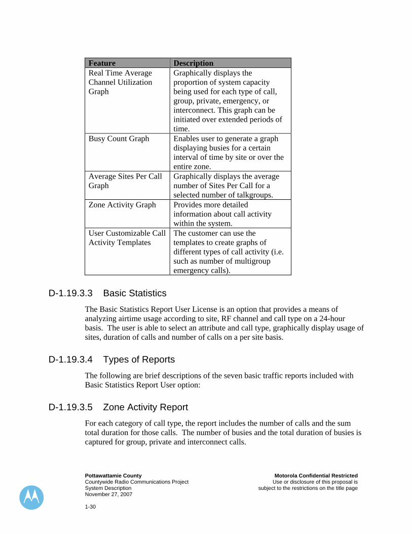
D-1.19.3.2 System Utilization Window The ZoneWatch Utilization window displays and graphs a flexible range of real time traffic behaviors. This capability is a customizable and is a powerful performance management tool.
Pottawattamie County Motorola Confidential Restricted Countywide Radio Communications Project Use or disclosure of this proposal is System Description subject to the restrictions on the title page November 27, 2007 1-30
Feature Description Real Time Average Channel Utilization Graph
Graphically displays the proportion of system capacity being used for each type of call, group, private, emergency, or interconnect. This graph can be initiated over extended periods of time.
Busy Count Graph Enables user to generate a graph displaying busies for a certain interval of time by site or over the entire zone.
Average Sites Per Call Graph
Graphically displays the average number of Sites Per Call for a selected number of talkgroups.
Zone Activity Graph Provides more detailed information about call activity within the system.
User Customizable Call Activity Templates
The customer can use the templates to create graphs of different types of call activity (i.e. such as number of multigroup emergency calls).
D-1.19.3.3 Basic Statistics The Basic Statistics Report User License is an option that provides a means of analyzing airtime usage according to site, RF channel and call type on a 24-hour basis. The user is able to select an attribute and call type, graphically display usage of sites, duration of calls and number of calls on a per site basis.
D-1.19.3.4 Types of Reports The following are brief descriptions of the seven basic traffic reports included with Basic Statistics Report User option:
D-1.19.3.5 Zone Activity Report For each category of call type, the report includes the number of calls and the sum total duration for those calls. The number of busies and the total duration of busies is captured for group, private and interconnect calls.
Motorola Confidential Restricted Pottawattamie County Use or disclosure of this proposal is Countywide Radio Communications Project subject to the restrictions on the title page System Description November 27, 2007 1-31
D-1.19.3.6 Channel Activity Report The Channel Activity Report provides a summary of air-traffic statistics for each channel in the system. Information is provided for the three call types of group, private, and interconnect calls, as well as for emergency messages.
D-1.19.3.7 Group Activity Report The Group Activity Report provides information on all talkgroups. The information provided for each talkgroup is:
♦ Number of group calls ♦ Total group call duration ♦ Number of group busies ♦ Total group busy duration ♦ Number of emergency calls ♦ Total emergency call duration ♦ Number of emergency busies ♦ Total emergency busy duration ♦ Total number of both group and emergency call busies added together ♦ Total duration of both group and emergency call busies added together
D-1.19.3.8 Transaction Summary Report The Transaction Summary Report provides information about the number of Emergency Alarms, Call Alerts, Status/Messages, and Change Me requests that occur on the control channel.
D-1.19.4 Accounting Management Accounting Management pertains to reporting the on-air activity of radio users that can be compiled into reports.
D-1.19.5 Security Management When many different agencies share a communication system, control of their radios and their user’s capabilities is of utmost concern. The System Manager can segment (or partition) access to information in the centralized database according to different user organizations or user categories.
These categories include:
Pottawattamie County Motorola Confidential Restricted Countywide Radio Communications Project Use or disclosure of this proposal is System Description subject to the restrictions on the title page November 27, 2007 1-32
♦ By department ♦ By agency ♦ By geography ♦ By manager user type (e.g.; technician versus service manager) ♦ By application (e.g., ZoneWatch versus Radio Control Manager) ♦ By function within an application (e.g., read-only versus write privileges).
Within the system, every configurable item, such as radios and talkgroups, will be assigned to a Security Group. The configuration items can be assigned to different Security Groups in order to give control over these items to different Zone Manager and UCS users. Each Zone Manager and UCS user is given access to information based on the Security Groups in the system to which he/she has been assigned. Manager users may only access information on subscriber and infrastructure objects that are in Security Groups to which they have been granted access.
D-1.19.6 Radio Control Management The Radio Control Management (RCM) application provides the ability to access the various dispatch commands (such as Dynamic Regrouping, Selective Radio Inhibit, etc.). RCM also allows for receiving emergency calls at a separate location other then the dispatch console.
D-1.20 Over-the-Air Rekeying (Optional not included) The system will have the capability to support Over-The-Air-Rekeying as a future enhancement Over-The-Air-Rekeying (OTAR) provides customers with the ability to rekey portables and mobiles remotely over the RF channel. The rekeying is done by the Key Management Facility (KMF), which formulates and originates the OTAR messages and acts as the key manager of the system. OTAR delivers new keys encrypted with “old” existing keys in radios. OTAR provides several benefits; (1) greatly improves customer productivity by reducing the manpower and time in the field to manually rekey radio users; (2) reduces key management resources by offering an advanced key management solution that will allow customers to plan, generate, store, track and maintain all encryption keys for their entire system using one centralized device rather than tracking everything on paper; and (3) enhances the security of a customer’s encrypted system by allowing customers the ability to frequently change their encryption keys frequently by eliminating security leaks. Secure customers that operate on an encrypted ASTRO 25 (9600) Integrated Voice and Data Trunked System with OTAR are able to deliver new encryption keys “over the RF channel” to the following encrypted subscribers: XTS portable and XTL mobile subscriber equipment.
Motorola Confidential Restricted Pottawattamie County Use or disclosure of this proposal is Countywide Radio Communications Project subject to the restrictions on the title page System Description November 27, 2007 1-33
D-1.21 Key Management Facility (KMF) (Optional not included) The Key Management Facility (KMF) is the key management controller for the P25 Over-The-Air-Rekeying (OTAR) system. The KMF enables effective planning, implementation, and execution of security doctrine for a diverse set of user requirements. The KMF is comprised of three system elements: (1) a software application; (2) Windows 2000 Client/Server Computer and (3) A Crypto Card (CC).
D-1.22 Centralized Key Management (Optional not included) Centralized Key Management, Motorola’s centralized key management solution, allows the customer to manage all of their encryption keys for each secure device within their system using one centralized key management device (Key Management Facility – KMF). The KMF is the management center for the ASTRO P25 OTAR (over-the-air rekeying) system. This product serves two basic functions, key management for the system and the formulation of OTAR messages sent to the subscriber units. All encryption keys for the entire system are stored in the KMF.
D-1.23 Key Loader–KVL 3000 Plus The KVL 3000 Plus is used to create, store and transfer encryption keys used by Motorola’s secure products. The key loader acts as an enabler for all of Motorola’s Secure Communications equipment by supplying the “encryption keys” needed to perform encrypt and decrypt operations. Once two or more devices have been given keys by the key loader, they can then communicate over a secure (encrypted) link.
D-1.24 Dispatch Console Systems
D-1.24.1 Pottawattamie County Backup Dispatch Console Configuration The existing Motorola CENTRACOM Gold Elite console will be upgraded to interface into the ASTRO®25 network. New industry standard PC’s with touch screen flat panel LCDs are quoted as part of this upgrade. The upgrade to the existing CENTRACOM Gold Elite also includes an upgrade to the Microsoft Windows operating system.
Pottawattamie County Motorola Confidential Restricted Countywide Radio Communications Project Use or disclosure of this proposal is System Description subject to the restrictions on the title page November 27, 2007 1-34
D-1.24.2 Operator Positions Motorola is offering an upgrade to your existing CENTRACOM Gold Elite console system. The upgrade includes four (4) of the existing Pottawattamie County console system at the existing Pottawattamie County Dispatch Center. The remote operator at the Fire House will be decommissioned.
The CENTRACOM Elite operates under client-server architecture. This means that all dispatch positions are connected together via a local area network (LAN). In ASTRO®25 systems, the Elite LAN must be connected to the ASTRO®25 wide-area network (WAN).
D-1.24.3 Central Electronics Bank The Central Electronics Bank (CEB) interfaces directly to the ASTRO®25 Ambassador Electronics Bank (AEB) at the Master Site.
For redundancy and reliability, the CEBs will be equipped with redundant Ambassador Interface Multiplex Interface (AIMI) boards that connect to the Ambassador Boards (AMB) in the AEB over redundant T1 Links. The CEB power supplies will also be replaced with new supplies capable of 30 minutes runtime upon the loss of AC power. Seven (7) of the existing BIMs will be refreshed with new software and upgraded to include an ACIM interface. These BIMs will be configured to interface the four (4) XTL5000 consolettes with the CEB. The remaining BIMs and COIMs will also be upgraded with new software.
D-1.24.4 Trunked and Conventional Logging Interfaces Eight (8) trunked talkgroup logging recorder outputs are provided in this upgrade for the existing CEB at the existing Pottawattamie County Dispatch Center. This will be accomplished by adding a Logging Operator Module Interface (LOMI) and associated Audio Expansion Interface (AEI) and a Logging Operator Recording Interface (LORI). The LORI board will occupy a slot in the new CEB card-cage and connect to standard punch down blocks (66 blocks).
The Logging Operator Module Interface (LOMI) de-trunks the system activity by specific talkgroups and provides an individual output for each. This allows individual trunked talkgroups to be interfaced to individual channels on logging recorders. Audio Expansion Interface (AEI) boards receive the audio from the LOMI and send them to the Logging Operator Recording Interface (LORI). The LORI board takes the audio, transforms the impedance to 600Ω then sends it to a punch block.
The select audio at each operator position can also be recorded individually. The output is available on each of the existing CIEs (Console Interface Electronics). Each conventional channel also has a logging recorder output. The 600Ω output is
Motorola Confidential Restricted Pottawattamie County Use or disclosure of this proposal is Countywide Radio Communications Project subject to the restrictions on the title page System Description November 27, 2007 1-35
available at the interface panel for the BIMs (Base Interface Modules). Each conventional channel is interfaced through a BIM to the CEB.
D-1.24.5 Ambassador Electronics Bank The Ambassador Electronics Bank (AEB) is the heart of the ASTRO®25 trunked console system. The AEB is co-located with the Zone Controller at the Master Site. The AEB interfaces directly with the Zone Controller, the CEBs, and the MGEGs.
Pottawattamie County will occupy two slots in the Master Site AEB with two AMB boards.
D-1.25 Console System General Overview The existing Motorola CENTRACOM Gold Elite at the County’s Dispatch center will be upgraded to interface with the ASTRO®25 network. The Gold Elite console system directly controls the ASTRO Project 25 Digital network, as well as interfacing to the existing conventional systems.
D-1.25.1 Console System Furniture No console system furniture is provided.
D-1.25.2 Logging Recorder No Central Logging System is provided for the backup dispatch center.
D-1.25.3 Instant Recall Recorder A new Instant Recall Recorder is provided with each new dispatch computer.
D-1.25.4 Integration to the ASTRO®25 Network The ASTRO®25 Network utilizes a high capacity audio processing switch called the Ambassador Electronics Bank (AEB) which routes audio between radio resources, telephone resources, and dispatchers. This switch, or AEB, is a time division multiplexed digital audio switch that is capable of processing over 700 audio sources with the addition of required hardware. The audio interface to the AEB is via T1 circuits. For ASTRO®25 systems, the AEB processes the console system audio, receiving its control information from the Zone Controller and from the console Central Electronics Banks.
Pottawattamie County Motorola Confidential Restricted Countywide Radio Communications Project Use or disclosure of this proposal is System Description subject to the restrictions on the title page November 27, 2007 1-36
The existing CENTRACOM Gold Series Central Electronics Bank will interface other audio sources into the ASTRO®25 Network.
These sources include and are limited to:
♦ Seven (7) Dispatch Operator Positions ♦ Four (4) 16 I/O cards for legacy system comparator display ♦ One (1) Paging Interface for Fire Paging ♦ Two (2) Conventional Interfaces for 800 MHz Mutual Aid
* Thirteen (13) Conventional Base Stations for interoperability ♦ Seven (7) Backup Trunked Control Stations ♦ One (1) 800 MHz Mutual Aid monitor receiver ♦ Eight (8) Trunked Talkgroup Audio Outputs to an existing logging recorder
This creates a true integrated network, providing users with access to any of the system resources or communication paths.
D-1.25.5 Central Electronics Bank (Upgrade to Existing CEB) A CEB is essentially an intercommunications network that when properly configured, allows for integration of operator positions and the communications equipment they control. The various control cards populated in the CEB, and interfaced to the ASTRO®25 Ambassador Electronics Bank, provide a distributed intelligence network. Within the CEB, all audio is processed in a bi-directional manner between operators and Fixed Network Equipment (FNE).
In the unlikely event of a total failure of an individual CEB, other CEBs and associated console positions will retain full operation and system access.
Due to the multi-processor design of the CEB, the control intelligence of the console system is distributed among all of the dispatcher electronics. Each of the Operator Interfaces in the CEB has all of the processor capability and memory required to operate the console with or without the other dispatcher positions.
If a location requires more audio sources to be supported, such as additional Operator positions, or base/receiver interfaces, additional CEBs are simply placed at that location. Multiple Central Electronics Banks (CEBs) can be connected together allowing any dispatch position access to all the resources in all CEBs. If a large number of Operator positions are required at a single location, multiple CEBs are used to support whatever number of Operators are needed, and all Operators may access the others resources.
This ability to access resources between CEBs also can be used to provide back-up dispatching, access and interoperability to/from different agency’s resources and
Motorola Confidential Restricted Pottawattamie County Use or disclosure of this proposal is Countywide Radio Communications Project subject to the restrictions on the title page System Description November 27, 2007 1-37
systems. The Pottawattamie County system is currently quoted with an upgrade to the existing single CEB in place at the dispatch center.
D-1.25.6 Console Fault Tolerance & Redundancy
D-1.25.6.1 Diagnostics Should a failure occur, CENTRACOM Gold Elite is capable of self-diagnostics and healing, while ensuring fault minimization. To provide this, the CEB is continuously testing the audio & data paths and the microprocessors without the dispatcher’s involvement. Fault detection takes place on a majority rule decision process. Multiple processors can run multiple diagnostic tests on the system. A majority of them must concur that the component has failed before it is taken off line. This provides enhanced levels of redundancy and reliability.
D-1.25.6.2 Automatic Fall Back Once a fault is detected, the CENTRACOM Gold Elite system will automatically switch to a back-up piece of hardware, or try to re-start the failed component in case of a momentary hang up or glitch. If the failed component will not restart and does not contain a backup, then it will be functionally removed from the rest of the system. At the same time an error message will be sent to the affected dispatch position as well as to the MOSCAD terminal for maintenance personnel. This will keep the system working at the highest level of operation possible.
D-1.26 Console System Operator Positions
D-1.26.1 General Four of the existing CENTRACOM Elite console dispatch operator positions will be equipped with a new Pentium PC with Ethernet adapter, CD-ROM, hard drive, mouse, keyboard and touch-screen flat panel LCD monitor. The existing Console Interface Electronics (CIE) and accessories will be reused. The picture below portrays the desktop electronics for each dispatch console position.
Pottawattamie County Motorola Confidential Restricted Countywide Radio Communications Project Use or disclosure of this proposal is System Description subject to the restrictions on the title page November 27, 2007 1-38
The existing CIE includes the Select and Unselect speakers. The Selected speaker provides the dispatcher with audio from the selected channel, while the unselected speaker combines the audio from all of the unselected channels. There is currently no provision for additional Monitor Speakers. If monitor speakers are required, additional system configuration at an additional cost is required that includes adding an additional CEB, two (2) additional T-1 circuits for connectivity and additional interface cards at the Master Site.
The existing hardware options to the Console Interface Electronics will be reused. These may include the following:
♦ Footswitch ♦ Gooseneck Microphone ♦ Headsets ♦ Headset Jack ♦ Second Headset Jack
D-1.27 LAN Configuration The CENTRACOM Elite Console system consists of dispatch operator positions connected to Central Electronics Banks (CEBs). In an Elite system, the CPU’s used for the dispatcher positions are networked, or interconnected with an Ethernet Local Area Network (LAN).
The CENTRACOM Elite operates under client-server architecture. This means that all dispatch positions are connected together via a local area network (LAN). In ASTRO®25 systems, the Elite LAN is connected to the ASTRO®25 wide-area
Motorola Confidential Restricted Pottawattamie County Use or disclosure of this proposal is Countywide Radio Communications Project subject to the restrictions on the title page System Description November 27, 2007 1-39
network (WAN). The Elite Server (CDM Server) is located at the Master Site and is accessed using a remote access software program from the Management Terminal.
D-1.28 Console Database Manager (CDM) The CDM server holds the master database for the console system. This database is used to generate the personality of each dispatch operator position in the system.
The CDM allows field personnel to define and configure the operator positions, conventional channels, and talkgroups which are licensed to a customer, via an easy to use graphical user interface. The system configuration information entered is automatically disseminated to Elite operator positions through the operator, local area network.
Screen configurations may be created by the supervisor and stored on the server. Dispatchers may then access the different configurations over the local area network. This provides convenience by keeping all of the configurations in one place and making updates easier. The configurations may be password protected to ensure proper use. Once the desired screen configuration has been downloaded from the server to a particular operator position, it will run locally and independent from the local area network and server. This means that even if the server or LAN goes down temporarily, dispatching and radio/telephone communication should not be affected. Software upgrades are quoted to upgrade the CDM. The CDM application runs on an existing server located at the OPPD ECC and will be remotely accessed over the ASTRO®25 LAN.
D-1.29 Alias Database Manager The Alias Database Manager (ADM) is another software program of the CENTRACOM Gold Elite console. The ADM extends the overall flexibility of the Control Center by allowing on-line aliasing of two-way radio unit IDs. The ADM allows 14 character aliases to be entered.
In the ASTRO®25 network, entries for unit aliases are only required to be entered once at the network level. Alias names and ID’s are then downloaded to the dispatch console systems saving operator entry time and insuring that names are easily kept up to date. Software upgrades are quoted to upgrade the ADM. The ADM application runs on any dispatch console position and accesses the database over the ASTRO®25 LAN.
Pottawattamie County Motorola Confidential Restricted Countywide Radio Communications Project Use or disclosure of this proposal is System Description subject to the restrictions on the title page November 27, 2007 1-40
D-1.30 Elite Dispatch Program CENTRACOM Gold Elite’s Graphical User Interface makes extensive use of easy to understand Icons to represent functions and features. Multiple screen configurations are quickly and easily accessed through a unique “file folder” concept.
The Elite GUI dispatch area displays the resources being monitored by that particular operator position. Radio resources and auxiliary input/outputs may be integrated on the same screen. Software upgrades are quoted to upgrade the Elite Dispatch. The Elite Dispatch application can be run on any dispatch position for local configuration of the dispatch screens.
D-1.31 Multi-Select and Patch The Multi-Select and Patch groups are stored in "mini-folders". Similar to the "main" folders, the dispatcher can simply click on the tab of one of the Patch or Multi-Select folders to bring that folder forward. In addition to the standard patch, up to 16 resources can be added to a Permanent Patch allows fully automatic enabling and disabling of the patch functions.
D-1.32 Paging Elite paging uses three methods of operation: Quick Page, Standard List Page and Manual Page. Quick Page refers to a one-button press pre-programmed page. The Quick Page is represented on Elite as a resource tile, with a look similar to an Elite Aux I/O resource tile. When the button on the Quick Page resource is pushed, the channel and frequency are automatically selected based on customer specific pre-programmed information. The pre-programmed page (or pre-programmed group page) is sent immediately. Up to 50 pages can be grouped together in a pre-programmed group page. The QuickPage button is identified with an alphanumeric pager icon, but should not be confused with alphanumeric paging. Elite paging is strictly tone-only and tone-and-voice paging except for call alert paging.
Standard List Page and Manual Page folders do not reside on the Elite dispatch screen like Quick Page, but rather reside in a separate stand-alone window. The “Standard Page” window may be opened from the menu bar or from a toolbar button. With the Standard Page window open, the Standard List Page is brought forward using a folder type tab. This folder displays lists of pre-programmed pages and groups. Depending on programming, two lists may be available; either a “Master” list of all pages and groups programmed into the system, or a “Custom” administrator-defined subset of the pages and groups may be displayed. The dispatcher may then choose one or more pre-programmed pages and/or pre-programmed groups to be sent. After selecting the pages and groups, the dispatcher may press the send button to send the pages.
Motorola Confidential Restricted Pottawattamie County Use or disclosure of this proposal is Countywide Radio Communications Project subject to the restrictions on the title page System Description November 27, 2007 1-41
Manual Page is the second folder in the Standard Page window. A Manual Page tab on the dialog box brings up the Manual Page function and keypad. One or more manual pages may be entered and then sent using the send button. A “group” refers to a pre-defined, pre-programmed collection of individual pages.
Pre-programmed Pages and Groups are created and modified using the Alias Database Manager (ADM). The ADM is a separate software application that may be run from any Windows 2000 or Xp computer on the Elite network. Access to the ADM is controlled by access rights assigned by the customer’s Windows 2000 system administrator. The ADM uses a central database that resides on the Elite Server computer. The ADM database may be accessed from one or from multiple points in the system as determined by the system administrator.
The Elite ADM can contain up to a total of 10,000 Unit, and Paging alias entries. The aliases need only be entered once into the ADM database. These aliases are maintained in the centralized ADM database and distributed to the Elite operator positions via the Local Area Network.
Pages can be sent on multiple channels simultaneously or sequentially, depending on the console programming/configuration. Once a page send is initiated but prior to completion of the page, the page may be aborted. An abort button is made available on all 3 paging interfaces.
A visible indication will be given when each individual page ends. The paging tones will be heard in the speaker for the channels that are sending the pages. After the last page ends, there is a talk extend time during which the dispatcher may initiate a voice transmission using the general transmit button or the footswitch. (Note: The general transmit button or footswitch may be pressed at any time after the first page begins.)
The visible indication of a page which failed will remain on the screen for a fixed period of time after the last page ends. Pressing the send button again during that time period will re-send the failed pages. The base station(s) will remain keyed from zero to seven seconds (programmable from the Console Database Manager (CDM)) so that the dispatcher can initiate a voice message without a break in the radio transmission. This is called Page Extend Talk Time.
The paging encoder is capable of being programmed to send the following paging formats:
♦ Call Alert ♦ Quick Call I ♦ Quick Call II: ♦ B - Tone and Voice ♦ C - Tone Only ♦ D - Battery Saver
Pottawattamie County Motorola Confidential Restricted Countywide Radio Communications Project Use or disclosure of this proposal is System Description subject to the restrictions on the title page November 27, 2007 1-42
♦ E - Competitive ♦ Digital Dial 1-3: ♦ Digital Dial 1 = 1500Hz ♦ Digital Dial 2 = 2805Hz ♦ Digital Dial 3 = 1500Hz + 2805Hz ♦ Touch Code (DTMF) ♦ Single Tone ♦ 5/6 Tone
D-1.33 RAVEN Switch The dispatch console systems will be further enhanced with the RAVEN VOX interface. This interface provides a controlled environment to interface tone controlled conventional base stations or trunked control stations to the dispatch console. Audio timing is critical to achieve dependable communications on a conventional channel interface. The Raven provides control over vital audio delay functions and key signaling parameters to ensure proper delivery of analog audio at specific points in the communications network. This is especially important when channels are patched or the dispatcher is using a control station. The Raven card cage houses multiple VOX modules that interface to various conventional channels.
D-1.34 MCC 7500 Dispatch Console System Design The MCC 7500 console site consists of a collection of MCC 7500 dispatch consoles and MCC 7500 Archiving Interface Servers (AISs) and related equipment networked together from a common location.
There are two software programs that comprise the MCC 7500 - the Elite Dispatch graphical user interface (the dispatching software used to operate the dispatch position) and the Elite Admin application (the administrative software used to define the layout of the Elite dispatch screens).
D-1.34.1 Architecture There are three main components of a Motorola MCC 7500 system:
Various combinations of these components are connected together and to the rest of the ASTRO 25 system via console site routers and switches on an IP network.
Motorola Confidential Restricted Pottawattamie County Use or disclosure of this proposal is Countywide Radio Communications Project subject to the restrictions on the title page System Description November 27, 2007 1-43
The dispatch console software consists of the Elite Dispatch graphical user interface (GUI), described in section D-1.34.2 of this system description. The dispatch console hardware is based on a commercially available personal computer with Motorola provided hardware and software.
The Motorola provided hardware includes (refer to Figure 1-3:):
♦ A Motorola-certified personal computer with: • A voice card installed inside the computer
• An optional Secure Card installed inside the computer
♦ A general purpose input/output module (GPIOM)
♦ Desktop speakers (up to 4)
♦ Headset jacks (up to 2)
♦ A desktop microphone
♦ A footswitch
The GPIOM connects to the voice card and performs the digital-to-analog and analog-to-digital conversions for all analog audio flowing into or out of the dispatch console. It also provides the connections for items such as the speakers, headset jacks, microphone, footswitch, local logging recorder, 911 telephone headset, and instant recall recorder for radio.
The voice card provides the vocoding and audio processing services for the dispatch console. It is capable of supporting IMBE vocoder algorithms for ASTRO 25
Pottawattamie County Motorola Confidential Restricted Countywide Radio Communications Project Use or disclosure of this proposal is System Description subject to the restrictions on the title page November 27, 2007 1-44
operation, as well as supporting audio level adjustments, summing, and filtering, and can support multiple simultaneous streams of audio.
The optional Secure Card provides the encryption and decryption services for the dispatch console. It is capable of supporting multiple, simultaneous encryption/decryption sessions using multiple algorithms and multiple secure keys.
The Archiving Interface Server (AIS) provides flexible, high-quality archiving services for audio and data associated with various types of calls and events associated with radio resources. The AIS is a server which allows an IP-based logging recorder to “log onto” the radio system and request talkgroup and conventional channel audio be directed to it for recording. Once configured by the logging recorder, the AIS sends the audio and any information associated with the call (PTT ID, Alias, Type of Call, etc.) to the recorder.
The Conventional Channel Gateway (CCGW) is used in the MCC 7500 Dispatch Console to connect the dispatchers to analog conventional channels in their system. The CCGW allows an analog conventional channel to connect to the transport network in the ASTRO 25 Trunking system. Once these channels are connected to the network, dispatchers are able to monitor and transmit on the channel.
D-1.34.2 Elite Dispatch Graphical User Interface The Motorola MCC 7500 dispatch console uses the Elite Dispatch graphical user interface (GUI) for displaying information to and accepting commands from the dispatcher. The Elite Dispatch GUI is efficient, easy to use, and intuitive, having been refined and proven through years of use in public safety dispatch centers around the world.
An example of the Elite Dispatch GUI is shown in Figure 1-4: .
Motorola Confidential Restricted Pottawattamie County Use or disclosure of this proposal is Countywide Radio Communications Project subject to the restrictions on the title page System Description November 27, 2007 1-45
Tool Bars
ResourceFolders
Patch &Multi-Select
Folders
Activity LogWindow
Status Bar
AuxiliaryInputs/Outputs
RadioResource
RadioResource
RadioResources
RadioResources
Figure 1-4: Elite Dispatch GUI
The Elite Dispatch GUI is based on Microsoft Windows GUI programming standards and contains many controls, displays, and features which are familiar to anyone who has used Windows-based applications. These features are described in greater detail in the following sections.
D-1.34.2.1 Pull Down Menus The dispatcher is able to access features and functions through the pull down menus. The Elite Dispatch GUI provides the following pull down menus on a menu bar across the top of the dispatch window:
♦ Configuration - Provides access to the configuration files used by the Elite Dispatch GUI. Also allows the dispatch application to be exited.
♦ Edit - Allows various aspects of how audio, resources, and features are presented to the user on the Elite Dispatch GUI to be edited. Changes made using this menu are not permanent and are lost when the dispatch application is exited.
♦ View - Allows the dispatcher to control whether or not the Activity Log and Auxiliary I/O Windows are shown.
♦ Folders - Allows the dispatcher to switch between folders, add folders, and change the folder tab width. Changes made using this menu are not permanent and are lost when the dispatch application is exited.
♦ Help - Provides access to detailed online help for using the Elite Dispatch GUI.
Pottawattamie County Motorola Confidential Restricted Countywide Radio Communications Project Use or disclosure of this proposal is System Description subject to the restrictions on the title page November 27, 2007 1-46
The user may customize which menus are displayed and what they contain via the Elite Admin application.
D-1.34.2.2 Tool Bars The toolbar is a row of icon buttons located at the top of the dispatch window. Up to two tool bars may be present, and may be used to provide quick access to frequently used features. The following are examples of the items which may be placed in the tool bars:
♦ Clock ♦ General Transmit Button ♦ Monitor Button ♦ All Mute Button
There are many other items which may be placed in the tool bars. The Elite Admin application is used to define how many tool bars are displayed and what they contain.
D-1.34.2.3 Status Line A status bar is provided across the bottom of the dispatch window for viewing the status of the dispatch console, as well as various error messages. The most current status or error message is displayed in the status line until cleared by the dispatcher. The dispatcher may scroll through the last 10 statuses/error messages to view them and may clear them by using the Features menu on the menu bar.
D-1.34.2.4 Resource Folders The Elite Dispatch GUI provides up to six resource folders for organizing the various resources (radio resources, auxiliary input/output resources, etc.) that are assigned to the dispatch console. These folders may be given descriptive names to simplify the organization of the resources.
The resources on a folder are displayed when the dispatcher clicks on the folder tab. Resources on folders which are hidden behind the one being displayed continue to operate in a normal manner. Radio resource audio on a hidden folder appears in the appropriate speakers/headsets along with a visual call indication on the folder tab. If an emergency alarm or call is received on a radio resource which is located on a hidden folder, a visual emergency indication is displayed on the folder tab.
A resource may be placed on more than one folder at the same time. This allows the customer to create folders for special situations without having to move resources back and forth between folders.
Motorola Confidential Restricted Pottawattamie County Use or disclosure of this proposal is Countywide Radio Communications Project subject to the restrictions on the title page System Description November 27, 2007 1-47
The Elite Admin application is used to configure how many folders appear on the Elite Dispatch GUI and which resources appear on each folder. It is also used to put descriptive names on the folder tabs.
During dispatch operations the dispatcher may, if so configured by the Elite Admin application, be able to add, remove, or move resources on the folders. If this is done, these changes are not saved if the user logs out of or changes configuration files for the dispatch application.
D-1.34.2.5 Radio Resources Voice communication paths in the radio system are represented as radio resources – also referred to as tiles – on the Elite Dispatch GUI. These radio resources are used by the dispatcher to communicate on and control the radio system.
The following radio resources are supported:
♦ Trunked Talkgroups ♦ Trunked Announcement Groups ♦ Trunked Private Calls ♦ Analog Conventional Channels
Indicators and Controls
A radio resource contains indicators and controls that allow the dispatcher to monitor and control various aspects of the radio channel. Examples of the indicators and controls which may appear on a radio resource include:
♦ Instant Transmit Button
♦ Transmit Active/Transmit Busy Indications
♦ Patch Active/Patch Busy Indications
♦ Received Call Indication
♦ Received Call Stack
♦ Individual Volume Control
The types of indicators and controls which appear on the radio resource depend on the type of radio channel it represents, and how it has been configured in the Elite Admin application. The radio resource may be configured as a compressed resource, a larger compressed resource, or an expanded resource.
♦ Compressed Resource – Allows the dispatcher to hide the indicators and controls of the radio resource (Figure 1-5: ). The small arrow button opens and closes the resource to show the controls and indicators. This saves a tremendous amount of space on the screen by allowing the dispatcher to view only the most critical information for any given channel. This type of display is ideal for dispatchers
Pottawattamie County Motorola Confidential Restricted Countywide Radio Communications Project Use or disclosure of this proposal is System Description subject to the restrictions on the title page November 27, 2007 1-48
monitoring several different channels where space in the resource folder is at a premium.
Flap OpenFlap Closed
Figure 1-5: Compressed Radio Resource
♦ Larger Compressed Resource –A radio resource that always shows some of the indicators and controls, but allows the dispatch console to hide some of the others (Figure 1-6: ).
Flap OpenFlap Closed
Figure 1-6: Larger Compressed Radio Resource
♦ Expanded Resource –This radio resource always shows the indicators and controls (Figure 1-7: ), and cannot be compressed. The expanded version provides the advantage of a single-button press for any function. It is ideal for dispatchers who are only monitoring a few channels/talk groups and where space in the resource folder is not at a premium.
Motorola Confidential Restricted Pottawattamie County Use or disclosure of this proposal is Countywide Radio Communications Project subject to the restrictions on the title page System Description November 27, 2007 1-49
Figure 1-7: Expanded Radio Resource
Any activity or change on a radio resource appears on all dispatch consoles that have that resource assigned on them.
Received Call Stack
The received call stack provides the dispatcher with a visual record of the most recent inbound calls on radio resources. This allows the dispatcher to keep track of calls during busy traffic periods.
The calls are displayed in list format on a radio resource, with the most recent calls at the top of the list. The number of calls displayed in the list is configurable, as is the type of information displayed. The types of information that can be displayed include unit ID, unit ID alias, site ID, zone ID, type of call, and time. If an alias is available for a piece of information, it is displayed; otherwise the raw information is displayed. Figure 1-8: shows a radio resource containing a received call stack.
ReceivedCall StackReceivedCall Stack
Figure 1-8: Received Call Stack on a Radio Resource
Pottawattamie County Motorola Confidential Restricted Countywide Radio Communications Project Use or disclosure of this proposal is System Description subject to the restrictions on the title page November 27, 2007 1-50
The received call stack has a fixed memory of 25 calls, but the number of calls which are displayed is configurable via the Elite Admin application. Regardless of how many calls are actually displayed, the dispatcher can always scroll through all 25 calls in the stack’s memory.
The dispatcher can delete individual calls from the received call stack. All of the calls listed in a received call stack can also be deleted with a single action.
D-1.34.2.6 Auxiliary Input and Output Resources Auxiliary inputs and outputs (Aux I/Os) allow the system to control external devices via relay closures and sense the state of external devices via input buffers from the MCC 7500 Dispatch Console.
The Aux I/O resources are represented by various graphical icons that change their appearance based on the state of the resource. The Elite Admin application is used to associate a particular icon with a specific input or output. Examples of some of the icons which may be used are shown in Figure 1-9: .
Icon for Input Buffer (shown in Active State)
Icon for Control Relay (shown in Active State)
Icon for Control Relay (shown in Inactive State)
Figure 1-9: Auxiliary Input/Output Resource Icons
If an Aux I/O changes state, the change of state is reflected on all the other dispatch consoles that have the Aux I/O assigned on them.
D-1.34.2.7 Patch and Multi-Select Folders The patch and multi-select features are accessed via a set of dedicated folders on the Elite Dispatch GUI. These folders are smaller than the resource folders, and may be placed on the screen to suit the dispatcher’s preferences. The placement is done in
Motorola Confidential Restricted Pottawattamie County Use or disclosure of this proposal is Countywide Radio Communications Project subject to the restrictions on the title page System Description November 27, 2007 1-51
the Elite Admin application. There can be up to sixteen patch folders and three multi-select folders.
D-1.34.2.8 Patch Folders Clicking on one of the patch folder tabs brings it into view. The patch group is then opened by clicking on the left-most button on the folder. Once the patch group is open, the patch group is editable and members may be added or removed from the patch group by clicking on the desired radio resources. Note that patch groups are active whenever there are members assigned to them. This is true even if the patch group isn’t open.
The members of the patch group are shown on the patch folder along with the status of each member (patched or pending). The resources in the patch also show an indication that they are in a patch group.
Some patch groups contain members which were pre-assigned by the Elite Admin application. These patch groups become active as soon as possible after the dispatch console begins using the configuration file which contains the pre-assigned patch groups. The dispatcher can add/remove members from the pre-assigned patch group, but these additions/removals are lost when the dispatch console either re-loads the configuration file, or changes to a different configuration file.
A patch transmit button is provided on the patch folder to allow the dispatcher to easily transmit on all members of the patch group with a single button press.
Figure 1-10: shows an example of a patch folder containing some radio resources.
Figure 1-10: Patch Folder
Pottawattamie County Motorola Confidential Restricted Countywide Radio Communications Project Use or disclosure of this proposal is System Description subject to the restrictions on the title page November 27, 2007 1-52
Multi-Select Folder
Clicking on one of the multi-select folder tabs brings it into view. The multi-select group is then opened by clicking on the left-most button on the folder. Once the multi-select group is open, the multi-select becomes active, and members can be added or removed from the group by clicking on the desired radio resources. Closing the multi-select folder (by clicking on the left-most button a second time) deactivates the multi-select group.
Note: This operation is different than that of the patch folders. A dispatch console can only have one multi-select group active at a time, but it can have multiple patch groups simultaneously active.
The members of the multi-select group are shown on the multi-select folder.
Some multi-select groups contain members which were pre-assigned by the Elite Admin application. The dispatcher can add/remove members from the pre-assigned multi-select group, but these additions/removals are lost when the dispatch console either re-loads the configuration file or changes to a different configuration file.
Figure 1-11: shows an example of a multi-select folder containing some radio resources.
Figure 1-11: Multi-Select Folder
D-1.34.2.9 Activity Log Window The dispatcher can use the activity log window as a point of reference for all calls coming into the dispatch console. The activity log shows call information associated
Motorola Confidential Restricted Pottawattamie County Use or disclosure of this proposal is Countywide Radio Communications Project subject to the restrictions on the title page System Description November 27, 2007 1-53
with all incoming radio calls including the name of the radio resource and the time of the call. Incoming calls from all radio resources assigned to the dispatch console are displayed in the activity log.
Figure 1-12: shows an example of an activity log window.
Activity LogResourceTile
List of Calls
Figure 1-12: Activity Log Window
Up to 1000 calls can be held in the activity log. The most recent call is on the top of the list and the oldest at the bottom. Once the list is filled, the oldest calls are discarded as new calls come in. The dispatcher may resize the activity log to show various numbers of calls. For example, when there is light activity, the dispatcher may choose to only show a few calls. During busy hours, the dispatcher may view more calls by simply dragging the lower right hand corner of the activity log (making it longer) to see additional calls.
Dispatchers may respond to incoming calls simply by clicking on a call in the list. Once a call is selected, the entry appears highlighted, and the name of the radio resource appears at the top of the activity log. The dispatcher can then press the instant transmit button on the activity log resource tile to communicate with that radio resource.
The information displayed by the activity log can be customized to suit the dispatcher's needs. The activity log can be configured to show combinations of Resource Name, Unit ID or Alias, Status Number or Alias, Receiving Site ID, Receiving Zone ID, and Time. This configuration is done via the Elite Admin application and, if so configured, via the dispatcher interface.
The Elite Admin application controls whether or not a dispatch console has the capability of displaying the activity log. If a dispatch console is given the capability, the dispatcher has the ability to view or not view the activity log based on their needs.
The number of lines that are initially displayed by the activity log is configurable via the Elite Admin application or the dispatcher interface. The number of lines that are displayed may also be changed in real time by changing the size of the activity log
Pottawattamie County Motorola Confidential Restricted Countywide Radio Communications Project Use or disclosure of this proposal is System Description subject to the restrictions on the title page November 27, 2007 1-54
window. The user can scroll through all the entries in the activity log, even if they can’t all be displayed at once.
D-1.34.2.10 Help The dispatch console is designed to allow the dispatcher to quickly access information on how to use its features. There are three types of help available to the dispatcher: Online, Micro and Tool Tips.
Online Help
Online Help provides detailed information on how to use the dispatch console. The user accesses Online Help via the Help menu on the menu bar. The user can search for topics or key words to quickly find the desired information or the user can use a table of contents to find the information. The information is displayed in a pop-up window on the dispatch user interface.
Online Help allows new dispatchers to shorten their learning curve and more experienced dispatchers to quickly remember how to operate seldom-used features.
Micro Help
Micro Help provides information about the state of controls or indicators in a resource tile. When the cursor is placed over a control or indicator on a resource tile, a description of the control or indicator's state is given across the bottom of the resource tile. Figure 1-13: shows micro help text on a radio resource. The text across the bottom of the resource describes the icon the cursor is pointing to.
Micro HelpTextMicro HelpText
Figure 1-13: Micro Help on a Radio Resource
The text displayed by the Micro Help feature may be edited via the Elite Admin application.
Motorola Confidential Restricted Pottawattamie County Use or disclosure of this proposal is Countywide Radio Communications Project subject to the restrictions on the title page System Description November 27, 2007 1-55
Micro Help allows a dispatcher to view the status of a control or indicator textually instead of graphically.
Tool Tips Help
Tool Tips Help provides information about tool bar buttons and menu bar menus to the dispatcher. When the cursor is placed over a tool bar button, the button's name appears in a small pop-up window next to the cursor, and a short explanation of the button appears in the status bar at the bottom of the dispatch user interface window. When the cursor is moved across a menu item in a menu, a description of the menu item appears in the status bar at the bottom of the dispatch user interface window.
The text displayed by the Tool Tips feature may be edited via the Elite Admin application.
Tool Tips allow a dispatcher to quickly see a short explanation of the button or menu item of interest.
D-1.34.3 Elite Admin Application The Elite Dispatch GUI screens are configured using the Elite Admin application. This application is designed to be extremely flexible. It allows the administrator to make the screen look very simple with minimal icons and channels, or more sophisticated with many folders and channels. The Elite Admin application allows supervisors to create screens that can be used by multiple dispatchers (accessed over the network) or even a customized screen per dispatcher. Each screen configuration may be password protected to ensure proper use and control. All of the screen configurations are stored on the server. Once the screens are downloaded to a particular dispatch position, the configuration is run independently from the server and LAN.
Through the Elite Admin application the supervisor can perform functions including:
♦ Create new configurations (for any operator). ♦ Enable or disable operator positions. ♦ Modify existing configurations. ♦ Assign/de-assign radio resources to various folders and determine location. ♦ Determine audio routing of resources to speakers. ♦ Set initial volume level of radio and phone resources. ♦ Determine icons used for AUX I/Os. ♦ Determine if Auxiliary I/Os are safety switch protected, and have an audible
alarm. ♦ Determine items that should go on the toolbar and where they should be placed.
Pottawattamie County Motorola Confidential Restricted Countywide Radio Communications Project Use or disclosure of this proposal is System Description subject to the restrictions on the title page November 27, 2007 1-56
♦ Create pre-assigned patch/multi-select/primary groups ♦ Determine if the activity log is shown initially and where on the screen it is shown
(dispatchers may still hide or show the activity log) ♦ Assign/de-assign radio and auxiliary input/output resources to various folders ♦ Determine where features are placed on each radio resource ♦ Determine the size of each radio resource ( compressed, larger compressed or
expanded)
D-1.34.4 Archiving Interface Server The MCC 7500 Archiving Interface Server (AIS) provides an interface between the radio system and a 3rd party logging recorder. This allows calls on the radio system to be recorded together with information associated with the calls. Certain non-call radio system events (e.g., emergency alarms, changing frequencies on multi-frequency conventional stations, etc.) may also be recorded.
The user can configure the 3rd party recorder to monitor and record a set of radio system resources (trunked or conventional). The AIS monitors the identified resources, passes call-control information to the logging sub-system via an API, and redirects audio for those monitored channels to the logging sub-system via the LAN. The logging recorder then records this information to some storage media.
The logging sub-system provides a user interface capable of allowing a user to identify actions/calls that occurred on the radio system, choose the desired call they wish to review, and play back the audio for that call through a logging playback station. The logging sub-system reconstructs the playback audio from the vocoded samples that had been sent to the logging sub-system when the call occurred.
The recording and playback of system events is restricted to users who have been granted rights to access the information. The radio system's network manager product defines the “agencies” in a given communication system (e.g. Police, Fire, Public Works, etc.), and the logging sub-system follows the agency partitioning rules that are set up by the network manager. This restricts the logging recorders in one agency from recording information that pertains to another agency’s traffic (if so configured).
The AIS is comprised of a personal computer with voice card(s) or Secure Card(s) installed inside of it. Each voice card or Secure Card has a network connection to the trunking system transport network.
Note: At this time, the only 3rd party logging recorder currently available for use with the Archiving Interface Server is the NiceLog® recorder, made by NICE systems. The recorder is not part of this proposal.
Motorola Confidential Restricted Pottawattamie County Use or disclosure of this proposal is Countywide Radio Communications Project subject to the restrictions on the title page System Description November 27, 2007 1-57
D-1.34.4.1 Supported Call Types and Events The following types of radio system calls are capable of being processed via the AIS.
♦ Conventional PTT Call
♦ Trunking Talkgroup Call
♦ Trunking Announcement Group Call
♦ Trunking Emergency Call
The following types of trunking radio system events are capable of being processed via the AIS.
♦ Emergency Alarm
♦ Emergency Acknowledge
♦ Emergency Knockdown
♦ Repeater On/Off
♦ System Access Priority Selection (Tactical/Normal)
The following types of conventional radio system events are capable of being processed via the AIS.
♦ Frequency Selection
♦ Private Line (PL) Selection
♦ Mute Second Receiver
♦ Repeater On/Off
♦ Wildcard I
♦ Wildcard II
D-1.34.5 Conventional Channel Gateway Conventional channels are much more integrated into ASTRO 25 trunking systems than in previous radio systems. The zone controller manages conventional channels in a manner similar to how it manages trunked talkgroups.
The physical interface to the analog conventional stations also changes from previous radio systems. RF site routers or console site routers are fitted with 4 wire interface cards, which are connected to the analog conventional stations. This connection allows the conventional audio to use the same transport network as the trunked audio. The portion of the router hardware and software that support the conventional stations is called the Conventional Channel Gateway (CCGW).
Pottawattamie County Motorola Confidential Restricted Countywide Radio Communications Project Use or disclosure of this proposal is System Description subject to the restrictions on the title page November 27, 2007 1-58
Up to four analog conventional stations may be connected to a router. If the number of stations at a site exceeds the capacity of the router, additional routers can be added to support those stations. This console system is being proposed with 24 conventional (non-Trunked) channel interfaces. Some of these interfaces are reserved for specific functions that will be discussed during the DDR.
D-1.34.5.1 External Paging Encoder Port The External Paging Encoder Port feature allows an external tone paging encoder to be used with a dispatch console to provide tone paging services. The encoder is not included in this proposal. Analog paging tones generated by the encoder are transmitted by the dispatch console on the selected Trunked and/or conventional radio resource(s). The 7.2 release of MCC7500 will allow tone paging from the GUI.
D-1.34.5.2 Types of Conventional Stations Supported The CCGW supports the following types of analog conventional base stations.
♦ R1 ♦ T1R1 ♦ T1R1 w/Paging ♦ T2R2 ♦ T4R4
MCC 7500 Dispatch Consoles
Console Site Link (WAN)
LAN Switch
Console Site Router w/ Conventional IP Interface Kit
1 of 6 CCGWs
MCC 7500 Archiving Interface
Server NICE Logging Recorder (not included)
NICE Playback Station (not included)
n links (n=1or 2)
AnalogConventionalStations
ConventionalSiteController
4 -WireAnalogLines
20 Conventional Channels
Motorola Confidential Restricted Pottawattamie County Use or disclosure of this proposal is Countywide Radio Communications Project subject to the restrictions on the title page System Description November 27, 2007 1-59
♦ T8R8 ♦ T12R12 ♦ T14R14
TnnR channels must be supported using combinations of T1R1 channels.
Pottawattamie County Motorola Confidential Restricted Countywide Radio Communications Project Use or disclosure of this proposal is System Description subject to the restrictions on the title page November 27, 2007 1-60
D-1.35 List of Acronyms AAT – Above Average Terrain
AC – Alternating Current
ACIM – Astro Console Interface Module
ADM – Alias Database Manager
AEB – Ambassador Electronics Bank
AEI – Audio Expansion Interface
AIMI – Ambassador Interface Multiplex Interface
AIS – Archiving Interface Server
Amp - Ampere
AMSL – Above Mean Sea Level
AUDI – Audio Distribution Interface
APCO - Association of Public-Safety Communications Officials
Motorola Confidential Restricted Pottawattamie County Use or disclosure of this proposal is Countywide Radio Communications Project subject to the restrictions on the title page System Description November 27, 2007 1-61
CPU – Central Processing Unit
CWR – Cooperative WAN Router
DAQ – Delivered Audio Quality
DC – Direct Current
Db - Decibel
DES – Digital Encryption Standard
DID – Direct Inward Dial (Telco)
DDR – Detail Design Review
DMZ – Demilitarized Zone
DNS – Domain Name System
DS1 - Digital Signal 1 (see T1)
ECC – Energy Control Center
ERP – Estimated Radiated Power
FDMA – Frequency Division Multiple Access
FNE – Fixed Network Equipment
FSA – Fire Station Alert
GMC – Graphics Master Central (MOSCAD Server) GPIOM – General Purpose Input/Output Module
GPS – Global Positioning System
GUI – Graphical User Interface
GWS – Graphics Work Station (MOSCAD Client)
HPOV – Hewlett Packard Open View (p/o Hp Software Suite)
Pottawattamie County Motorola Confidential Restricted Countywide Radio Communications Project Use or disclosure of this proposal is System Description subject to the restrictions on the title page November 27, 2007 1-62
IP – Internet Protocol
I/O – Input / Output
KHz – Kilohertz
KVL – Key Variable Loader
KVM - Keyboard Video Mouse
LAN – Local Area Network
LCD – Liquid Crystal Display
LED – Light Emitting Diode
LOMI - Logging Operator Module Interface
LSM – Linear Simulcast Modulation
MGEG – Motorola Gold Elite Gateway
Mbps – Megabits per second
mS – Milliseconds
MHz - Megahertz
NAT – Network Address Translation
NM – Network Management (SmartZone)
NFM – Network Fault Management (MOSCAD)
NPSPAC – National Public Safety Planning Advisory Committee
NPPD – Nebraska Public Power District
OFB – Output Feedback
OPPD – Omaha Public Power District
OS – Operating System
P25 – APCO Project 25
PA – Power Amplifier
PC – Personal Computer
PPS – Pulse per Second
PSM – Public Safety Microphone
Motorola Confidential Restricted Pottawattamie County Use or disclosure of this proposal is Countywide Radio Communications Project subject to the restrictions on the title page System Description November 27, 2007 1-63
PSTN – Public Switched Telephone Network
PTT – Push to Talk
RF – Radio Frequency
RFP – Request for Proposal
RNI – Radio Network Infrastructure
RTU – Remote Terminal Unit (MOSCAD remote electronics)
SDK – Software Development Kit
SZ – SmartZone
T1 – T- Carrier Signal 1 (AT&T and Bell Labs standard for digital wire-line communication)
T1R1 – One channel transmit and one channel receive
TCP – Transmission Control Protocol
TDM – Time Division Multiplex
TDMA – Time Division Multiple Access
TELCO – Telephone Company
TeNSr – Telecommunications Network Server (Channel Bank)
TNM – Transport Network Manager (SmartZone)
uS - Microseconds
UCS – User Configuration Server (SmartZone)
UPS – Uninterruptible Power Supply
VAC – Volts Alternating Current
VDC – Volts Direct Current
VOX – Voice Activated
VU – Volume Unit
WAN – Wide Area Network
ZAMBI - Zone Ambassador Interface (Control Centers Product)
ZC – Zone Controller
Pottawattamie County Motorola Confidential Restricted Countywide Radio Communications Project Use or disclosure of this proposal is System Description subject to the restrictions on the title page November 27, 2007 1-64