Exmoor & Dartmoor Electric Range PR2768 Issue 2 (April 2021) Instructions for Use, Installation & Servicing For use in GB & IE (Great Britain & Republic of Ireland). IMPORTANT PARTS OF THE OUTER CASING OF THIS APPLIANCE ARE CONSIDERED BY THE MANUFACTURER TO BE A WORKING SURFACE WHICH BECOMES HOT WHEN THE HEATER IS SWITCHED ON. IT IS THEREFORE RECOMMENDED THAT A FIREGUARD COMPLYING WITH BS 8423 (LATEST EDITION) IS USED IN THE PRESENCE OF YOUNG CHILDREN, THE ELDERLY OR INFIRM. THE HEATER OUTLET GRILLE BECOMES VERY HOT WHILST IN OPERATION. DO NOT COVER THE OUTLET GRILLE OR ANY PART OF THE APPLIANCE. For use with 230V 50Hz electricity supply only. Please read these instructions carefully before installation and keep them in a safe place. They will be needed when maintenance or servicing is required. THIS APPLIANCE MUST BE EARTHED This product is only suitable for well insulated spaces and occasional use.
Transcript
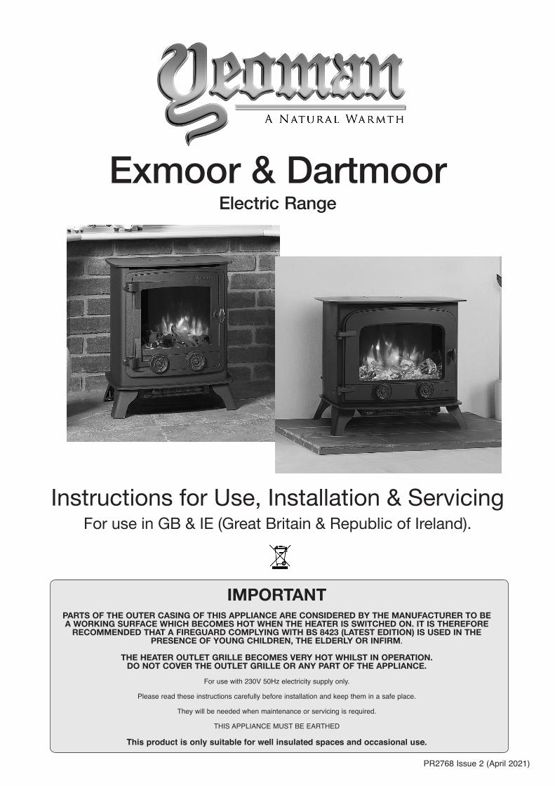
Exmoor & Dartmoor Electric Range
PR2768 Issue 2 (April 2021)
Instructions for Use, Installation & ServicingFor use in GB & IE (Great Britain & Republic of Ireland).
IMPORTANTPARTS OF THE OUTER CASING OF THIS APPLIANCE ARE CONSIDERED BY THE MANUFACTURER TO BE A WORKING SURFACE WHICH BECOMES HOT WHEN THE HEATER IS SWITCHED ON. IT IS THEREFORE
RECOMMENDED THAT A FIREGUARD COMPLYING WITH BS 8423 (LATEST EDITION) IS USED IN THE PRESENCE OF YOUNG CHILDREN, THE ELDERLY OR INFIRM.
THE HEATER OUTLET GRILLE BECOMES VERY HOT WHILST IN OPERATION. DO NOT COVER THE OUTLET GRILLE OR ANY PART OF THE APPLIANCE.
For use with 230V 50Hz electricity supply only.
Please read these instructions carefully before installation and keep them in a safe place.
They will be needed when maintenance or servicing is required.
THIS APPLIANCE MUST BE EARTHED
This product is only suitable for well insulated spaces and occasional use.
2
ContentsCovering the following models:
User Instructions .......................................................3
1. Important Information & Health and Safety ............................ 32. Operating Instructions ............................................................ 43. Maintenance ...........................................................................8
1. General .................................................................................122. Locating the Appliance .........................................................123. Fitting the Appliance .............................................................124. Fuel Effect ............................................................................ 135. Completion of Assembly .......................................................14
1. Fault Finding......................................................................... 152. How to Wire a Plug .............................................................. 153. Servicing Requirements ....................................................... 164. Cast Front & Exterior Glass .................................................165. Removing the LED Light Bar ...............................................176. Removing the Glass Side Panels .......................................177. Removing the Fuel Bed ......................................................188. Removing the Interior Glass Screen ...................................189. Replacing the Fuel Bed Effect Spindle ............................... 1910. Replacing the Fuel Bed LED Boards ................................1911. Removing the Effect Screen ..............................................1912. Replacing the Flame Effect Spindle ..................................2013. Replacing the Flame Effect LED Board ............................ 2014. Replacing the Fuel Bed Motor ..........................................2115. Replacing the Flame Effect Motor .....................................2116. Replacing the Heater Assembly ........................................2217. Replacing the PCB ............................................................2218. Replacing the RF Receiver ...............................................2319. Pairing the Remote Control to the Appliance ..................... 2320. Resetting the Remote ........................................................23
Spare Parts List .......................................................25
Information Requirement - Electric Heaters .........26
To receive your Extended Warranty your Yeoman appliance must have been purchased from our Expert Retailer Network and registered within one month of purchase or installation. Please note that all warranties are effective from the date of purchase. Any Yeoman product purchased outside of our Extended Retailer Network, or not registered within the stated time will carry a standard 12 month warranty.
Full terms and conditions are detailed in the Warranty Statement on the Yeoman website www.yeoman-stoves.co.uk. In the event of any conflict of information the wording on the website shall prevail.
Important Note: Should any problems be experienced with your product, claims must first be submitted to the Expert Retailer where the appliance was purchased from who will offer immediate assistance or contact Yeoman on your behalf.
Registration No WEE/DH1656ZWIn accordance with European Directive 2012/19/EU, waste electrical and electronic equipment (WEEE) must not be disposed of with household waste.
At the end of its useful life please take this product to an appropriate recycling centre or collection point. You can find your nearest recycling centre by using the bank locator atwww.recycle-more.co.uk for UK customers, www.weeeireland.ie for customers in the Republic of Ireland, or by contacting your local authority.
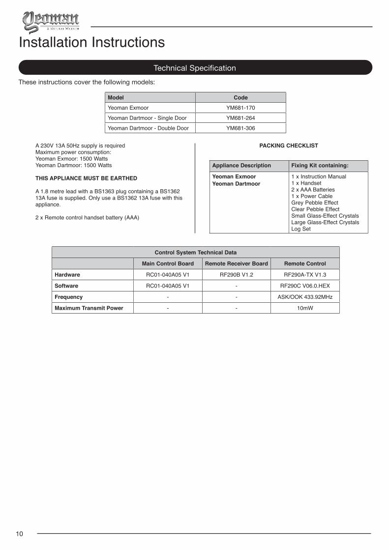
Model Code
Yeoman Exmoor YM681-170
Yeoman Dartmoor - Single Door YM681-264
Yeoman Dartmoor - Double Door YM681-306
3
User Instructions1. Important Information and
Health and Safety
1.1 Read all of the instructions carefully before using the appliance.
1.2 Remove all packaging and dispose of at an appropriate recycling facility.
1.3 Do not locate this appliance immediately below a fixed socket outlet.
1.4 Parts of the outer casing of this appliance are considered by
the manufacturer to be a working surface which becomes hot when the heater is switched on. You must use a suitable fire guard to protect children, the elderly and the infirm.
1.5 Do not use this appliance in the immediate surroundings of a bath, shower, swimming pool or any other area where the appliance could come into contact with water or humidity, e.g. a bathroom.
1.6 WARNING! DO NOT COVER
Do not allow the appliance to be covered or let the air inlet/outlet become obstructed as the appliance may overheat. Please note the warning symbol on the appliance (see above).
1.7 For indoor use only. This appliance is not suitable for use outside the house.
1.8 This appliance must stand on a clean, level, firm surface. Do not stand the fire on a carpet. Ensure that furniture, curtains etc. are positioned no closer than 1m and the fire stands on a surface that can withstand temperatures of 90°C for prolonged periods. Do not allow rugs to be placed within 500mm of the front of the appliance.
1.9 Where the electricity supply cable has to pass through a fire place, stone surround etc. ensure suitable rubber bushes are fitted at possible wear points.
1.10 If installed in an open fireplace, blank off the chimney to reduce the risk of a back draught which can cause the safety cut-out to operate.
1.11 Keep the power cord away from hot surfaces and hot conditions. Do not route the power lead in front of the appliance.
1.12 When the fire has been installed the position of the plug must be accessible.
1.13 If the electricity supply cable is damaged do not use the appliance until it has been replaced. For safety reasons the replacement has to be carried out by a Yeoman service agent or a similarly competent electrician.
1.14 CAUTION: In order to avoid a hazard due to inadvertent resetting of the thermal cut-out, this appliance must not be supplied through an external switching device, such as a timer, or connected to a circuit that is regularly switched on and off by the utility.
1.15 Do not operate the appliance if it is damaged.
1.16 Repairs of electrical appliances must only be performed by an electrical engineer. Should the appliance fail to operate,
or in case of any damage, please contact the retailer from whom the appliance was purchased.
1.17 This appliance can be used by children aged from 8 years and above and persons with reduced physical, sensory or mental capabilities or lack of experience and knowledge if they have been given supervision or instruction concerning use of the appliance in a safe way and understand the hazards involved. Children of less than 3 years should be kept away unless continuously supervised.
Children aged from 3 years and less than 8 years shall only switch on/off the appliance provided that it has been placed or installed in its intended normal operating position and they have been given supervision or instruction concerning use of the appliance in a safe way and understand the hazards involved. Children aged from 3 years and less than 8 years shall not plug in, regulate and clean the appliance or perform maintenance.
However Yeoman recommend:
This appliance is not intended to be used by persons under the age of 12, persons with reduced physical, sensory or mental capabilities or persons with lack of experience and knowledge in the safe operation of the appliance.
The appliance may be operated by persons above the age of 12 provided they have been instructed in the safe use of the appliance and that they understand the hazards involved. Persons above the age of 12 may also operate the appliance under the supervision of a responsible adult.
Parts of this appliance become hot whilst in operation and
under no circumstances should persons under the age of 12 be left alone with the product when it is in operation unless a suitable fireguard is used to protect them against the possibility of coming into direct contact with the appliance.
Children shall not play with the appliance.
Cleaning and user maintenance shall not be made by children without supervision.
4
2. Operating Instructions
WARNING! Do not operate the appliance if it is damaged or has malfunctioned. If you suspect the appliance is damaged or has malfunctioned call a qualified service engineer to inspect the appliance, and replace any part of the electrical system if necessary, before reuse.
Do not disconnect the power at the mains supply whilst the appliance is running. Use the functions on the remote to turn the fire off and ensure the mains switch has been moved to the off position before disconnecting.
GENERAL
2.1 The appliance can be operated by the radio frequency handset or the manual controls which are behind the plinth, see Diagram 1.
NOTE: To use both remote and manual functions the manual on/off switch must be in ‘ON’ position. In order to prevent the product becoming too hot, there is a 10s delay when turning on the heater and a 10s delay when turning off the heater fan.
The manual button controls basic functions, not a full range of controls. Use the remote hand set to carry out all functions.
PREPARATION BEFORE USE
Batteries:
2.2 Ensure that the handset batteries are new and inserted correctly.
2.3 Dispose of old batteries at an appropriate recycling facility.
LOCATION OF POWER SWITCH
2.4 The mains power switch is located on the control panel located on the right-hand side, see Section 2a.
Mains Power Switch
1
2.5 Switch ON (—) before operating either the remote or manual controls.
2.6 A long beep is heard to indicate the fire is ready for use.
2a. Manual Control Panel
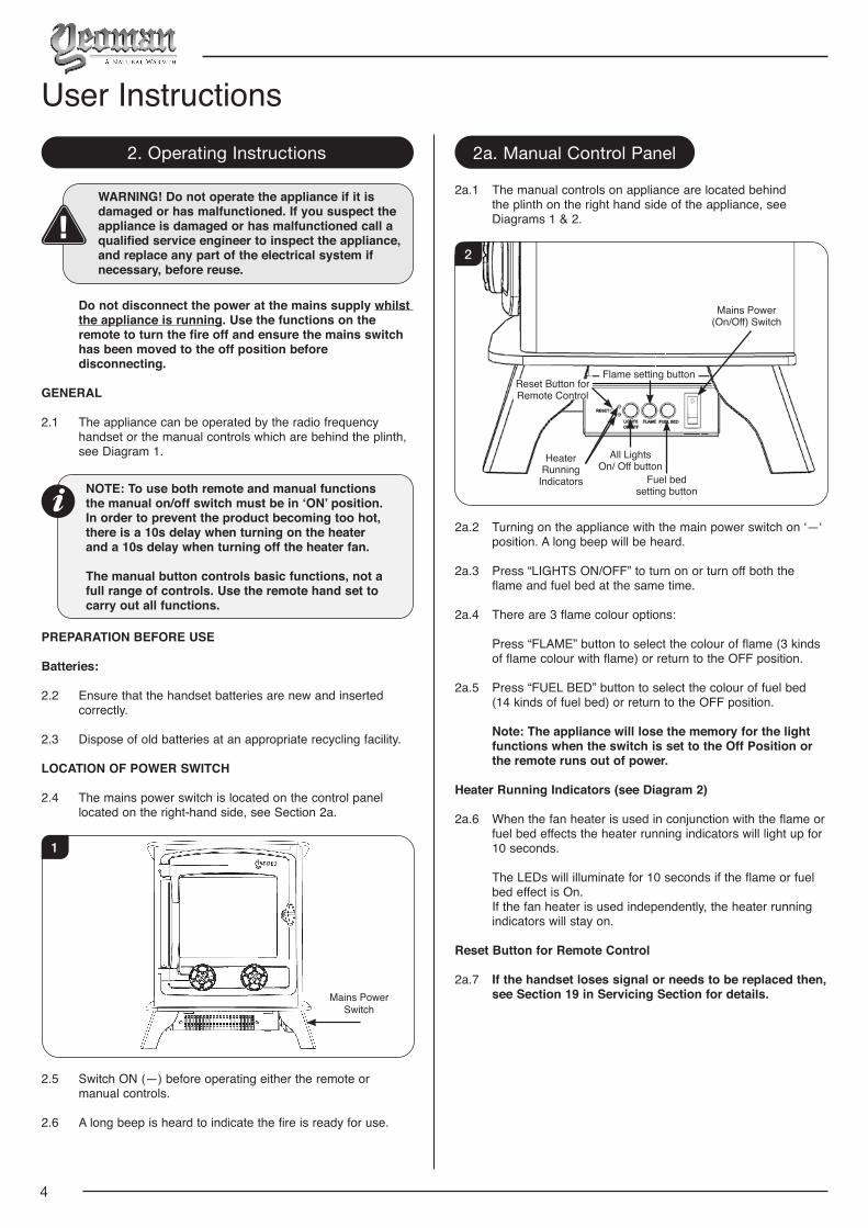
2a.1 The manual controls on appliance are located behind the plinth on the right hand side of the appliance, see Diagrams 1 & 2.
Mains Power(On/Off) Switch
Fuel bed setting button
Flame setting button
All Lights On/ Off button
Reset Button for Remote Control
Heater Running
Indicators
2
2a.2 Turning on the appliance with the main power switch on ‘—‘ position. A long beep will be heard.
2a.3 Press “LIGHTS ON/OFF” to turn on or turn off both the flame and fuel bed at the same time.
2a.4 There are 3 flame colour options:
Press “FLAME” button to select the colour of flame (3 kinds of flame colour with flame) or return to the OFF position.
2a.5 Press “FUEL BED” button to select the colour of fuel bed (14 kinds of fuel bed) or return to the OFF position.
Note: The appliance will lose the memory for the light functions when the switch is set to the Off Position or the remote runs out of power.
Heater Running Indicators (see Diagram 2)
2a.6 When the fan heater is used in conjunction with the flame or fuel bed effects the heater running indicators will light up for 10 seconds.
The LEDs will illuminate for 10 seconds if the flame or fuel bed effect is On.
If the fan heater is used independently, the heater running indicators will stay on.
Reset Button for Remote Control
2a.7 If the handset loses signal or needs to be replaced then, see Section 19 in Servicing Section for details.
User Instructions
5
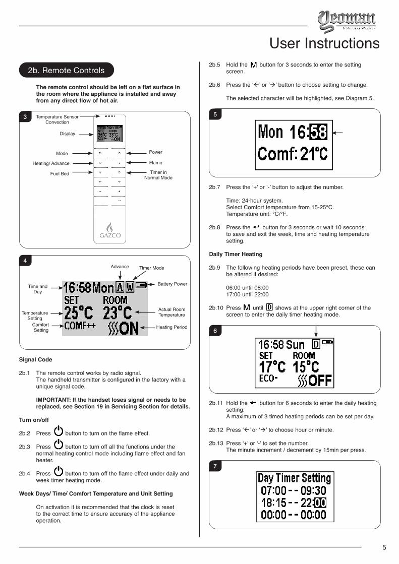
2b. Remote Controls
The remote control should be left on a flat surface in the room where the appliance is installed and away from any direct flow of hot air.
3
Timer in Normal Mode
Flame
Power
Heating/ Advance
Mode
Temperature Sensor Convection
Display
Fuel Bed
4
Heating Period
Battery Power
Actual Room Temperature
Timer ModeAdvance
Temperature Setting
Time and Day
Comfort Setting
Signal Code
2b.1 The remote control works by radio signal. The handheld transmitter is configured in the factory with a
unique signal code.
IMPORTANT: If the handset loses signal or needs to be replaced, see Section 19 in Servicing Section for details.
Turn on/off
2b.2 Press button to turn on the flame effect.
2b.3 Press button to turn off all the functions under the normal heating control mode including flame effect and fan heater.
2b.4 Press button to turn off the flame effect under daily and week timer heating mode.
Week Days/ Time/ Comfort Temperature and Unit Setting
On activation it is recommended that the clock is reset to the correct time to ensure accuracy of the appliance operation.
2b.5 Hold the button for 3 seconds to enter the setting screen.
2b.6 Press the ‘’ or ‘’ button to choose setting to change.
The selected character will be highlighted, see Diagram 5.
5
2b.7 Press the ‘+’ or ‘-’ button to adjust the number.
Time: 24-hour system. Select Comfort temperature from 15-25℃. Temperature unit: ℃/℉.
2b.8 Press the button for 3 seconds or wait 10 seconds to save and exit the week, time and heating temperature setting.
Daily Timer Heating
2b.9 The following heating periods have been preset, these can be altered if desired:
06:00 until 08:00 17:00 until 22:00
2b.10 Press until shows at the upper right corner of the screen to enter the daily timer heating mode.
6
2b.11 Hold the button for 6 seconds to enter the daily heating setting.
A maximum of 3 timed heating periods can be set per day.
2b.12 Press ‘’ or ‘’ to choose hour or minute.
2b.13 Press ‘+’ or ‘-’ to set the number. The minute increment / decrement by 15min per press.
7
User Instructions
6
2b.14 Hold the button for 3 seconds or wait for 10 seconds to save and exit the heating time period setting.
2b.15 Check the timer setting. Press to check the daily timer mode.
2b.16 If the heating needs to be turned off, it will be necessary to go back to the Normal Control Mode to it turn off.
When in Daily Timer Mode switching the appliance off with the remote will stop the light output. The heat output will continue according to the timer settings.
Adjusting the Set Temperature
2b.17 Press the ‘+’ or ‘-’ button to increase or decrease the temperature on the basis of COMF temperature.
COMF means the actual temperature is the same as setting.
ECO means the actual temperature is 2℃ lower than the setting temperature.
ECO- means 4℃ lower.
COMF+ means 2℃ higher.
COMF++ means 4℃ higher.
Adaptive start control
According to room temperature and set-pointed temperature, the heater will automatically determine the appropriate time to heat to ensure that it will reach the set-pointed temperature in the set time (up to 45 minutes prior to the set time).
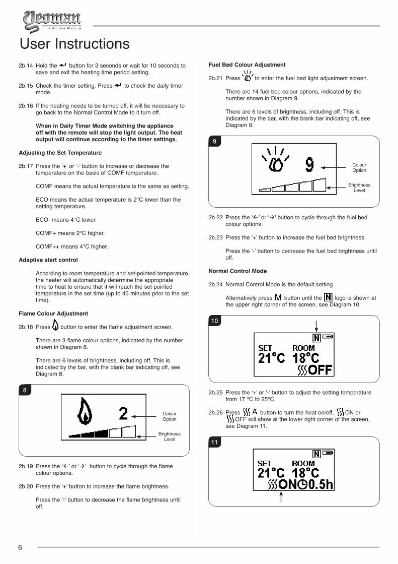
Flame Colour Adjustment
2b.18 Press button to enter the flame adjustment screen.
There are 3 flame colour options, indicated by the number shown in Diagram 8.
There are 6 levels of brightness, including off. This is indicated by the bar, with the blank bar indicating off, see Diagram 8.
Brightness Level
Colour Option
8
2b.19 Press the ‘’ or ‘’ button to cycle through the flame colour options.
2b.20 Press the ‘+’ button to increase the flame brightness.
Press the ‘-’ button to decrease the flame brightness until off.
Fuel Bed Colour Adjustment
2b.21 Press to enter the fuel bed light adjustment screen.
There are 14 fuel bed colour options, indicated by the number shown in Diagram 9.
There are 6 levels of brightness, including off. This is indicated by the bar, with the blank bar indicating off, see Diagram 9.
Brightness Level
Colour Option
9
2b.22 Press the ‘’ or ‘’ button to cycle through the fuel bed colour options.
2b.23 Press the ‘+’ button to increase the fuel bed brightness.
Press the ‘-’ button to decrease the fuel bed brightness until off.
Normal Control Mode
2b.24 Normal Control Mode is the default setting.
Alternatively press button until the logo is shown at the upper right corner of the screen, see Diagram 10.
10
2b.25 Press the ‘+’ or ‘-’ button to adjust the setting temperature from 17 ℃ to 25℃.
2b.26 Press button to turn the heat on/off, ON or OFF will show at the lower right corner of the screen,
see Diagram 11.
11
User Instructions
7
Note: It is normal for the fan heater to stop running for periods of time. This happens if the room temperature is higher than the temperature set on the control.
The heater indicator will be turned off after 10s if the flame is switched ON. The heater indicator will stay ON if only the heating function is used.
When in Normal Control Mode switching the appliance off with the remote will stop both the light and heat output.
Count Down Timer
This setting is only in normal heating control mode. It allows the appliance to be returned to Standby after a set period of time. The heater must be switched on to use this function.
2b.27 Press to cycle through the setting from Off and 0.5 hours to 9 hours. Timer logo and remaining time will show on the screen.
The heater of appliance can be automatically run by using daily timer and weekly timer on the remote.
Battery
The battery power level is indicated at the top right of the remote control screen, see Diagram 3.
Battery Full No action required Battery Half Power Ensure new batteries are available. Battery Empty Replace batteries immediately
Battery replacement is recommended after 1 year. The Remote requires two 1.5V alkaline AAA batteries.
Changing the batteries will not affect the Timer Mode settings, however, the clock may need adjusting.
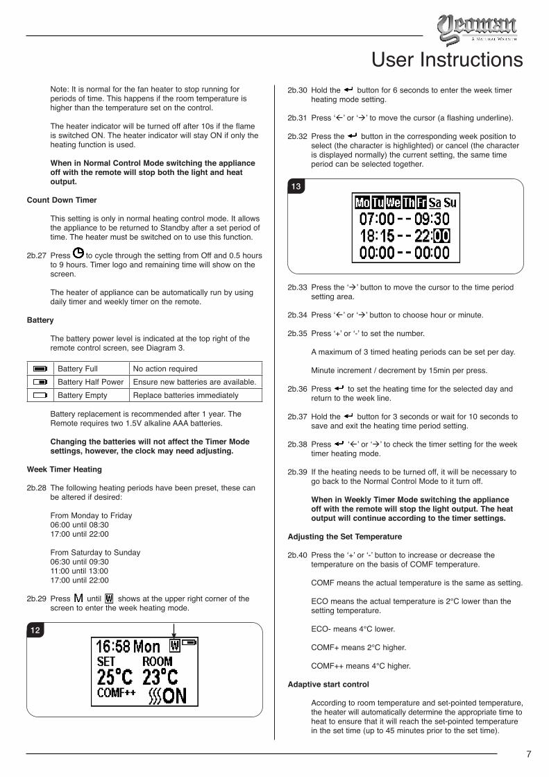
Week Timer Heating
2b.28 The following heating periods have been preset, these can be altered if desired:
From Monday to Friday 06:00 until 08:30 17:00 until 22:00
From Saturday to Sunday 06:30 until 09:30 11:00 until 13:00 17:00 until 22:00
2b.29 Press until shows at the upper right corner of the screen to enter the week heating mode.
12
2b.30 Hold the button for 6 seconds to enter the week timer heating mode setting.
2b.31 Press ‘’ or ‘’ to move the cursor (a flashing underline).
2b.32 Press the button in the corresponding week position to select (the character is highlighted) or cancel (the character is displayed normally) the current setting, the same time period can be selected together.
13
2b.33 Press the ‘’ button to move the cursor to the time period setting area.
2b.34 Press ‘’ or ‘’ button to choose hour or minute.
2b.35 Press ‘+’ or ‘-’ to set the number.
A maximum of 3 timed heating periods can be set per day.
Minute increment / decrement by 15min per press.
2b.36 Press to set the heating time for the selected day and return to the week line.
2b.37 Hold the button for 3 seconds or wait for 10 seconds to save and exit the heating time period setting.
2b.38 Press ‘’ or ‘’ to check the timer setting for the week timer heating mode.
2b.39 If the heating needs to be turned off, it will be necessary to go back to the Normal Control Mode to it turn off.
When in Weekly Timer Mode switching the appliance off with the remote will stop the light output. The heat output will continue according to the timer settings.
Adjusting the Set Temperature
2b.40 Press the ‘+’ or ‘-’ button to increase or decrease the temperature on the basis of COMF temperature.
COMF means the actual temperature is the same as setting.
ECO means the actual temperature is 2℃ lower than the setting temperature.
ECO- means 4℃ lower.
COMF+ means 2℃ higher.
COMF++ means 4℃ higher.
Adaptive start control
According to room temperature and set-pointed temperature, the heater will automatically determine the appropriate time to heat to ensure that it will reach the set-pointed temperature in the set time (up to 45 minutes prior to the set time).
User Instructions
8
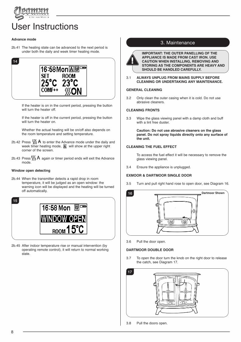
Advance mode
2b.41 The heating state can be advanced to the next period is under both the daily and week timer heating mode.
14
If the heater is on in the current period, pressing the button will turn the heater off.
If the heater is off in the current period, pressing the button will turn the heater on.
Whether the actual heating will be on/off also depends on the room temperature and setting temperature.
2b.42 Press to enter the Advance mode under the daily and week timer heating mode, will show at the upper right corner of the screen.
2b.43 Press again or timer period ends will exit the Advance mode.
Window open detecting
2b.44 When the transmitter detects a rapid drop in room temperature, it will be judged as an open window: the warning icon will be displayed and the heating will be turned off automatically.
15
2b.45 After indoor temperature rise or manual intervention (by operating remote control), it will return to normal working state.
3. Maintenance
IMPORTANT: THE OUTER PANELLING OF THE APPLIANCE IS MADE FROM CAST IRON. USE CAUTION WHEN INSTALLING, REMOVING AND STORING AS THE COMPONENTS ARE HEAVY AND SHOULD BE HANDLED CAREFULLY.
3.1 ALWAYS UNPLUG FROM MAINS SUPPLY BEFORE CLEANING OR UNDERTAKING ANY MAINTENANCE.
GENERAL CLEANING
3.2 Only clean the outer casing when it is cold. Do not use abrasive cleaners.
CLEANING FRONTS
3.3 Wipe the glass viewing panel with a damp cloth and buff with a lint free duster.
Caution: Do not use abrasive cleaners on the glass panel. Do not spray liquids directly onto any surface of the unit.
CLEANING THE FUEL EFFECT
To access the fuel effect it will be necessary to remove the glass viewing panel.
3.4 Ensure the appliance is unplugged.
EXMOOR & DARTMOOR SINGLE DOOR
3.5 Turn and pull right hand rose to open door, see Diagram 16.
16 Dartmoor Shown
3.6 Pull the door open.
DARTMOOR DOUBLE DOOR
3.7 To open the door turn the knob on the right door to release the catch, see Diagram 17.
17
3.8 Pull the doors open.
User Instructions
9
User InstructionsALL MODELS
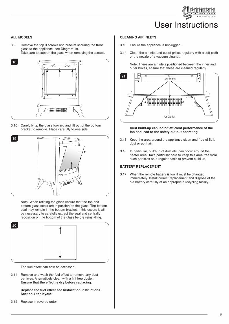
3.9 Remove the top 3 screws and bracket securing the front glass to the appliance, see Diagram 18.
Take care to support the glass when removing the screws.
18
3.10 Carefully tip the glass forward and lift out of the bottom bracket to remove. Place carefully to one side.
19
Note: When refitting the glass ensure that the top and bottom glass seals are in position on the glass. The bottom seal may remain in the bottom bracket, if this occurs it will be necessary to carefully extract the seal and centrally reposition on the bottom of the glass before reinstalling.
20
The fuel effect can now be accessed.
3.11 Remove and wash the fuel effect to remove any dust particles. Alternatively clean with a lint free duster.
Ensure that the effect is dry before replacing.
Replace the fuel effect see Installation Instructions Section 4 for layout.
3.12 Replace in reverse order.
CLEANING AIR INLETS
3.13 Ensure the appliance is unplugged.
3.14 Clean the air inlet and outlet grilles regularly with a soft cloth or the nozzle of a vacuum cleaner.
Note: There are air inlets positioned between the inner and outer boxes, ensure that these are cleaned regularly.
21
Air Outlet
Air Inlets
Dust build-up can inhibit efficient performance of the fan and lead to the safety cut-out operating.
3.15 Keep the area around the appliance clean and free of fluff, dust or pet hair.
3.16 In particular, build-up of dust etc. can occur around the heater area. Take particular care to keep this area free from such particles on a regular basis to prevent build-up.
BATTERY REPLACEMENT
3.17 When the remote battery is low it must be changed immediately. Install correct replacement and dispose of the old battery carefully at an appropriate recycling facility.
10
Installation Instructions
A 230V 13A 50Hz supply is required Maximum power consumption: Yeoman Exmoor: 1500 Watts Yeoman Dartmoor: 1500 Watts
THIS APPLIANCE MUST BE EARTHED
A 1.8 metre lead with a BS1363 plug containing a BS1362 13A fuse is supplied. Only use a BS1362 13A fuse with this appliance.
2 x Remote control handset battery (AAA)
These instructions cover the following models:
PACKING CHECKLIST
Appliance Description Fixing Kit containing:
Yeoman ExmoorYeoman Dartmoor
1 x Instruction Manual1 x Handset2 x AAA Batteries1 x Power CableGrey Pebble EffectClear Pebble EffectSmall Glass-Effect CrystalsLarge Glass-Effect CrystalsLog Set
Technical Specification
Control System Technical Data
Main Control Board Remote Receiver Board Remote Control
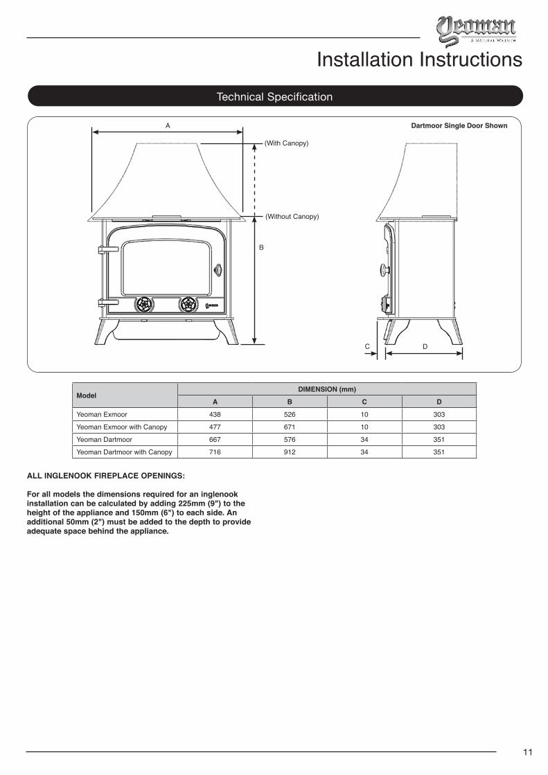
For all models the dimensions required for an inglenook installation can be calculated by adding 225mm (9") to the height of the appliance and 150mm (6") to each side. An additional 50mm (2") must be added to the depth to provide adequate space behind the appliance.
Technical Specification
ModelDIMENSION (mm)
A B C D
Yeoman Exmoor 438 526 10 303
Yeoman Exmoor with Canopy 477 671 10 303
Yeoman Dartmoor 667 576 34 351
Yeoman Dartmoor with Canopy 716 912 34 351
A
B
C D
(With Canopy)
(Without Canopy)
Dartmoor Single Door Shown
12
Installation Instructions1. General
1.1 TOOLS REQUIRED
No tools are required to install this appliance.
1.2 UNPACKING THE FIREPLACE
WARNING! DO NOT use this appliance if any part has been exposed to water.
Immediately call a qualified service technician to inspect and to replace any part of the electrical system if necessary.
1.3 Open the packaging carefully and remove the polystyrene. Remove and discard the plastic bag. Keep plastic wrapping away from children. Be responsible when handling the packing materials.
1.4 Check all parts and accessories are removed before disposing of any packaging.
If necessary keep the original packaging for future transport and/or storage.
This appliance is heavy and does not require anchoring to the hearth or floor, but in certain circumstances the appliance can become unstable e.g. when leaning on the appliance. If this is likely, secure the appliance to the hearth or floor with suitably strong fixings.
2. Locating the Appliance
The appliance may be installed virtually anywhere in your home. However, when choosing a location ensure that the general instructions are followed.
2.1 For best results, install out of direct sunlight.
2.2 If the power cord is damaged contact your Yeoman retailer for a replacement. Only use genuine Yeoman parts on this appliance.
2.3 The appliance should be located close to a suitable mains
socket to enable connection. The electrical socket must be easily accessible to allow
disconnection when the appliance is fitted.
2.4 This appliance must stand on a clean, level, firm surface. Do not stand the appliance on a carpet. Ensure that furniture, curtains etc. are positioned no closer than 1m and the appliance stands on a surface that can withstand temperatures of 90°C for prolonged periods. Do not allow rugs to be placed within 500mm of the front of the appliance.
2.5 Ensure that curtains and furniture are not positioned close to the chosen position, as this would create a potential fire hazard or block the heater outlet ducts.
WARNING! KEEP ANY COMBUSTIBLE MATERIALS AT LEAST 1M FROM THE FRONT AND SIDES OF THE APPLIANCE.
ALL INGLENOOK FIREPLACE OPENINGS:
For all models the dimensions required for an inglenook installation can be calculated by adding 225mm (9") to the height of the appliance and 150mm (6") to each side. An additional 50mm (2") must be added to the depth to provide adequate space behind the appliance.
3. Fitting the Appliance
IMPORTANT: THE OUTER PANELLING IS MADE FROM CAST IRON. USE CAUTION WHEN INSTALLING, REMOVING AND STORING AS THE COMPONENTS ARE HEAVY AND SHOULD BE HANDLED CAREFULLY.
3.1 Position the stove ensuring all appropriate clearances are observed.
EXMOOR & DARTMOOR SINGLE DOOR
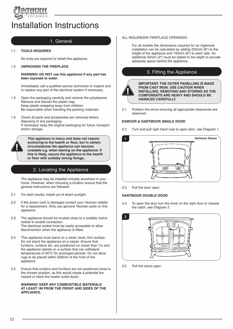
3.2 Turn and pull right hand rose to open door, see Diagram 1.
1 Dartmoor Shown
3.3 Pull the door open.
DARTMOOR DOUBLE DOOR
3.4 To open the door turn the knob on the right door to release the catch, see Diagram 2.
2
3.5 Pull the doors open.
13
ALL MODELS
3.6 Remove the top 3 screws and bracket securing the front glass to the appliance, see Diagram 3.
Take care to support the glass when removing the screws.
3
3.7 Carefully tip the glass forward and lift out of the bottom bracket to remove. Place carefully to one side.
4
4. Fuel Effect
4.1 The appliance is supplied with 2 fuel effect options:
4a. Log Effect. 4b. Crystal Ice Glass Effect.
4a. Log Effect
LOGS MUST BE POSITIONED ACCORDING TO THE FOLLOWING INSTRUCTIONS TO GIVE THE CORRECT FLAME EFFECT.
The logs for the fuel bed are NOT individually labelled, the numbers are for reference information only.
4a.1 Evenly spread the clear pebble effect across the fuel bed.
4a.2 Randomly space the grey pebble effect throughout the fuel bed, partially covering the clear pebbles.
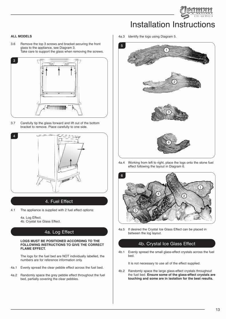
Installation Instructions4a.3 Identify the logs using Diagram 5.
51
2
3
4
4a.4 Working from left to right, place the logs onto the stone fuel effect following the layout in Diagram 6.
1
2
3
4
6
4a.5 If desired the Crystal Ice Glass Effect can be placed in between the log layout.
4b. Crystal Ice Glass Effect4b.1 Evenly spread the small glass-effect crystals across the fuel
bed.
It is not necessary to use all of the effect supplied.
4b.2 Randomly space the large glass-effect crystals throughout the fuel bed. Ensure some of the glass-effect crystals are touching and some are in isolation for the best results.
14
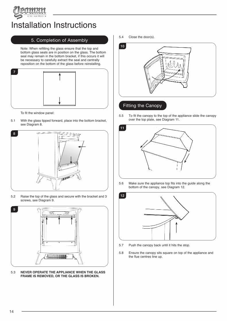
5. Completion of Assembly Note: When refitting the glass ensure that the top and
bottom glass seals are in position on the glass. The bottom seal may remain in the bottom bracket, if this occurs it will be necessary to carefully extract the seal and centrally reposition on the bottom of the glass before reinstalling.
7
To fit the window panel:
5.1 With the glass tipped forward, place into the bottom bracket, see Diagram 8.
8
5.2 Raise the top of the glass and secure with the bracket and 3 screws, see Diagram 9.
9
5.3 NEVER OPERATE THE APPLIANCE WHEN THE GLASS FRAME IS REMOVED, OR THE GLASS IS BROKEN.
Installation Instructions5.4 Close the door(s).
10
Fitting the Canopy
5.5 To fit the canopy to the top of the appliance slide the canopy over the top plate, see Diagram 11.
11
5.6 Make sure the appliance top fits into the guide along the bottom of the canopy, see Diagram 12.
12
5.7 Push the canopy back until it hits the stop.
5.8 Ensure the canopy sits square on top of the appliance and the flue centres line up.
15
Servicing Instructions1. Fault Finding
No illumination or uneven lighting:
1.1 First change the BS1362 13A fuse for one known to work. If the appliance still does not work, check the socket by plugging in a working appliance. If this too fails to operate, call in a competent electrician to check the socket.
1.2 One or more of the LED boards may need replacing. This must be undertaken by a suitably qualified person (see Servicing Requirements).
Illumination but no heat:
1.3 The safety cut-out may have operated to protect against overheating (see User Instructions, Section 2). Ensure the air inlet and outlet grilles are free of dust or any other obstruction.
1.4 The thermostat control may be set too low. Increase the
setting by pressing the thermostat button on the remote control until the heater turns on.
Remote control fails to work:
1.5 Check that the batteries are new and correctly fitted. Replace if necessary.
2. How to wire a plug To change the plug supplied with this appliance, follow the
instructions below. The instructions assume that the wire has been cut.
WARNING – FAILURE TO CONNECT THE WIRES CORRECTLY COULD PUT PEOPLE AT RISK FROM ELECTRIC SHOCK OR FIRE. IF IN DOUBT CONSULT A QUALIFIED ELECTRICIAN.
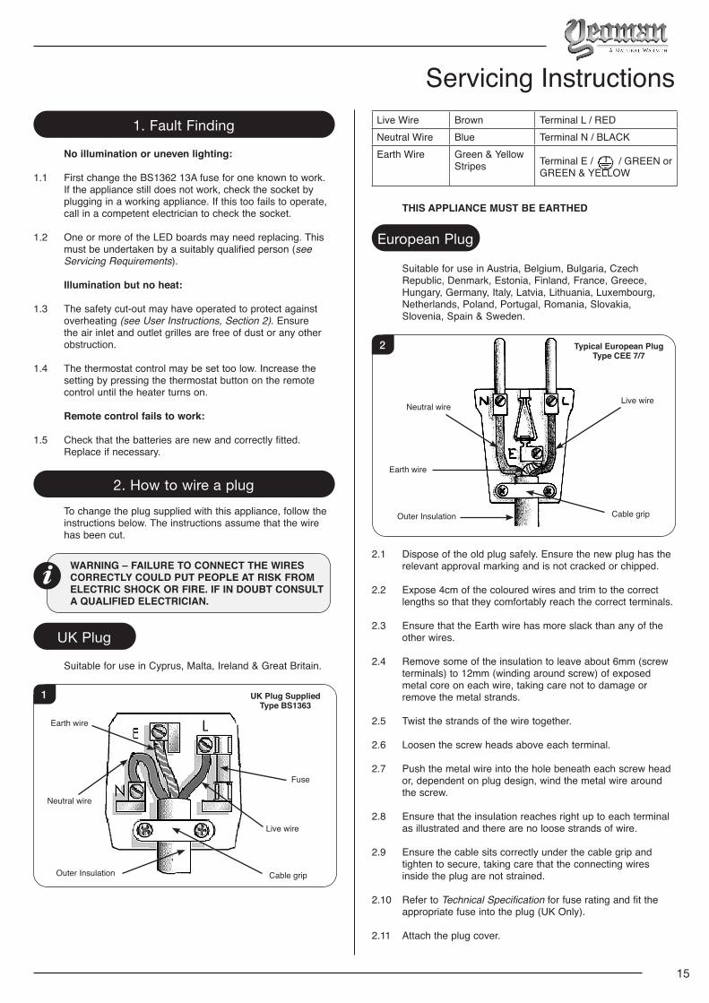
UK Plug
Suitable for use in Cyprus, Malta, Ireland & Great Britain.
1
Earth wire
Neutral wire
Outer Insulation
Fuse
Cable grip
UK Plug SuppliedType BS1363
Live wire
Live Wire Brown Terminal L / REDNeutral Wire Blue Terminal N / BLACKEarth Wire Green & Yellow
Stripes Terminal E / / GREEN or GREEN & YELLOW
THIS APPLIANCE MUST BE EARTHED
European Plug
Suitable for use in Austria, Belgium, Bulgaria, Czech Republic, Denmark, Estonia, Finland, France, Greece, Hungary, Germany, Italy, Latvia, Lithuania, Luxembourg, Netherlands, Poland, Portugal, Romania, Slovakia, Slovenia, Spain & Sweden.
Cable gripOuter Insulation
Neutral wire
Earth wire
Live wire
Typical European PlugType CEE 7/7
2
2.1 Dispose of the old plug safely. Ensure the new plug has the relevant approval marking and is not cracked or chipped.
2.2 Expose 4cm of the coloured wires and trim to the correct lengths so that they comfortably reach the correct terminals.
2.3 Ensure that the Earth wire has more slack than any of the other wires.
2.4 Remove some of the insulation to leave about 6mm (screw terminals) to 12mm (winding around screw) of exposed metal core on each wire, taking care not to damage or remove the metal strands.
2.5 Twist the strands of the wire together.
2.6 Loosen the screw heads above each terminal.
2.7 Push the metal wire into the hole beneath each screw head or, dependent on plug design, wind the metal wire around the screw.
2.8 Ensure that the insulation reaches right up to each terminal as illustrated and there are no loose strands of wire.
2.9 Ensure the cable sits correctly under the cable grip and tighten to secure, taking care that the connecting wires inside the plug are not strained.
2.10 Refer to Technical Specification for fuse rating and fit the appropriate fuse into the plug (UK Only).
2.11 Attach the plug cover.
16
Servicing Instructions3. Servicing Requirements
DURING SERVICING OF THIS APPLIANCE IT MAY BE NECESSARY TO CUT CABLE TIES IN ORDER TO ACCESS AND REMOVE SOME OF THE PARTS.THESE MUST BE REPLACED WHEN REASSEMBLING THE APPLIANCE.
WARNING: The Effect Spindles are sharp, please use caution when servicing this appliance.
THIS APPLIANCE MUST ONLY BE SERVICED BY A SUITABLY QUALIFIED PERSON.
BEFORE UNDERTAKING ANY WORK ON THE APPLIANCE: SWITCH OFF THE APPLIANCE AND ISOLATE THE POWER SUPPLY ENSURING THERE IS NO POWER TO THE APPLIANCE.
3.1 Wait for at least 10 minutes until the appliance has cooled down.
3.2 Remote Handset Battery Replacement
Replace with 2 AAA batteries. Make sure the batteries are installed correctly in the remote control.
3.3 Maintenance of Motors
The motor used on the flame effect is pre-lubricated for extended bearing life and requires no further lubrication. However, periodic cleaning/vacuuming of the heater unit is recommended.
3.4 Resetting the Thermal Cutout Switch
The appliance is fitted with an Electronic Safety Control (E.S.). This is a safety device which switches off the fire if, the appliance overheats for any reason e.g. when covered.
If the heater stops operating whilst the flame effect
continues normally, this indicates that the E.S. Control is in operation.
The E.S. Control can only be re-set after the appliance has cooled down.
To re-set the E.S: Switch off the appliance (Manual On/Off switch) and leave
for approximately 2 hours. Remove any obstruction to the fan heater outlet or other
internal parts. Switch on appliance and the E.S. Control will re-set. Ensure
that the appliance is functioning correctly. If the E.S. Control operates again, the appliance should be checked by a competent Electrician.
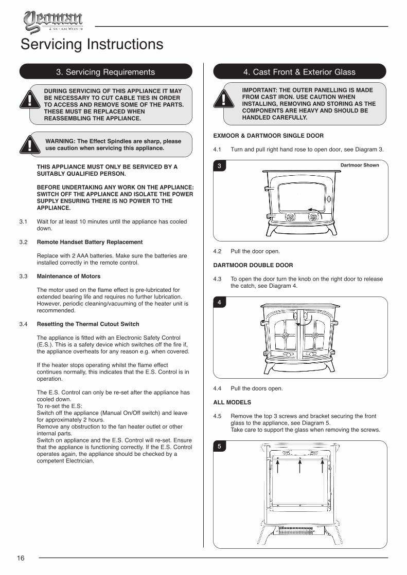
4. Cast Front & Exterior Glass
IMPORTANT: THE OUTER PANELLING IS MADE FROM CAST IRON. USE CAUTION WHEN INSTALLING, REMOVING AND STORING AS THE COMPONENTS ARE HEAVY AND SHOULD BE HANDLED CAREFULLY.
EXMOOR & DARTMOOR SINGLE DOOR
4.1 Turn and pull right hand rose to open door, see Diagram 3.
3 Dartmoor Shown
4.2 Pull the door open.
DARTMOOR DOUBLE DOOR
4.3 To open the door turn the knob on the right door to release the catch, see Diagram 4.
4
4.4 Pull the doors open.
ALL MODELS
4.5 Remove the top 3 screws and bracket securing the front glass to the appliance, see Diagram 5.
Take care to support the glass when removing the screws.
5
17
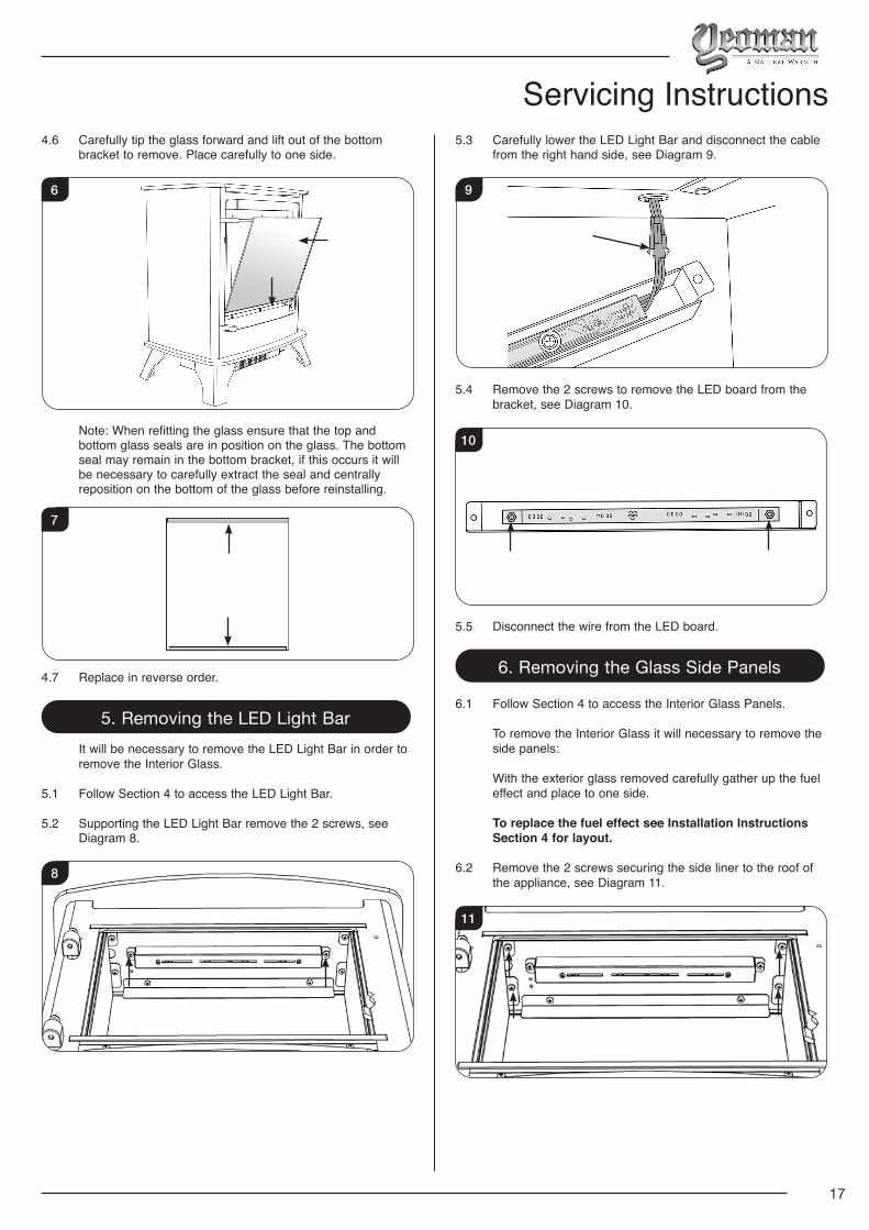
Servicing Instructions4.6 Carefully tip the glass forward and lift out of the bottom
bracket to remove. Place carefully to one side.
6
Note: When refitting the glass ensure that the top and bottom glass seals are in position on the glass. The bottom seal may remain in the bottom bracket, if this occurs it will be necessary to carefully extract the seal and centrally reposition on the bottom of the glass before reinstalling.
7
4.7 Replace in reverse order.
5. Removing the LED Light Bar It will be necessary to remove the LED Light Bar in order to
remove the Interior Glass.
5.1 Follow Section 4 to access the LED Light Bar.
5.2 Supporting the LED Light Bar remove the 2 screws, see Diagram 8.
8
5.3 Carefully lower the LED Light Bar and disconnect the cable from the right hand side, see Diagram 9.
9
5.4 Remove the 2 screws to remove the LED board from the bracket, see Diagram 10.
10
5.5 Disconnect the wire from the LED board.
6. Removing the Glass Side Panels
6.1 Follow Section 4 to access the Interior Glass Panels.
To remove the Interior Glass it will necessary to remove the side panels:
With the exterior glass removed carefully gather up the fuel effect and place to one side.
To replace the fuel effect see Installation Instructions Section 4 for layout.
6.2 Remove the 2 screws securing the side liner to the roof of the appliance, see Diagram 11.
11
18
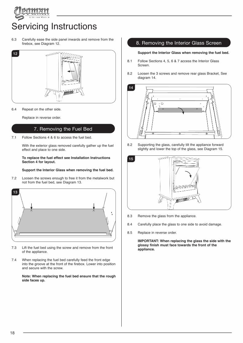
6.3 Carefully ease the side panel inwards and remove from the firebox, see Diagram 12.
12
6.4 Repeat on the other side.
Replace in reverse order.
7. Removing the Fuel Bed7.1 Follow Sections 4 & 6 to access the fuel bed.
With the exterior glass removed carefully gather up the fuel effect and place to one side.
To replace the fuel effect see Installation Instructions Section 4 for layout.
Support the Interior Glass when removing the fuel bed.
7.2 Loosen the screws enough to free it from the metalwork but not from the fuel bed, see Diagram 13.
13
7.3 Lift the fuel bed using the screw and remove from the front of the appliance.
7.4 When replacing the fuel bed carefully feed the front edge into the groove at the front of the firebox. Lower into position and secure with the screw.
Note: When replacing the fuel bed ensure that the rough side faces up.
Servicing Instructions8. Removing the Interior Glass Screen
Support the Interior Glass when removing the fuel bed.
8.2 Loosen the 3 screws and remove rear glass Bracket, See diagram 14.
14
8.2 Supporting the glass, carefully tilt the appliance forward slightly and lower the top of the glass, see Diagram 15.
15
8.3 Remove the glass from the appliance.
8.4 Carefully place the glass to one side to avoid damage.
8.5 Replace in reverse order.
IMPORTANT: When replacing the glass the side with the glossy finish must face towards the front of the appliance.
19
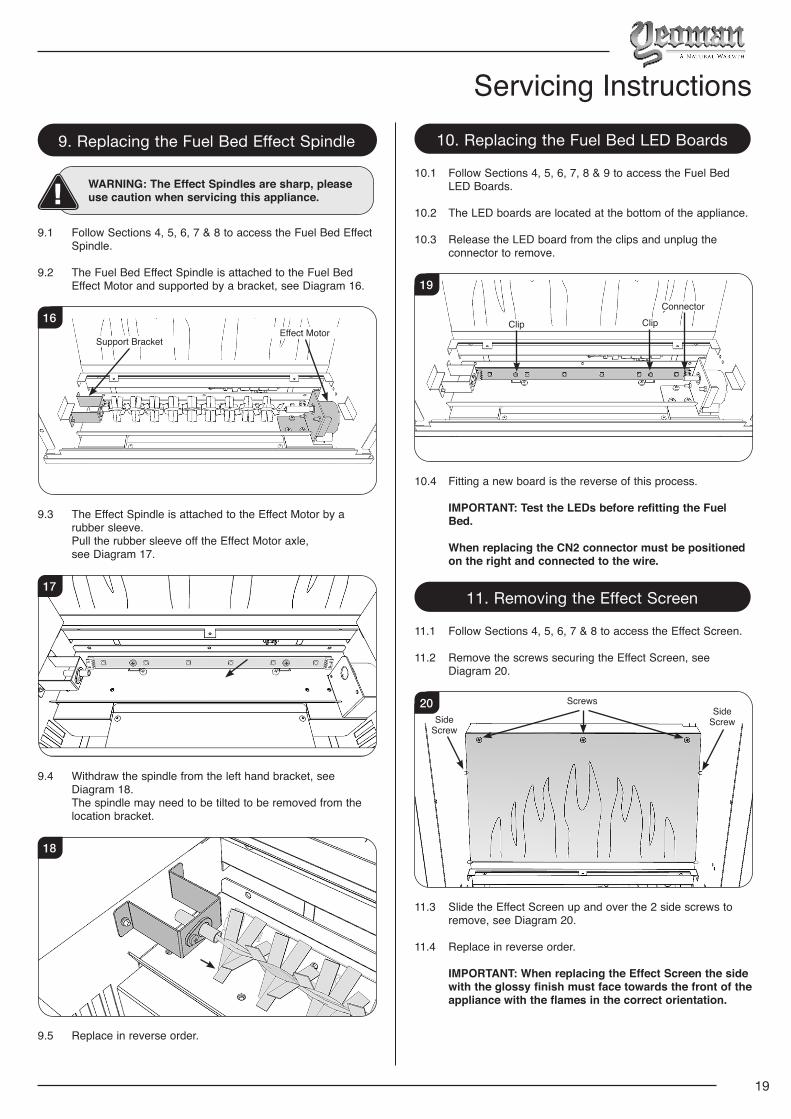
Servicing Instructions9. Replacing the Fuel Bed Effect Spindle
WARNING: The Effect Spindles are sharp, please use caution when servicing this appliance.
9.1 Follow Sections 4, 5, 6, 7 & 8 to access the Fuel Bed Effect
Spindle.
9.2 The Fuel Bed Effect Spindle is attached to the Fuel Bed Effect Motor and supported by a bracket, see Diagram 16.
Effect MotorSupport Bracket
16
9.3 The Effect Spindle is attached to the Effect Motor by a rubber sleeve.
Pull the rubber sleeve off the Effect Motor axle, see Diagram 17.
17
9.4 Withdraw the spindle from the left hand bracket, see Diagram 18.
The spindle may need to be tilted to be removed from the location bracket.
18
9.5 Replace in reverse order.
10. Replacing the Fuel Bed LED Boards
10.1 Follow Sections 4, 5, 6, 7, 8 & 9 to access the Fuel Bed LED Boards.
10.2 The LED boards are located at the bottom of the appliance.
10.3 Release the LED board from the clips and unplug the connector to remove.
19
Clip ClipConnector
10.4 Fitting a new board is the reverse of this process.
IMPORTANT: Test the LEDs before refitting the Fuel Bed.
When replacing the CN2 connector must be positioned on the right and connected to the wire.
11. Removing the Effect Screen
11.1 Follow Sections 4, 5, 6, 7 & 8 to access the Effect Screen.
11.2 Remove the screws securing the Effect Screen, see Diagram 20.
20Side
Screw
Side Screw
Screws
11.3 Slide the Effect Screen up and over the 2 side screws to remove, see Diagram 20.
11.4 Replace in reverse order.
IMPORTANT: When replacing the Effect Screen the side with the glossy finish must face towards the front of the appliance with the flames in the correct orientation.
20
12. Replacing the Flame Effect Spindle
WARNING: The Effect Spindles are sharp, please use caution when servicing this appliance.
12.1 Follow Sections 4, 5, 6, 7, 8 & 11 to access the Flame Effect
Spindle.
12.2 The Flame Effect Spindle is attached to the Flame Effect Motor and supported by a bracket, see Diagram 21.
21Effect MotorSupport Bracket
12.3 The Effect Spindle is attached to the Effect Motor by a rubber sleeve.
Pull the rubber sleeve off the Effect Motor axle, see Diagram 22.
22
12.4 Withdraw the spindle from the left hand bracket, see Diagram 23.
The spindle may need to be tilted to be removed from the location bracket.
23
12.5 Replace in reverse order. Take care not to damage the spindle blades when replacing.
13. Replacing the Flame Effect LED Board
WARNING: The Effect Spindles are sharp, please use caution when servicing this appliance.
13.1 Follow Sections 4, 5, 6, 7, 8, 11 & 12 to access the Flame
Effect LED Board.
The Flame Effect LED Board is held in place by clips.
13.2 Reach over the Light Shield and locate the left hand clip, see Diagrams 24 & 25.
Light Shield
24
Light Shield removed for clarity
Clamp ClampLED Board
25
13.3 Push the rear clamp towards the rear of the firebox to release the board, see Diagram 26.
26
13.4 Repeat for the other side.
13.5 Gently withdraw the LED Board.
Servicing Instructions
21
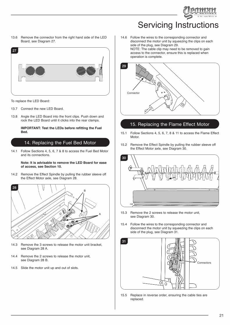
13.6 Remove the connector from the right hand side of the LED Board, see Diagram 27.
27
To replace the LED Board:
13.7 Connect the new LED Board.
13.8 Angle the LED Board into the front clips. Push down and rock the LED Board until it clicks into the rear clamps.
IMPORTANT: Test the LEDs before refitting the Fuel Bed.
14. Replacing the Fuel Bed Motor14.1 Follow Sections 4, 5, 6, 7 & 8 to access the Fuel Bed Motor
and its connections.
Note: It is advisable to remove the LED Board for ease of access, see Section 10.
14.2 Remove the Effect Spindle by pulling the rubber sleeve off the Effect Motor axle, see Diagram 28.
28B
A
14.3 Remove the 3 screws to release the motor unit bracket, see Diagram 28 A.
14.4 Remove the 2 screws to release the motor unit, see Diagram 28 B.
14.5 Slide the motor unit up and out of slots.
14.6 Follow the wires to the corresponding connector and disconnect the motor unit by squeezing the clips on each side of the plug, see Diagram 29.
NOTE: The cable clip may need to be removed to gain access to the connector, ensure this is replaced when operation is complete.
29
Connector
15. Replacing the Flame Effect Motor
15.1 Follow Sections 4, 5, 6, 7, 8 & 11 to access the Flame Effect Motor.
15.2 Remove the Effect Spindle by pulling the rubber sleeve off the Effect Motor axle, see Diagram 30.
30
15.3 Remove the 2 screws to release the motor unit, see Diagram 30.
15.4 Follow the wires to the corresponding connector and disconnect the motor unit by squeezing the clips on each side of the plug, see Diagram 31.
31
Connectors
15.5 Replace in reverse order, ensuring the cable ties are replaced.
Servicing Instructions
22
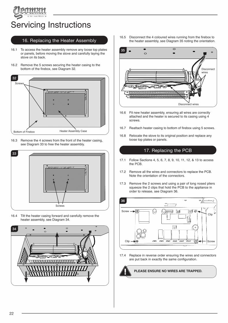
16. Replacing the Heater Assembly
16.1 To access the heater assembly remove any loose top plates or panels, before moving the stove and carefully laying the stove on its back.
16.2 Remove the 5 screws securing the heater casing to the bottom of the firebox, see Diagram 32.
Screws
Heater Assembly CaseBottom of Firebox
32
16.3 Remove the 4 screws from the front of the heater casing, see Diagram 33 to free the heater assembly.
Screws
33
16.4 Tilt the heater casing forward and carefully remove the heater assembly, see Diagram 34.
34
16.5 Disconnect the 4 coloured wires running from the firebox to the heater assembly, see Diagram 35 noting the orientation.
Disconnect wires
Disconnect wires
35
16.6 Fit new heater assembly, ensuring all wires are correctly attached and the heater is secured to its casing using 4 screws.
16.7 Reattach heater casing to bottom of firebox using 5 screws.
16.8 Relocate the stove to its original position and replace any loose top plates or panels.
17. Replacing the PCB
17.1 Follow Sections 4, 5, 6, 7, 8, 9, 10, 11, 12, & 13 to access the PCB.
17.2 Remove all the wires and connectors to replace the PCB. Note the orientation of the connectors.
17.3 Remove the 2 screws and using a pair of long nosed pliers squeeze the 2 clips that hold the PCB to the appliance in order to release, see Diagram 36.
Screw
ScrewClip
Clip
36
17.4 Replace in reverse order ensuring the wires and connectors are put back in exactly the same configuration.
PLEASE ENSURE NO WIRES ARE TRAPPED.
Servicing Instructions
23
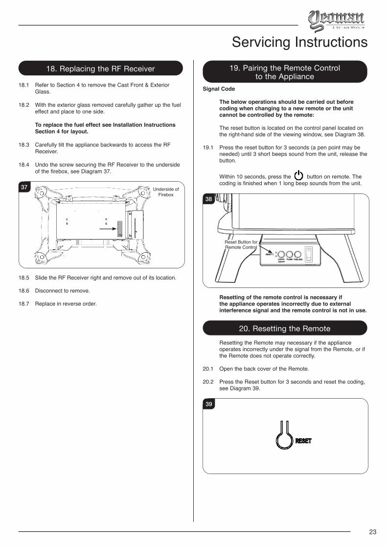
18. Replacing the RF Receiver
18.1 Refer to Section 4 to remove the Cast Front & Exterior Glass.
18.2 With the exterior glass removed carefully gather up the fuel effect and place to one side.
To replace the fuel effect see Installation Instructions Section 4 for layout.
18.3 Carefully tilt the appliance backwards to access the RF Receiver.
18.4 Undo the screw securing the RF Receiver to the underside of the firebox, see Diagram 37.
Underside of Firebox
37
18.5 Slide the RF Receiver right and remove out of its location.
18.6 Disconnect to remove.
18.7 Replace in reverse order.
19. Pairing the Remote Control to the Appliance
Signal Code
The below operations should be carried out before coding when changing to a new remote or the unit cannot be controlled by the remote:
The reset button is located on the control panel located on the right-hand side of the viewing window, see Diagram 38.
19.1 Press the reset button for 3 seconds (a pen point may be needed) until 3 short beeps sound from the unit, release the button.
Within 10 seconds, press the button on remote. The coding is finished when 1 long beep sounds from the unit.
Reset Button for Remote Control
38
Resetting of the remote control is necessary if the appliance operates incorrectly due to external interference signal and the remote control is not in use.
20. Resetting the Remote Resetting the Remote may necessary if the appliance
operates incorrectly under the signal from the Remote, or if the Remote does not operate correctly.
20.1 Open the back cover of the Remote.
20.2 Press the Reset button for 3 seconds and reset the coding, see Diagram 39.
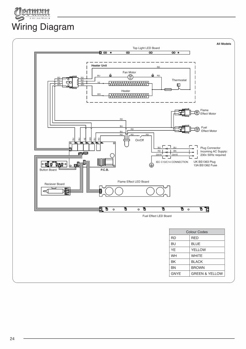
IEC C13/C14 CONNECTION UK BS1363 Plug13A BS1362 Fuse
Fuel Effect LED Board
Flame Effect LED BoardReciever Board
Button Board P.C.B.
Heater Unit
Top Light LED Board
Fan Motor
Heater
Thermostat
FlameEffect Motor
FuelEffect Motor
Plug Connector Incoming AC Supply:230v 50Hz required
On/Off
All Models
25
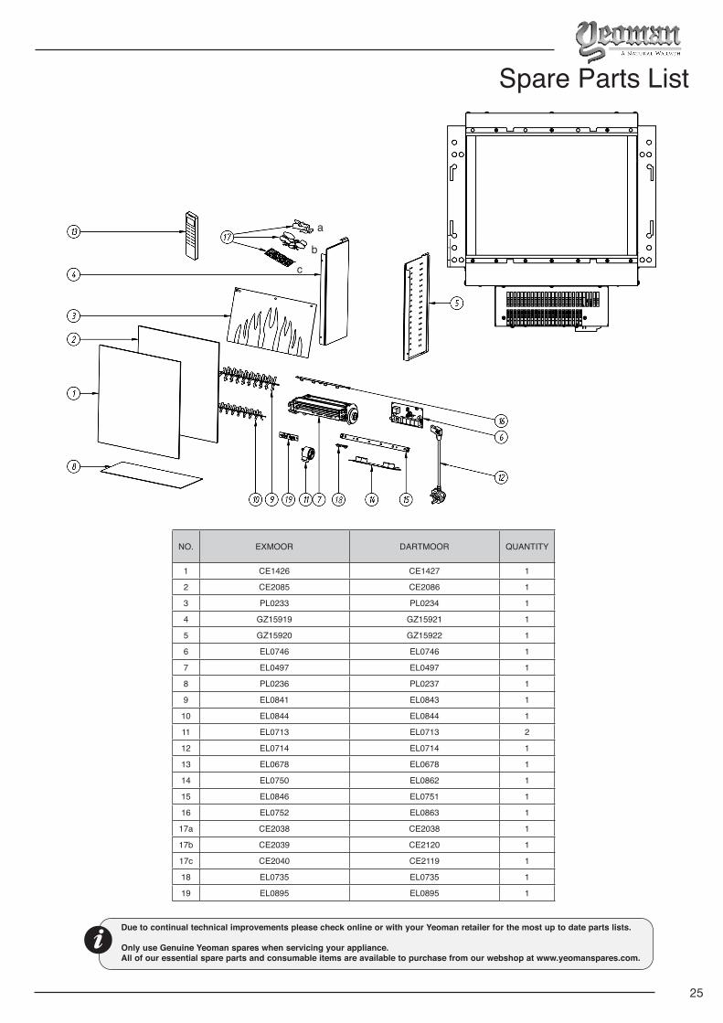
Spare Parts List
Due to continual technical improvements please check online or with your Yeoman retailer for the most up to date parts lists.
Only use Genuine Yeoman spares when servicing your appliance. All of our essential spare parts and consumable items are available to purchase from our webshop at www.yeomanspares.com.
a
b
c
NO. EXMOOR DARTMOOR QUANTITY
1 CE1426 CE1427 1
2 CE2085 CE2086 1
3 PL0233 PL0234 1
4 GZ15919 GZ15921 1
5 GZ15920 GZ15922 1
6 EL0746 EL0746 1
7 EL0497 EL0497 1
8 PL0236 PL0237 1
9 EL0841 EL0843 1
10 EL0844 EL0844 1
11 EL0713 EL0713 2
12 EL0714 EL0714 1
13 EL0678 EL0678 1
14 EL0750 EL0862 1
15 EL0846 EL0751 1
16 EL0752 EL0863 1
17a CE2038 CE2038 1
17b CE2039 CE2120 1
17c CE2040 CE2119 1
18 EL0735 EL0735 1
19 EL0895 EL0895 1
26
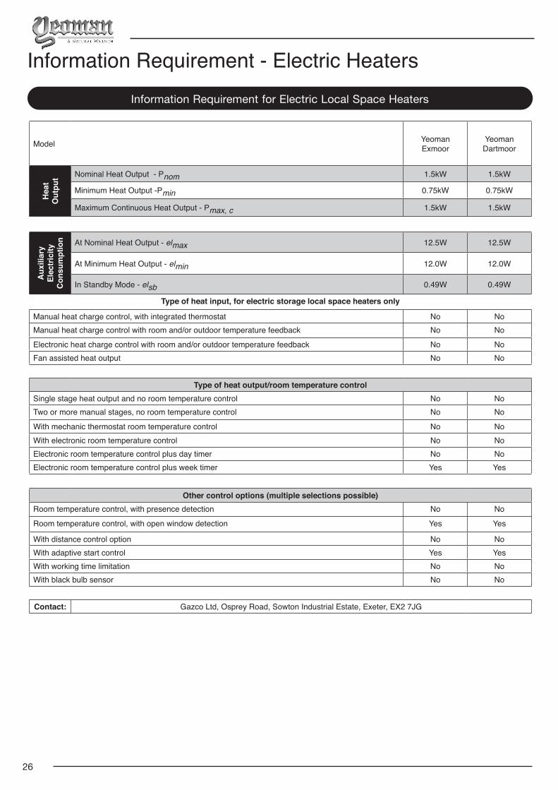
Information Requirement for Electric Local Space Heaters
Information Requirement - Electric Heaters
Model Yeoman Exmoor
Yeoman Dartmoor
Hea
tO
utpu
t Nominal Heat Output - Pnom 1.5kW 1.5kW
Minimum Heat Output -Pmin 0.75kW 0.75kW
Maximum Continuous Heat Output - Pmax, c 1.5kW 1.5kW
Aux
iliar
y El
ectr
icity
C
onsu
mpt
ion At Nominal Heat Output - elmax 12.5W 12.5W
At Minimum Heat Output - elmin 12.0W 12.0W
In Standby Mode - elsb 0.49W 0.49W
Type of heat input, for electric storage local space heaters only
Manual heat charge control, with integrated thermostat No NoManual heat charge control with room and/or outdoor temperature feedback No No
Electronic heat charge control with room and/or outdoor temperature feedback No NoFan assisted heat output No No
Type of heat output/room temperature controlSingle stage heat output and no room temperature control No NoTwo or more manual stages, no room temperature control No No
With mechanic thermostat room temperature control No NoWith electronic room temperature control No NoElectronic room temperature control plus day timer No NoElectronic room temperature control plus week timer Yes Yes
Other control options (multiple selections possible)Room temperature control, with presence detection No No
Room temperature control, with open window detection Yes Yes
With distance control option No NoWith adaptive start control Yes YesWith working time limitation No NoWith black bulb sensor No No