Lab 8 Comparator, and Decoder circuits OBJECTIVES 1. Understanding the construction and operational principles of digital comparators and decoders. BACKGROUND Comparator circuits: At least two numbers are required to perform any comparison. The most simple form of comparator has two inputs. If the two inputs are called A and B there are three possible outputs : A>B; A=B; A<B. Fig. 5-1 shows the schematic and symbol of a simple comparator. A 1-bit comparator is shown in Fig. 5.1 In actual applications 4-bit comparators are used most often. 4-bit comparator ICs that determine greater or less inputs include TTL 7485 and CMOS 4063. TTL 74689 is an IC that only compares whether the Inputs are equal. In a 4-bit comparators, each bit represents 2 0 , 2 1 , 2 2 , 2 3 . Comparisons will start from the highest bit (2 3 ), if input A is higher than input B at the 2 3 bit, the “A>B” output will be in high state. If A and B are equal at the 2 3 bit, comparison will be carried out at the next highest bit (2 2 ). If there is still no result at this bit the process is repeated again at the next 1 Fig. 5-1
Transcript
Lab 8
Comparator, and Decoder circuits
OBJECTIVES1. Understanding the construction and operational principles of digital
comparators and decoders.
BACKGROUND Comparator circuits:
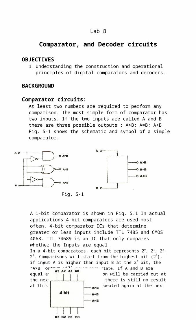
At least two numbers are required to perform any comparison. The most simple form of comparator has two inputs. If the two inputs are called A and B there are three possible outputs : A>B; A=B; A<B. Fig. 5-1 shows the schematic and symbol of a simple comparator.
A 1-bit comparator is shown in Fig. 5.1 In actual applications 4-bit comparators are used most often. 4-bit comparator ICs that determine greater or less inputs include TTL 7485 and CMOS 4063. TTL 74689 is an IC that only compares whether the Inputs are equal.In a 4-bit comparators, each bit represents 20, 21, 22, 23. Comparisons will start from the highest bit (23), if input A is higher than input B at the 23 bit, the “A>B” output will be in high state. If A and B are equal at the 23 bit, comparison will be carried out at the next highest bit (22). If there is still no result at this bit the process is repeated again at the next bit. At the lowest bit (20), if the inputs are still equal then the “A=B” output will be in high state.
1
Fig. 5-1
Fig. 5-1, symbol of 4-bit comparators
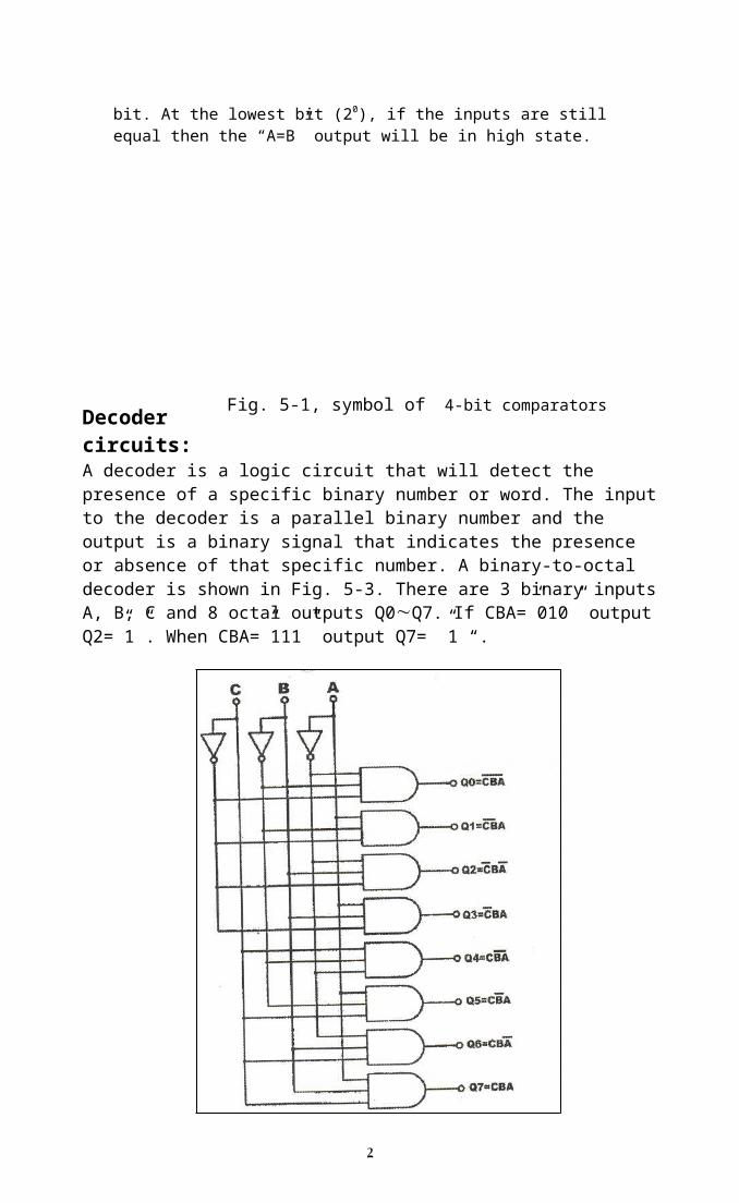
Decoder circuits:A decoder is a logic circuit that will detect the presence of a specific binary number or word. The input to the decoder is a parallel binary number and the output is a binary signal that indicates the presence or absence of that specific number. A binary-to-octal decoder is shown in Fig. 5-3. There are 3 binary inputs A, B, C and 8 octal outputs Q0Q7. If CBA=”010” output Q2=”1”. When CBA=”111” output Q7= ”1 “.
PRELAB:comparator1. Write down Boolean expression and truth table for 2 bit comparator shown in
fig.5.1.2. Use data sheet to draw the schematic (pin diagram) of the 7485 an 4-bit
comparator and write down its function table.Decoder3. Write down Boolean expression and truth table for each of the outputs
F1F4 in 2 by 4 decoder shown in fig.5.4.4. Use data sheet to draw the schematic (pin diagram) of the 74138 3by8 decoder
and write down its function table (given in the data sheet).
Part I: Comparator constructed with basic logic gates
a) Use model KL-33002 block C, insert connection clips in suitable places to construct a 1-bit comparator shown in fig.5.1.
b) Connect inputs A and B to data switches SW1 and SW2, connect outputs F1, F2, F5 to LEDs L1, L2, L3 respectively. Record the truth table of the circuit and compare with that in your prelab.
Part II: Comparator constructed with TTL IC
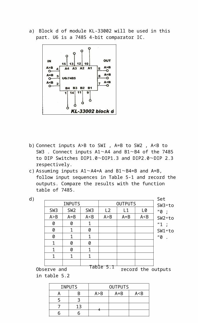
a) Block d of module KL-33002 will be used in this part. U6 is a 7485 4-bit comparator IC.
b) Connect inputs A>B to SWI , A=B to SW2 , A<B to SW3 . Connect inputs A1A4 and B1B4 of the 7485 to DIP Switches DIP1.0DIP1.3 and DIP2.0DIP 2.3 respectively.
c) Assuming inputs A1A4=A and B1B4=B and A=B, follow input sequences in Table 5-1 and record the outputs. Compare the results with the function table of 7485.
Part III: Constructing a 2-to-4 decoder with basic logic gates
a) Use model KL-33005 block C shown in fig.5.4.b) Connect inputs A and B to data switches SW0 and SW1, connect outputs
F1, F2, F3, F4 to LEDs L1, L2, L3 respectively.c) Follow the input sequences for A and B in table5.3 and record the output
states.
Part IV: 3 by 8 decoder circuit IC
a) Connect inputs A0, A1, and A2 to SW0, SW1, and SW2 respectively. Connect enables E1, E2, E3 to DIP1.0DIP1.2 respectively.
b) Verify the truth table of the 74138 you already have in your prelab.
Exercise: 1) Use 2 ICs 7485 to construct an 8-bit comparator. Show necessary
connections in a pin diagram for your design. Show each of the inputs A1A4 and B1B4 should be connected to which of the two ICs and which outputs should be connected to LEDs.
2) Draw 4 by 16 decoder by using two 3 by 8 decoders.