According to Part 91.519 requirements, the pilot-in-com-mand (PIC) or a crewmember briefs passengers on smoking,use of safety belts, location and operation of passenger entrydoor and emergency exits, location and use of survivalequipment, and normal and emergency use of oxygen equip-ment. For flights over water, the briefing should include ditch-ing procedures and the use of flotation equipment.
An exception to the oral briefing rule is if the pilot-in-com-mand determines passengers are familiar with the briefingcontent. A printed card with the FAR 91.519 required infor-mation should be available to each passenger to supplementthe oral briefing
Adjust seat fore and aft; the handle is below the forward cen-ter of the seat. Adjust seat vertically; the handle is on theaisle side forward corner. Ensure white ball is in the center ofthe orange ball on the seat adjustment indicator. Ensure seatbelt and shoulder harness are secure and snug. Adjust rud-der pedals. Depress the tab on the inboard side of the pedal,move the pedal forward or aft into one of the three positions,and then release the tab.
Oxygen pressure gage should read 1,600 to 1,800 PSI.Oxygen mask connection should be secure. Regulator shouldbe set to 100%. Ensure flow by donning the mask, adjustingthe fit, and breathing several times. On units 002 to 505, setPASS OXY VALVE and PRIORITY VALVE to normal. On unit550 and subsequent and SII, set OXYGEN CONTROLVALVE to normal.
CBs and Switches . . . . . . . . . . . CHECK LEFT/RIGHT
Generator Switches . . . . . GEN (OFF FOR EPU START)
Anti-Skid (C0 and CI [optional]; CII 001 to 436) . . . OFF
Anti-Skid (CII 437 and subsequent; SII) . . . . . . . . ON
Turn on anti-skid and complete self-test sequence prior totaxi (anti-skid annunciator extinguished) while the aircraft isstationary because if anti-skid system is turned on duringtaxi, the anti-skid sequence does not complete successfullyand anti-skid may not be operational during takeoff. If anti-skid is off prior to or during taxi, turn it on prior to takeoff.
Ensure power to Emergency bus items:� cockpit flood lights� COMM 1� NAV 2� copilot’s HSI (mechanical or single EFIS)� copilot’s attitude indicator (unit 627 and subsequent,
single EFIS)� directional gyro 2 (single EFIS)� copilot’s RMI (dual EFIS)� NAV 2 repeater (dual EFIS)� directional gyro 1 (dual EFIS)� audio panel (unit 627 and subsequent).
(SII) No longer than five seconds and no repeat within 10minutes in the W/S TEMP/ICE DETECT position
Rotate the TEST switch (CII; unit 627 and SII, except stick-shaker) to each of the following positions and verify the prop-er response:
� OFF – red light above rotary test switch extinguishes andtest system is inoperative.
� FIRE WARN – both ENGINE FIRE PUSH annunciatorsilluminate.
� LDG GEAR – three green safe and red GEARUNLOCKED annunciators illuminate; the gear hornsounds. Check that the horn silences by pressing the hornsilence button on the landing gear panel. The horn can besilenced only if the flap position is 15° or less (20° SII).
� BATT TEMP – BATT O’TEMP annunciator flashes and bat-tery temperature gage shows 160° to demonstrate circuitintegrity. MASTER WARNING annunciator also illumi-nates. Cancel MASTER WARNING by pressing annuncia-tor.
� STICK SHAKER (SII) – the angle of attack indicator drivesto zero and the flag appears. The flag disappears and theindicator moves to 1.0. As the indicator moves, the EADIfast/slow indicator and the AOA indexer (if installed) shouldcorrespond to indicator position. At approximately 0.75 thestick shaker activates for a few seconds. This cycle repeatsas long as the rotary test switch remains in this position.
2B-8 For training only Citation I/II/SIIJune 1997
� T/REV – the left and right ARM, LOCK, and DEPLOYannunciators illuminate and the MASTER WARNINGannunciator flashes. Cancel MASTER WARNING by press-ing annunciator.
� W/S TEMP/ICE DETECT (SII) – The W/S AIR O’HEATannunciator illuminates when LOW or HIGH is selected onthe windshield bleed air switch. ICING DETECTED annun-ciator illuminates for approximately one minute.
� W/S TEMP – the W/S AIR O’HEAT annunciator illuminateswhen the windshield bleed air switch is selected to HIGH orLOW
� OVER-SPEED – the audible overspeed warning sounds� ANTI-SKID – the anti-skid system initiates a self-test. ANTI-
SKID INOP annunciator illuminates and remains illuminatedfor three or four seconds after the test switch is placed inOFF. The annunciator extinguishes if the system checksoperational. If the system fails the check, the annunciatorremains illuminated.
� ANNU – all annunciators and the MASTER WARNINGannunciators illuminate. The turbine speed indicator selftests with its red lights illuminating and the displays flashingall eights (888). When the avionics power switches are on,the altitude alert and autopilot/flight director mode selectorpanel lights illuminate. EFIS and FMS lights also illuminate.The MASTER WARNING annunciators cannot be resetwhile the rotary selector switch is in this position.
CAUTION: (SII) The ice detection system probe maybe damaged if the test selector switch remains in theW/S TEMP/ICE DETECT position longer than five sec-onds and/or repeated tests are performed within a 10-minute time period.
Momentarily pressing the START button begins enginerotation by closing the start relay. When the relay closes, theSTART button illuminates white and the ignition systemthen arms for actuation. The engine instrument floodlightand the associated FUEL BOOST ON annunciator illumi-nate. The FUEL LOW PRESS annunciator extinguishes asboost pump pressure increases.
Lift the cutoff latch and advance the throttle to IDLE. Fuelflow initiates and the ignition system activates. The associ-ated ignition light illuminates.
The engine start cycle terminates at approximately 38% N2.The START button light, ignition light, instrument floodlights,and FUEL BOOST ON annunciator extinguishes. If theGEN switch is in the GEN position, the GEN OFF annunci-ator extinguishes when generator output voltage exceedsbattery voltage.
If automatic start sequencing does not terminate, the FUELBOOST ON annunciator and ignition and associated lightsremain illuminated. At 38% N2, the speed sensor discontin-ues motoring the starter/generator. Depress the STARTERDISENGAGE button to terminate the automatic startsequence.
For a cross generator start, wait until turbine RPM reaches49 to 50% N2 and the generator is on line. Start the secondengine. Both starter buttons illuminate during a cross gener-ator start. A cross generator start reduces battery heat byeliminating a charging cycle.
For an external power start, both generator switches must beoff until start is complete. Do not turn on any electrical equip-ment until both GEN OFF annunciators are extinguished.The Citation II/SII has an overcurrent and overvoltage pro-tection system for GPU usage.
CAUTION: Turbine speed greater than 50% N2 on theoperating engine produces a generator output that maydamage the generator drive during the second enginestart.
2B-12 For training only Citation I/II/SIIJune 1997
Inverter Switch . . . . . . . . . . . . INVERT 1 OR 2 OR AC
Aircraft equipped with single bus AC system:
Move the inverter switch to INV 1/INV 2. Check that the ACFAIL annunciator is off in both positions. The switch may beleft in either position.
C0 001 to 274: Turn on the No. 2 inverter; the RAD AC PWRFAIL annunciator extinguishes. Move the crossover switch toXOVERl F/D AC PWR FAIL annunciator extinguishes andRAD AC PWR FAIL annunciator illuminates. Turn on the No. 1inverter; RAD AC PWR FAIL annunciator extinguishes. MoveXOVER switch back to NORM; both annunciators remainextinguished.
Engine anti-ice is required when operating in icing conditions.For ground operation in icing conditions, the ENG ANTI-ICEfail annunciators must be extinguished for a minimum of oneminute out of four (with the engine anti-ice switches ON).
CAUTION: Limit ground operation of pitot/static heat to twominutes to prevent damage to the angle-of-attack system.
NOTE: When operating in visible icing conditions withOAT (CII -30°C (-22°F) to 40°C (40°F), SII -30°C to10°C), ensure that pitot/static and engine anti-ice is onand operating.
Expanded Normal Procedures
Citation I/II/SII For training only 2B-15June 1997
Check TKS anti-ice system prior to takeoff if flight intoicing conditions is expected. Observe that fluid exudesfrom all visible wing panels; associated anti-ice lightsextinguish.
If the temperature is above -18°C, turn the windshield bleedair switch to LO. If temperature is -18°C or below, turn thewindshield bleed air switch to HI.
CAUTION: Do not operate deice boots when the ambi-ent air temperature is below -40°C (-40°F).
2B-16 For training only Citation I/II/SIIJune 1997
Extend flaps to LAND then set for takeoff and check indicatormovement. (SII) – Check that the HYD PRESS ON annunci-ator illuminates when the flap handle is moved. Verify flap triminterconnect operation between 10 and 25°. Retract flaps toT.O. & APPR (20°) or to T.O. (7°) as appropriate.
Check that the HYD PRESS ON annunciator illuminatesuntil speedbrakes are extended. The annunciator extin-guishes when the SPD BRAKE EXTENDED annunciatorilluminates. Observe upper speedbrake panels extension.
Check that the HYD PRESS ON annunciator illuminatesand then extinguishes and the SPD BRAKE EXTENDEDannunciator extinguishes. Visually check that the upperspeedbrake panel stows properly.
Selecting the INV 1 position turns off the No. 1 inverter andilluminates the INVERTER FAIL NO. 1 annunciator. The ACFAIL and MASTER WARNING annunciators should illumi-nate. Press the MASTER WARNING annunciator and notethat the MASTER WARNING and AC FAIL annunciatorsextinguish. Confirm EFIS is still operational (AC poweredby No. 2 inverter).
Selecting the INV 2 position turns off the No. 2 inverter andilluminates the INVERTER FAIL NO. 2 annunciator. The ACFAIL and MASTER WARNING annunciators should illumi-nate. Press the MASTER WARNING annunciator and notethat the MASTER WARNING and AC FAIL annunciatorsextinguish. Confirm EFIS (dual EFIS configuration) is stilloperational (AC powered by No. 1 inverter).
The AUTOPILOT OFF annunciator illuminates and theautopilot warning horn sounds for one second. On CII 163and subsequent and SII, the AP TORQUE annunciatorilluminates.
Move the heading cursor to the left or right of lubberline. Note that the control wheel follows.
Expanded Normal Procedures
Citation I/II/SII For training only 2B-19July 1999
Flight Director ALT Mode . . . . . . . . . . . . . SELECT
Adjust pilot’s altimeter by changing the altimeter settingin the Kollsman window. With a lower altitude selectedon the pilot’s altimeter, the control column moves aft.After selecting a higher altitude the control columnmoves forward.
Flight Director ALT Mode . . . . . . . . . . DISENGAGE
Check that the ARM and UNLOCK annunciators illuminateand the DEPLOY annunciator illuminates within 1.5 sec-onds of the UNLOCK annunciator illuminating.
CAUTION: If, during taxiing, a hard brake pedal/no brak-ing condition occurs, turn anti-skid off. If brakes are still notoperational, operate the emergency brake system.Maintenance is required before flight.
CAUTION: Do not attempt to fly the aircraft if the thrustreverser preflight test is unsuccessful.
2B-22 For training only Citation I/II/SIIJune 1997
If the source selector is left in GND, excessive air extractionoccurs on the right engine and the engine does not developfull takeoff thrust and ACM OVERPRESS warning light mayilluminate
Cabin Temperature Control . . . . . . . . . . . . . . AUTO
The ACM over-temperature protection circuit operates only inthe AUTOMATIC mode.
Anti-Skid (When Stopped) (Units 002 to 436) . . . . . . ON
Turn on pitot/static heat and engine anti-ice (use W/S bleed airanti-ice as required) when operating in visible moisture at thefollowing outside air temperatures:
C0; CI; CII; CII-627 and sub. . . . . . . . . . . . 4 to -30°C
For flights 30 minutes before sunset to 30 minutes after sun-rise, turn on navigation lights. Do not operate anti-collisionlights in fog, clouds, or haze. The light beam reflection cancause disorientation or vertigo.
Radar (Unit 627 and Subsequent) . . . . . . . . . . . . . ON
Radar switch is in ON but radar remains in standby with aircraftweight-on-wheels (squat switch protection). Simultaneously,pressing both range buttons on the radar control panel over-rides squat switch protection.
All annunciators extinguish (except ENG ICE FAIL if that sys-tem is selected with low power). The ACM EJECTOR ONannunciator (CII 001 to 484) may illuminate if the pressuriza-tion source selector is in a position other that OFF or EMER.The flight director should be in GO AROUND with HeadingAltitude Select functions selected.
When a positive rate-of-climb is indicated, pull the gear han-dle out and move it to the UP position to begin the retractioncycle. Handle movement illuminates the GEAR UNLOCKEDand HYD PRESS ON annunciators. Check that both annunci-ators extinguish to indicate the landing gear is up and locked.
At a comfortable altitude with the wings level and a minimumairspeed of V2 +10, depress the flap handle to clear thedetent then move full forward. Check that the position indi-cator to the left of the handle moves to the FLAPS UP posi-tion. On the SII, the HYD PRESS ON annunciator shouldremain illuminated any time the flaps are in transit and extin-guish when they reach the selected position.
With N1 speeds matched within 1.5% or N2 speeds matchedwithin 1%, place the engine synchronizer selector in FAN orTURB. Check that the engine instruments remain within nor-mal operating limits. Selecting FAN synchronizes the left andright fan (N1) speeds resulting in a quieter passenger cabinwhile selecting TURBINE matches left and right engine tur-bine (N2) speeds resulting in a quieter cockpit.
Pressurization/Cabin Temperature . . . . . . CHECK/SET
The controller was programmed before taxi. Adjust the rateknob to achieve a comfortable cabin rate-of-climb (usuallybetween 300 and 500 FPM). Observe differential pressure/cabin altitude and cabin vertical speed indicators.
Select anti-ice systems on as required for climb. Use ofengine anti-ice reduces allowable fan speed and dictatesclose monitoring of ITT and RPM limitations.
C0; CI; CII; CII-627 and sub. . . . . . . . . . . . 4 to -30°C
Place the passenger advisory switch in SEAT BELT to keepthe FASTEN SEAT BELT sign illuminated and extinguish theNO SMOKING and emergency exit lights. If no turbulence isexpected, place the switch in OFF to extinguish the FASTENSEAT BELT sign and emergency exit lights.
Turn Freon air conditioning off to prevent compressor motorand generator brushes arcing.
Cabin Temperature (by FL 310)(Units 482, 485 and subsequent; SII) . . . . . . . . . AUTO
Selecting AUTO above 31,000 ft reduces the possibility of anACM overheat and normally maintains a comfortable cabintemperature. With low airspeed and high power settings, anACM overheat is possible with an excessively cold setting inMANUAL.
Maintain climb thrust until attaining the desired cruise speed.If engine RPM does not automatically synchronize at thedesired cruise setting, turn engine synchronization OFF. Thisallows the synchronizer actuator to center. Roughly synchro-nize the engines with throttles and place the engine synchro-nizer switch in FAN or TURB.
Reset cabin altitude and/or rate as required. Maintain theTEMPERATURE CONTROL knob in the 12 to 2 o’clock posi-tion for a comfortable cabin temperature.
Check oxygen system pressure and masks:
� above FL 250 masks must be ready in their “quick-don-ning” position
� above FL 350 with only one pilot in the cockpit, that pilotmust be wearing oxygen mask
� above FL 410 at least pilot must wear an oxygen mask.
Expanded Normal Procedures
Citation I/II/SII For training only 2B-29June 1997
Turn on pitot/static heat and engine anti-ice (use W/S bleedair anti-ice as required) whenoperating in visible moisture atthe following outside air temperatures:
C0; CI; CII; CII-627 and sub. . . . . . . . . . . . 4 to -30°C
C0; CI; CII; CII-627 and sub.: Check deice system for prop-er operation prior to entering possible icing environment.
CAUTION: Do not operate deice boots when indicatedOAT is below -40°C (-40°F).
WARNING: SII – The surface fluid anti-ice system is nota deice system and does not remove significant accu-mulations of ice. Turn on the system immediately upondetecting ice. If more than 1/8 inch of ice accumulatesprior to turning the system on, leave the icing environ-ment.
2B-30 For training only Citation I/II/SIIJuly 1999
Turn on the DEFOG fan and close the foot warmers approxi-mately 15 minutes before descent to reduce condensation onthe windshield and cockpit side windows.
Closing foot warmers increases the flow of air available forwindshield defogging and isolates dry conditioned air betweenthe cockpit side windows to inhibit condensation formation.
After beginning descent, set destination field pressure altitude+200 ft on the controller CABIN dial. Monitor differential pres-sure/cabin altitude and cabin vertical speed indicators.
Windshield Bleed Air Switch/Manual Valves . . . LOW/MAX
Windshield bleed air can be used to externally warm the wind-shield in extreme conditions. Normally, the W/S BLEED switchLOW position provides adequate temperature.
A minimum of 65% N2 is required to keep the engine anti-icesystem operating properly. When operating in visible moisturewith indicated OAT (-30°C (-22°F) to 10°C (40°F); SII -30°C to10°C), ensure pitot/static and engine anti-ice is on and oper-ating. Use windshield bleed air as required.
(Recommended when the temperature/dewpoint spread isless than 5°C.)
Expanded Normal Procedures
Citation I/II/SII For training only 2B-31June 1997
When cleared below or passing through the transition altitude,set the reported or landing field barometric pressure on bothaltimeters. Cross-check settings.
Flaps may be extended to T.O. & APPR below 202 KIAS (200KIAS SII). Check indicator to verify position.
Pressurization . . . . . . . . . . . . . . SET FOR LANDING
Check that cabin differential pressure is near zero. If stillexcessive, adjust rate so the cabin ascends. If landing above12,000 ft pressure altitude, turn the OXYGEN CONTROLVALVE to CREW ONLY and the PRESS SOURCE selectorto OFF to prevent passenger oxygen mask deployment.
2B-34 For training only Citation I/II/SIIJuly 1999
Pull the landing gear handle out then move to DOWN. Whilethe gear is extending, the HYD PRESS ON and GEARUNLOCKED annunciators illuminate. When the landing gearreaches the down and locked position, the three green gearlights illuminate and the HYD PRESS ON and the red GEARUNLOCKED light extinguishes.
Approximately 500 ft above ground level, check that the cabindifferential pressure is near zero. If it is in excess of 0.5 PSID,select a higher cabin altitude and adjust RATE so the cabinascends. Differential pressure should be at zero for landing; attouchdown, any existing pressure is dumped.
If landing above 12,000 ft pressure altitude, turn the OXYGENCONTROL VALVE to CREW ONLY and bleed air to OFF topreclude passenger mask deployment.
Flaps may be extended to LAND below 176 KIAS (172 KIASSII). Depress the flap handle the move it to the LAND position.Ensure flap indicator moves to correspond with handle posi-tion. The HYD PRESS ON annunciator should illuminatewhenever the flaps are moving.
Depress the AP/TRIM DISC switch on either control wheel.With the yaw damper off, the pilot has complete rudder author-ity and nosewheel steering for landing.
Speedbrakes . . . . . . . . . . . RETRACT PRIOR TO 50 FT
The aircraft is not certified to land with speedbrakes extended.
Expanded Normal Procedures
Citation I/II/SII For training only 2B-35July 1999
Suggested crosswind technique involves flying a crab downfinal approach and aligning the longitudinal axis of the aircraftto runway centerline with the rudder just before touchdown.The wide expanse of cockpit visibility makes small crab anglesdifficult to detect; therefore, devote particular attention to thisarea to achieve smooth crosswind landings.
Touchdown, preceded by a slight flare, should occur on themain wheels. Check thrust at idle and extend speedbrakeswhile lowering the nose wheel.
CAUTION: If, during taxiing, a hard brake pedal/nobraking condition occurs, turn anti-skid off, operate theemergency brake system. Maintenance is requiredbefore flight.
CAUTION: Anti-skid protection is not available below12 kts groundspeed.
2B-36 For training only Citation I/II/SIIJuly 1999
Thrust Reversers (After Nose Wheel On Ground) . . . . . . . . . . . DEPLOY
Apply wheel brakes and deploy the thrust reversers. The air-craft pitches slightly upward during deployment; therefore, useslight nosedown elevator pressure during thrust reverserdeployment, especially at high speeds such as a refused take-off or no-flap landing.
The nose wheel must be on the ground before actuation of thethrust reversers to reduce the possibility of pitch-up and lift-offand to improve directional control. Do not exceed approxi-mately 15 lbs of force on the thrust reverser levers duringdeployment to prevent jamming of the throttle lockout cams.
Do not exceed 79% N1 when OAT is below -18°C or 86% N1
at or above -18°C. Once the thrust reversers are deployed,move the levers aft to maximum reverse thrust. Stops on thelevers provide 86% N1 on a -18°C day at sea level so the pilotcan keep his attention on the landing rollout. The factory set-ting results in lower than 86% N1 at warmer temperatures andmay be reset for higher N1 if temperatures are predominantlywarmer. Do not exceed 86% N1.
CAUTION: Do not use the thrust reversers for touchand go landings; a full stop landing must be madeonce the reversers are selected.
Expanded Normal Procedures
Citation I/II/SII For training only 2B-37December 1998
With the thrust reverser levers in the IDLE REVERSE detent,leave the reversers deployed for aerodynamic drag.Commence thrust reversing and braking according to runwaylength. With excess runway, normally begin braking afterthrust reverser deceleration is below 60 knots.
Use caution on runways with small loose gravel that may beingested in the engine at idle reverse at low taxi speed.
CAUTION: Do not advance throttles until the reverserUNLOCK annunciators extinguish. There is danger ofthe throttle being rapidly returned to idle position,which could cause injury.
CAUTION: Do not use the thrust reverser for morethan 15 minutes out of each hour.
2B-38 For training only Citation I/II/SIIJune 1997
After LandingAccomplish this checklist after the aircraft is clear of the runway.
On the SII, check that the HYD PRESS ON annunciatorextinguishes after the flaps are up. Taxiing with flaps extend-ed on a snow- or slush-covered taxiway could result inobstruction of the flaps.
W/S BLEED AIR may be used as required in falling precipi-tation. Turn engine anti-ice ON and operate the engines at orabove 65% N2 for a minimum of one minute out of every fourminutes if taxiing in visible moisture with temperaturesbetween +10 and -30°C. Ensure the PITOT & STATIC switchis off.
Do not set the parking brake if brakes are very hot. This canincrease heat transfer from the brakes to the wheel, causingthe fusible plug to melt and deflate the tire.
Allow ITT to stabilize for at least one minute at minimum value.Lifting the latch and placing the throttle full aft terminates fuelflow to the engine combustion section. A canister collectsmanifold fuel on shutdown. During the next engine start, thisfuel returns to the fuel cell. Repeated starts for ground opera-tions cause the canister to overflow through the lower nacelleafter the third shutdown.
C0 001 to 213 without SB71-2: A canister collects manifoldfuel on shutdown and vents it into the atmosphere during thenext flight.
C0 001 to 213 with SB71-2: The crew drains the canisterthrough a manual valve. Repeated starts for ground operationcause the canister to overflow through the lower nacelle afterthe third shutdown.
Exercise care not to place it in EMER. Emergency bus itemswill drain the battery over an extended period.
For deplaning at night, leave the battery switch in BATT forcabin lighting until passengers and cabin baggage aredeplaned. Turn the EXTERIOR WING INSP LIGHTS switchto ON to provide additional illumination in front of the cabindoor. An illuminated courtesy light switch on the forward doorpost is wired to the Hot Battery bus to turn on the emergencyexit lights and one aft cabin baggage compartment light.
Citation I/II/SII For training only 2B-41June 1997
Expanded Normal Procedures
ParkingPark the aircraft facing a direction that facilitates servicing.Under normal circumstances, the prevailing wind can be dis-regarded.
Aircraft . . . . . . . . . PARK ON HARD, LEVEL SURFACE
Foul Weather Windowand Door . . . . . . . . . . . . . . CLOSE AS NECESSARY
2B-42 For training only Citation I/II/SIIJune 1997
Mooring
If extended parking plans or impending weather necessitatesmooring the aircraft, attach 3/4-inch ropes (or equivalent sub-stitute) to the nose and main gear struts; this procedurerequires tie-down eyelets set into the apron. There is no proce-dure for mooring at unprepared facilities.
Aircraft . . . . . . . . . PARK ON HARD, LEVEL SURFACE . . . . . . . . . . . . . . . . . .AND HEAD INTO THE WIND
Foul Weather Windowand Door . . . . . . . . . . . . . . CLOSE AS NECESSARY
CAUTION: Ensure ropes do not contact sharp edgesand do not damage equipment.
Citation I/II/SII For training only 2B-43June 1997
Expanded Normal Procedures
Towing/TaxiingThe aircraft taxies on hard, gravel, or sod surfaces. On hardsurfaces, tow with a yoke-type tow bar attached to the nosegear. When not on hard surface (such as sand, soft ground, ormud), attach cables or ropes to each main gear for towing andsteer the aircraft with rudder pedals.
Towing or taxiing aircraft with a flat tire is not recommended.However, if a situation requires it, tow or taxi the aircraft forwardjust enough to clear the immediate area (Figures 2B-1, 2B-2,2B-3, and 2B-4, following pages). If towing, avoid sharp turns.Observe aircraft turning distances.
2B-44 For training only Citation I/II/SIIJune 1997
22.05 FT
6.58 FT15.85 FT
WALL TO WALL 43.91 FT (C0) 47.08 FT (CI)
CURB TO CURB22.16 FT
21.86 FT (C0)23.54 FT (CI)
2B-1
Towing DistancesCitation; Citation I
Expanded Normal Procedures
Citation I/II/SII For training only 2B-45February 2001
16.83 FT
13.16 FT
CURB TO CURB30.00 FT
WALL TO WALL 56.88 FT (C0) 59.88 FT (CI)
2B-2
Taxiing DistancesCitation; Citation I
2B-46 For training only Citation I/II/SIIFebruary 2001
Towing the aircraft with the controls locked may place exces-sive force on the control lock mechanism and the rudder con-trol cables. Avoid towing the aircraft with the control lockengaged. If the aircraft is towed with control lock engaged,limit the nosewheel turning angle to approximately 60° to pre-vent unnecessary loads on the control system. When extremeturning angles are required, release the control lock system.
CAUTION: Do not move the aircraft within 15 minutesafter gyros have been shut down or damage to thegyros may occur.
TOWING LIMITATION: Maximum nose gear towingturning angle limit is 95° either side of center. Forcingthe nose gear beyond the towing stop (95° limit) shearsthe bolts attaching the steering gear assembly to thecylinder.
Citation I/II/SII For training only 2B-49June 1997
Attach cables to towing adapters and towing vehicle. Use careto prevent crushing wiring or linkage rods in the wheel wellarea. Verify that the cable length clears the aircraft and that thetowing vehicle is on a hard surface.
Tow Cables and Towing Adapters . . . . . . . . . REMOVE
2B-50 For training only Citation I/II/SIIJune 1997
NOTE: Aircraft equipped with power brakes/anti-skid mustuse power brakes with battery on.
Citation I/II/SII For training only 2B-51June 1997
Expanded Normal Procedures
Citation I/II/SII For training only
Taxiing (Ground Movement)During taxi, control the aircraft via selected engine thrust, rud-der pedal steering, and brakes. Taxiing can be performed withone or both engines operating.
Citation I/II/SII For training only 2B-55December 1998
Cold Weather Operations
Ground Deice/Anti-Ice OperationsDuring cold weather operations, flight crews are responsible forensuring the aircraft is free of ice contaminants.
Ground icing may occur at temperatures of +10°C or colderwith high humidity. To comply with FAA regulations (clean wingconcept) requiring critical component airframe deicing andanti-icing, Type I deice fluids and Type II anti-ice fluids can beused sequentially.
The pilot-in-command (PIC) or second-in-command (SIC)should supervise line personnel to ensure proper application ofeither fluid.
Deicing Supplemental InformationThis section provides supplementary information on aircraftdeicing, anti-icing/deicing fluids, deicing procedures, and air-craft operating procedures. Consult the AFM, MaintenanceManual Chapter 12 – Servicing, and FAA Advisory Circulars fordeicing procedures, holdover times, fluid specifications, recom-mendations, and hazards.
Federal Aviation Regulations (FARs) prohibit takeoff withsnow, ice, or frost adhering to the wings and control surfacesof the aircraft.
CAUTION: Type I and Type II fluids are not compatibleand may not be mixed. Additionally, most manufacturersprohibit mixing of brands within type.
NOTE: Flight crews should refamiliarize themselves sea-sonally with Cessna Maintenance Manual Chapter 12 andFAA Advisory Circular AC120-58, dated September 9,1992 or later, for expanded deice and anti-ice procedures.
Expanded Normal Procedures
2B-56 For training only Citation I/II/SIIDecember 1998
Federal Aviation Regulations (FARs) prohibit takeoff withsnow, ice, or frost adhering to the wings and control surfacesof the aircraft.
It is the responsibility of the pilot-in-command to ensure the air-craft is free of snow, ice, or frost before takeoff.
Failure to adequately deice the aircraft can result in seriouslydegraded aircraft performance, loss of lift, and erratic engineand flight instrument indications.
Following extended high-altitude flight, frost can form at ambi-ent temperatures above freezing on the wing’s underside in thefuel tank areas. Refueling the aircraft with warmer fuel usuallymelts the frost.
Deicing
When necessary, use the following methods to deice the aircraft:� placing the aircraft in a warm hangar until the ice melts� mechanically brushing the snow or ice off with brooms,
brushes, or other means� applying a heated water/glycol solution (one-step procedure)� applying heated water followed by an undiluted glycol-based
fluid (two-step procedure).
Deicing FluidsTwo types of anti-icing/deicing fluids are in commercial use:SAE/ISO Types I and II. Type I fluids are used generally inNorth America. Type II fluids, also referred to as AEA Type II,are used generally in Europe.
Type I fluids are unthickened glycol-based fluids that are usu-ally diluted with water and applied hot; they provide limitedholdover time.
Type II fluids are thickened glycol-based fluids that are usuallyapplied cold on a deiced aircraft; they provide longer holdovertimes than Type I fluids.
Citation I/II/SII For training only 2B-57December 1998
Expanded Normal Procedures
NOTE: Holdover time is the estimated time that an anti-icing/deicing fluid protects a treated surface from ice orfrost formation.
CAUTION: Type II FPD generally should not be appliedforward of the wing leading edges. If used for deicing, donot apply forward of cockpit windows. Ensure that radomeand cockpit windows are clean.
Many factors influence snow, ice, and frost accumulation andthe effectiveness of deicing fluids. These factors include:
� ambient temperature and aircraft surface temperature� relative humidity, precipitation type, and rate� wind velocity and direction� operation on snow, slush, or wet surfaces� operation near other aircraft, equipment, and buildings� presence of deicing fluid and its type, dilution strength, and
application method.
Holdover TimesHoldover timetables are only estimates and vary depending onmany factors, which include:
Holdover times are based on mixture ratio. Times start whenthe last application has begun. Guidelines for holdover timesanticipated by SAE Type I or Type II and ISO Type I or Type IIfluid mixtures are a function of weather conditions and outsideair temperature (OAT).
The freezing point of either type of fluid mixture must be atleast 10°C (18°F) below OAT.
2B-58 For training only Citation I/II/SIIDecember 1998
CAUTION: If engines are running when spraying of deic-ing fluids is in progress, turn bleed air and air conditioningpacks off.
Deicing ProceduresOne-step deicing involves spraying the aircraft with a heated,diluted deicing/anti-icing fluid to remove ice, snow, or frost. Thefluid coating then provides limited protection from further accu-mulation.
Two-step deicing involves spraying the aircraft with hot water ora hot water/deicing fluid mixture to remove any ice, snow, orfrost accumulation followed immediately by treatment with anti-icing fluid (usually Type II FPD fluid).
Deice the aircraft from top to bottom. Avoid flushing snow, ice,or frost onto treated areas. Start the deicing process by treat-ing the horizontal stabilizer followed by the vertical stabilizer.Continue by treating the fuselage top and sides. Finally, applydeicing fluid to the wings.
CAUTION: Do not use deicing fluid to deice engines.Mechanically remove snow and ice from the engine inlet.Check the first stage fan blades for freedom of movement.If engine does not rotate freely, deice engine with hot air.
Deicing fluid should not be applied to:
� pitot/static tubes, static ports, temperature probes, AOAvanes, or TAT probe
� gaps between control surfaces and airfoil� cockpit windows� passenger windows� air and engine inlets and exhausts� vents and drains� wing and control surface trailing edges� brakes.
Citation I/II/SII For training only 2B-59December 1998
Expanded Normal Procedures
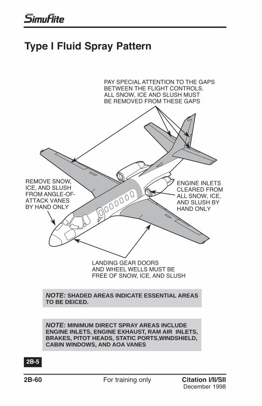
Spraying Technique – Type ISpray Type I fluid on the aircraft (with engines off) in a mannerthat minimizes heat loss to the air. If possible, spray fluid in asolid cone pattern of large coarse droplets at a temperature of160 to 180°F (Figure 2B-3, following page). Spray the fluid asclose as possible to the aircraft surfaces, but no closer than 10ft if using a high pressure nozzle.
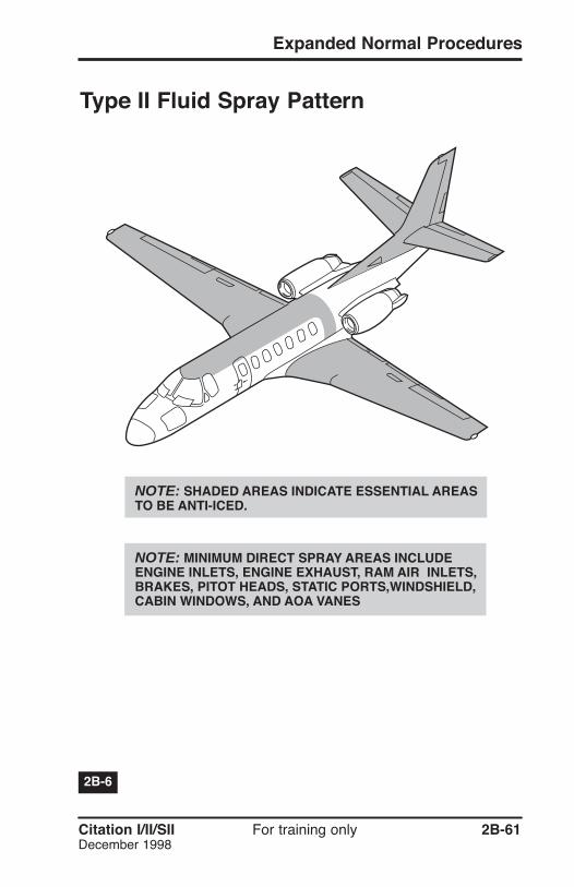
Spraying Technique – Type IIApply Type II fluid cold to a “clean” aircraft. It may also be heat-ed and sprayed as a deicing fluid; if so, consider it a Type I fluidbecause heat may change the characteristics of the thickeningagents in the fluid. When applied in this manner, Type II fluid isnot as effective as if it were applied cold.
Type II fluid application techniques are the same as for Type I,except that, because the aircraft is already clean, the applica-tion should last only long enough to properly coat aircraft sur-faces (Figure 2B-4, page 2B-53).
Pre-Takeoff Contamination CheckIn ground icing conditions, the PIC/SIC conducts a pre-take-off contamination check within five minutes of takeoff, prefer-ably just prior to taxiing onto the active runway. Critical areasof the aircraft (e.g., empennage, wing , windshield, controlsurfaces) must be checked to ensure they are free of ice,slush, and snow or that the deice/anti-ice fluids are still pro-tecting the aircraft.
2B-60 For training only Citation I/II/SIIDecember 1998
PAY SPECIAL ATTENTION TO THE GAPSBETWEEN THE FLIGHT CONTROLS.ALL SNOW, ICE AND SLUSH MUSTBE REMOVED FROM THESE GAPS
ENGINE INLETSCLEARED FROMALL SNOW, ICE,AND SLUSH BYHAND ONLY
LANDING GEAR DOORSAND WHEEL WELLS MUST BEFREE OF SNOW, ICE, AND SLUSH
REMOVE SNOW,ICE, AND SLUSHFROM ANGLE-OF-ATTACK VANESBY HAND ONLY
NOTE: SHADED AREAS INDICATE ESSENTIAL AREASTO BE DEICED.
NOTE: MINIMUM DIRECT SPRAY AREAS INCLUDEENGINE INLETS, ENGINE EXHAUST, RAM AIR INLETS,BRAKES, PITOT HEADS, STATIC PORTS,WINDSHIELD,CABIN WINDOWS, AND AOA VANES
2B-5
Type I Fluid Spray Pattern
Citation I/II/SII For training only 2B-61December 1998
Expanded Normal Procedures
NOTE: SHADED AREAS INDICATE ESSENTIAL AREASTO BE ANTI-ICED.
NOTE: MINIMUM DIRECT SPRAY AREAS INCLUDEENGINE INLETS, ENGINE EXHAUST, RAM AIR INLETS,BRAKES, PITOT HEADS, STATIC PORTS,WINDSHIELD,CABIN WINDOWS, AND AOA VANES
2B-6
Type II Fluid Spray Pattern
2B-62 For training only Citation I/II/SIIDecember 1998
PreflightDuring preflight preparation, inspect areas where surface snowor frost can change or affect normal system operations.Supplemental preflight checks include the following.
The wing leading edges, all control surfaces, tab surfaces,and control cavities must be free of frost, ice, or snow. Checkcontrol cavities for drainage after snow removal becausewater puddles may re-freeze in flight.
Pitot Heads And Static Ports . . . . . . .CLEARED OF ICE
Water rundown resulting from snow removal may re-freezeimmediately forward of the static ports. This causes an icebuildup that results in disturbed airflow over the static ports.The disturbed airflow can cause erroneous static readingseven though the static ports themselves are clear.
Engine preheating is best accomplished by installing theengine covers and directing hot air through the oil filleraccess door.
GPU StartIf aircraft is cold-soaked below -10°C, use a GPU and/or pre-heat procedure for starting.
Engine StartDuring cold weather starts, initial oil pressure may be slow inrising; the OIL PRESS WARN annunciator may remain illumi-nated longer than normal.
During cold weather starts, the oil pressure may temporarilyexceed maximum pressure limits until the oil temperaturerises. At low ambient temperatures, tolerate a temporaryhigh pressure above maximum limits, but delay takeoff untilthe pressure drops into normal limits.
During operation from snow-covered runways, turn onengine anti-ice during taxi and takeoff. Precede takeoff bya static engine run-up to as high a power level as practicalto ensure observation of stable engine operation prior tobrake release.
If severe icing conditions are present, turn on engine anti-ice immediately after engine start. During prolonged groundoperation, perform periodic engine run-up to reduce thepossibility of ice buildup. For sustained ground operation,operate the engines at a power setting high enough to extin-guish the engine anti-ice annunciators for one out of everyfour minutes.
2B-64 For training only Citation I/II/SIIDecember 1998
NOTE: With temperature -15°C or below, the windshieldheat rotary test may not function. The EFIS system mayrequire as long as 20 minutes to align.
Citation I/II/SII For training only 2B-65February 2001
Check for freedom of movement when the aircraft has beenexposed for an extended period of time to snow, freezingrain, or other conditions that can restrict flight control move-ment. Increased control forces can be expected at low tem-peratures because of the increased resistance in cables andthe congealed oil in snubbers and bearings. It may be desir-able to accomplish an additional control check prior to taxi.
Temperature Control . . . . . . . . . . . . . . . . . REDUCE
Reduce prior to takeoff.
Windshield Bleed Air . . . . . . . . . . . . . . . . LOW OR HI
Use windshield bleed air and defog fan to clear the windshield.
CAUTION: When operating the wing flaps during lowtemperatures, closely observe the flap position indicatorfor positive movement. Be ready to match the control leverwith the indicator if the flaps stop moving.
2B-66 For training only Citation I/II/SIIDecember 1998
Extend flaps to the takeoff setting at this time if they havebeen held because of slush or wet snow.
Before Takeoff Checklist . . . . . . . . . . . . . COMPLETETo ensure the aircraft is configured for takeoff, recheck theflap position indicator.
CAUTION: If flaps are left up during taxi to avoid slushand ice, complete the Before Taxi checklist after the flapsare in takeoff configuration.
CAUTION: Use extreme caution when taxiing on ice-cov-ered taxiways or runways because excessive speed orhigh crosswinds may start a skid. Make all turns atreduced speed.
Citation I/II/SII For training only 2B-67December 1998
Expanded Normal Procedures
TakeoffIf Engine Anti-Ice is Used for Takeoff:
Thrust . . . . . . . . USE ENGINE ANTI-ICE ON SETTINGS
V1 and Takeoff Field Length . . . . . . . . . . . ADJUST IN . . . . . . . . . . . . . . . . . . .ACCORDANCE WITH AFM
If Aircraft Slides on Ice or Snow During Engine Power Check:
Continue engine checks during the early part of the takeoffroll. On icy runways, expect a lag in nosewheel steering andanticipate corrections. A light forward pressure on the controlcolumn increases nosewheel steering effectiveness.
Use rudder and differential braking as necessary for direc-tional control. Reduce brake pressure if excessive anti-skidcycling creates directional control problems.
In Flight
Pitot Heat . . . . . . . . . ON FOR DURATION OF FLIGHT
Windshield Bleed Air . . . . . . . . . . . . . . . LOW OR HI
Use HI at -18°C (0°F) or below. For additional bleed air,increase the power setting with speedbrakes extended.
2B-68 For training only Citation I/II/SIIJuly 1999
CAUTION: If wing ice buildup is noticed, do not turnengine anti-ice on until wing ice erodes. Engine damagemay result.
CAUTION: Do not operate the surface deice boots withOAT below -40°C (-40°F) after long exposure to low tem-peratures unless absolutely necessary. Boot separationmay result.
Citation I/II/SII For training only 2B-69July 1999
During icing conditions, turn on engine anti-icing. During pro-longed ground operation, perform periodic engine run-ups toreduce the possibility of ice buildup. For ground operation,turn on the system one minute out of four with N2 set at 65%.
If icing conditions are present, leave engine anti-ice on fortaxi-in. During prolonged ground operation, perform periodicengine run-up to reduce the possibility of ice buildup. Forsustained ground operation, operate the engines at a powersetting high enough to extinguish the engine anti-ice annun-ciators for a minimum of one out of every four minutes.
Windshield Bleed Air . . . . . . . . . . . . . . . LOW OR HI
Use windshield bleed air and the defog fan to clear thewindshield.
Securing Overnight or for ExtendedPeriod (Aircraft Unattended)Wheel Chocks . . . . . . . . . . . . . CHECKED IN PLACE
If the ni-cad battery will be exposed to temperatures below -18°C (0°F), remove the battery and store in an area warmerthan -18°C (0°F) but below 40°C (104°F). Subsequent re-installation of the warm battery enhances starting capability.