1 ACCC ® is a Registered Trademark of CTC Global October 2013 Experience and Benefits of using High Temperature Low-Sag (HTLS) Overhead Conductors Tony Hill Vice President Business Development Europe [email protected]
Transcript
1 ACCC® is a Registered Trademark of CTC Global
October 2013
Experience and Benefits of using High Temperature Low-Sag
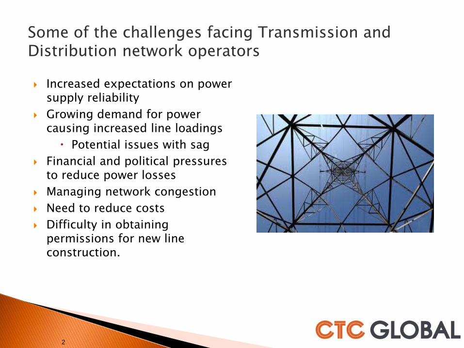
Some of the challenges facing Transmission and Distribution network operators
Increased expectations on power supply reliability
Growing demand for power causing increased line loadings
Potential issues with sag
Financial and political pressures to reduce power losses
Managing network congestion
Need to reduce costs
Difficulty in obtaining permissions for new line construction.
2
3
Traditional Overhead line conductor
◦ ACSR (Aluminum Conductor Steel Reinforced)
Over 100 years experience
As loads increase resistance increases causing increased losses
As loads increase conductor sag increases due to high Coefficient of Thermal expansion.
Expected life around 30 years - dependent upon loading, corrosive environment and quality
3
4
Aluminium
Standard Aluminium and Aluminium Alloys can only operate continuously at temperatures up to 93ºC
TAL and ZTAL aluminium have essentially the same conductivity and tensile strength as ordinary electrical conductor grade aluminium but can operate continuously at temperatures up to 150ºC and 210ºC, respectively.
Fully annealed aluminium is chemically identical to ordinary hard drawn aluminium and can operate indefinitely at temperatures at 250ºC (and higher) without any change in mechanical or electrical properties but has a much reduced tensile strength.
4
Annealed Aluminum is superior at high temperatures
Aerospace grade carbon fiber composite core offers greater strength and line loss reductions
ACCC®Carbon Composite Conductor
AluminumCarbon Fiber
Composite Core
ACSRSteel Core Conductor
Aluminum Stranded Steel
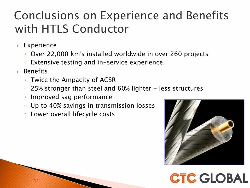
• ACCC® technology is based on replacing heavy steel core of traditional electrical transmission conductor with high strength, light weight carbon fiber composite core
• 28% More Aluminum = Greater Capacity, Reduced Losses, & Cooler Temps• 25% stronger and 60% lighter than a traditional steel core = fewer or lower structures• Lower Coefficient of Thermal Expansion = Less Sag at Higher Temperatures• Longer spans, fewer structures, increased line capacity• Applicable to all voltages• Resists degradation from vibration, corrosion, ultraviolet radiation, corona, chemical and
thermal oxidation and, most importantly, cyclic load fatigue
Perfect attributes for a conductor’s structural core
9
“Carbon fibers are not particularly
susceptible to fatigue damage. A
slight amount of alignment in the
fiber microstructure takes place
during fatigue, but fatigue lives -
at stresses as high as 98% of the
tensile strength - did not exhibit
fatigue failure.”
F-35/Joint Strike
Fighter (JSF)
10
ACCC
ACSR
12
Key Assumptions
•100km AC three phase Line
•Load factor 53%
•Peak current 1600 amps
Benefits – Reduction in losses
•Saving of some $3.6M per year in losses
•$3.39 loss saving per meter compared to ACSR
•$12.16 loss saving per meter compared to ACSS
•Reduced CO2 emissions
Investment in ACCC will significantly reduce losses
and provide higher IRR for projects
CTC Global CCP Software can calculate savings for your specific project
13
HTLS-ACCC Conductor Performance Stands
Alone
ACCC Conductors combine efficiency and increased current carrying capacity to deliver
more power with less losses based on equal conductor size and weight.
Amps per mm2
Current rating Amps
14
Moving on from benefits to experience
14
15
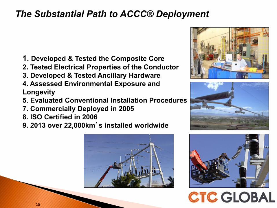
1. Developed & Tested the Composite Core
2. Tested Electrical Properties of the Conductor
3. Developed & Tested Ancillary Hardware
4. Assessed Environmental Exposure and
Longevity
5. Evaluated Conventional Installation Procedures
7. Commercially Deployed in 2005
8. ISO Certified in 2006
9. 2013 over 22,000km’s installed worldwide
The Substantial Path to ACCC® Deployment
Core Testing:
2.1.1 Tensile Testing2.1.2 Flexural, Bending & Shear Tests2.1.3 Sustained Load Tests2.1.4 Tg Tests2.1.5 CTE Measurements2.1.6 Shear Testing2.1.7 Impact and Crush Testing2.1.8 Torsion Testing2.1.9 Notched Degradation Testing2.1.10 Moisture Resistance Testing2.1.11 Long Term Thermal Testing2.1.12 Sustained Load Thermal Testing2.1.13 Cyclic Thermal Testing2.1.14 Specific Heat Capacity Testing2.1.15 High Temperature Short Duration 2.1.16 High Temperature Core Testing2.1.17 Thermal Oxidation Testing2.1.18 Brittle Fracture Testing2.1.19 UV Testing2.1.20 Salt Fog Exposure Tests2.1.21 Creep Tests2.1.22 Stress Strain Testing2.1.24 Micrographic Analysis2.1.25 Dye Penetrant Testing2.1.26 High Temperature Shear Testing2.1.27 Low Temperature Shear Testing
Mechanical Conductor Testing:
2.2.28 Stress Strain Testing2.2.29 Creep Testing2.2.30 Aeolian Vibration Testing2.2.31 Galloping Tests2.2.32 Self Damping Tests2.2.33 Radial Impact and Crush Tests2.2.34 Turning Angle Tests2.2.35 Torsion Tests2.2.36 High Temperature Sag Tests2.2.37 High Temperature Sustained Load 2.2.38 High Temperature Cyclic Load Tests2.2.39 Cyclic Ice Load Tests2.2.40 Sheave Wheel Tests2.2.41 Ultimate Strength Tests2.2.42 Cyclic Thermo-Mechanical Testing2.2.43 Combined Cyclic Load Testing2.2.44 Conductor Comparison Testing
Electrical Conductor Testing:
2.3.45 Resistivity Testing2.3.46 Power Loss Comparison Testing2.3.47 Ampacity2.3.48 EMF Measurements2.3.49 Impedance Comparison Testing2.3.50 Corona Testing2.3.51 Radio Noise Testing2.3.52 Short Circuit Testing2.3.53 Lightning Strike Testing2.3.54 Ultra High Voltage AC & DC Testing
Systems & Hardware Testing:
2.4.55 Current Cycle Testing2.4.56 Sustained Load Testing2.4.57 Ultimate Assembly Strength Testing2.4.58 Salt Fog Emersion Testing2.4.60 Static Heat Tests2.4.61 Suspension Clamp Testing2.4.62 Thermo-Mechanical Testing2.4.63 Cyclic Load Testing
Field Testing:2.5.64 Ambient Temperature2.5.65 Tension, Sag, and Clearance2.5.66 Conductor Temperature2.5.67 Electric Current2.5.68 Wind Speed and Direction2.5.69 Solar Radiation2.5.70 Rainfall2.5.71 Ice Buildup2.5.72 Splice Resistance2.5.73 Infrared Measurements2.5.74 Corona Observations2.5.75 Electric and Magnetic Fields2.5.76 Wind and Ice Load Measurements2.5.77 Vibration Monitoring2.5.78 Typhoon Test
US / UK / France / Canada / Mexico / China / Brazil / Chile / Belgium / Indonesia / Germany
ACCC® is the Most Tested & Validated Conductor
21
22
Substantial Experience over 22,000 km at 260 project sites
Over 35,000 Dead-Ends & Splices in Service at over 260 Project Sites
Countries:
• USA
• China
• France
• UK
• Poland
• Spain
• Portugal
• Mexico
• Chile
• Qatar
• Indonesia
• Belgium
• Brazil
• Germany
• South Africa
• South Korea
• Russia
• India
• Costa Rica*
• Columbia
• Congo
• Mozambique
•
Netherlands*
• Nigeria*
• Vietnam
US Utilities:
• AEP • APS • PacifiCorp • NV Energy • Austin Energy • Xcel Energy • MI PUD • KS PUD • KAMO • OG&E • Ozark Electric • WAPA• STEC• Entergy• Riverside PUD• Florida Power & Light• Keys Energy• Progress Energy• Mohave Electric• SCANA• National Grid• Alexandria (LA) PUD


![FOR A COOL EXPERIENCE - carrier.com...Essential information for temperature controlled fleet operators THE COOL COMPLIANCE GUIDE (1) FOR A COOL EXPERIENCE [1] This guide aims at highlighting](https://static.documents.pub/doc/80x56/601242f85c5e2d2d6659e123/for-a-cool-experience-essential-information-for-temperature-controlled-fleet.jpg)


![OROMIYA - aarc.gov.et · of Oromiya experience temperate climate of moderate temperature, (mean temperature of the coolest month is less than [18 degree C]) and ample precipitation](https://static.documents.pub/doc/80x56/5ec53f25320cc925d949c779/oromiya-aarcgovet-of-oromiya-experience-temperate-climate-of-moderate-temperature.jpg)