1 Experiences from deploying real smart grid projects Wanda Reder Vice President – S&C Electric Company 2008 – 2009 IEEE Power & Energy Society President IEEE Smart Grid Chair October 12, 2010 Gothenburg, Sweden
Transcript
1
Experiences from deploying
real smart grid projects
Wanda Reder
Vice President – S&C Electric Company
2008 – 2009 IEEE Power & Energy Society President
IEEE Smart Grid Chair
October 12, 2010
Gothenburg, Sweden
2
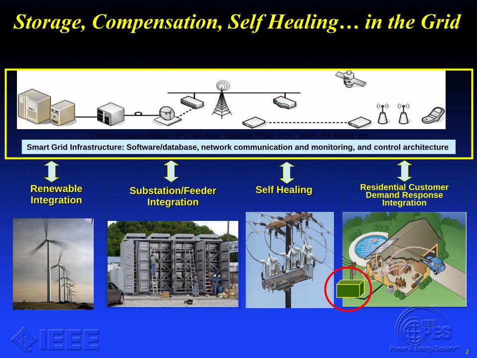
Storage, Compensation, Self Healing… in the Grid
Communication Media: BPL, Wi-Max, Satellite, Fiber, DSL, Wi-Fi, RF Mesh, etc.
Smart Grid Infrastructure: Software/database, network communication and monitoring, and control architecture
Substation/Feeder Integration
Residential Customer Demand Response
Integration
Renewable Integration
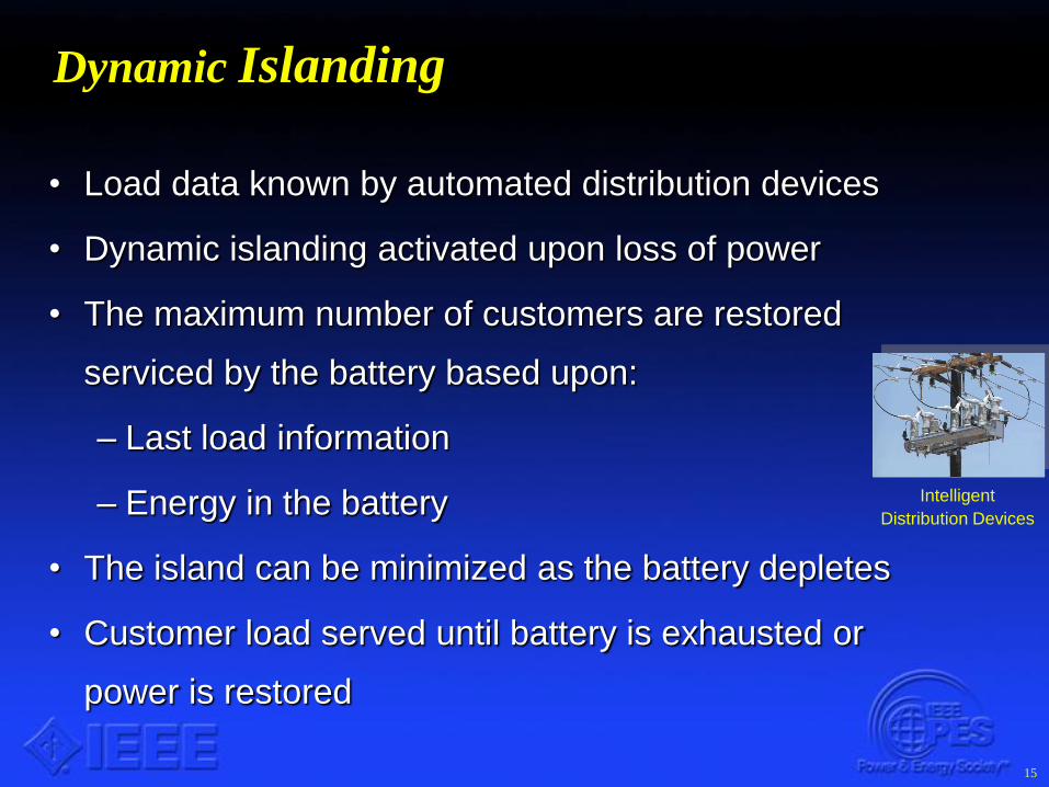
Self Healing
3
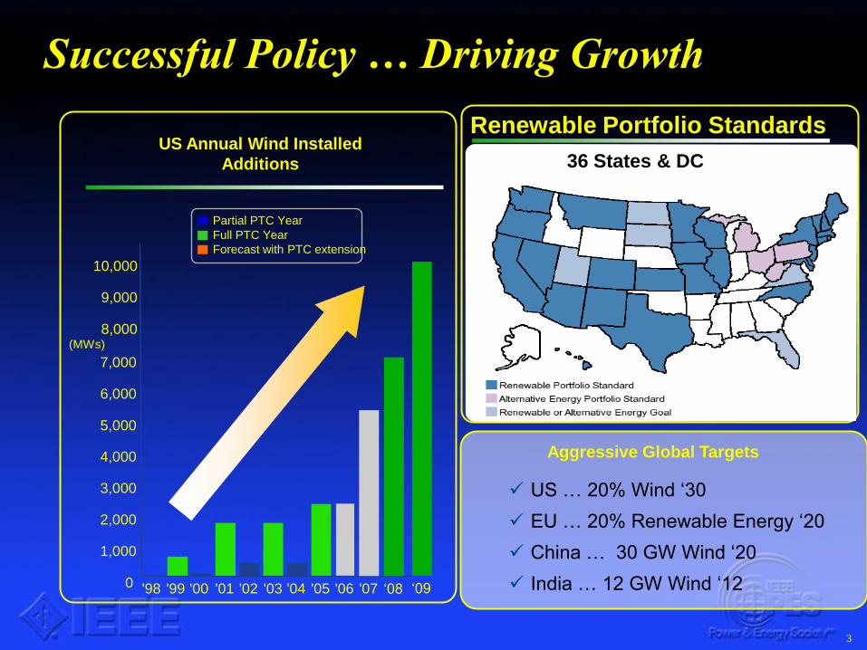
US … 20% Wind ‘30
EU … 20% Renewable Energy ‘20
China … 30 GW Wind ‘20
India … 12 GW Wind ‘12
Successful Policy … Driving Growth
1,000
2,000
3,000
4,000
'98 '99 '00 '01 '02 '03 '04 '05 '06
5,000
6,000
7,000
0
US Annual Wind Installed
Additions
Partial PTC Year
Full PTC Year
Forecast with PTC extension
(MWs)
'07 ‘08
Renewable Portfolio Standards
36 States & DC
‘09
8,000
9,000
10,000
Aggressive Global Targets
4
Reactive Power Requirements
• Capability of synchronous generators forms
basis for wind interconnection requirements
• FERC Order 661A is a USA grid code for
maintaining power flow limits, voltage limits,
and voltage control:
– Low voltage ride-through (LVRT)• Generator stays on line during a 3 phase
fault with normal fault clearing (~4 to 9 cycles) and subsequent post fault voltage recovery to prefault voltage unless clearing the fault disconnects the generator
– Power factor +/- .95 with dynamic voltage support
5
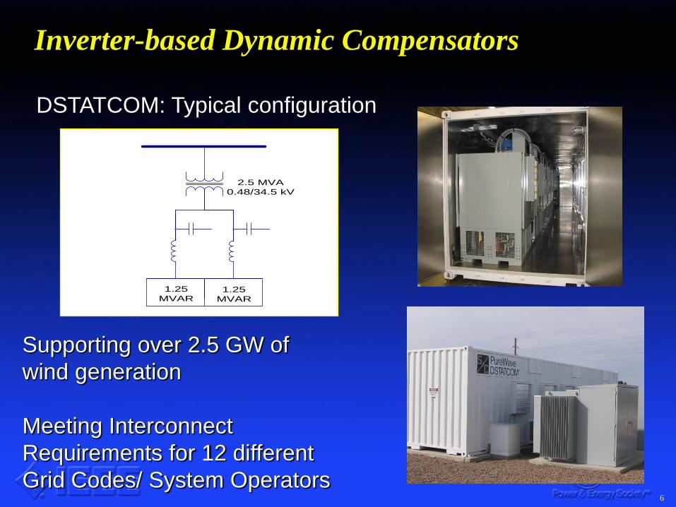
Reactive Power Compensation
• Collector substation-based systems
– Mechanically-switched capacitors and reactor banks
– Static Var Compensators
– Hybrid compensators
• Inverter-based dynamic component
– 1.25 MVAR modules
– 264% of continuous rating for 2 to 4 seconds
• LVRT support
• Dynamic range requirement
– For transient / dynamic events
– Use with mechanically switched capacitors and reactors