Increasing performance of electronic components is resulting in higher heat flux dissipation.Two-phase Passive devices are proven solutions for modern microelectronics thermalmanagement. In this context, Pulsating Heat Pipe (PHP) cooling is the new and emergingtechnique in the field of thermal management of electronics. In the present work, transient andsteady state experiments are conducted on a two turn closed loop PHP. Copper is used as thecapillary tube material in the evaporator and condenser sections with inner diameter of 2 mmand outer diameter of 3 mm. The total length of the closed loop pulsating heat pipe is 1080 mm.The evaporator and condenser sections are 360 mm and 280 mm respectively. The experimentsare conducted on vertical orientations for different heat loads varying from 10 W to 100 W insteps of 10 W. The PHP is tested on Ethanol, Methanol, Acetone and Water as working fluids fordifferent fill ratios from 0% to 100% in steps of 20%. The performance parameters such astemperature difference between evaporator and condenser, thermal resistance and the overallheat transfer coefficient are evaluated. The experimental results demonstrate the heat transfercharacteristics, lower thermal resistance and higher heat transfer coefficient of PHP are foundto be better at a fill ratio of 60% for various heat input.
Keywords: Pulsating heat pipe, Fill ratio, Orientation, Working fluids
INTRODUCTIONThermal management is the challenge of theday in electronic product development. Theamount of excess heat generated by theelectronic devices and circuitry has increasedenormously. All electronic components from
ISSN 2278 – 0149 www.ijmerr.comVol. 2, No. 3, July 2013
1 Government College of Engineering, Near Katora Naka, Amravati 444601, India.
microprocessors to high-end powerconverters generate heat and rejection of thisheat is necessary for their optimum andreliable operation. As electronic design allowshigher output in smaller packages, effectiveheat load dissipation becomes a critical
Research Paper
114
Int. J. Mech. Eng. & Rob. Res. 2013 Dharmapal A Baitule and Pramod R Pachghare, 2013
design factor. Many of the present dayselectronic devices require cooling beyond thecapability of conventional metallic heat sinks.One solution to remove excess heat is byutilization of heat pipes which are employedto remove the excess heat by directly attachingthem to the heat source. The Oscillating orPulsating Heat Pipe (PHP) is anotherpromising heat transfer device for applicationslike electronic cabinet cooling. These simplelooking devices have intriguing thermo-hydrodynamic operational characteristics. APHP is partially filled with working fluid whichdistributes itself naturally in the form of liquidslugs and vapour plugs inside the capillarytubes. One end of this tube bundle (evaporatorsection) receives heat, transferring it to theother end (condenser section) by a pulsatingaction of the liquid-vapour system. A PHP isessentially a non equilibrium heat transferdevice driven by complex combination ofvarious types of two-phase flow instabilities.The performance success of a PHP primarilydepends on the continuous maintenance orsustenance of these non equilibriumconditions. The liquid slugs and vapour plugsare transported because of the pressurepulsations caused inside the system. Theconstruction of the device inherently ensuresthat no external mechanical power source isneeded for the fluid transport. The drivingpressure pulsations are fully thermally driven.
Single and multiple loop PHP studies arewidely reported in the literature. These studieshighlight the influence of various designparameters of PHP on its performance.
Working of Closed Loop PulsatingHeat PipeThe tube is first evacuated and then filledpartially with a working fluid. If the inner
diameter of the capillary tube is small enoughsuch that the working fluid will distribute itselfalong the tube length forming liquid slugs andvapor bubbles due to the effect of surfacetension. Under operating condition, the tube-bundle of a PHP receives heat at one endand is cooled at the other. Due to boiling andevaporation, bubble generation and growthcontinually occurs in the evaporator.Simultaneously, bubbles collapse and shrinkdue to condensation in the condenser. Theresulting effect of the action of bubbles actsas pumping elements, providing themomentum or uneven hydrostatic pressureneeded to move slugs or bubbles tolocations where evaporation, boiling, andcondensation can occur. Therefore, thetransport of liquid slug and vapor bubble iscaused by the thermally induced pressurepulsations inside the device and no externalmechanical power is required. The heattransfer, essentially as a combination ofsensible and latent heat portions, is causedby the transport.
Factor Affecting Closed LoopPulsating Heat Pipe
It can be seen that six major thermo-mechanical parameters have emerged as theprimary design parameters affecting the PHPsystem dynamics. These include:
• Internal diameter of the PHP tube,
• Input heat flux to the device,
• Volumetric filling ratio of the workingfluid,
• Total number of turns,
• Device orientation with respect to gravity,
• Working fluid thermo-physical properties.
115
Int. J. Mech. Eng. & Rob. Res. 2013 Dharmapal A Baitule and Pramod R Pachghare, 2013
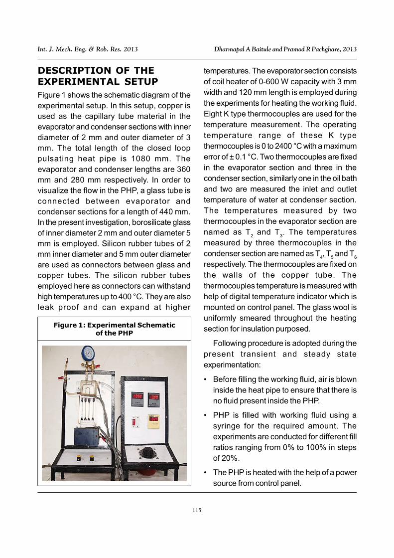
DESCRIPTION OF THEEXPERIMENTAL SETUPFigure 1 shows the schematic diagram of theexperimental setup. In this setup, copper isused as the capillary tube material in theevaporator and condenser sections with innerdiameter of 2 mm and outer diameter of 3mm. The total length of the closed looppulsating heat pipe is 1080 mm. Theevaporator and condenser lengths are 360mm and 280 mm respectively. In order tovisualize the flow in the PHP, a glass tube isconnected between evaporator andcondenser sections for a length of 440 mm.In the present investigation, borosilicate glassof inner diameter 2 mm and outer diameter 5mm is employed. Silicon rubber tubes of 2mm inner diameter and 5 mm outer diameterare used as connectors between glass andcopper tubes. The silicon rubber tubesemployed here as connectors can withstandhigh temperatures up to 400 °C. They are alsoleak proof and can expand at higher
temperatures. The evaporator section consistsof coil heater of 0-600 W capacity with 3 mmwidth and 120 mm length is employed duringthe experiments for heating the working fluid.Eight K type thermocouples are used for thetemperature measurement. The operatingtemperature range of these K typethermocouples is 0 to 2400 °C with a maximumerror of ± 0.1 °C. Two thermocouples are fixedin the evaporator section and three in thecondenser section, similarly one in the oil bathand two are measured the inlet and outlettemperature of water at condenser section.The temperatures measured by twothermocouples in the evaporator section arenamed as T
2 and T
3. The temperatures
measured by three thermocouples in thecondenser section are named as T
4, T
5 and T
6
respectively. The thermocouples are fixed onthe walls of the copper tube. Thethermocouples temperature is measured withhelp of digital temperature indicator which ismounted on control panel. The glass wool isuniformly smeared throughout the heatingsection for insulation purposed.
Following procedure is adopted during thepresent transient and steady stateexperimentation:
• Before filling the working fluid, air is blowninside the heat pipe to ensure that there isno fluid present inside the PHP.
• PHP is filled with working fluid using asyringe for the required amount. Theexperiments are conducted for different fillratios ranging from 0% to 100% in stepsof 20%.
• The PHP is heated with the help of a powersource from control panel.
Figure 1: Experimental Schematicof the PHP
116
Int. J. Mech. Eng. & Rob. Res. 2013 Dharmapal A Baitule and Pramod R Pachghare, 2013
• The cooling water is allowed to flow throughthe PHP to the condenser section of PHPfrom the constant water bath at a flow rateof 30 ml/min.
• The required wattage is set using thedimmer and the heat load is varied from 10W to 100 W insteps of 10 W.
• Experiments are conducted in verticalorientation of PHP with different Ethanolworking.
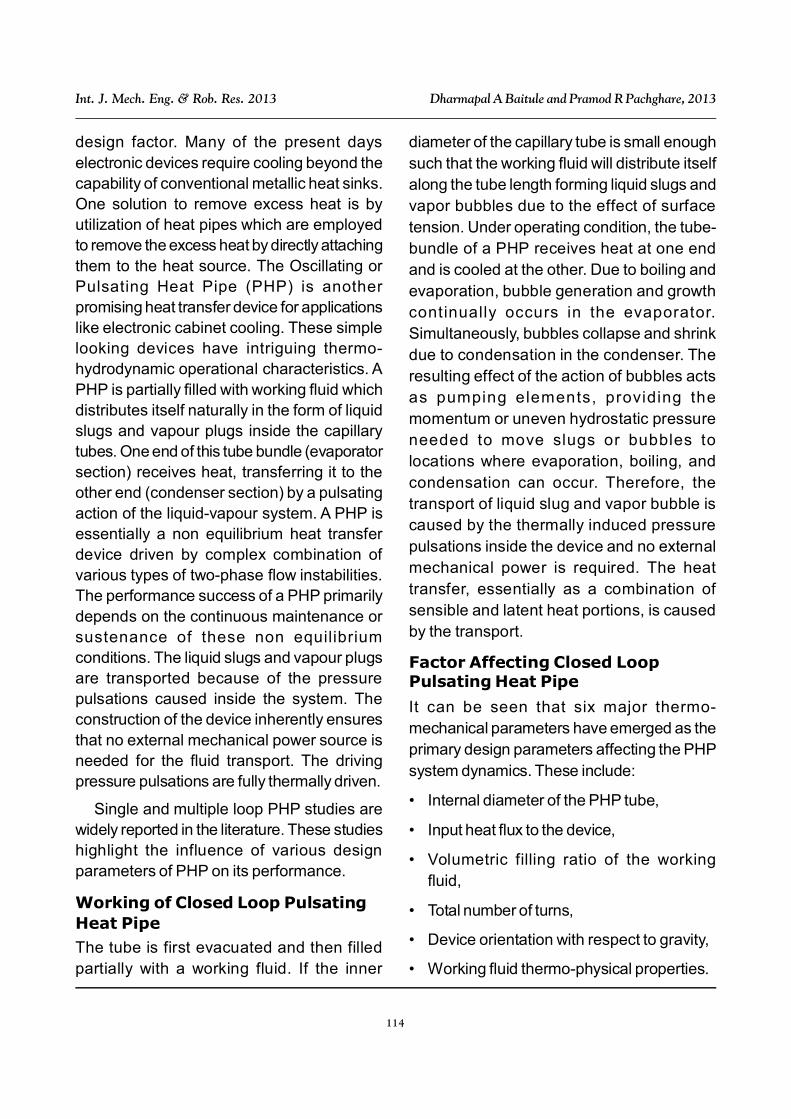
RESULTS AND DISCUSSIONTransient and steady state experiments areconducted with Ethanol, Methanol, Acetoneand Water as working fluids. The experimentsare carried out at different heat loads and fillratio, the evaporator and condenser walltemperature readings are recorded. Figures2 to 5 show the variation of overall thermalresistance R
th = (Te – Tc)/Q of the PHP with
increasing heat input power Q for differentfilling ratios for various working fluid. From theliterature review I am consider 20% of heat lost
Figure 2: Typical Variation of ThermalResistance with Heat Input Power
at Different Fill Ratio for Ethanol Fill in PHP
Figure 3: Typical Variation of ThermalResistance with Heat Input Power
at Different Fill Ratios for Methanol FilledPHP
Figure 4: Typical Variation of ThermalResistance with Heat Input Power
at Different Fill Ratios for Acetone FilledPHP
in the surrounding, therefore all the calculationis carried out by 20% of heat lost of total heatload. This heat is lost trough the condensersection, evaporator section and adiabaticsection.
117
Int. J. Mech. Eng. & Rob. Res. 2013 Dharmapal A Baitule and Pramod R Pachghare, 2013
Operational Extremities
For 0% filling ratio, the PHP runs withoutany fluid inside it and this serves as thereference Measurement. Obviously the modeof heat transfer is by pure conduction in PHP.The other extreme is when the PHP is fully filledwith the working fluid (FR = 100%). In this modethe heat transfer is due to the single-phasebuoyancy induced liquid circulation in the PHP.In this case the local heat transfer coefficientin the tubes is only a function of fluid Grashofand Prandtl numbers. There is a smoothdecrease of the thermal resistance withincreasing heat power input. Similarly low inputheat fluxes were not capable of generatingenough perturbations and the resulting bubblepumping action was extremely restricted. Overall, this scenario results in poor performance(i.e., very high thermal resistance).
As the heat input was increased, itimproved the heat transfer coefficient tomarked degree. Still higher input heat fluxes
resulted in bulk flow taking a fixed directionthat did not reverse with time. This circulationwas manifested as adjacent tube becomingalternately hot and cold. Interestingly, in such acase lowest thermal resistance was observed.
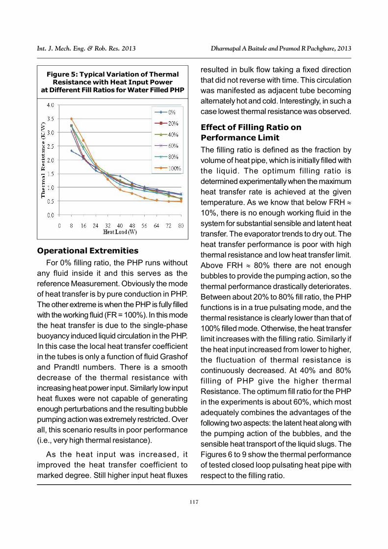
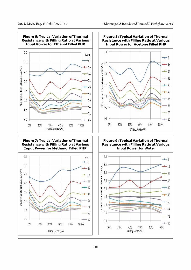
Effect of Filling Ratio onPerformance Limit
The filling ratio is defined as the fraction byvolume of heat pipe, which is initially filled withthe liquid. The optimum filling ratio isdetermined experimentally when the maximumheat transfer rate is achieved at the giventemperature. As we know that below FRH 10%, there is no enough working fluid in thesystem for substantial sensible and latent heattransfer. The evaporator trends to dry out. Theheat transfer performance is poor with highthermal resistance and low heat transfer limit.Above FRH 80% there are not enoughbubbles to provide the pumping action, so thethermal performance drastically deteriorates.Between about 20% to 80% fill ratio, the PHPfunctions is in a true pulsating mode, and thethermal resistance is clearly lower than that of100% filled mode. Otherwise, the heat transferlimit increases with the filling ratio. Similarly ifthe heat input increased from lower to higher,the fluctuation of thermal resistance iscontinuously decreased. At 40% and 80%filling of PHP give the higher thermalResistance. The optimum fill ratio for the PHPin the experiments is about 60%, which mostadequately combines the advantages of thefollowing two aspects: the latent heat along withthe pumping action of the bubbles, and thesensible heat transport of the liquid slugs. TheFigures 6 to 9 show the thermal performanceof tested closed loop pulsating heat pipe withrespect to the filling ratio.
Figure 5: Typical Variation of ThermalResistance with Heat Input Power
at Different Fill Ratios for Water Filled PHP
118
Int. J. Mech. Eng. & Rob. Res. 2013 Dharmapal A Baitule and Pramod R Pachghare, 2013
Figure 6: Typical Variation of ThermalResistance with Filling Ratio at Various
Input Power for Ethanol Filled PHP
Figure 7: Typical Variation of ThermalResistance with Filling Ratio at Various
Input Power for Methanol Filled PHP
Figure 8: Typical Variation of ThermalResistance with Filling Ratio at Various
Input Power for Acetone Filled PHP
Figure 9: Typical Variation of ThermalResistance with Filling Ratio at Various
Input Power for Water
119
Int. J. Mech. Eng. & Rob. Res. 2013 Dharmapal A Baitule and Pramod R Pachghare, 2013
Effect of Fill Ratio on Temperature
The Figures 10 to 13 shows the temperaturedifference between evaporation andcondenser section for different filling ratio at
Figure 10: The Temperature Differencein Evaporator and Condenser Section
at Different Heat Input for Ethanolas Working Fluid
Figure 11: The Temperature Differencein Evaporator and Condenser Sectionat Different Heat Input for Acetone
as Working Fluid
Figure 12: The Temperature Differencein Evaporator and Condenser Sectionat Different Heat Input for Acetone
as Working Fluid
Figure 13: The Temperature Differencein Evaporator and Condenser Sectionat Different Heat Input for Acetone
as Working Fluid
120
Int. J. Mech. Eng. & Rob. Res. 2013 Dharmapal A Baitule and Pramod R Pachghare, 2013
various heat input. The vapour bubblesformation is regulating the pumping action inthe PHP. If the bubbles higher in PHP, the heattransfer rate also higher from evaporatorsection to condenser section. The figure showthat at 60% filling ratio of PHP give the lowertemperature difference as compare to otherfilling ratio. Therefore we can say that at 60%filling of PHP give the higher heat transfer rateand lower thermal resistance. When we usedthe Acetone as working fluid in PHP, the PHPgive the better result as compare to otherworking fluid up to 48 watt.
CONCLUSIONThe results from model are summarized asfollows:
• The thermal resistance of closed looppulsating heat pipe decrease with theincrease of heat input. At the lower heat input(Q 60 W) the thermal resistance isdecreased slowly and at higher heat input(Q 60 W) the difference is smaller.
• The thermal resistances have the results ofR
acetone < R
methanol < R
ethanol < R
water. This
condition is occurs up to 48 W and abovethe 48 W the thermal Resistance of Acetoneis increased slightly.
• The filling ratio is a critical parameter, whichneeds to be optimized to achieve maximumthermal performance and minimum thermalresistance for a given operating condition.From this experimental setup we areconclude that at 60% filling of PHP give theoptimum result.
REFERENCES1. Honghai Yang S and Khandekar M Groll
(2008), “Operational Limit of Closed Loop
Pulsating Heat Pipes”, Applied ThermalEngineering, Vol. 28, pp. 49-59.
2. Jian Qu, Huiying Wu, Ping Cheng andXiong Wang (2009), “Non-LinearAnalyses of Temperature Oscillations ina Closed-Loop Pulsating Heat Pipe”,International Journal of Heat and MassTransfer, Vol. 52, pp. 3481-3489.
3. Khandekar S (2006), “Insights into thePerformance Modes of Closed LoopPulsating Heat Pipe and Pulsating HeatPipe and Some Design Hints”, Heat andMass Conference, January.
4. Mauro Mameli, Sameer Khandekar andMarco Marengo (2011), “Flow Patternsand Corresponding Local Heat TransferCoefficients in a Pulsating Heat Pipe”,Proceedings of the 29th National HeatTransfer Conference of Italy, June 20-22,Politecnico di Torino, Torino, Italy.
5. Rudra Naik, Venugopal Varadarajan,Pundarika G and Rama Narasimha K(2005), “Experimental Investigation andPerformance Evaluation of a ClosedLoop Pulsating Heat Pipe”.
6. Sameer Khandekar and Manfred Groll(2004), “An Insight into Thermo-Hydrodynamic Couplingin Closed LoopPulsating Heat Pipes”, InternationalJournal of Thermal Sciences, Vol. 43,pp. 13-20.
7. Sameer Khandekar, Nicolas Dollingerand Manfred Groll (2003), “UnderstandingOperational Regimes of Closed LoopPulsating Heat Pipes: An ExperimentalStudy”, Applied Thermal Engineering,Vol. 23, pp. 707-719.
121
Int. J. Mech. Eng. & Rob. Res. 2013 Dharmapal A Baitule and Pramod R Pachghare, 2013
8. Shi Liu Jingtao, Li Xiangyuan and DongHuanzhuo Chen (2007), “ExperimentalStudy of Flow Patterns and ImprovedConfigurations for Pulsating Heat Pipes”,Journal of Thermal Science, Vol. 16,No. 1, pp. 56-62.
9. Yu-Hsing Lin, Shung-Wen Kang and Hui-Lun Chen (2008), “Effect of Silver Nano-Fluid on Pulsating Heat Pipe ThermalPerformance”, Applied ThermalEngineering, Vol. 28, pp. 1312-1317.