Shewale, V. C., et al.: Experimental and Numerical Analysis of Convective Heat Losses ... THERMAL SCIENCE: Year 2017, Vol. 21, No. 3, pp. 1321-1334 1321 EXPERIMENTAL AND NUMERICAL ANALYSIS OF CONVECTIVE HEAT LOSSES FROM SPHERICAL CAVITY RECEIVER OF SOLAR CONCENTRATOR by Vinod C. SHEWALE a * , Prashant R. DONGARWAR b , and Rupesh R. GAWANDE a a Department of Mechanical Engineering, NDMVPS KBT College of Engineering, Nashik, India b Department of Mechanical Engineering, College of Military Engineering, Pune, India c Department of Mechanical Engineering, B. D. College of Engineering, Nagpur University, Wardha, India Original scientific paper https://doi.org/10.2298/TSCI150601165S Spherical cavity receiver of solar concentrator is made up of Cu tubing material having cavity diameter 385 mm to analyze the different heat losses such as conduc- tion, convection and radiation. As the convection loss plays major role in heat loss analysis of cavity receiver, the experimental analysis is carried out to study convec- tive heat loss for the temperature range of 55-75 °C at 0°, 15°, 30°, 45°, 60°, and 90° inclination angle of downward facing cavity receiver. The numerical analysis is carried out to study convective heat loss for the low temperature range (55-75 °C) as well as high temperature range (150-300 °C) for no wind condition only. The ex- perimental set-up mainly consists of spherical cavity receiver which is insulated with glass wool insulation to reduce the heat losses from outside surface. The numerical analysis is carried out by using CFD software and the results are compared with the experimental results and found good agreement. The result shows that the con- vective loss increases with decrease in cavity inclination angle and decreases with decrease in mean cavity receiver temperature. The maximum losses are obtained at 0° inclination angle and the minimum losses are obtained at 90° inclination angle of cavity due to increase in stagnation zone in to the cavity from 0° to 90° inclination. The Nusselt number correlation is developed for the low temperature range 55-75 °C based on the experimental data. The analysis is also carried out to study the effect of wind speed and wind direction on convective heat losses. The convective heat losses are studied for two wind speeds (3 m/s and 5 m/s) and four wind directions [α is 0° (Side-on wind), 30°, 60°, and 90° (head-on wind)]. It is found that the convective heat losses for both wind speed are higher than the losses obtained by no wind test. The highest heat losses are found for wind direction α is 60° with respect to receiver stand and lowest heat losses are found for wind direction α is 0° (side-on wind). The heat losses obtained for wind direction, α, is 30° condition are higher than the heat losses obtained for wind direction α is 0° (side-on wind) condition, while the heat losses obtained by wind direction α is 90° (head-on wind) condition are less than the heat losses obtained for wind direction, α, is 60° condition. Key words: spherical cavity receiver, heat losses, wind effect, experimental analysis Introduction Cavity receiver is a key component of any solar system and the efficiency of solar system mainly depends on the performance of cavity receiver. Therefore, the efficiency of cav- * Corresponding author, e-mail: vinods31576@rediffmail.com
Transcript
Shewale, V. C., et al.: Experimental and Numerical Analysis of Convective Heat Losses ... THERMAL SCIENCE: Year 2017, Vol. 21, No. 3, pp. 1321-1334 1321
EXPERIMENTAL AND NUMERICAL ANALYSIS OF CONVECTIVE HEAT LOSSES FROM SPHERICAL CAVITY RECEIVER
OF SOLAR CONCENTRATOR
by
Vinod C. SHEWALE a *, Prashant R. DONGARWAR b, and Rupesh R. GAWANDE aa Department of Mechanical Engineering, NDMVPS KBT College of Engineering, Nashik, India
b Department of Mechanical Engineering, College of Military Engineering, Pune, India c Department of Mechanical Engineering, B. D. College of Engineering, Nagpur University,
Wardha, India
Original scientific paper https://doi.org/10.2298/TSCI150601165S
Spherical cavity receiver of solar concentrator is made up of Cu tubing material having cavity diameter 385 mm to analyze the different heat losses such as conduc-tion, convection and radiation. As the convection loss plays major role in heat loss analysis of cavity receiver, the experimental analysis is carried out to study convec-tive heat loss for the temperature range of 55-75 °C at 0°, 15°, 30°, 45°, 60°, and 90° inclination angle of downward facing cavity receiver. The numerical analysis is carried out to study convective heat loss for the low temperature range (55-75 °C) as well as high temperature range (150-300 °C) for no wind condition only. The ex-perimental set-up mainly consists of spherical cavity receiver which is insulated with glass wool insulation to reduce the heat losses from outside surface. The numerical analysis is carried out by using CFD software and the results are compared with the experimental results and found good agreement. The result shows that the con-vective loss increases with decrease in cavity inclination angle and decreases with decrease in mean cavity receiver temperature. The maximum losses are obtained at 0° inclination angle and the minimum losses are obtained at 90° inclination angle of cavity due to increase in stagnation zone in to the cavity from 0° to 90° inclination. The Nusselt number correlation is developed for the low temperature range 55-75 °C based on the experimental data. The analysis is also carried out to study the effect of wind speed and wind direction on convective heat losses. The convective heat losses are studied for two wind speeds (3 m/s and 5 m/s) and four wind directions [α is 0° (Side-on wind), 30°, 60°, and 90° (head-on wind)]. It is found that the convective heat losses for both wind speed are higher than the losses obtained by no wind test. The highest heat losses are found for wind direction α is 60° with respect to receiver stand and lowest heat losses are found for wind direction α is 0° (side-on wind). The heat losses obtained for wind direction, α, is 30° condition are higher than the heat losses obtained for wind direction α is 0° (side-on wind) condition, while the heat losses obtained by wind direction α is 90° (head-on wind) condition are less than the heat losses obtained for wind direction, α, is 60° condition. Key words: spherical cavity receiver, heat losses, wind effect, experimental analysis
Introduction
Cavity receiver is a key component of any solar system and the efficiency of solar system mainly depends on the performance of cavity receiver. Therefore, the efficiency of cav-
Shewale, V. C., et al.: Experimental and Numerical Analysis of Convective Heat Losses ... 1322 THERMAL SCIENCE: Year 2017, Vol. 21, No. 3, pp. 1321-1334
ity receiver can be improved by minimizing the losses of cavity receiver of solar concentrator. Many researchers have done the analysis of heat losses for different geometry cavity receiver to minimize it. Clausing [1] analyzed a cavity solar central receiver for convective losses by presenting an analytical model. The model shows the internal thermal resistance i. e. the impor-tance of ability to heat air in to the cavity and influence of wind on convective losses. Harris and Lenz [2] analyzed six types of cavity geometries such as cylindrical, heteroconical, spherical, elliptical, and conical which estimates the system efficiency and cavity power profile. Taumoe-folau et al. [3] studied the electrically heated cylindrical cavity for natural convection losses with different cavity orientation and operating temperature form 450 °C to 650 °C. They also studied the effect of ratio of aperture diameter to cavity diameter for natural convection losses and numerically analyzed the convective losses with CFD software. Leibfried and Ortjohann [4] have studied the convective heat loss from upward and downward facing cavity receiver of solar concentrator for spherical and hemispherical shaped cavity. They constructed an ex-perimental set-up for both cavities and analyzed for convective losses for different inclination angles (–90° to +90°). They also studied the effect of different aperture diameter ranged from 60 mm to 195 mm with operating temperature between 573 K and 873 K on convective heat loss. Stine and McDonald [5] studied the effect of tilt angle of cavity, geometry, and tempera-ture of cavity experimentally by using full size cavity receiver for convection losses. They also developed the correlation by considering the cavity temperature, tilt angle, and different geom-etry of cavity receiver. Jilte et al. [6] studied different cavity shapes such as cylindrical, conical, dome cylindrical, hetroconical, reverse conical, and spherical numerically for combined natural convection and radiation heat losses. Koenig and Marvin [7] studied a model for heat losses based on high cavity surface temperature between 550-900 °C and proposed an empirical cor-relation.
Prakash et al. [8] carried out experimental and numerical study to identify stagnation zone and convective zone in cylindrical cavity receiver of length 0.5 m and diameter 0.3 m. They conducted experiments for low and medium fluid inlet temperatures between 50-150 °C for different inclination angle of cavity receiver. Clausing [9] studied the convective heat losses by using analytical method for upward facing large cubical cavity which is used in solar tower and compared with experimental results. Quere et al. [10] carried experimental and numerical study for opening ratio of 1 and at inclination from –90° to +90°. They found the larger vari-ation of Nusselt number i. e. 5% from the experimental and numerical simulation for cavities. Sendhil Kumar and Reddy [11] used 2-D model for the estimation of convection loss of modi-fied cavity receiver by assuming the uniform and peak solar flux distribution in to the receiver. Prakash et al. [12] carried out experimental investigation to study the total and convective heat losses for cylindrical cavity receiver having aperture diameter of cavity is greater than the cav-ity diameter. They also studied the effect of wind on total and convective losses for 1 m/s and 3 m/s wind velocity. Ma [13] has investigated the convective heat losses under wind conditions for cylindrical cavity receiver. He carried out the experiment for the wind speed greater than the 3 m/s velocity of air and found the similar results to that of no wind condition. Paitoonsurikarn and Lovegrove [14] investigate the natural convection heat loss in cavity type solar receiver nu-merically and they found that the convective heat losses increased with decrease in inclination angle of cavity receiver. Prakash et al. [15] analyzed convective heat loss from three different cavity receiver such as cubical, spherical, and hemispherical. They also performed numerical analysis by using CFD software and studied the effect of opening ratio on convection loss at different inclination angle of cavity receiver.
Shewale, V. C., et al.: Experimental and Numerical Analysis of Convective Heat Losses ... THERMAL SCIENCE: Year 2017, Vol. 21, No. 3, pp. 1321-1334 1323
Hess and Henze [16] investigate the natural convection losses experimentally for hor-izontal rectangular open cavities at different inclination angles. They found that natural con-vection loss can be reduced up to 10% by using flow restriction at the aperture plane. Chan and Tien [17] studied estimation of natural convection in shallow open cavities. This numerically 2-D study carried out for minimizing the convection losses at various inclination of cavity. Har-ris and Lenz [2] analyzed five geometries of cavity receivers cylindrical, spherical, elliptical, conical and heteroconical for thermal performance. They obtained considerable variations on power profile of cavity geometry and rim angle deviation of concentrator. Reddy et al. [18] an-alyzed the performance of receiver for solar parabolic trough concentrator at different heat flux conditions and for the different fin aspect ratio. Paitoonsurikarn and Lovegrove [19] studied three different receiver geometries for numerical investigation of natural convection loss. They studied combined free-forced convection which includes the effect of wind speed and direction on convection loss and developed a new correlation based on the numerical results of three cavity receivers. McDonald [20] studied the heat losses from open cavity receiver at different orientation of cavity and different opening ratio of cavity receiver. He found the maximum loss-es at high opening ratio and minimum losses at low opening ratio. Sendhil Kumar and Reddy [21] and Reddy and Sendhil Kumar [22] studied numerically combined natural convection and surface radiation in 2-D modified cavity receivers by using CFD software and developed an ac-curate Nusselt number correlation to estimate accurate natural convection heat loss. They also investigate numerically natural convective heat loss in modified cavity receiver for fuzzy focal solar concentrator. Wu et al. [23] conducted an experimental study for different heat losses to fully open cylindrical cavity considering different boundary conditions.
Many researchers worked on analysis of different cavity receivers such as cylindrical, conical, spherical, cubical, elliptical, etc. Few researchers have studied the effect of side on wind condition and head on wind condition for heat losses to cavity receiver of solar concentra-tor, but no attempt has been made to study the effect of wind directions in between side on wind and head on wind condition on heat losses. In this paper four wind directions with respect to receiver stand are considered to study the heat losses for spherical cavity reciever. The research and analysis of spherical cavity receiver is limited so there is need to study different heat loss-es from cavity receiver by considering the effect of wind speed, wind direction, and different parameters of cavity receiver. In this paper, Cu tube material spherical cavity receiver having cavity diameter 0.385 m and opening diameter 0.154 m is used to study the effect of wind speed and wind direction on heat losses which is not yet considered in any previous study.
Experimental analysis and methodology
Details of cavity receiver
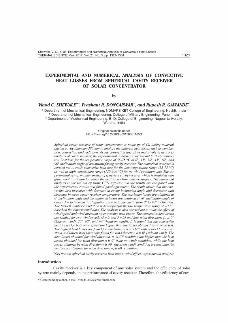
The spherical cavity receiver used in the present analysis which is made by Cu tube material is shown in fig. 1. The internal diameter of cavity receiver is 0.385 m and opening diameter is 0.154 m and has 43 numbers of turns of Cu coil. The diameter of Cu tube is 0.009 m. The spacing between the two coils is from 0.001 m to 0.003 m. A layer of glass wool insulation 100 mm thick are provided on the surface of cavity receiver which cov-ered with aluminum cladding on outer surface to reduce the heat losses. The back side of cavity receiver is closed by small circular Cu plate.
Figure 1. Front view of spherical cavity receiver
Shewale, V. C., et al.: Experimental and Numerical Analysis of Convective Heat Losses ... 1324 THERMAL SCIENCE: Year 2017, Vol. 21, No. 3, pp. 1321-1334
Experimental set-up and procedure
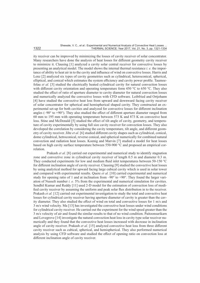
The schematic diagram of experimental set-up is shown in fig. 2, which is used for low temperature test from 55-75 °C. The set-up mainly consists of a downward facing spherical cavity receiver supported by stand and angle adjustment mechanism is provided to incline the cavity at inclination angles 0°, 15°, 30°, 45°, 60°, and 90° with respect to horizontal.
Figure 2. Schematic diagram of the experimental set-up
Spherical cavityreceiver
Hot water inlet
Stand forreceiver Rotameter
ValveValve
ValvePump
Heaters
Air ventOverflow
Waterstoragetank
Water inlet
Wateroutlet
Drain
Bypass line
Stand forrotameter
The hot water is used as a working fluid into the receiver tubes and a tank of capacity 140 liter having two numbers of heater (2 kW each) used for storage of hot water. A pump of capacity 0.25 hp is used for circulating the hot water through the cavity receiver tubes and the mass flow rate of water, which enters in to the cavity is measured with the help of rotameter. The tube temperature of cavity receiver and air temperature into the cavity receiver are measured with 15 K-type thermocouples at different locations in to the cavity receiver. The fluid inlet and outlet temperatures are measured with two K-type thermocouples. The ambient temperature was measured from the location, where there is no effect of receiver temperature. Data acqui-sition system is used to record the data of temperature measurement. The hot water circulated through the receiver at constant inlet temperature and constant mass flow rate during the period of experimental run and the water from the outlet of cavity receiver again returned to the storage tank. The wind tests are carried out by using the blower assembly in which a square tunnel of sheet metal is attached to the blower door. Inside the tunnel there is metal mesh section which gives the straight and uniform air-flow in to the cavity. The uniform air-flow is confirmed by checking the speed of wind at different location of aperture plane with the help of anemometer. All K-type thermocouples and rotameter used in the experimental set-up for measurements are calibrated from laboratory. The error considered in the thermocouple reading is ±0.8 % for the temperature range of 55-75 °C, while the error considered in rotameter reading is ±3% for the measurement of mass flow rate 50 kg/hr. Therefore, the overall confidence interval (CI) for total heat loss is calculated as 91.88%.
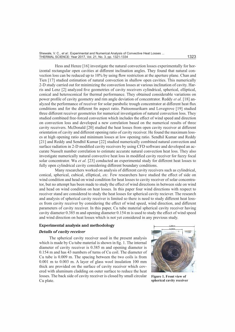
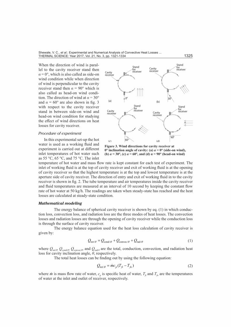
Here four types of wind directions are studied which are shown in fig. 3. The angle of wind direction is denoted by α with respect to cavity receiver stand as shown in fig. 3.
Shewale, V. C., et al.: Experimental and Numerical Analysis of Convective Heat Losses ... THERMAL SCIENCE: Year 2017, Vol. 21, No. 3, pp. 1321-1334 1325
When the direction of wind is paral-lel to the cavity receiver stand then α = 0°, which is also called as side-on wind condition while when direction of wind is perpendicular to the cavity receiver stand then α = 90° which is also called as head-on wind condi-tion. The direction of wind at α = 30° and α = 60° are also shown in fig. 3 with respect to the cavity receiver stand in between side-on wind and head-on wind condition for studying the effect of wind directions on heat losses for cavity receiver.
Procedure of experiment
In this experimental set-up the hot water is used as a working fluid and experiment is carried out at different inlet temperatures of hot water such as 55 °C, 65 °C, and 75 °C. The inlet temperature of hot water and mass flow rate is kept constant for each test of experiment. The inlet of working fluid is at the top of cavity receiver and exit of working fluid is at the opening of cavity receiver so that the highest temperature is at the top and lowest temperature is at the aperture side of cavity receiver. The direction of entry and exit of working fluid in to the cavity receiver is shown in fig. 2. The tube temperature and air temperatures inside the cavity receiver and fluid temperatures are measured at an interval of 10 second by keeping the constant flow rate of hot water at 50 kg/h. The readings are taken when steady-state has reached and the heat losses are calculated at steady-state condition.
Mathematical modeling
The energy balance of spherical cavity receiver is shown by eq. (1) in which conduc-tion loss, convection loss, and radiation loss are the three modes of heat losses. The convection losses and radiation losses are through the opening of cavity receiver while the conduction loss is through the surface of cavity receiver.
The energy balance equation used for the heat loss calculation of cavity receiver is given by:
tot / cond/ convec/ rad/Q Q Q Qθ θ θ θ= + + (1)
where Qtot/θ, Qcond/θ, Qconvec/θ, and Qrad/θ are the total, conduction, convection, and radiation heat loss for cavity inclination angle, θ, respectively.
The total heat losses can be finding out by using the following equation:
tot / ( )p fi foQ mc T Tθ = − (2)
where m is mass flow rate of water, cp is specific heat of water, Tfi and Tfo are the temperatures of water at the inlet and outlet of receiver, respectively.
Figure 3. Wind directions for cavity receiver at 0° inclination angle of cavity: (a) α = 0° (side-on wind), (b) α = 30°, (c) α = 60°, and (d) α = 90° (head-on wind)
90°
30°
60°
Standforreceiver
Standforreceiver
Cavityreceiver
Cavityreceiver
Standforreceiver
StandforreceiverCavity
receiver Cavityreceiver
(d)
(a) (b)
(c)
0°
Shewale, V. C., et al.: Experimental and Numerical Analysis of Convective Heat Losses ... 1326 THERMAL SCIENCE: Year 2017, Vol. 21, No. 3, pp. 1321-1334
For finding conduction loss, the opening of cavity receiver was closed with wooden plate which was insulated on all sides by mineral wool to prevent the convective and radiative heat losses from the opening of cavity receiver. Then the tests are conducted for fluid inlet tem-perature 55 °C, 65 °C, and 75 °C at 90° inclination angle of cavity receiver. The loss obtained from these tests is conductive loss at these temperatures for cavity receiver.
cond/openingclosed ( )p fi foQ mc T T= − (3)
The radiation loss through the opening of cavity receiver is calculated theoretically by using the following equation at 90o inclination angle of cavity receiver:
( )4 4rad/ theoretically op m aQ A T T∈ σ= − (4)
where∊ is emissivity of cavity surface and Aop is opening area of cavity receiver. As there is no effect of inclination angle of cavity on conductive and radiative losses,
therefore conductive and radiative losses are constant for all inclination angle of cavity receiver.Therefore, the convective heat losses can be finding out by using the following equation:
convec/ tot / cond/ rad/Q Q Q Qθ θ θ θ= − − (5)
Numerical analysis
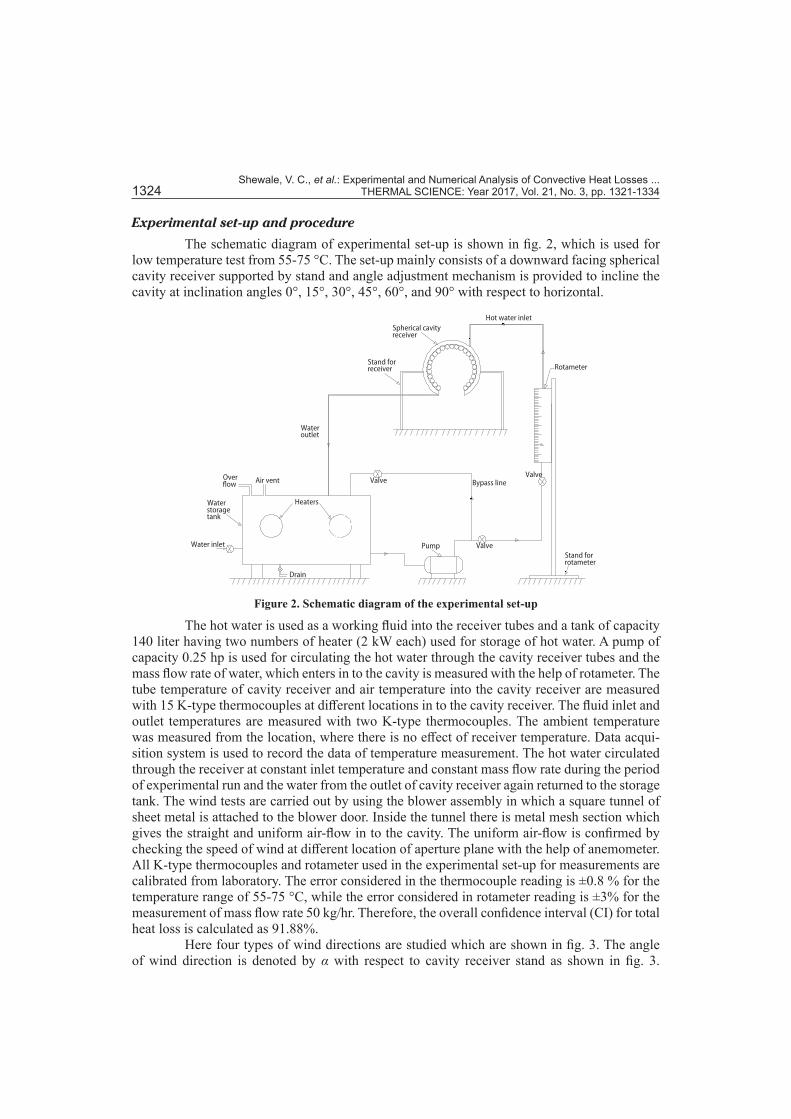
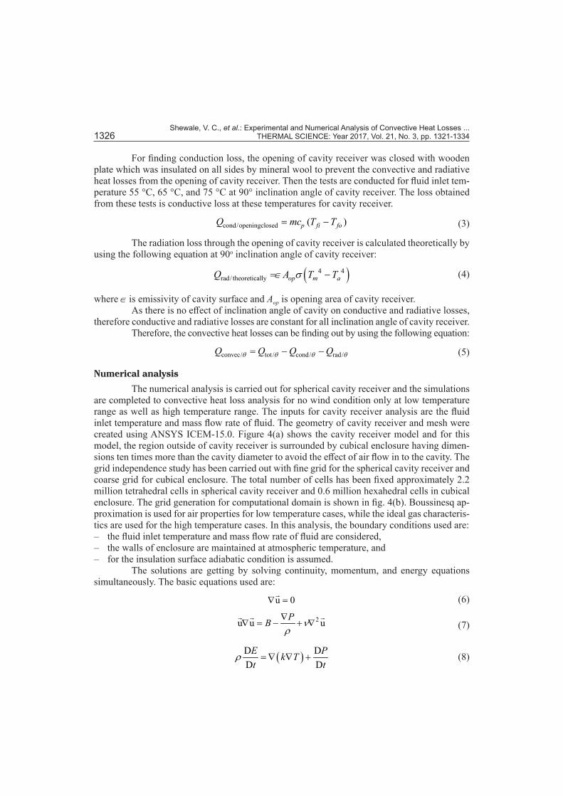
The numerical analysis is carried out for spherical cavity receiver and the simulations are completed to convective heat loss analysis for no wind condition only at low temperature range as well as high temperature range. The inputs for cavity receiver analysis are the fluid inlet temperature and mass flow rate of fluid. The geometry of cavity receiver and mesh were created using ANSYS ICEM-15.0. Figure 4(a) shows the cavity receiver model and for this model, the region outside of cavity receiver is surrounded by cubical enclosure having dimen-sions ten times more than the cavity diameter to avoid the effect of air flow in to the cavity. The grid independence study has been carried out with fine grid for the spherical cavity receiver and coarse grid for cubical enclosure. The total number of cells has been fixed approximately 2.2 million tetrahedral cells in spherical cavity receiver and 0.6 million hexahedral cells in cubical enclosure. The grid generation for computational domain is shown in fig. 4(b). Boussinesq ap-proximation is used for air properties for low temperature cases, while the ideal gas characteris-tics are used for the high temperature cases. In this analysis, the boundary conditions used are: – the fluid inlet temperature and mass flow rate of fluid are considered, – the walls of enclosure are maintained at atmospheric temperature, and – for the insulation surface adiabatic condition is assumed.
The solutions are getting by solving continuity, momentum, and energy equations simultaneously. The basic equations used are:
u 0∇ = (6)
2u u uPB νρ∇
∇ = − + ∇
(7)
( )D DD D
E Pk Tt t
ρ = ∇ ∇ + (8)
Shewale, V. C., et al.: Experimental and Numerical Analysis of Convective Heat Losses ... THERMAL SCIENCE: Year 2017, Vol. 21, No. 3, pp. 1321-1334 1327
The steady-state and 3-D governing equations are solved in ANSYS FLUENT 15 using an implicit solver. For pressure velocity coupling, semi-implicit pressure linked equation SIMPLE algorithm has been used. The discretization of momentum and energy was carried out using first order upwind scheme. The minimum convergence criteria were set at 10–3 for conti-nuity and velocity equations and 10–6 for energy equation. To obtain the heat transfer and flow solutions, the solver undertakes the iteration until the convergence criteria is satisfied.
Results and discussion
Experimental results
The experimental results of combined radiative, convective and conductive heat losses for no wind condition at 55 °C, 65 °C, and 75 °C temperatures and convective heat loss for no wind and wind conditions are discussed. The experimental convective heat loss for no wind con-dition is compared with the numerical results and Nusselt number correlation is developed based on the experimental data. The experiment is also carried out to study the convective heat losses for different wind speeds and different wind directions. Due to temperature drop from inlet to outlet of cavity, the wall temperature is not completely at uniform temperature. Two wind speeds (3 m/s and 5 m/s) and four wind directions with respect to cavity receiver stand [α = 0° (side-on wind), 30°, 60°, 90° (head-on wind)] are used for studying the effect of wind speed and wind direction on convective heat losses. It is found that as the wind speed increases, the convective heat losses are increased and higher than the heat losses obtained from no wind condition.
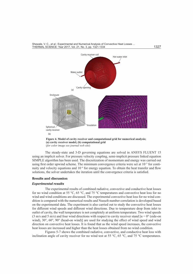
Figures 5-7 shows the combined radiative, convective, and conductive heat loss with inclination angle of cavity receiver for no wind test at 55 °C, 65 °C, and 75 °C temperatures.
Figure 4. Model of cavity receiver and computational grid for numerical analysis; (a) cavity receiver model, (b) computational grid(for color image see journal web site)
(a)
(b)
Hot water inlet
Water outlet
Cavity receiver coil
Cavity opening
Spherical cavity receiver
Insulation
Enclosure
Shewale, V. C., et al.: Experimental and Numerical Analysis of Convective Heat Losses ... 1328 THERMAL SCIENCE: Year 2017, Vol. 21, No. 3, pp. 1321-1334
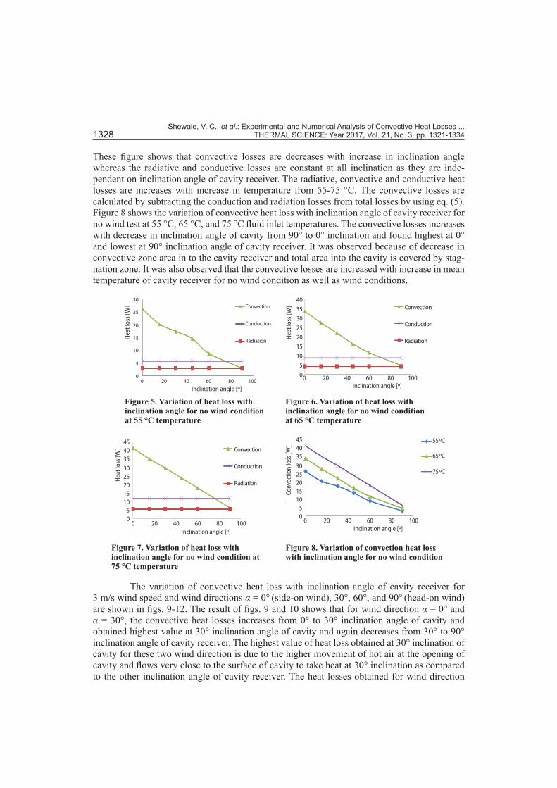
These figure shows that convective losses are decreases with increase in inclination angle whereas the radiative and conductive losses are constant at all inclination as they are inde-pendent on inclination angle of cavity receiver. The radiative, convective and conductive heat losses are increases with increase in temperature from 55-75 °C. The convective losses are calculated by subtracting the conduction and radiation losses from total losses by using eq. (5). Figure 8 shows the variation of convective heat loss with inclination angle of cavity receiver for no wind test at 55 °C, 65 °C, and 75 °C fluid inlet temperatures. The convective losses increases with decrease in inclination angle of cavity from 90° to 0° inclination and found highest at 0° and lowest at 90° inclination angle of cavity receiver. It was observed because of decrease in convective zone area in to the cavity receiver and total area into the cavity is covered by stag-nation zone. It was also observed that the convective losses are increased with increase in mean temperature of cavity receiver for no wind condition as well as wind conditions.
Figure 7. Variation of heat loss with inclination angle for no wind condition at 75 °C temperature
Inclination angle [º]0 20 40 60 80 100
454035
3025201510
50
Hea
t los
s [W
] Convection
Conduction
Radiation
Figure 8. Variation of convection heat loss with inclination angle for no wind condition
Inclination angle [º]0 20 40 60 80 100
454035
3025201510
50
Conv
ectio
n lo
ss [W
]
55 ºC
65 ºC
75 ºC
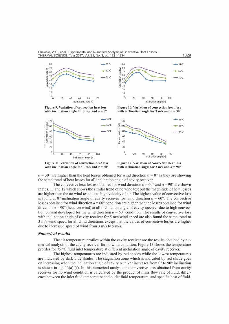
The variation of convective heat loss with inclination angle of cavity receiver for 3 m/s wind speed and wind directions α = 0° (side-on wind), 30°, 60°, and 90° (head-on wind) are shown in figs. 9-12. The result of figs. 9 and 10 shows that for wind direction α = 0° and α = 30°, the convective heat losses increases from 0° to 30° inclination angle of cavity and obtained highest value at 30° inclination angle of cavity and again decreases from 30° to 90° inclination angle of cavity receiver. The highest value of heat loss obtained at 30° inclination of cavity for these two wind direction is due to the higher movement of hot air at the opening of cavity and flows very close to the surface of cavity to take heat at 30° inclination as compared to the other inclination angle of cavity receiver. The heat losses obtained for wind direction
Figure 6. Variation of heat loss with inclination angle for no wind condition at 65 °C temperature
Inclination angle [º]0 20 40 60 80 100
40
35
30
25
20
15
10
5
0
Hea
t los
s [W
] Convection
Conduction
Radiation
Figure 5. Variation of heat loss with inclination angle for no wind condition at 55 °C temperature
Inclination angle [º]0 20 40 60 80 100
Convection
Conduction
Radiation
30
25
20
15
10
5
0
Hea
t los
s [W
]
Shewale, V. C., et al.: Experimental and Numerical Analysis of Convective Heat Losses ... THERMAL SCIENCE: Year 2017, Vol. 21, No. 3, pp. 1321-1334 1329
α = 30° are higher than the heat losses obtained for wind direction α = 0° as they are showing the same trend of heat losses for all inclination angle of cavity receiver.
The convective heat losses obtained for wind direction α = 60° and α = 90° are shown in figs. 11 and 12 which shows the similar trend of no wind test but the magnitude of heat losses are higher than the no wind test due to high velocity of air. The highest value of convective loss is found at 0° inclination angle of cavity receiver for wind direction α = 60°. The convective losses obtained for wind direction α = 60° condition are higher than the losses obtained for wind direction α = 90° (head-on wind) at all inclination angle of cavity receiver due to high convec-tion current developed for the wind direction α = 60° condition. The results of convective loss with inclination angle of cavity receiver for 5 m/s wind speed are also found the same trend to 3 m/s wind speed for all wind directions except that the values of convective losses are higher due to increased speed of wind from 3 m/s to 5 m/s.
Numerical results
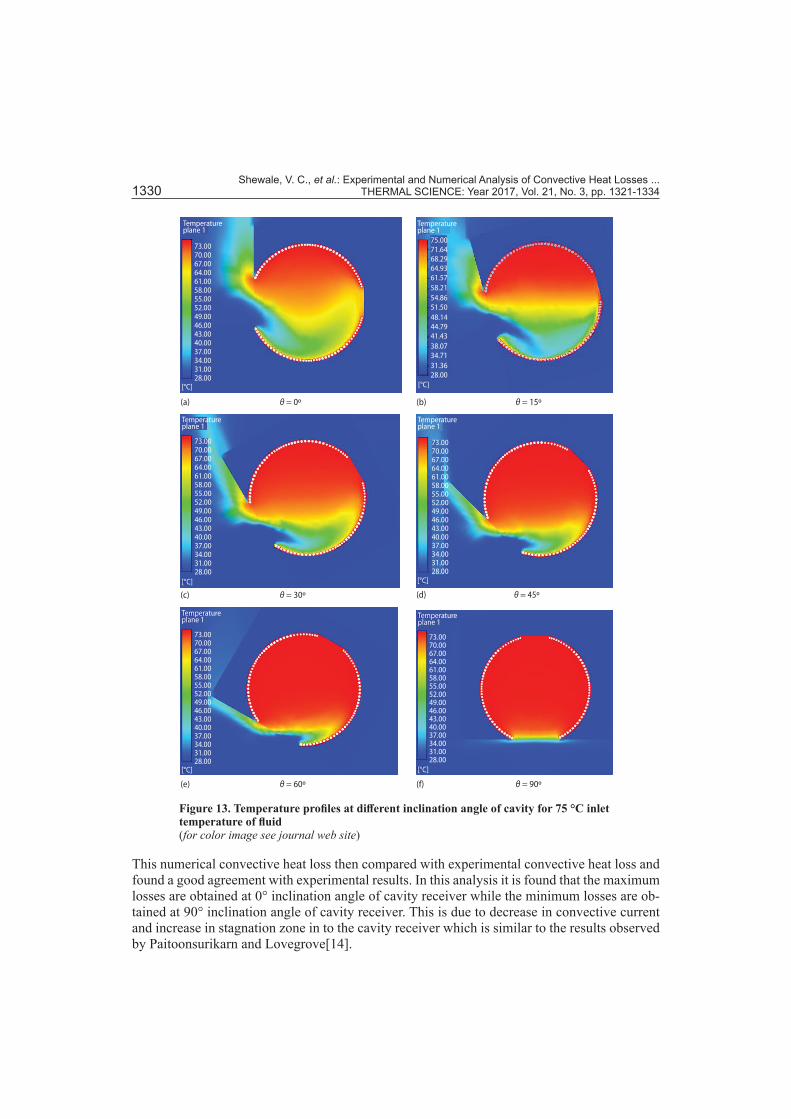
The air temperature profiles within the cavity receiver are the results obtained by nu-merical analysis of the cavity receiver for no wind condition. Figure 13 shows the temperature profiles for 75 °C fluid inlet temperature at different inclination angle of cavity receiver.
The highest temperatures are indicated by red shades while the lowest temperatures are indicated by dark blue shades. The stagnation zone which is indicated by red shade goes on increasing when the inclination angle of cavity receiver increases from 0° to 90° inclination is shown in fig. 13(a)-(f). In this numerical analysis the convective loss obtained from cavity receiver for no wind condition is calculated by the product of mass flow rate of fluid, differ-ence between the inlet fluid temperature and outlet fluid temperature, and specific heat of fluid.
Figure 9. Variation of convection heat loss with inclination angle for 3 m/s and α = 0°
Inclination angle [º]0 20 40 60 80 100
80
70
60
50
40
30
20
10
0
Conv
ectio
n lo
ss [W
]
55 ºC
65 ºC
75 ºC
Figure 10. Variation of convection heat loss with inclination angle for 3 m/s and α = 30°
Inclination angle [º]0 20 40 60 80 100
908070605040302010
0
Conv
ectio
n lo
ss [W
]
55 ºC
65 ºC
75 ºC
Figure 11. Variation of convection heat loss with inclination angle for 3 m/s and α = 60°
Inclination angle [º]0 20 40 60 80 100
120
100
80
60
40
20
0
Conv
ectio
n lo
ss [W
]
55 ºC
65 ºC
75 ºC
Figure 12. Variation of convection heat loss with inclination angle for 3 m/s and α = 90°
Inclination angle [º]0 20 40 60 80 100
120
100
80
60
40
20
0
Conv
ectio
n lo
ss [W
]55 ºC
65 ºC
75 ºC
Shewale, V. C., et al.: Experimental and Numerical Analysis of Convective Heat Losses ... 1330 THERMAL SCIENCE: Year 2017, Vol. 21, No. 3, pp. 1321-1334
This numerical convective heat loss then compared with experimental convective heat loss and found a good agreement with experimental results. In this analysis it is found that the maximum losses are obtained at 0° inclination angle of cavity receiver while the minimum losses are ob-tained at 90° inclination angle of cavity receiver. This is due to decrease in convective current and increase in stagnation zone in to the cavity receiver which is similar to the results observed by Paitoonsurikarn and Lovegrove[14].
Figure 13. Temperature profiles at different inclination angle of cavity for 75 °C inlet temperature of fluid(for color image see journal web site)
Shewale, V. C., et al.: Experimental and Numerical Analysis of Convective Heat Losses ... THERMAL SCIENCE: Year 2017, Vol. 21, No. 3, pp. 1321-1334 1331
Correlation developed
The Nusselt number is calculated to the values of convective losses for no wind con-dition to develop the correlation of Nusselt number. The fluid inlet temperatures of 55-75 °C are used to calculate the Nusselt number for all inclination angle of cavity receiver:
Nu oph dk
= (9)
where hop is the heat transfer coefficient based on opening area, d – the opening diameter of cav-ity receiver, and k – the thermal conductivity which is taken at average temperature of Tm and Ta.
The heat transfer coefficient based on the opening area of cavity receiver is given by the equation:
( )
convec/op
m a op
QhT T A
θ=−
(10)
where Qconvec/θ is the convective heat loss at cavity inclination θ and Aop is opening area of cavity receiver. It is noticed that the Nusselt number goes on increasing with decrease in inclination angle of cavity receiver. The highest Nusselt number is found at 0° inclination angle of cavity receiver while the lowest Nusselt number is found at 90° inclination angle of cavity receiver. The Nusselt number correlation is found to be:
( )1.15
2.710.42Nu 0.041Gr 1 cos m
a
TT
θ−
= +
(11)
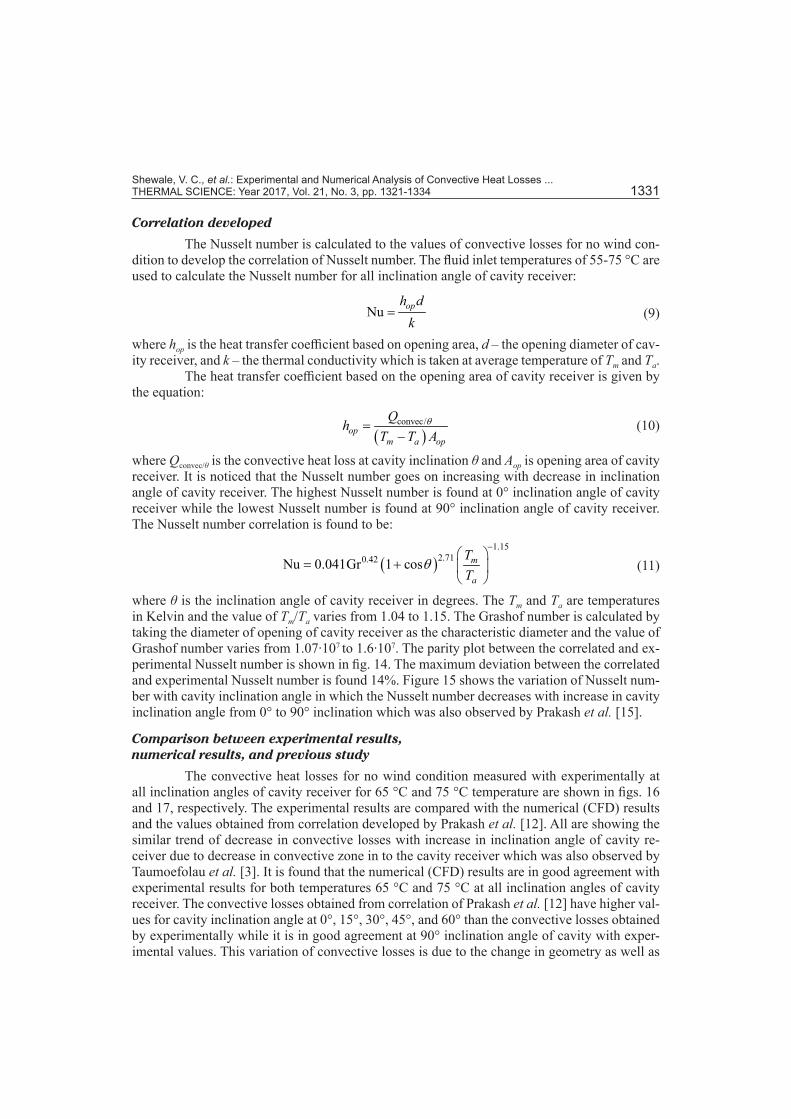
where θ is the inclination angle of cavity receiver in degrees. The Tm and Ta are temperatures in Kelvin and the value of Tm/Ta varies from 1.04 to 1.15. The Grashof number is calculated by taking the diameter of opening of cavity receiver as the characteristic diameter and the value of Grashof number varies from 1.07∙107 to 1.6∙107. The parity plot between the correlated and ex-perimental Nusselt number is shown in fig. 14. The maximum deviation between the correlated and experimental Nusselt number is found 14%. Figure 15 shows the variation of Nusselt num-ber with cavity inclination angle in which the Nusselt number decreases with increase in cavity inclination angle from 0° to 90° inclination which was also observed by Prakash et al. [15].
Comparison between experimental results, numerical results, and previous study
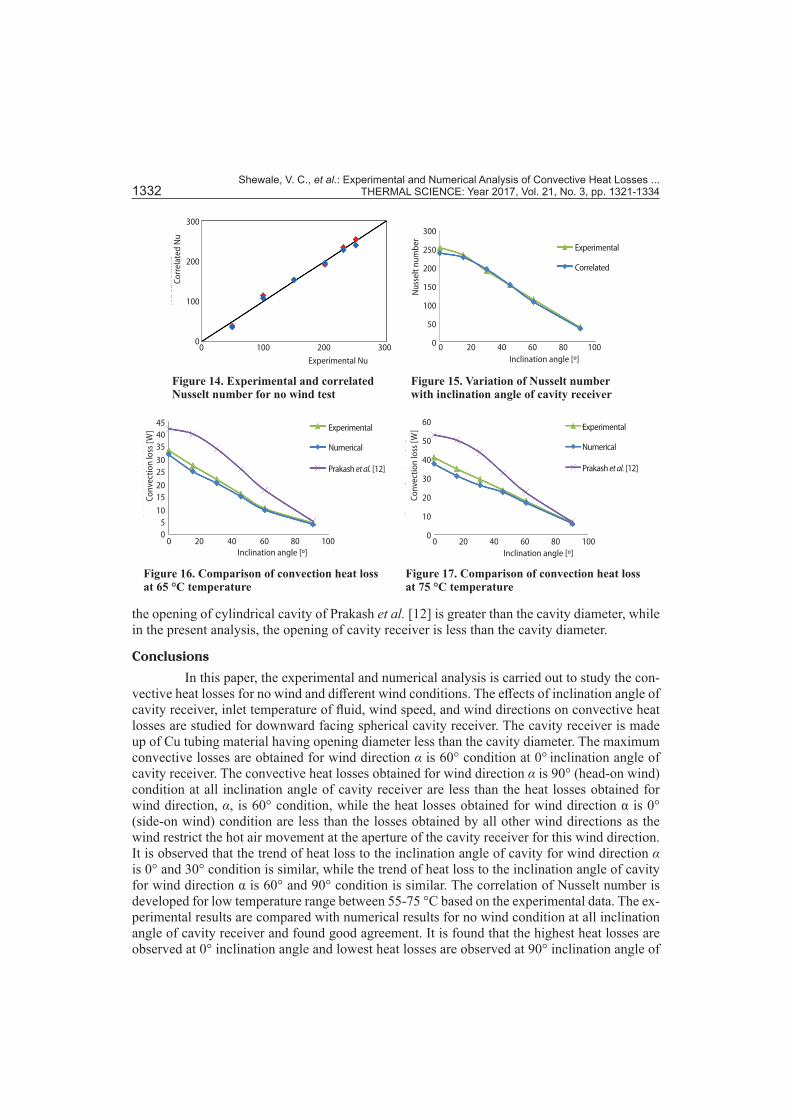
The convective heat losses for no wind condition measured with experimentally at all inclination angles of cavity receiver for 65 °C and 75 °C temperature are shown in figs. 16 and 17, respectively. The experimental results are compared with the numerical (CFD) results and the values obtained from correlation developed by Prakash et al. [12]. All are showing the similar trend of decrease in convective losses with increase in inclination angle of cavity re-ceiver due to decrease in convective zone in to the cavity receiver which was also observed by Taumoefolau et al. [3]. It is found that the numerical (CFD) results are in good agreement with experimental results for both temperatures 65 °C and 75 °C at all inclination angles of cavity receiver. The convective losses obtained from correlation of Prakash et al. [12] have higher val-ues for cavity inclination angle at 0°, 15°, 30°, 45°, and 60° than the convective losses obtained by experimentally while it is in good agreement at 90° inclination angle of cavity with exper-imental values. This variation of convective losses is due to the change in geometry as well as
Shewale, V. C., et al.: Experimental and Numerical Analysis of Convective Heat Losses ... 1332 THERMAL SCIENCE: Year 2017, Vol. 21, No. 3, pp. 1321-1334
the opening of cylindrical cavity of Prakash et al. [12] is greater than the cavity diameter, while in the present analysis, the opening of cavity receiver is less than the cavity diameter.
Conclusions
In this paper, the experimental and numerical analysis is carried out to study the con-vective heat losses for no wind and different wind conditions. The effects of inclination angle of cavity receiver, inlet temperature of fluid, wind speed, and wind directions on convective heat losses are studied for downward facing spherical cavity receiver. The cavity receiver is made up of Cu tubing material having opening diameter less than the cavity diameter. The maximum convective losses are obtained for wind direction α is 60° condition at 0° inclination angle of cavity receiver. The convective heat losses obtained for wind direction α is 90° (head-on wind) condition at all inclination angle of cavity receiver are less than the heat losses obtained for wind direction, α, is 60° condition, while the heat losses obtained for wind direction α is 0° (side-on wind) condition are less than the losses obtained by all other wind directions as the wind restrict the hot air movement at the aperture of the cavity receiver for this wind direction. It is observed that the trend of heat loss to the inclination angle of cavity for wind direction α is 0° and 30° condition is similar, while the trend of heat loss to the inclination angle of cavity for wind direction α is 60° and 90° condition is similar. The correlation of Nusselt number is developed for low temperature range between 55-75 °C based on the experimental data. The ex-perimental results are compared with numerical results for no wind condition at all inclination angle of cavity receiver and found good agreement. It is found that the highest heat losses are observed at 0° inclination angle and lowest heat losses are observed at 90° inclination angle of
Figure 14. Experimental and correlated Nusselt number for no wind test
Experimental Nu
0 100 200 300
300
200
100
0
Cor
rela
ted
Nu
Figure 15. Variation of Nusselt number with inclination angle of cavity receiver
Inclination angle [º]0 20 40 60 80 100
Experimental
Correlated
300
250
200
150
100
50
0
Nus
selt
num
ber
Figure 16. Comparison of convection heat loss at 65 °C temperature
Inclination angle [º]0 20 40 60 80 100
Experimental
Numerical
Prakash et al. [12]
454035
3025
2015
1050
Conv
ectio
n lo
ss [W
]
Figure 17. Comparison of convection heat loss at 75 °C temperature
Inclination angle [º]0 20 40 60 80 100
60
50
40
30
20
10
0
Conv
ectio
n lo
ss [W
] Experimental
Numerical
Prakash et al. [12]
Shewale, V. C., et al.: Experimental and Numerical Analysis of Convective Heat Losses ... THERMAL SCIENCE: Year 2017, Vol. 21, No. 3, pp. 1321-1334 1333
cavity receiver for no wind conditions. It is also found that as the mean temperature of cavity receiver increases, the heat losses of cavity receiver are also increases for no wind as well as all wind conditions.
Nomenclature
Aop – opening area of cavity receiver, [m2]B – body force per unit volume, [Nm–3]cp – specific heat of working fluid, [kJkg–1K–1]D – diameter of cavity receiver, [m]d – opening diameter of cavity receiver, [m]E – energy per unit volume, [Jm–3]Gr – Grashof number, [–]hop – heat transfer coefficient based on opening
area of cavity, [Wm–2K–1]k – thermal conductivity, [Wm–1K–1]m – mass flow rate of water, [kgs–1]Nu – Nusselt number ,[–]P – pressure, [Nm–2]Qtot/θ – total heat loss at cavity receiver angle θ, [W]Qcond/θ – conduction heat loss at cavity receiver
angle θ, [W]Qconvec/θ – convection heat loss at cavity receiver
angle θ, [W]Qrad/θ – radiation heat loss at cavity receiver
angle θ, [W] Qcond/openingclosed – conduction heat loss for no wind
test at 90o angle when opening is closed, [W]
Qrad/theoretically – radiation heat loss at 90o cavity inclination angle obtained theoretically, [W]
Ta – atmospheric temperature, [oC]Tm – mean temperature of working
fluid [= 0.5(Tfi + Tfo)], [oC]Tfi – inlet temperature of working
fluid entering the receiver, [oC]Tfo – outlet temperature of working fluid leaving
the receiver, [oC]t – time, [s]u
– velocity vector, [ms–1]
Greek symbols
α – angle of wind direction with respect to receiver stand, [º]
References[1] Clausing, A. M., An Analysis of Convective Losses from Cavity Solar Central Receivers, Solar Energy,
27 (1981), 4, pp. 295-300[2] Harris, J. A., Lenz, T. G., Thermal Performance of Concentrator/Cavity Receiver Systems, Solar Energy,
34 (1985), 2, pp. 135-142[3] Taumoefolau, T., et al., Experimental Investigation of Natural Convection Heat Loss from Solar Concen-
trator Cavity Receiver, J. Solar Energy Eng., 126 (2004), 2, pp. 801-807[4] Leibfried, U., Ortjohann, J., Convective Heat Loss from Upward and Downward-Facing Cavity Solar
Receivers: Measurements and Calculations, J. Solar Energy Eng., 117 (1995), 2, pp. 75-84[5] Stine, W. B., McDonald, C. G., Cavity Receiver Heat Loss Measurements, Proceeding, Int. Solar Energy
Society World Congress, Kobe, Japan, 1989, pp. 1318-1322[6] Jilte, R. D., et al., Natural Convection and Radiation Heat Loss from Open Cavities of Different Shapes
and Sizes Used with Dish Concentrator, Mech. Eng. Reasearch, 3 (2013), 1, pp. 25-43[7] Koenig, A. A., Marvin, M., Convection Heat Loss Sensitivity in Open Cavity Solar Receivers, Final re-
port, DOE Contract No: EG77-C-04–3985, US Department of Energy, Oak Ridge, Tenn., USA, 1981[8] Prakash, M., et al., Determination of Stagnation and Convective Zones in a Solar Cavity Receiver, Int. J.
Therm. Sci., 49 (2010), 4, pp. 680-691[9] Clausing, A. M., Convective Losses from Cavity Solar Receivers-Comparisons between Analytical Pre-
dictions and Experimental Results, J. Solar Energy Eng., 105 (1983), 1, pp. 29-33[10] Quere, P., et al., Experimental Study of Heat Loss through Natural Convection from an Isothermal Cubic
Open Cavity, Report SAND81-8014, Sandia National Laboratory, Livermore, Cal., USA, 1981[11] Sendhil Kumar, N., Reddy, K. S., Comparison of Receivers for Solar Dish Collector System, Energy
Conver. Manag., 49 (2008), 4, pp. 812-819[12] Prakash, M., et al., Investigations on Heat Losses from a Solar Cavity Receiver, Solar Energy, 83 (2009),
2, pp. 157-170
Shewale, V. C., et al.: Experimental and Numerical Analysis of Convective Heat Losses ... 1334 THERMAL SCIENCE: Year 2017, Vol. 21, No. 3, pp. 1321-1334
[13] Ma, R. Y, Wind Effects on Convective Heat Loss from a Cavity Receiver for a Parabolic Concentrating Solar Collector, Report SAND92-7293, Sandia National Laboratory, Livermore, Cal., USA, 1993
[14] Paitoonsurikarn, S., Lovegrove, K., Numerical Investigation of Natural Convection Loss in Cavity-Type Solar Receivers, Proceedings, ANZSES Annual Conference, Newcastle, Australia, 2002
[15] Prakash, M., et al., Numerical Study of Natural Convection Loss from Opens Cavities, Int. J. Therm. Sci., 51 (2012), Jan., pp. 23-30
[16] Hess, C. F., Henze, R. H., Experimental Investigations of Natural Convection Losses from Open Cavities, J. Heat Trans., 106 (1984), 2, pp. 333-338
[17] Chan, Y. L., Tien, C. L., A Numerical Study of Two-Dimensional Laminar Natural Convection in Shallow Open Cavities, Int. J. Heat Mass Trans., 28 (1985), 3, pp. 603-612
[18] Reddy, K. S., et al., Numerical Investigation of Energy Efficient Receiver for Solar Parabolic trough Con-centrator, J. Heat Trans., 29 (2008), 11, pp. 961-972
[19] Paitoonsurikarn, S., Lovegrove, K., On the Study of Convection Loss from Open Cavity Receivers in Solar Paraboloidal Dish Application, Proceedings, Solar 2003, ANZSES Annual Conference, Melbourne, Australia, 2003
[20] McDonald, C. G., Heat Loss from an Open Cavity, Report SAND95-2939, Sandia National Laboratory, Livermore, Cal., USA, 1995
[21] Sendhil Kumar, N., Reddy, K. S., Numerical Investigation of Natural Convection Heat Loss in Modified Cavity Receiver for Fuzzy Focal Solar Dish Concentrator, Solar Energy, 81 (2007), 7, pp. 846-855
[22] Reddy, K. S., Sendhil Kumar, N., Combined Laminar Natural Convection and Surface Radiation Heat Transfer in a Modified Cavity Receiver of Solar Parabolic Dish, Int. J. Therm. Sci., 47 (2008), 12, pp. 1647-1657
[23] Wu, S. Y., et al., Experimental Investigation on Heat Loss of a Fully Open Cylindrical Cavity with Differ-ent Boundary Conditions, Exp. Therm. Fluid Sci., 45 (2013), Feb., pp. 92-101
Paper submitted: June 1, 2015Paper revised: September 29, 2015Paper accepted: September 29, 2015