185 Experimental and Numerical Study of an Anti-Sloshing Floating Device for Membrane-Type LNG Tanks by Makoto Arai, Member Ryosuke Suzuki, Member Naohiko Kishimoto, Member Takahiro Ando, Member Summary Recent developments with offshore terminals and floating liquefied natural gas production, storage and offloading (FLNG) applications have included the new requirement that the storage tanks be able to handle unrestricted filling with LNG. If membrane-type tanks are used in such new systems, the occurrence of sloshing in the half-load condition becomes one of the most important design issues. In this paper, we propose a simple anti-sloshing floating device to be installed inside a liquid cargo tank. By setting the device on the free surface of the liquid cargo, the original free surface is divided into two or more sub-surfaces, and resonant sloshing of the liquid can be avoided by changing the natural frequency of its motion. This floating device can follow the liquid height change in the tank during loading and unloading operations of the liquid cargo, a feature that is especially preferable in FLNG applications. We examine the performance of the proposed anti-sloshing device by a series of model experiments and numerical simulations, which indicate that the device's performance is very promising. 1. Floating LNG (FLNG) FLNG FLNG LNG 1) ) LNG FLNG 2. * ** *** **** 浮体を用いた LNG タンクのスロッシング防止に関する研究 正会員 荒 井 誠 * 正会員 鈴 木 良 介 ** 正会員 岸 本 直 彦 *** 正会員 安 藤 孝 弘 **** 原稿受理 平成 25 年 2 月 27 日
Transcript
浮体を用いた LNG タンクのスロッシング防止に関する研究 185
LNG
* ** *** ****
Experimental and Numerical Study of an Anti-Sloshing Floating Device for Membrane-Type LNG Tanks by Makoto Arai, Member Ryosuke Suzuki, Member Naohiko Kishimoto, Member Takahiro Ando, Member
Summary
Recent developments with offshore terminals and floating liquefied natural gas production, storage and offloading (FLNG)
applications have included the new requirement that the storage tanks be able to handle unrestricted filling with LNG. If membrane-type tanks are used in such new systems, the occurrence of sloshing in the half-load condition becomes one of the most important design issues. In this paper, we propose a simple anti-sloshing floating device to be installed inside a liquid cargo tank. By setting the device on the free surface of the liquid cargo, the original free surface is divided into two or more sub-surfaces, and resonant sloshing of the liquid can be avoided by changing the natural frequency of its motion. This floating device can follow the liquid height change in the tank during loading and unloading operations of the liquid cargo, a feature that is especially preferable in FLNG applications. We examine the performance of the proposed anti-sloshing device by a series of model experiments and numerical simulations, which indicate that the device's performance is very promising.
1.
Floating LNG (FLNG) FLNG
FLNGLNG
1) )
LNG
FLNG
2.
***
*******
25 2 28
浮体を用いた LNG タンクのスロッシング防止に関する研究
正会員 荒 井 誠* 正会員 鈴 木 良 介**
正会員 岸 本 直 彦*** 正会員 安 藤 孝 弘****
原稿受理 平成 25 年 2 月 27 日
日本船舶海洋工学会論文集 第 17 号 2013 年 6 月 186
2. 1
Fig.1 ( )
Fig. 1 Excitation generator.
900mm 600mm225mm 2
50mm 50mm 0.5
Fig.2I
3 I T2 5
Table 1 2
2
Fig. 2 Floating bodies.
Table 1 Dimensions of floating bodies. Float type I-1 I-2 I-3 T-1 T-2
Fig. 11 Comparison of the amplitude of liquid surface motion between one float and two floats cases
(Type I-1, h=50%D, =1deg., d=75 mm, yc=150 mm).
(a) U-tube mode (0.74Hz) (b) 1st mode (1.72Hz)
Fig. 12 Free surface deformation with multiple floats (Type I-1, two floats, h=50%D, =1deg., d=75 mm, yc=150 mm)
4. 2
Fig.13 70% I-1
5.96m 8.35
Fig.13
Fig.14 Fig.13Fig.14
(a) Without float
(b) With float Fig. 13 Change of liquid surface displacement in time
(Experiment, type I float, d=50mm, h=70%D).
(a) Without float
(b) With float Fig. 14 Change of liquid surface displacement in time (Numerical simulation, Type I float, d=50mm, h=70%D).
3
2
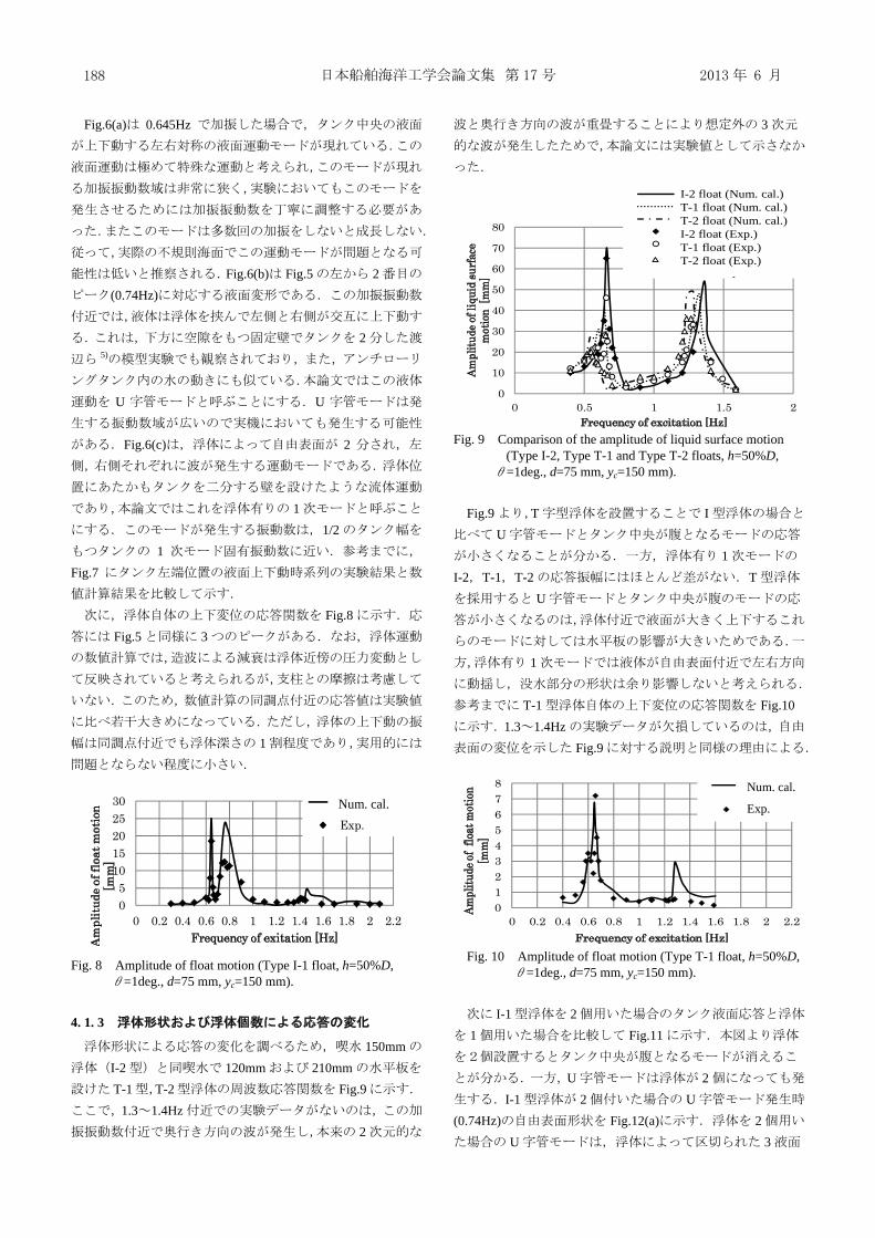
Fig.9 1.3 1.4Hz
0
10
20
30
40
50
60
70
0 0.2 0.4 0.6 0.8 1 1.2 1.4 1.6 1.8 2 2.2
Am
plitu
de o
f liq
uid
surf
ace
mot
ion
[ mm
]
Frequency of exitation [hz]
the No. of float=1 (Num.Cathe No. of float=2 (Num.Cathe No. of float=1 (Exp.)the No. of float=2 (Exp.)
No. of float=1 (Num. cal.)No. of float=2 (Num. cal.)No. of float=1 (Exp.)No. of float=2 (Exp.)
日本船舶海洋工学会論文集 第 17 号 2013 年 6 月 190
5. 5. 1
Table 2 Dimensions of tank and float.
Tank breadth, B 60.0m 60.0m Tank height, D 40.0m 40.0m Initial liquid level, h 20.0m(50%) 20.0m(50%)
Center of rotation (xc,zc)[m] (30.0,10.0) (30.0,10.0)
Float breadth, b 4.0m Float draft, d 5.0m
Fig. 15 Relation between RAO of liquid surface motion and frequency of sea waves.
4
FLNGFLNG
FLNG
Walden 6)
60% 0.091Hz 0.14HzFig.15
critical frequencyTable 2
50% Fig.151
1
U
5. 2
5. 2. 1
FLNG
FLNG 7), 8) Table 3FLNG
Fig.16 VLCCFig.16
LNG3
1.5m 85m9)
Table 3 Principal dimensions of the designed ship in full load
condition.
Length between perpendiculars, Lpp 340m
Breadth, B 65m
Draft, d 15.5m
Displaced volume, V 2.9×10⁵m3
Fig. 16 Loading condition of LNG tanks.
5.96m
10.16sec (6) ISSC
(6)
10),11)
5. 3
} /2exp{-0.44/ ) 2
(2
0.11)( 45-2 TTTH VVVV
02468
1012141618
0 0.05 0.1 0.15 0.2 0.25
Am
plitu
de o
f liq
uid
s urf
ace
mot
ion
[m]
Frequency of excitation [Hz]
No floats
With a float
Critical frequency
Without float
With float
浮体を用いた LNG タンクのスロッシング防止に関する研究 191
Table 250%
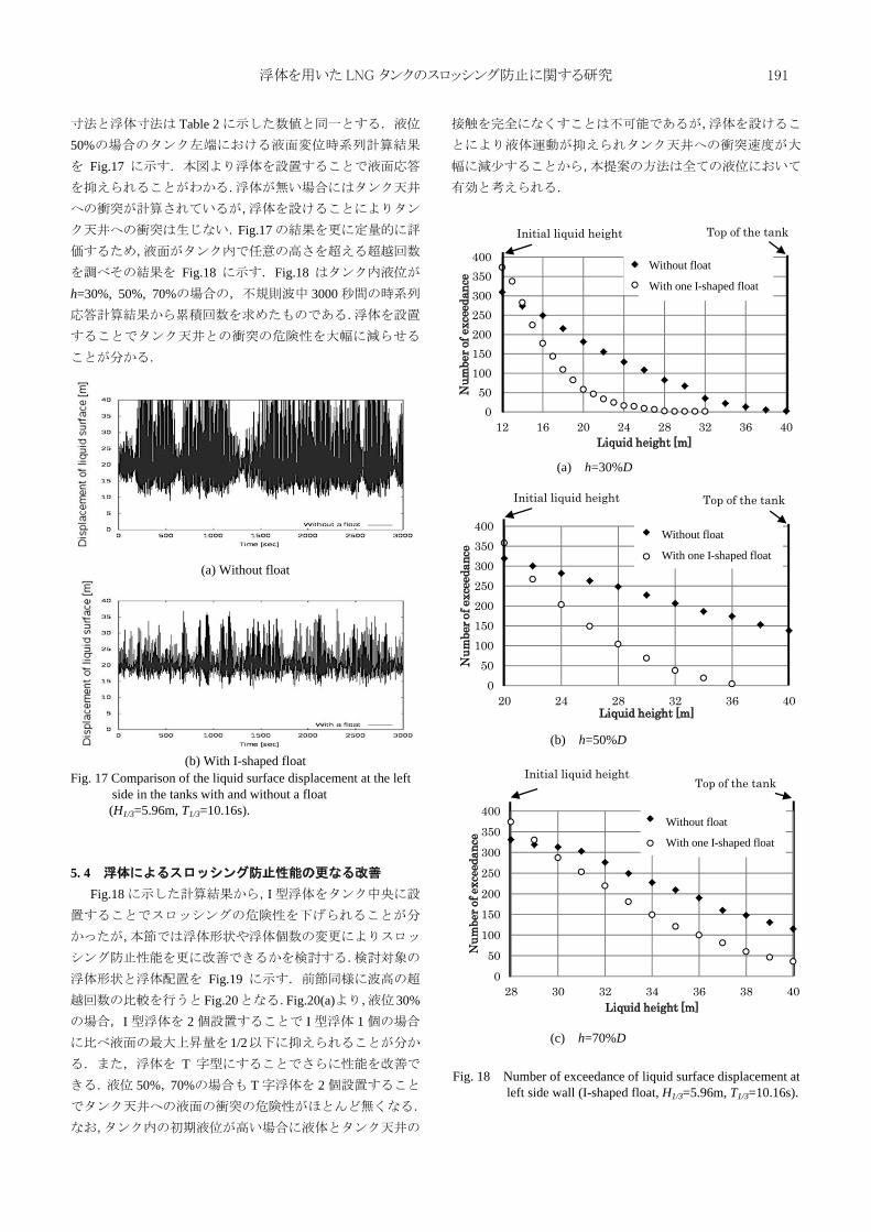
Fig.17
Fig.17
Fig.18 Fig.18h=30%, 50%, 70% 3000
(a) Without float
(b) With I-shaped float Fig. 17 Comparison of the liquid surface displacement at the left
side in the tanks with and without a float (H1/3=5.96m, T1/3=10.16s).
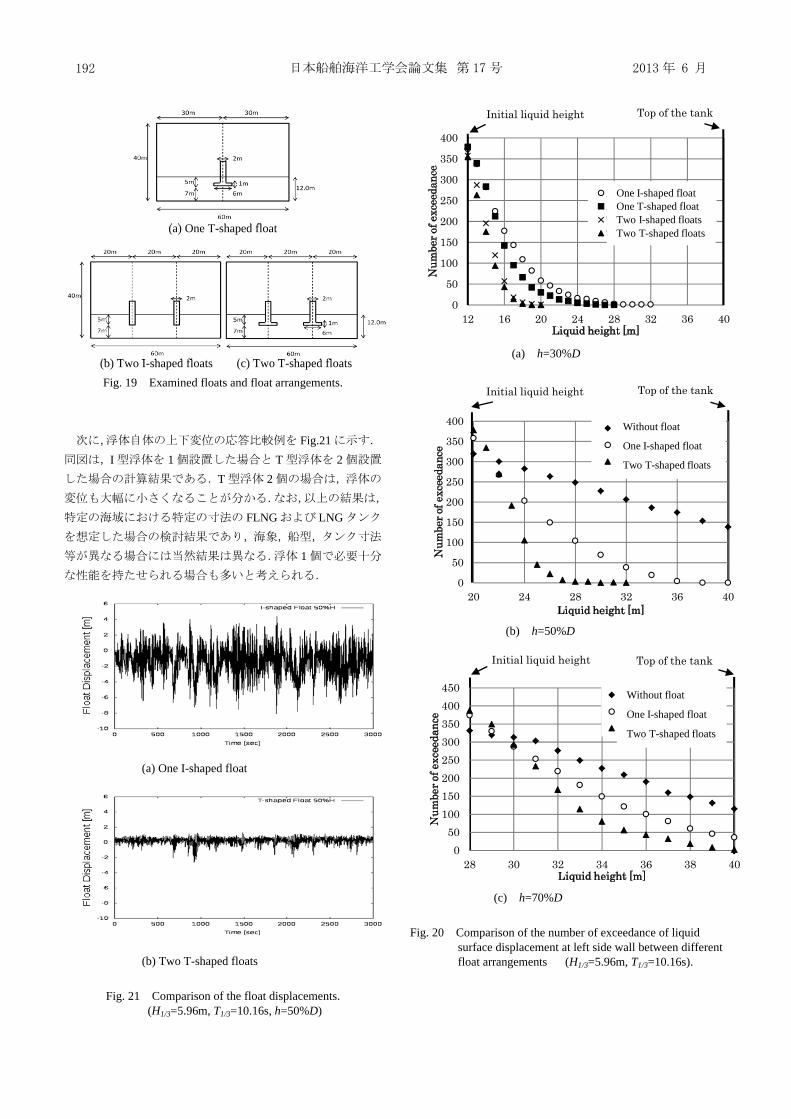
5. 4 Fig.18 I
Fig.19Fig.20 Fig.20(a) 30%
I 2 I 11/2
T50% 70% T 2
(a) h=30%D
(b) h=50%D
(c) h=70%D
Fig. 18 Number of exceedance of liquid surface displacement at left side wall (I-shaped float, H1/3=5.96m, T1/3=10.16s).
050
100150200250300350400
12 16 20 24 28 32 36 40
Num
ber o
f exc
eeda
nce
Liquid height [m]
Without a floatWith an I-shaped float
Top of the tankInitial liquid height
Without float
With one I-shaped float
050
100150200250300350400
20 24 28 32 36 40
Num
ber o
f exc
eeda
nce
Liquid height [m]
Without a float
With an I-shaped float
Top of the tankInitial liquid height
Without float
With one I-shaped float
Initial liquid heightTop of the tank
050
100150200250300350400
28 30 32 34 36 38 40
Num
ber o
f exc
eeda
nce
Liquid height [m]
Without a float
With an I-shaped float
Without float
With one I-shaped float
日本船舶海洋工学会論文集 第 17 号 2013 年 6 月 192
(a) One T-shaped float (b) Two I-shaped floats (c) Two T-shaped floats
Fig. 19 Examined floats and float arrangements.
Fig.21I 1 T 2
T 2
FLNG LNG
1
(a) One I-shaped float (b) Two T-shaped floats
Fig. 21 Comparison of the float displacements. (H1/3=5.96m, T1/3=10.16s, h=50%D)
(a) h=30%D
(b) h=50%D
(c) h=70%D Fig. 20 Comparison of the number of exceedance of liquid
surface displacement at left side wall between different float arrangements (H1/3=5.96m, T1/3=10.16s).
0
50
100
150
200
250
300
350
400
12 16 20 24 28 32 36 40
Num
ber o
f exc
eeda
nce
Liquid height [m]
An I-shaped floatA T-shaped floatTwo I-shaped floatsTwo T-shaped floats
Initial liquid height Top of the tank
One I-shaped floatOne T-shaped floatTwo I-shaped floatsTwo T-shaped floats
Top of the tankInitial liquid height
0
50
100
150
200
250
300
350
400
20 24 28 32 36 40
Num
ber o
f exc
eeda
nce
Liquid height [m]
Without a floatAn I-shaped floatTwo T-shaped floats
Without float
One I-shaped float
Two T-shaped floats
Initial liquid height Top of the tank
050
100150200250300350400450
28 30 32 34 36 38 40
Num
ber o
f exc
eeda
nce
Liquid height [m]
Without a floatAn I-shaped floatTwo T-shaped floats
Without float
One I-shaped float
Two T-shaped floats
浮体を用いた LNG タンクのスロッシング防止に関する研究 193
6.
1) Arai, M, Bogaert, H., Graczyk, M., Ha, M.K., Kim, W.S., Lindgren, M., Martin, E., Noble, P., Tao, L., Valle, O., Xiong, Y.: Report of Committee V.2, Natural Gas Storage and Transportation, Proceedings of 18th International Ship and Offshore Structures Congress, Volume 2, pp. 67-112, 2012.
2) Arai, M., Suzuki, R., Ohta, Y. and Wang, X.: Study of an anti-sloshing floating device for membrane-type LNG tanks, Proceedings of IMDC 2012, 11th International Marine Design Conference, Vol.2, p.p. 554-565, 2012
3) Arai, M., Cheng, L. Y., Kumano, A., Miyamoto, T.: A Technique for Stable Numerical Computation of Hydrodynamic Impact Pressure in Sloshing Simulation, Journal of the Society of Naval Architects, Japan, Vol.191, pp.299-307, 2002.
4) 1975
5)
C 67 657 pp.204-211, 2001
6) 1992
7) FPSO4
, p.p.79-84, 2004 8) - LNG-FPSO -
74 2 p.p.152-161, 2009 9) 4 1983 10) Wang, X. and Arai, M.: A Study on Coupling Effect
between Seakeeping and Sloshing for Membrane-type LNG Carrier, International Journal of Offshore and Polar Engineering, Vol.21, No.2, p.p.1-8, 2011.
11) Wang, X. and Arai, M.: Research on Computational Method of Coupled Ship Motions and Sloshing, Journal of the Japan Society of Naval Architects and ocean Engineers, Vol.14, pp.97-104, 2011.


![Research Article Numerical Simulation of Sloshing in 2D ...Faltinsen [ ]presentedanonlinearnumerical method of D sloshing in tanks. Nakayama and Washizu [ ] adopted the boundary element](https://static.documents.pub/doc/80x56/60fc05338404fc3d24614e3a/research-article-numerical-simulation-of-sloshing-in-2d-faltinsen-presentedanonlinearnumerical.jpg)

