Buenos Aires – 5 to 9 September, 2016 Acoustics for the 21 st Century… PROCEEDINGS of the 22 nd International Congress on Acoustics Structural Acoustics and Vibration (others): Paper ICA2016-602 Experimental characterization of dry friction isolators for shock vibration isolation Diego Francisco Ledezma-Ramirez (a) , Fernando Javier Elizondo-Garza (a) , Pablo Ernesto Tapia-Gonzalez (a) , Adrian García-Mederez (a) . (a) Universidad Autónoma de Nuevo León-Facultad de Ingeniería Mecánica y Eléctrica, México, [email protected]Abstract An overview of the use of shock isolators based on dry friction is briefly presented and the possibilities for the development of a more efficient shock isolation system are discussed. Cable isolators, also known as wire rope are studied. Such isolators present nonlinear stiffness behaviour in different directions, i.e. tension-compression, roll and shear, as well as dry friction damping, and are known for being excellent shock isolators. However, little is known about the actual dynamic behaviour under shock loading. Different commercially available samples are studied for several configurations and load rates. The advantages of the use of cable isolator over a classic linear system with viscous damping is also discussed. The stiffness and damping of these models are quantified experimentally, and then this data is used to validate the estimated shock response. The combination of these two properties in a further mathematical model is suggested for the modelling of dry friction isolators available off the shelf. Keywords: shock isolation, dry friction, damping, vibration isolation.
Transcript
Buenos Aires – 5 to 9 September, 2016 Acoustics for the 21st Century…
PROCEEDINGS of the 22nd International Congress on Acoustics
Structural Acoustics and Vibration (others): Paper ICA2016-602
Experimental characterization of dry friction isolators for shock vibration isolation
Diego Francisco Ledezma-Ramirez(a), Fernando Javier Elizondo-Garza(a), Pablo Ernesto Tapia-Gonzalez(a), Adrian García-Mederez(a).
(a) Universidad Autónoma de Nuevo León-Facultad de Ingeniería Mecánica y Eléctrica, México, [email protected]
Abstract
An overview of the use of shock isolators based on dry friction is briefly presented and the possibilities for the development of a more efficient shock isolation system are discussed. Cable isolators, also known as wire rope are studied. Such isolators present nonlinear stiffness behaviour in different directions, i.e. tension-compression, roll and shear, as well as dry friction damping, and are known for being excellent shock isolators. However, little is known about the actual dynamic behaviour under shock loading. Different commercially available samples are studied for several configurations and load rates. The advantages of the use of cable isolator over a classic linear system with viscous damping is also discussed. The stiffness and damping of these models are quantified experimentally, and then this data is used to validate the estimated shock response. The combination of these two properties in a further mathematical model is suggested for the modelling of dry friction isolators available off the shelf.
22nd International Congress on Acoustics, ICA 2016 Buenos Aires – 5 to 9 September, 2016
Acoustics for the 21st Century…
2
Experimental characterization of dry friction isolators for shock vibration isolation
1 Introduction Undesirable effects as fatigue, noise and wear are common results of transient mechanical vibration and this is particularly important in environments such as military, naval and aerospace applications, where is common to mitigate these effects using vibration isolation. Wire rope, or cable isolators are commonly used in those applications due to their high energy storage and dissipation properties. However, most of the isolation designs based on wire ropes are empirical or based in classic isolation theory, which does not reflect the nonlinear properties typically observed in these isolators.
This paper presents experimental results of dynamic and static tests performed in an arrangement of wire rope isolators. The objective is to provide an insight into the shock isolation properties and the nonlinear stiffness and damping behaviour, in order to propose ideas for a further mathematical model to predict the response of such isolators. The development of a mathematical model will enable future applications in isolation technology, vibration and noise control, particularly aerospace applications i.e. landing gears, unmanned aircraft systems, and avionics.
Wire rope isolators are built using a series of steel strands twisted around a core strand, and the resulting wire rope is arranged in a leaf or helical fashion and present a great capability for energy dissipation due to the friction created between the wire strands as the cable twists when the isolator is loaded and unloaded. An advantage of these isolators is that they can work in tension-compression, shear and torsion scenarios. Apart from the nonlinear Coulomb damping observed in these isolators, they also present nonlinear stiffness characteristics. Figure 1 shows some characteristics of the wire rope isolators. Figure 1(a) shows the isolator used in the tests, however, for the testing, four identical samples were used, as explained later. The construction of wire ropes are demonstrated by Figures 1(b) and (c), whilst Figures (d) and (e) depict an experimentally measured force displacement curve, and the stiffness displacement characteristics, both plots corresponding to the isolator considered in this study. It is clear to see the nonlinear behavior, where the stiffness is reduced up to a point where the effective stiffness is very low. Then, as displacement increases, the isolator hardens. The equilibrium position, at which the isolator is loaded, should be chosen about the lower stiffness region, in order to provide better shock and vibration isolation.
22nd International Congress on Acoustics, ICA 2016 Buenos Aires – 5 to 9 September, 2016
Acoustics for the 21st Century…
3
Figure 1: Characteristics of a wire rope isolator: a) Actual isolator used in the study, b) Winding
directions of rope and wires, c) Cross section of the wire rope, d) Force – Deformation plot and e) Stiffness – Deformation plot.
2 Background One of the first applications of dry friction in the isolation of shocks was conducted by Mercer [1] who designed an optimal isolator based on the principle of adjustable friction, obtaining better results than previous studies where polymers were studied, as Snowdon considered [2]. Molyneux [3] studied the behavior of different arrangements with low stiffness springs with limited displacement ranges for mechanical vibration isolation in aeronautical applications. Eshleman [4, 5] studied the response of different configurations of impact insulators as coil springs, fluids, pneumatics, ring springs and friction dampers demonstrating their high capacity in terms of energy dissipation. Cutchins et al [6] published studies on nonlinear stiffness and damping, in which an analytical model for the description of the hysteresis loop, that is common in systems with nonlinear stiffness, was derived. This study focused on the wire springs, the authors noted that the spring wire strands tend to separate when compressing, while when tensioned a greater
22nd International Congress on Acoustics, ICA 2016 Buenos Aires – 5 to 9 September, 2016
Acoustics for the 21st Century…
4
number of contact points exist and the resistance to relative motion is increased, forcing the force displacement function to behave differently in tension than in compression. Subsequently Cutchins et al [7] continued their investigations in which they sought to develop a semi-empirical analytical model, which could fully describe the impact isolator behaviour arranged by wire coil springs under axial loads. Demetriades et al [8] also investigated the response of cable isolators under earthquakes excitation and derived an analytical model that was calibrated using experimental results. Popp et al [9] performed a theoretical investigation, citing relevant studies to the discontinuous nature of both phenomena: impact and friction, highlighting everyday examples where they are seen and was considered the importance of their study. Other applications of the wire spring are in the civil engineering, Georges and Vickery [10] designed and tested experimentally a tuned mass damper using wire springs. Wang et al [11] considered a similar approach, conducting tests on hundreds steel wire springs arranged in a parallel configuration to create a device to prevent collisions between boats and bridges. Hogea et al [12] and Foss [13] performed experimental tests on cable isolators subjected to axial excitation, obtaining data about dynamic stiffness and damping under harmonic loads.
3 Fundamentals of Shock Isolation Shock is a short but impulsive excitation usually involving large deformations and forces applied in very short times [14]. Shocks are typically characterized using parameters such as absolute and relative displacement, related to the available space or clearance, and the maximum acceleration, which is an indicator of the forces transmitted. Shock response is assessed using the ratio of the duration of the shock compared to the natural period of the system. Normally, when the pulse is of short durations i.e. less than half the natural period of the system, the response is smaller in magnitude than the excitation; for longer duration inputs, approximately similar to the natural period of the system the maximum response is larger than the amplitude of the input. Finally, for pulses of much longer duration compared to the natural period, the shock is applied relatively very slowly and it the response becomes quasi-static.
The response of impulsive vibration is characterized by parameters or performance indices such as absolute and relative displacement of the isolated mass which are indicators of the space available and/or necessary for isolation, and its maximum acceleration, indicator of transmitted forces. To study the shock response, a period ratio is defined, i.e. the duration of impact compared to the fundamental natural period of the insulation system, commonly modeled as a spring mass damping system (MKC). The impact response of a MKC system can be classified into three different categories according to the period ratio. When the duration of the impact is very short, often less than half the length of the natural period, it is said that the response is impulsive, and its magnitude is smaller than the magnitude of the input. In addition, the maximum response occurs once the impact is over. When the duration of the impact is approximate equal to the natural period, the response is amplified, being this a case analogous to mechanical resonance. For pulses greater than twice the natural period duration, the excitation is applied slowly and it can be considered as quasistatic. For ease of analysis, these shock response areas can be included in a plot called "Shock Response Spectra" or SRS, which can be synthesized analytically or experimentally. Figure 2 shows an example of SRS for a system of one degree of freedom with
22nd International Congress on Acoustics, ICA 2016 Buenos Aires – 5 to 9 September, 2016
Acoustics for the 21st Century…
5
low damping, subject to an impact pulse half sine type acceleration as applied to the base. The vertical axis represents the maximum response of the system 𝜈" normalized to the maximum amplitude of the input𝜉%, and the horizontal axis represents the relative ratio of the pulse duration with respect to the natural period𝜏 𝑇. Such plots are widely used to characterize the severity of the impacts, selection and design of isolators, and develop impact tests.
Figure 2: Shock Response Spectrum (SRS) for a system of one degree of freedom with viscous damping, subject to a base acceleration on the form of a half sine pulse. The typical regions of
Isolation, Amplification and Quasistatic are shown.
In order to achieve shock isolation, it is required to have flexible supports resulting in large relative displacements and static deformations resulting in a low natural frequency for the supported mass. Wire rope springs are commonly used for vibration and shock isolation, as they are regarded as highly effective for extreme conditions found in military, naval and aerospace applications. An advantage of these isolators is that they can work in tension-compression, i.e. axial, shear and torsion scenarios.
4 Experimental setup The wire rope isolator selected for this investigation was studied in a previous work [15], related to the measurement of Force–Displacement curves of individual isolators. An example is included as a reference in Figure 1 (d), where hardening non linearity can be observed for the displacement range considered. In this case, only compression, i.e. axial deformation, applied to the spring was studied, as depicted by the arrow in Figure 1(a)The stiffness presented as a function of the axial deformation, as shown in Figure 1 (e) remarks this effect. In this work, this isolator is tested in
22nd International Congress on Acoustics, ICA 2016 Buenos Aires – 5 to 9 September, 2016
Acoustics for the 21st Century…
6
order to evaluate the shock response and vibration isolation characteristics. Due to limitations in length of this work, only one sample of isolator is considered, however, different models have been tested in the laboratory, resulting in similar results. In order to acquire a stable system under mass loading, a symmetrical arrangement of four identical isolators was devised, as depicted in Figure 3 (b). The isolators were tested with a reference plate on top, for a quasi-unloaded situation, i.e. no significant static deformation registered, and then, a mass load of 8.8 kg was placed on the plate in order to attain an equilibrium position about the region with the lower stiffness in the force-deformation plot.
Dynamic tests were performed in order to determine the natural frequency, transmissibility and shock response. The isolator was attached to an electrodynamic shaker LDS model V721 (Figure 3 (a)), and two scenarios were studied. Firstly, vibration isolation characteristics were measured with broadband random excitation, from 5 Hz to 1000 Hz in order to compute the transmissibility curves. Secondly, response to shock excitation for a half sine acceleration pulse applied from the shaker base was evaluated. The pulse has a constant value of acceleration amplitude of 1 g, and different pulses of duration ranging from 15 ms to 40 ms with 5 ms intervals were considered. For both experiments, the response at the top of the isolator and excitation at the base of the shaker were measured with piezoelectric accelerometers PCB 352B10 and an impedance sensor 288D01, then acquired and processed with a Dynamic Analizer Dataphysics QUATTRO. Shock response was measured in acceleration (g), but in order to present the results as Normalized Shock Response Spectra (SRS), the maximum response was extracted from the time histories and plotted as a function of the duration of the respective pulse. Then, acceleration pulses were double integrated in order to compute the relative displacement response of the system, which is the difference between response amplitude and input amplitude divided by maximum input displacement in terms of the duration of each pulse.
Figure 3: Details of the experimental setup used for the study: a) complete rig showing
equipment, b) Detailed mounting of the wire rope isolators, accelerometers and impedance head during shock tests.
22nd International Congress on Acoustics, ICA 2016 Buenos Aires – 5 to 9 September, 2016
Acoustics for the 21st Century…
7
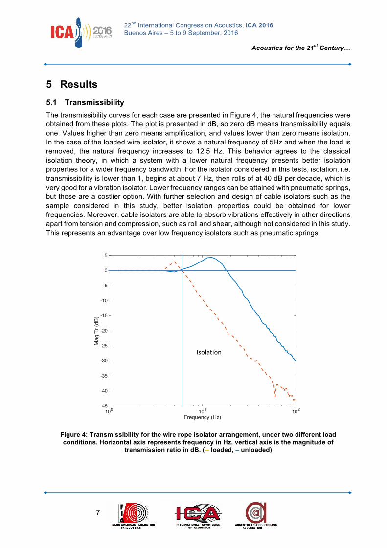
5 Results 5.1 Transmissibility The transmissibility curves for each case are presented in Figure 4, the natural frequencies were obtained from these plots. The plot is presented in dB, so zero dB means transmissibility equals one. Values higher than zero means amplification, and values lower than zero means isolation. In the case of the loaded wire isolator, it shows a natural frequency of 5Hz and when the load is removed, the natural frequency increases to 12.5 Hz. This behavior agrees to the classical isolation theory, in which a system with a lower natural frequency presents better isolation properties for a wider frequency bandwidth. For the isolator considered in this tests, isolation, i.e. transmissibility is lower than 1, begins at about 7 Hz, then rolls of at 40 dB per decade, which is very good for a vibration isolator. Lower frequency ranges can be attained with pneumatic springs, but those are a costlier option. With further selection and design of cable isolators such as the sample considered in this study, better isolation properties could be obtained for lower frequencies. Moreover, cable isolators are able to absorb vibrations effectively in other directions apart from tension and compression, such as roll and shear, although not considered in this study. This represents an advantage over low frequency isolators such as pneumatic springs.
Figure 4: Transmissibility for the wire rope isolator arrangement, under two different load conditions. Horizontal axis represents frequency in Hz, vertical axis is the magnitude of
transmission ratio in dB. (-- loaded, – unloaded)
Frequency (Hz)100 101 102
Mag
Tr (
dB)
-45
-40
-35
-30
-25
-20
-15
-10
-5
0
5
Isolation
22nd International Congress on Acoustics, ICA 2016 Buenos Aires – 5 to 9 September, 2016
Acoustics for the 21st Century…
8
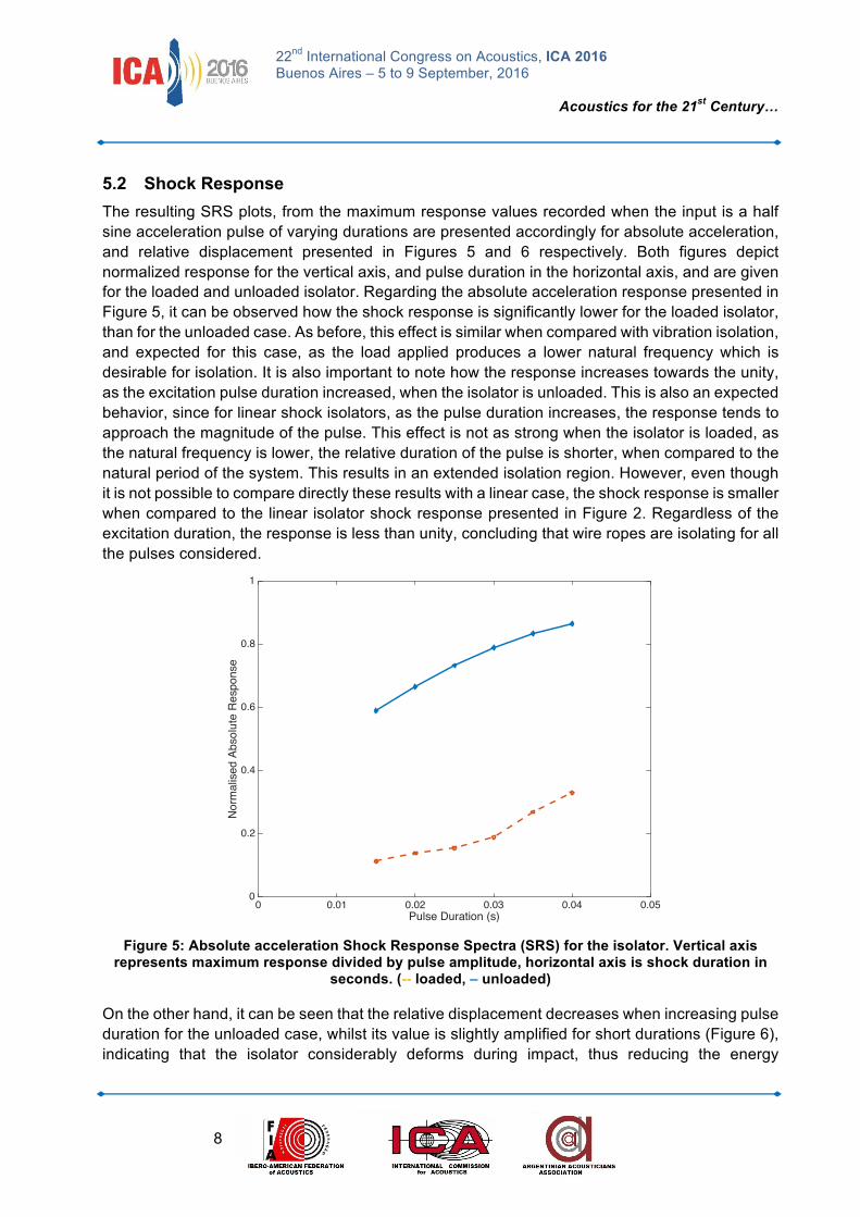
5.2 Shock Response The resulting SRS plots, from the maximum response values recorded when the input is a half sine acceleration pulse of varying durations are presented accordingly for absolute acceleration, and relative displacement presented in Figures 5 and 6 respectively. Both figures depict normalized response for the vertical axis, and pulse duration in the horizontal axis, and are given for the loaded and unloaded isolator. Regarding the absolute acceleration response presented in Figure 5, it can be observed how the shock response is significantly lower for the loaded isolator, than for the unloaded case. As before, this effect is similar when compared with vibration isolation, and expected for this case, as the load applied produces a lower natural frequency which is desirable for isolation. It is also important to note how the response increases towards the unity, as the excitation pulse duration increased, when the isolator is unloaded. This is also an expected behavior, since for linear shock isolators, as the pulse duration increases, the response tends to approach the magnitude of the pulse. This effect is not as strong when the isolator is loaded, as the natural frequency is lower, the relative duration of the pulse is shorter, when compared to the natural period of the system. This results in an extended isolation region. However, even though it is not possible to compare directly these results with a linear case, the shock response is smaller when compared to the linear isolator shock response presented in Figure 2. Regardless of the excitation duration, the response is less than unity, concluding that wire ropes are isolating for all the pulses considered.
Figure 5: Absolute acceleration Shock Response Spectra (SRS) for the isolator. Vertical axis
represents maximum response divided by pulse amplitude, horizontal axis is shock duration in seconds. (-- loaded, – unloaded)
On the other hand, it can be seen that the relative displacement decreases when increasing pulse duration for the unloaded case, whilst its value is slightly amplified for short durations (Figure 6), indicating that the isolator considerably deforms during impact, thus reducing the energy
Pulse Duration (s)0 0.01 0.02 0.03 0.04 0.05
Nor
mal
ised
Abs
olut
e R
espo
nse
0
0.2
0.4
0.6
0.8
1
22nd International Congress on Acoustics, ICA 2016 Buenos Aires – 5 to 9 September, 2016
Acoustics for the 21st Century…
9
transmission. This is a common phenomenon observed in shock isolation, as the absolute response is smaller for shorter inputs, the relative motion increases to allow for deformation and energy absorption, thus there is always a compromise between isolation and relative motion, normally associated with space i.e. clearance. As the response of absolute acceleration increases for longer inputs, relative motion tends to be smaller, i.e. there is no deformation in the isolator. This effect can be observed for the unloaded isolator. However, the loaded isolator presents a similar relative response for all the pulses considered, due to the improved isolation for absolute response explained in Figure 5, for all the pulse durations considered. Then, isolation is obtained by deformation in the isolator, or relative motion.
Figure 6: Relative displacement Shock Response Spectra (SRS) for the isolator. Vertical axis
represents maximum response divided by pulse amplitude, horizontal axis is shock duration in seconds. (-- loaded, – unloaded)
6 Conclusions An insight of the constructions and characteristics of the wire ropes was presented, as well as a brief literature review of the applications and studies related to these isolators. Transient vibration and shock isolation were briefly introduced, where the shock response spectra are used to asses shock isolation. The selection of the wire rope isolator, and the experiments developed during this study were explained with the objective to get the shock response and vibration isolation of the wire rope isolator and compared with and without a defined optimal load. Firstly, a transmissibility experiment was performed resulting in a lower natural frequency on the loaded model, showing that effective isolation begins at a low frequency, which is good compared with other isolators. Then shock responses spectra were obtained, revealing that the normalized response was always lower in the loaded case, as the effective natural frequency of the isolator is lower, and no noticeable isolation when the pulse duration was increased for the unloaded case. Finally, when
Pulse Duration (s)0 0.01 0.02 0.03 0.04 0.05
Nor
mal
ised
Rel
ativ
e R
espo
nse
0
0.2
0.4
0.6
0.8
1
1.2
1.4
1.6
1.8
2
22nd International Congress on Acoustics, ICA 2016 Buenos Aires – 5 to 9 September, 2016
Acoustics for the 21st Century…
10
considering relative displacement for the shock response, the response is very similar to the pulse amplitude for short duration pulses, so the wire rope isolator considerably deforms during impact, thus reducing the energy transmission. As a result, it was demonstrated how cable isolators present excellent shock isolation capabilities, but more research is suggested in order to test different isolator models in other situations, in order to develop a mathematical model that allows to predict the response.
References [1] Mercer, C.A. and Rees, P.L. An optimum shock isolator. Journal of Sound and Vibration. (Number 18).
Vol. 4. Pages 511-520. (1971).
[2] Snowdon, J.C. Response of nonlinear shock mountings to transient foundation displacement. The Journal of the Acoustical Society of America. Vol. 33. (Number 10). Pages 1295-1304. (1961).
[3] Molyneux, W.G. Supports for vibration isolation. Royal Aircraft Establishment. Technical Note No. Structures 211. Aeronautical Research Council, London. (1956).
[4] Eshleman, R. and Rao, P. Response of mechanical shock isolation elements to high rate input loading. Shock and Vibration Bulletin. Shock and Vibration Information Center. Vol. 40 (Number 5). (1969).
[5] Eshleman, R. Dynamic Response of a ring spring. The Shock and Vibration Bulletin. Part 4: Isolation, Damping, Prediction Experimental Techniques. Naval Research Laboratory. Washington D.C. (1972).
[6] Cutchins, M.A., Cochran, J.E., Kumar, J.R., Fitz-coy, N.G., Thinker, M.L. Initial Investigations into the damping characteristics of wire rope vibration isolators. Auburn University, Aerospace Engineering, Technical Report. 87-91. (1987).
[7] Cutchins, M.A., Tinker, M.L. Damping Phenomena in a wire rope vibration isolation system. Journal of Sound and Vibration. Vol. 157. (Number 1). Pages 7-18. (1992).
[8] Demetriades, G.F., Constantinou, M.C., Reinhorn, A.M. Study of wire rope systems for seismic protection of equipment in buildings. Engineer Structures. Vol. 15 (Number 5). Pages 321-334. (1993).
[9] Popp, K. Non-smooth Mechanical Systems. Journal of Applied Mathematics and Mechanics. Vol. 64 (Number 5), pages 765-772. (2000).
[10] Georges, R., Vickery, J. Design of tuned mass dampers incorporating wire rope springs. Journal of Wind Engineering and Industrial Aerodynamics. No. 91. Pages 1363-1385. (2003).
[11] Wang, L., Yang, L., Haung, D. An impact dynamics analysis on a new crashworthy device against ship–bridge collision. International Journal of Impact Engineering. No. 35. Pages 895-904. (2008).
[12] Hogea, D., Bausic, F. Vertical static tests of the wire rope isolators. Technical University of Civil Engineering of Bucharest, Romania. (2005).
[13] Foss G.C. Modal Damping Estimates from Static Load-Deflection Curves. Structural Dynamics Laboratory, Boeing Commercial Airplane Group, Box 3707, MC 1W-06, Seattle, WA 98124. (2005).
[14] Harris C.M. and Crede C.E. Shock and Vibration Handbook. New York. McGraw-Hill. (1996).
[15] Ledezma-Ramirez D.F. and Tapia-Gonzalez P.E. Experimental characterisation of dry friction isolators for shock vibration isolation. Proceedings of the 22nd International Congress on Sound and Vibration. ISSN 2329-3675. ISBN 978-88-88942-48-3. T09.SS03. http://iiav.org/archives_icsv_last/2015_icsv22/content/papers/papers/full_paper_30_20150314004732538.pdf