Experimental facility for development of high-temperature reactortechnology: instrumentation needs and challengesPiyush Sabharwall1*, James E. O’Brien1, SuJong Yoon1, and Xiaodong Sun2
1 Idaho National Laboratory, PO Box 1625, Idaho Falls, ID 83415-3860, USA2 Mechanical and Aerospace Engineering, Ohio State University, Columbus, Ohio, USA
* e-mail: P
This is an O
Received: 1 May 2015 / Received in final form: 8 October 2015 / Accepted: 2 November 2015Published online: 11 December 2015
Abstract. A high-temperature, multi-fluid, multi-loop test facility is under development at the Idaho NationalLaboratory for support of thermal hydraulic materials, and system integration research for high-temperaturereactors. The experimental facility includes a high-temperature helium loop, a liquid salt loop, and a hot water/steam loop. The three loops will be thermally coupled through an intermediate heat exchanger (IHX) and asecondary heat exchanger (SHX). Research topics to be addressed include the characterization and performanceevaluation of candidate compact heat exchangers such as printed circuit heat exchangers (PCHEs) atprototypical operating conditions. Each loop will also include an interchangeable high-temperature test sectionthat can be customized to address specific research issues associated with each working fluid. This paper alsodiscusses needs and challenges associated with advanced instrumentation for the multi-loop facility, which couldbe further applied to advanced high-temperature reactors. Based on its relevance to advanced reactor systems,the new facility has been named the Advanced Reactor Technology Integral System Test (ARTIST) facility. Apreliminary design configuration of the ARTIST facility will be presented with the required design and operatingcharacteristics of the various components. The initial configuration will include a high-temperature (750 °C),high-pressure (7MPa) helium loop thermally integrated with a molten fluoride salt (KF-ZrF4) flow loopoperating at low pressure (0.2MPa), at a temperature of ∼450 °C. The salt loop will be thermally integrated withthe steam/water loop operating at PWR conditions. Experiment design challenges include identifying suitablematerials and components that will withstand the required loop operating conditions. The instrumentation needsto be highly accurate (negligible drift) in measuring operational data for extended periods of times, as datacollected will be used for code and model verification and validation, one of the key purposes for the loop. Theexperimental facility will provide a much-needed database for successful development of advanced reactors andprovide insight into the needs and challenges in instrumentation for advanced high-temperature reactors.
1 Introduction
Effective and robust high-temperature heat transfersystems are fundamental to successful deployment ofAdvanced High Temperature Reactor (AHTR) systemsfor both power generation and non-electric applications. Ahighly versatile test facility is needed to address researchand development (R&D) and component qualificationneeds. Key activities of this test facility would include (1)qualification and testing of critical components in a high-temperature, high-pressure environment, (2) materialsdevelopment and qualification, and (3) manufacturer andsupplier evaluation and development. A small-scale testloop could provide for early testing of components and
pen Access article distributed under the terms of the Creative Comwhich permits unrestricted use, distribution, and reproduction
design options that require special development tests beforefinalizing the design of AHTR components and qualifyingthem for operation in the larger loop or demonstrationfacility. Since a suitable facility does not exist for testingadvanced reactor heat transfer system components (e.g.,intermediate heat exchanger [IHX], valves, etc.), reactorinternals, or the interface with the heat application plant, alaboratory-directed research and development project wasapproved to initiate development of such a facility at IdahoNational Laboratory. This facility will include threethermally coupled flow loops: a high-temperature He loop,a liquid salt intermediate loop, and a high-pressure waterloop. Based on its relevance to advanced reactor systems,the new facility has been named the Advanced ReactorTechnology Integral System Test (ARTIST) facility.
AHTR plant designs often include an intermediate heattransfer loop (IHTL) with heat exchangers at either end to
mons Attribution License (http://creativecommons.org/licenses/by/4.0),in any medium, provided the original work is properly cited.
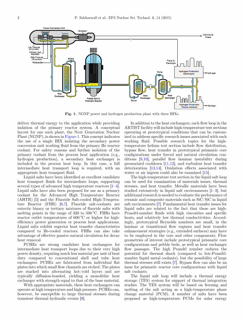
Fig. 1. NGNP power and hydrogen production plant with three IHXs.
2 P. Sabharwall et al.: EPJ Nuclear Sci. Technol. 1, 14 (2015)
deliver thermal energy to the application while providingisolation of the primary reactor system. A conceptuallayout for one such plant, the Next Generation NuclearPlant (NGNP), is shown in Figure 1. This concept indicatesthe use of a single IHX isolating the secondary powerconversion unit working fluid from the primary He reactorcoolant. For safety reasons and further isolation of theprimary coolant from the process heat application (e.g.,hydrogen production), a secondary heat exchanger isincluded in the process heat loop. In this case, a fullintermediate heat transport loop is required, with anappropriate heat transport fluid.
Liquid salts have been identified as excellent candidateheat transport fluids for intermediate loops, supportingseveral types of advanced high temperature reactors [1–4].Liquid salts have also been proposed for use as a primarycoolant for the Advanced High Temperature Reactor(AHTR) [5] and the Fluoride Salt-cooled High-Tempera-ture Reactor (FHR) [6,7]. Fluoride salt-coolants areeutectic binary or tertiary mixtures of fluoride salts withmelting points in the range of 320 to 500 °C. FHRs havereactor outlet temperatures of 600 °C or higher for high-efficiency power generation or process heat applications.Liquid salts exhibit superior heat transfer characteristicscompared to He-cooled reactors. FHRs can also takeadvantage of effective passive natural circulation for decayheat removal.
PCHEs are strong candidate heat exchangers forintermediate heat transport loops due to their very highpower density, requiring much less material per unit of heatduty compared to conventional shell and tube heatexchangers. PCHEs are fabricated from individual flatplates into which small flow channels are etched. The platesare stacked into alternating hot/cold layers and aretypically diffusion-bonded, yielding a monolithic heatexchanger with strength equal to that of the base material.
With appropriate materials, these heat exchangers canoperate at high temperature and high pressure. PCHEs can,however, be susceptible to large thermal stresses duringtransient thermal hydraulic events [8].
In addition to the heat exchangers, each flow loop in theARTIST facility will include high-temperature test sectionsoperating at prototypical conditions that can be custom-ized to address specific research issues associated with eachworking fluid. Possible research topics for the high-temperature helium test section include flow distribution,bypass flow, heat transfer in prototypical prismatic coreconfigurations under forced and natural circulation con-ditions [9,10], parallel flow laminar instability duringpressurized cooldown [11,12], and turbulent heat transferdeterioration [13,14]. Oxidation effects associated withwater or air ingress could also be examined [15].
The high-temperature test section in the liquid salt loopcan be used for examination of materials issues, thermalstresses, and heat transfer. Metallic materials have beenstudied extensively in liquid salt environments [1–3], butadditional research is needed to evaluate the performance ofceramic and composite materials such as SiC/SiC in liquidsalt environments [7]. Fundamental heat transfer issues forliquid salts are related to the fact that these are high-Prandtl-number fluids with high viscosities and specificheats, and relatively low thermal conductivities. Accord-ingly, prototypical Reynolds numbers are small, in thelaminar or transitional flow regimes and heat transferenhancement strategies (e.g., extended surfaces) may haveto be employed in the core and other components. Flowgeometries of interest include prototypical prismatic coreconfigurations and pebble beds, as well as heat exchangerflow passages. The high Prandtl number reduces thepotential for thermal shock (compared to low-Prandtl-number liquid metal coolants), but the possibility of largethermal stresses still exists [7]. Bypass flow can also be anissue for prismatic reactor core configurations with liquidsalt coolants.
The liquid salt loop will include a thermal energystorage (TES) system for support of thermal integrationstudies. The TES system will be based on freezing andmelting of the salt acting as a high-temperature phasechange material (PCM). A number of salts have beenproposed as high-temperature PCMs for solar energy
P. Sabharwall et al.: EPJ Nuclear Sci. Technol. 1, 14 (2015) 3
applications [16,17]. The advantage of using a PCM is thatthermal energy can be supplied to the process at a nearlyconstant temperature, taking advantage of the latent heatof melting.
The high-temperature test section in the steam/waterloop will be used primarily for prototypic evaluation of newcladding materials and accident-tolerant fuels. It will bedesigned to characterize the thermal, chemical, andstructural properties of candidate advanced fuel claddingmaterials and designs under various simulated flow andinternal heating conditions to mimic operational reactorconditions prior to in-reactor testing. The capability forout-of-pile mock-up testing of candidate (surrogate) fuel-clad systems is essential for reactor readiness, in particularwhen innovative fuel cladding will be in direct contact withthe test reactor primary coolant system without secondarycontainment. Careful control of water chemistry will beessential for these studies; a water chemistry control sectionis included in the design of the loop.
Flow-induced vibration of fuel rod bundles has beenidentified as an important issue for sodium-cooled reactors[18]. The high-temperature test section of the hot water loopcan also potentially be used to study flow-induced vibrationof simulated sodium-cooled reactor fuel rod bundles. Hotwater at 200 °Cand1.38MPamatches thedensity of sodium.This condition is well within the operational range of theproposed loop.
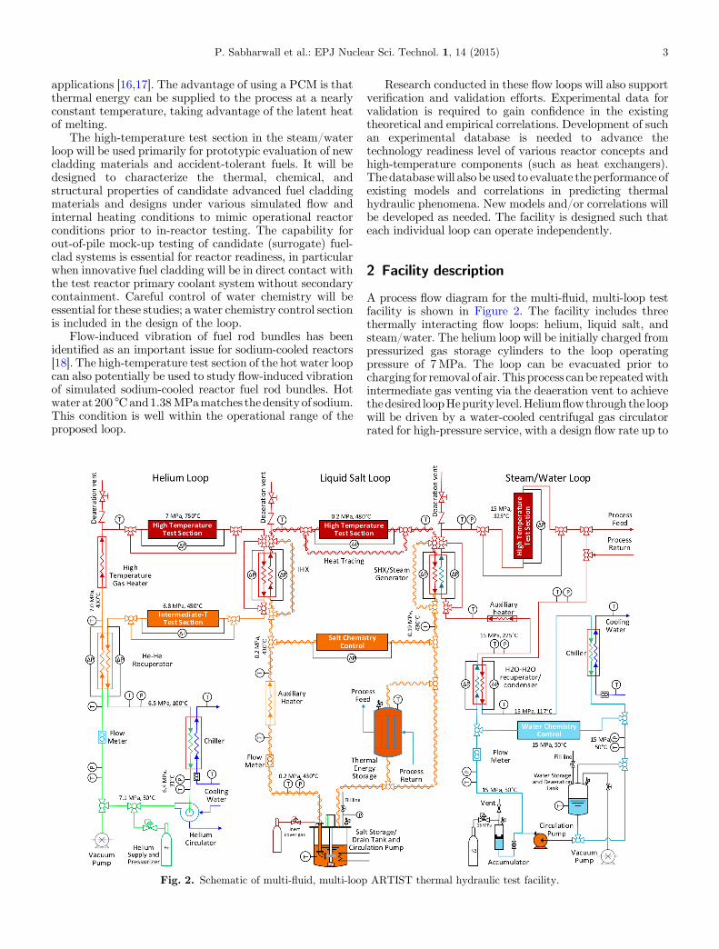
Fig. 2. Schematic of multi-fluid, multi-loop
Research conducted in these flow loops will also supportverification and validation efforts. Experimental data forvalidation is required to gain confidence in the existingtheoretical and empirical correlations. Development of suchan experimental database is needed to advance thetechnology readiness level of various reactor concepts andhigh-temperature components (such as heat exchangers).Thedatabasewill also be used to evaluate theperformance ofexisting models and correlations in predicting thermalhydraulic phenomena. New models and/or correlations willbe developed as needed. The facility is designed such thateach individual loop can operate independently.
2 Facility description
A process flow diagram for the multi-fluid, multi-loop testfacility is shown in Figure 2. The facility includes threethermally interacting flow loops: helium, liquid salt, andsteam/water. The helium loop will be initially charged frompressurized gas storage cylinders to the loop operatingpressure of 7MPa. The loop can be evacuated prior tocharging for removal of air. This process canbe repeatedwithintermediate gas venting via the deaeration vent to achievethedesired loopHepurity level.Heliumflowthrough the loopwill be driven by a water-cooled centrifugal gas circulatorrated for high-pressure service, with a design flow rate up to
ARTIST thermal hydraulic test facility.
4 P. Sabharwall et al.: EPJ Nuclear Sci. Technol. 1, 14 (2015)
525 LPM at 7MPa (11,300 SLPM) and a loop pressure dropof 100 kPa. The circulator flow rate will be controlled bymeans of a variable-frequency drive coupled to the motor.The helium circulator will be designed to operate with amaximum helium temperature of 100 °C. It is thereforelocated in the low-temperature section of the helium flowloop. The gas is preheated to intermediate temperature byflowing through a helium-to-helium recuperator (60 kWduty) that transfers heat from the intermediate-temperaturehelium return flow to the low-temperature stream.The high-temperature portion of the flow loop is designed to handlehelium temperatures up to 800 °C. This temperature will beachieved using a high-temperature in-line electrical gasheater located downstream of the recuperator. The nominalpower requirement for the high-temperature gas heater is60 kW.
The helium loop will include a high-temperature testsection for heat transfer andmaterials studies. Downstreamof the test section, the helium gas flows through a heatexchanger where heat will be transferred to the adjacentliquid salt loop using a scaled version of an IHX. Thebaseline design for this heat exchanger will be a high-efficiency compact microchannel PCHE with a nominalheat duty of 55 kW. Analysis of a PCHE operating with Heas the hot fluid and liquid salt as the cold fluid is provided inreference [8]. Downstream of the IHX, the helium flowsthrough an intermediate-temperature test section and therecuperator to transfer heat back to the inlet stream.Downstream of the recuperator, the helium flows through awater-cooled chiller (10 kW) to cool it down to the gascirculator operating temperature. The baseline design forthe He-He recuperator will also be a PCHE. In addition toits heat recuperation role, this heat exchanger simulates anIHX for the case in which He is used as an intermediate heattransfer fluid, albeit at lower operating temperatures.Performance data obtained from this recuperator willprovide useful validation data for the reactor systemapplication. The He-He version of the IHX operates withessentially balanced high pressure on both sides, minimiz-ing the possibility of leakage of primary fluid to thesecondary side.
The center part of Figure 2 shows the liquid salt portionof the multi-loop facility. The loop will be charged with saltfrom the salt storage tank. This tank will include a heaterdesigned to heat the frozen salt to a temperature above itsmelting point. The head space in the salt storage tank willbe maintained at slightly elevated pressure with an inertcover gas. The inert gas will prevent in-leakage of air ormoisture, minimizing the potential for salt contamination.During startup, liquid salt will drain to the pump inlet bygravity, with assist from the cover gas pressure, as needed.The salt pump will be designed to operate at 450 °C at lowpressure (∼0.2MPa). It will provide salt flow rates up to20 LPM. A standard stainless steel such as SS316 may besuitable for the pump material, but other alloys will also beconsidered. The entire liquid salt flow loop will be heat-traced to prevent salt from freezing and causing a flowblockage. Downstream of the pump, the salt flow rate willbe measured using a high-temperature ultrasonic flowtransducer. The salt temperature will be boosted as neededto the desired intermediate temperature using an in-line
electrical auxiliary heater. Careful control of salt chemistrywill be critical for successful operation of this loop; a saltchemistry control section will be installed at the intermedi-ate temperature location. The salt temperature willincrease to ∼480 °C as it flows through the IHX and heatis transferred from the helium loop to the salt loop. Notethat the He-salt IHX will have high-pressure helium on oneside and low-pressure salt on the other, establishing thepotential for high-temperature creep and leakage ofprimary He into the salt loop, emphasizing the need fordemonstrating complete IHX integrity at prototypicalconditions.
For independent operation of the liquid salt loop, theIHX will not be required. An IHX bypass will enable saltflow directly to the high-temperature test section withoutthe pressure drop associated with the IHX. The auxiliaryheater will be designed to independently heat the salt to themaximum operating temperature of 480 °C even when theIHX is bypassed. Its nominal design heater power will be75 kW. Downstream of the high-temperature test section,the liquid salt flows through the SHX, transferring heat tothe tertiary steam/water loop. A bypass line around theSHX is also provided for cases in which the salt loop will beoperated independently of the steam/water loop. The saltcan then flow directly back to the pump or it can flowthrough a thermal energy storage (TES) system for processintegration studies.
The right-hand side of Figure 2 shows the steam/watertertiary loop. The SHX can serve as a steam generator orsimply a single-phase heat exchanger, depending onconditions to be simulated in the tertiary loop. For mosttests, conditions in the tertiary loop will be intended tosimulate conditions in the primary loop of a pressurizedwater reactor (PWR). PWR conditions will be needed formaterials/corrosion studies of accident-tolerant fuels, newcladding materials, crud formation, etc. Alternately, atlower operating pressure the tertiary loop can simulate thesecondary side of a PWR system, with steam generation forprocess integration studies. Flow through the hot waterloop will be produced by a pump designed to operate at15MPa with a nominal water flow rate of 5.7 LPM at15MPa and 40 °C.
Downstream of the pump, the water flows through arecuperator designed to recover heat from the high-temperature portion of the loop. The baseline recuperatorinlet and outlet water temperatures will be 50 °C and275 °C, respectively. The water is heated further to 325 °Cby heat transfer in the SHX. For cases in which the SHX isnot present or is bypassed, an auxiliary heater will be usedto achieve the desired 325 °C test section inlet temperature.Note that the SHX will also operate with a large pressuredifferential between the water side (15MPa) and the saltside (0.2MPa), establishing the potential for water leakageinto the salt, and emphasizing the need to demonstrate fullSHX integrity at these conditions. High-temperature creepshould not be a concern at these temperatures. However, at15MPa, the maximum water temperature (325 °C) is wellbelow the saturation temperature, so the water remains inthe liquid phase throughout the system for the baselinecase. The high-temperature test section in the water loopwill have a vertical orientation to support boiling (at
P. Sabharwall et al.: EPJ Nuclear Sci. Technol. 1, 14 (2015) 5
pressures lower than 15MPa) and/or natural circulationstudies. Simulated PWR core geometries in the test sectionwill support research on new cladding materials, accident-tolerant fuels, etc. Hot water or steam can be supplied toother co-located processes or experiments via the processfeed and process return lines. After flowing through thereturn side of the recuperator, the water temperature isdecreased to 117 °C. It is further reduced to the pumpoperating temperature of 50 °C by means of a water-cooledchiller. Pressure in the hot water loop will be maintained bymeans of a piston accumulator with regulated nitrogen onthe gas side. The water storage and deaeration tank will beplumbed to a vacuum pump to allow for air removal. Thewater can also be directed to flow through a chemistrycontrol section. This part of the loop will be designed toestablish the loop water chemistry. Most often, PWRwaterchemistry will be established. The chemistry control sectionwill include filtering, a water softener, and a reverse osmosisconditioner for deionization/demineralization. It will alsoprovide the ability to establish the correct pH value toensure prototypical PWR conditions.
A three-dimensional (3D) computer-aided design(CAD) model of the ARTIST experimental test facility
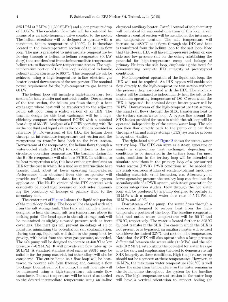
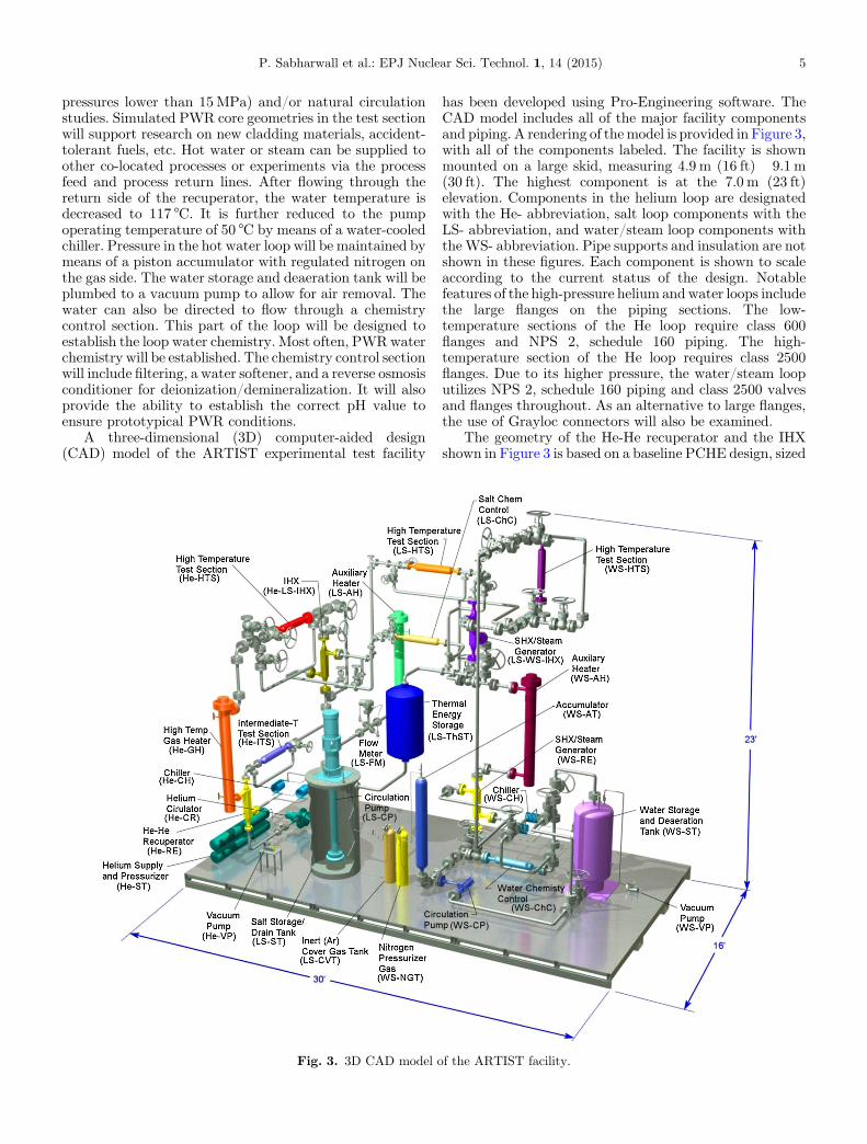
Fig. 3. 3D CAD model o
has been developed using Pro-Engineering software. TheCAD model includes all of the major facility componentsand piping. A rendering of themodel is provided in Figure 3,with all of the components labeled. The facility is shownmounted on a large skid, measuring 4.9 m (16 ft)� 9.1 m(30 ft). The highest component is at the 7.0 m (23 ft)elevation. Components in the helium loop are designatedwith the He- abbreviation, salt loop components with theLS- abbreviation, and water/steam loop components withthe WS- abbreviation. Pipe supports and insulation are notshown in these figures. Each component is shown to scaleaccording to the current status of the design. Notablefeatures of the high-pressure helium andwater loops includethe large flanges on the piping sections. The low-temperature sections of the He loop require class 600flanges and NPS 2, schedule 160 piping. The high-temperature section of the He loop requires class 2500flanges. Due to its higher pressure, the water/steam looputilizes NPS 2, schedule 160 piping and class 2500 valvesand flanges throughout. As an alternative to large flanges,the use of Grayloc connectors will also be examined.
The geometry of the He-He recuperator and the IHXshown in Figure 3 is based on a baseline PCHE design, sized
f the ARTIST facility.
6 P. Sabharwall et al.: EPJ Nuclear Sci. Technol. 1, 14 (2015)
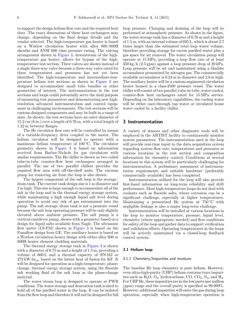
to support the design helium flow rate and the required heatduty. The exact dimensions of these heat exchangers maychange, depending on the final design details and thevendor selected. The high-temperature gas heater is basedon a Watlow circulation heater with alloy 800/800Hsheaths and ANSI 600 class pressure rating. The valvingarrangement shown in Figure 3, downstream of the high-temperature gas heater, allows for bypass of the high-temperature test section. Three valves are shown instead ofa single three-way valve because a three-way valve rated forthese temperatures and pressures has not yet beenidentified. The high-temperature and intermediate-tem-perature helium test sections as shown in Figure 3 aredesigned to accommodate small tube bundles or othergeometries of interest. The instrumentation in the testsections and loops could potentially serve the dual purposeof measuring test parameters and demonstrating new high-resolution advanced instrumentation and control equip-ment in challenging environments. The test sections will becustom-designed components and may be built in a range ofsizes. As shown, the test sections have an outer diameter of15.2 cm (6 in.) over a length of 0.76 m, with a total length of1.22 m between flanges.
The He circulator flow rate will be controlled by meansof a variable-frequency drive coupled to the motor. Thehelium circulator will be designed to operate with amaximum helium temperature of 100 °C. The circulatorgeometry shown in Figure 3 is based on informationreceived from Barber-Nichols for gas circulators withsimilar requirements. The He chiller is shown as two coiledtube-in-tube counter-flow heat exchangers arranged inparallel. The use of two parallel chillers provides therequired flow area with off-the-shelf units. The vacuumpump for removing air from the loop is also shown.
The largest component of the salt loop is the storage/drain tank. The current tank design size is 1 m diameter and2m high. This size is large enough to accommodate all of thesalt in the loop and in the thermal energy storage system,while maintaining a high enough liquid salt level duringoperation to avoid any risk of gas entrainment into thepump. The salt storage/drain tank is not a pressure vesselbecause the salt loop operating pressure will be only slightlyelevated above ambient pressure. The salt pump is avertical cantilever pump, shown with a geometry based on adesign for liquid salts available from Nagle. The ultrasonicflow meter (LS-FM) shown in Figure 3 is based on thePanaflow design from GE. The auxiliary heater is based ona Watlow circulation heater design with either alloy 600 or800H heater element cladding materials.
The thermal energy storage tank in Figure 3 is shownwith a diameter of 0.75 m and a height of 1.5 m, providing avolume of 660 L and a thermal capacity of 978MJ or272 kW-hrth, based on the latent heat of fusion for KF. Itwill be designed for operation as a high-temperature, phase-change, thermal energy storage system, using the fluoridesalt working fluid of the salt loop as the phase-changematerial.
The water/steam loop is designed to operate at PWRconditions. The water storage and deaeration tank is sized tohold all of the purified water in the loop. It can be isolatedfrom theflow loop and therefore itwill not be designed for full
loop pressure. Charging and draining of the loop will beperformed at atmospheric pressure. As shown in the figure,the water storage tank has a diameter of 0.76m and a heightof 1.5m, with an internal volume of 695 L, which is about 2.7times larger than the estimated total loop water volume,therefore providing storage for excess purified water plus agas space for air removal. The water circulation pump willoperate at 15MPa, providing a loop flow rate of at least350 kg/h (2.5 gpm) against a loop pressure drop of 20 kPa.Loop pressure will be set and maintained using a bladderaccumulator pressurized by nitrogen gas. The commerciallyavailable accumulator is 0.24m in diameter and 2.0m high.The auxiliary heater will be a custom-engineered circulationheater housed in a class-2500 pressure vessel. The waterchillerwill consist of twoparallel, tube-in-tube,water-cooled,counter-flow heat exchangers rated for 15MPa service.Depending on the laboratory capabilities, the cooling waterwill be either once-through tap water or circulated housewater cooled by a facility chiller.
3 Instrumentation
A variety of sensors and other diagnostic tools will beemployed in the ARTIST facility to continuously monitorsystem parameters. The instrumentation used in the loopwill provide real-time input to the data acquisition systemregarding system flow rate, temperatures and pressures atvarious locations in the test section and compositioninformation for chemistry control. Conditions at severallocations in this system will be particularly challenging forinstrumentation. A preliminary assessment of instrumen-tation requirements and suitable hardware (preferablycommercially available) has been completed.
Instrumentation utilized for the loop will also providefirst-hand information on long-term reliability and driftperformance. Most high-temperature loops do not deal withcoolants such as fluoride salts, where corrosion can be asignificant challenge, especially at higher temperatures.Maintaining a pressurized He system at 750 °C withnegligible leakage is also a major long-term challenge.
Instrumentation will be installed at various locations inthe loop to monitor temperature, pressure, liquid level,chemistry (where appropriate/needed) and flow conditionsfor safety of the loop and gather data to support verificationand validation efforts. Operating temperatures in the loopswill be actively maintained via a closed-loop feedbackcontrol system.
3.1 Helium loop
3.1.1 Chemistry/Impurities and moisture
The baseline He loop chemistry is pure helium. However,even ultra-high-purity (UHP) helium contains trace impuri-ties such as H2O, O2, hydrocarbons, CO, CO2, N2, and H2.ForUHPHe, these impurities are in the lowparts-per-million(ppm) range and the overall purity is specified as 99.999%.However, additional impurities will enter the gas during loopoperation, especially when high-temperature operation is
P. Sabharwall et al.: EPJ Nuclear Sci. Technol. 1, 14 (2015) 7
initiated. Furthermore, some gases may have to beintentionally included as additives. For example, low levelsof oxygen may be needed to maintain protective oxide scaleon metallic components [1]. On the other hand, oxygen cancorrode graphite in the vessel core, which can in turn releaseadditional gases such as CO and CO2. These gases cansubsequently form deposits on metallic components. Carefulmonitoring and control of these gases will be critical forsuccessful long-term operation of the He loop. Monitoring isusually performed by withdrawing a gas sample from thelow-temperature part of the loop for analysis using a gaschromatograph (GC) system.
3.1.2 Flow rate
Flow rate in the He loop will be measured in the low-temperature (∼50 °C) leg of the loop just downstream of thecirculator. There are several options for measuring heliumflow rate including thermal mass flow meter, coriolis meter,venturi meter, or vortex flow meter. For this closed-loophigh-flow-rate helium flow system, one of the major costswill be the circulator and its cost will increase with looppressure drop. Therefore, a low-pressure-drop flow mea-surement device is desired. The permanent pressure loss forvortex flow meters is quite low, and they provide excellentaccuracy with pressure and temperature compensation toyield a true mass flow measurement. Commercial units thatmeet the pressure and temperature specifications for thehelium flow loop are available from several vendors.Thermal mass flow meters with laminar flow elements willalso be considered if the pressure drop is low enough.
3.1.3 Pressure: absolute and differential
Pressure instrumentation for the helium loop will includeseveral absolute pressure transducers, as indicated inFigure 2, plus several differential pressure transducers(dP cells). The differential transducers will be usedprimarily to measure pressure drop across the IHX andthe recuperator. In some cases, differential pressure may beneeded across the high-temperature test section as well.The differential transducers will be designed to measurerelatively small pressure differences while operating at highabsolute pressure. Each differential transducer assemblywill include a dP cell manifold that allows zeroing of the cellat high absolute pressure.
3.1.4 Temperature
Temperature measurements for the helium loop will mostlybe acquired using type K, stainless-steel or inconel-sheathedungrounded 1/8- or 1/16-in. thermocouples inserted intothe flow stream using compression fittings. Inconelsheathing will be used on the high-temperature portionof the loop. Type K thermocouples are rated for service upto 1260 °C. The high-temperature gas heater will befeedback-controlled using the temperature just down-stream of the heater as the process variable.
3.2 Salt loop
Instrumentation specification for the salt loop will adapt tolessons learned from researchers at the University ofWisconsin, The Ohio State University, and Oak RidgeNational Laboratory, based on their recent experiences insalt loop development.
3.2.1 Chemistry control
Pretreatment of fluoride salts is necessary before introduc-ing them to the flow loop, to remove oxygen, moisture, andother contaminants from the mixture. In addition,continuous monitoring and chemistry control will benecessary to monitor and remove any contaminants suchas metal oxides that build up in the mixture as a result ofinteraction with loop materials or due to air or moistureingress. Monitoring may include the use of a hightemperature electrochemical oxygen sensor based onyttria-stabilized zirconia (YSZ) or yttria-doped thoria(YDT) [19]. Development of a continuous chemistrymonitoring system for the salt loop will be an importantaspect of the loop design process.
3.2.2 Flow rate
Most standard flow measurements include some kind ofprobe or sensor in direct contact with the fluid. Many ofthese are not appropriate for the liquid salt application. Themeasurement environment is very challenging both interms of temperature and materials compatibility. Ultra-sonic flow meters can be used for this application.Nonintrusive clamp-on ultrasonic flow meters are attachedto the outside of a section of pipe with no fluid contact.These are available from several vendors.Wetted ultrasonicflowmeters are permanently mounted on a spool piece; theyprovide higher accuracy [20], but appropriate materialsmust be selected for the pipe body and the sensor heads.
3.2.3 Pressure and delta-P
A particularly important measurement for this loop will bethe pressure drop across the IHX and the SHX. Pressuremeasurements will be challenging in the salt loop. Theminimum requirement is that the transducer can operate attemperatures above the melting point of the salt. Meltpressure transducers operate by hydraulic transmission ofpressure through a low-vapor-pressure incompressibleliquid from a wetted diaphragm to a measurementdiaphragm located away from the high temperature fluid[21]. NaK is commonly used as a hydraulic transmissionfluid for high-temperature melt pressure transducers. It hasa freezing point that is well below room temperature(∼–12.8 °C) and a boiling point of 785 °C. NaK-filled meltpressure transducers operate over a temperature range up to538 °C,which is an excellentmatch for the salt loop operatingtemperature range. Unfortunately, these transducers aregenerally only commercially available for high pressure
8 P. Sabharwall et al.: EPJ Nuclear Sci. Technol. 1, 14 (2015)
ranges (lowest range is typically 0–10MPa), whereas the saltloop will operate at low pressure (∼0.2MPa). The moltensalt loop at ORNL uses a NaK-buffered pressure transducerthat prevents overheating of the transducer electronics [22].A direct diaphragm displacement pressure measurementprobe has also been researched at ORNL and U. of TN for amolten salt loop application [23]. This probe incorporated anickel diaphragm for a direct capacitance sensor-basedmeasurement. Specification and selection of absolute anddifferential pressure transducers for the molten salt loop willbe a design challenge to be addressed during the detaileddesign phase.
3.2.4 Temperature
For the liquid salt loop, type K inconel-sheathedungrounded 1/8- or 1/16-in. thermocouples inserted intothe flow stream using compression fittings will be used formost loop temperature measurements. Surface-mountedthermocouples will also be used to provide the processvariable measurements required for feedback control of theheat-traced sections of piping and vessel walls in the saltloop.
3.2.5 Liquid level
Liquid level in the salt storage tank will change duringsystem startup and shutdown. Liquid level in the saltstorage tank will be obtained using non-contact high-temperature ultrasonic or microwave level transmitters.
3.3 Water/Steam loop
3.3.1 Chemistry control
The water flow loop includes a chemistry control section.Water chemistry control is critical for proper simulation ofPWR conditions. Control of water chemistry parameters inan operating PWR is aimed at striking a balance betweenassuring the integrity of the primary system pressureboundary, the integrity of the fuel cladding, and tominimize out-of-core radiation fields [24]. For example,elevated pH can reduce out-of-core radiation fields, but canalso lead to elevated lithium levels that can lead to alloy 600cracking. Low pH values can lead to increased cruddeposits. Operation at pH values of 6.9–7.4 is generallyrecommended. pH control is achieved by controlling theboric acid (H3BO3) concentration (∼500 ppm) and thelithium (LiOH) concentration (∼2.2 ppm). Corrosionexperiments with simulated PWR water chemistry gener-ally follow these guidelines [25]. In addition, minimizationof dissolved oxygen to <5 ppb is desired. Small amounts ofdissolved hydrogen can be included in PWR water tomaintain reducing conditions and to eliminate radiolyti-cally produced oxygen.
Instrumentation for the water loop will include in-linepH and dissolved oxygen sensors. Both of these sensors willbe installed in the low-temperature part of the water loop.
These sensors are available from a number of vendors withranges that are suitable for this application.
3.3.2 Flow rate
Flow rates in the water loop will be measured at full looppressure (up to 15MPa) and at low temperature (∼50 °C).The biggest challenge for this flow meter is the pressure,which is higher than the standard pressure rating on mostoff-the-shelf thermal or coriolis mass flow meters andcontrollers. GE does offer a high-pressure coriolis flowmeter(RHM015) that is suitable for pressures up to 70MPa, witha wide range of flow rates. Alternately, turbine flow metersare available from several manufacturers with standardpressure ratings of 35MPa or higher over a wide range offlow rates.
3.3.3 Pressure and delta-P
Pressure instrumentation for the water loop will includeseveral absolute pressure transducers, as indicated inFigure 2, plus several differential pressure transducers.The differential transducers will be used primarily tomeasure pressure drop across the SHX and the recuperator.In some cases, differential pressure may be needed acrossthe high temperature test section as well. The differentialtransducers will be designed to measure relatively smallpressure differences while operating at high absolutepressure. Each differential transducer assembly will includea dP cell manifold that allows zeroing of the cell at highabsolute pressure.
3.3.4 Temperature
For the water loop, type K inconel-sheathed ungrounded1/8- or 1/16-in. thermocouples inserted into the flow streamusing compression fittings will be used for most looptemperature measurements.
4 Conclusions
A conceptual design for a new high-temperature, multi-fluid, multi-loop test facility has been presented in thisstudy. This facility will support thermal hydraulicmaterials, and thermal energy storage research for nuclearand nuclear-hybrid applications. Three flow loops will beincluded: a high-temperature helium loop, a liquid salt loop,and a hot water/steam loop. The three loops will bethermally coupled through an intermediate heat exchanger(IHX) and a secondary heat exchanger (SHX). The saltloop is representative of an advanced reactor systemintermediate heat transfer loop. Advanced reactor systemsoften include an intermediate heat transfer loop (IHTL)with heat exchangers at either end to deliver thermalenergy to the application while providing isolation of theprimary reactor system. Liquid salts have been identified asexcellent candidate heat transport fluids for intermediate
P. Sabharwall et al.: EPJ Nuclear Sci. Technol. 1, 14 (2015) 9
loops, supporting several types of advanced high tempera-ture reactors. Liquid salts have also been proposed for use asa primary coolant for the Advanced High TemperatureReactor (AHTR) and the Fluoride Salt-cooled High-Temperature Reactor (FHR).
Engineering research topics to be addressed with thisfacility include the characterization and performanceevaluation of candidate compact heat exchangers such asprinted circuit heat exchangers (PCHEs) at prototypicaloperating conditions, flow and heat transfer issues relatedto core thermal hydraulics in advanced helium-cooled andsalt-cooled reactors, and evaluation of corrosion behavior ofnew cladding materials and accident-tolerant fuels forLWRs at prototypical conditions. Research performed inthis test facility will advance the state of the art andtechnology readiness level of high temperature intermedi-ate heat exchangers (IHXs) for nuclear applications whileestablishing INL as a center of excellence for thedevelopment and certification of this technology. Thethermal energy storage capability will support research anddemonstration activities related to process heat delivery fora variety of hybrid energy systems and grid stabilizationstrategies.
Fundamental research topics will also be addressed withthis facility. Each loop will include a high-temperature testsection for this purpose. Research topics that may bestudied in the high temperature helium test section includeflow distribution, bypass flow, and heat transfer inprototypical prismatic core configurations under forcedand natural circulation conditions, parallel flow laminarinstability during pressurized cooldown, and turbulent heattransfer deterioration. Oxidation effects associated withwater or air ingress could also be examined. The hightemperature test section in the liquid salt loop can be usedfor examination of materials issues, thermal stresses, andhigh-Prandtl-number heat transfer issues. The hightemperature test section in the steam/water loop will beused primarily for prototypic evaluation of new claddingmaterials and accident-tolerant fuels. It will be designed tocharacterize the thermal, chemical, and structural proper-ties of candidate advanced fuel cladding materials anddesigns under a variety of simulated flow and internalheating conditions to mimic operational reactor conditionsprior to in-reactor testing. The liquid salt loop will alsoinclude thermal energy storage (TES) system for support ofthermal integration studies. The TES system will be basedon freezing and melting of the salt acting as a high-temperature phase change material (PCM).
Conceptual design will be completed for all three loopsas proposed, but the construction of each individual loopwill depend on testing needs and future funding.
References
1. D.F. Williams, K.T. Clarno, L.M. Toth, Assessment ofcandidate liquid-salt coolants for the Advanced High-Temperature Reactor (AHTR) ORNL/TM-2006/12, OakRidge National Laboratory, Tennessee, 2006
2. D.F. Williams, K.T. Clarno, Evaluation of salt coolants forreactor applications, Nucl. Technol. 163, 330 (2008)
3. M.S. Sohal, M.A. Ebner, P. Sabharwall, P. Sharpe,Engineering database of liquid salt thermophysical andthermochemical properties, INL/EXT-10-18297, Idaho, 2010
4. O. Benes, C. Cabet, S. Delpech, P. Hosnedl, V. Ignatiev, R.Konings, D. Lecarpentier, O. Matal, E. Merle-Lucotte, C.Renault, J. Uhlir, Assessment of liquid salts for innovativeapplications, ALISIA Deliverable (D-50), European Commis-sion, Euratom Research and Training Programme on NuclearEnergy, 2009
5. C.W. Forsberg, The advanced high-temperature reactor:high-temperature fuel, liquid salt coolant, liquid-metal-reactor plant, Prog. Nucl. Energy 47, 32 (2005)
6. R.O. Scarlat, P.F. Peterson, The current status of fluoridesalt-cooled high-temperature reactor (FHR) technology andits overlap with HIF target chamber concepts, Nucl. Inst.Methods Phys. Res. A. 733, 57 (2013)
7. N.Zweibaum,G.Cao,A.T.Cisneros,B.Kelleher,M.R.Laufer,R.O. Scarlat, J.E. Seifried, M.H. Anderson, C.W. Forsberg, E.Greenspan, L.W.Hu,P.F.Peterson,K. Sridharan,Phenomenol-ogy,methods, and experimental program for fluoride-salt-cooledhigh temperature reactors, Prog. Nucl. Energy 77, 390 (2014)
8. E. Urquiza, K. Lee, P.F. Peterson, R. Grief, Multiscaletransient thermal, hydraulic, and mechanical analysismethodology of a printed circuit heat exchanger using aneffective porous media approach, J. Therm. Sci. Eng. Appl. 5,041011-1 (2013)
9. R.S. Schultz et al., Next generation nuclear plant methodstechnical program plan, INL/EXT-06-11804, Idaho, 2007
10. Y. Tung, R.W. Johnson, Y. Ferng, C. Chieng, Bypass flowcomputations on the LOFA transient in a VHTR, Appl.Therm. Eng. 62, 415 (2014)
11. E. Reshotko, Analysis of laminar instability problem in gas-cooled nuclear reactor passages, AIAA J. 5, 1606 (1967)
12. G. Melese, R. Katz, Thermal and flow design of helium-cooledreactors (ANS, Illinois, 1984)
13. D.M. McEligot, J.D. Jackson, Deterioration criteria forconvective heat transfer in gas flow through non-circularducts, Nucl. Eng. Design 232, 327 (2004)
14. J.I. Lee, P. Hehzlar, P. Saha, M.S. Kazimi, Studies of thedeteriorated turbulent heat transfer regime for the gas-cooledfast reactor decay heat removal system, Nucl. Eng. Design237, 1033 (2007)
15. D. Chapin, S. Kiffer, J. Nestell, The very high temperaturereactor: a technical summary (MPR Associates, 2004)
16. A. Hoshi, D.R. Mills, A. Bittar, T.S. Saitoh, Screening of highmelting point Phase ChangeMaterials (PCM) in solar thermalconcentration technology, Solar Energy 79, 332 (2005)
17. J.C. Gomez, High-temperature Phase Change Materials(PCM) candidates for thermal energy storage applications,NREL Report, NREL/TP-5500-51446, 2011
18. E. Bojarsky, H. Deckers, H. Lehning, P.H. Reiser, L. Schmidt,THIBO experiments – thermohydraulically induced fuel pinoscillations in Na-cooled reactors, Nucl. Eng. Design 130, 21(1991)
19. L. Meyer, Challenges related to the use of liquid metal andmolten salt coolants in advanced reactors, TECDOC-1696(IAEA, Austria, 2013)
20. GE Measurement and Control Brochure, Panaflow HTpanametrics ultrasonic SIL flow meter for liquids, 2014
21. Gefran Brochure, Melt pressure transducers and transmitters,2014
22. G.L. Yoder, A. Aaron, B. Cunningham,D. Fugate, D. Holcomb,R. Kisner, F. Peretz, K. Robb, J. Wilgen, D. Wilson, An
10 P. Sabharwall et al.: EPJ Nuclear Sci. Technol. 1, 14 (2015)
experimental test facility to support development of thefluoride-salt-cooled high-temperature reactor,Ann.Nucl. Energy64, 511(2014)
23. J.A. Ritchie, Pressure measurement instrumentation in ahigh temperature molten salt test loop, MS Thesis, U. ofTennessee, 2010
24. PWR Primary Water Chemistry Guidelines, EPRI TechnicalReport, TR-105714-V1R4, 1999
25. T. Terachi, T. Yamada, T. Miyamotot, K. Arioka, K. Fuku,Corrosion behavior of stainless steels in simulated PWRprimary water – Effect of chromium content in alloys anddissolved hydrogen, J. Nucl. Sci. Technol. 45, 975 (2008)
Cite this article as: Piyush Sabharwall, James E. O’Brien, SuJong Yoon, Xiaodong Sun, Experimental facility for development ofhigh-temperature reactor technology: instrumentation needs and challenges, EPJ Nuclear Sci. Technol. 1, 14 (2015)