Page 1
Vol-3 Issue-4 2017 IJARIIE-ISSN (O)-2395-4396
6304 www.ijariie.com 2283
Experimental investigation and FEA of wear in
gear at torque loading conditions
MUNDE RAHUL M.1, D. P. KAMBLE.
2
1PG Student, Department of Mechanical Engineering, APCOER, Parvati, Pune, Maharashtra, India 2Professor, Department of Mechanical Engineering, APCOER, Parvati, Pune, Maharashtra, India
ABSTRACT Gear is machine element, which used to transmit the power in the modern engineering era. They differ from small in
size used for the watches and the large gears used in all types of trains, bridge lifting mechanism, and industrial
application with a outspread velocity ratios. The gears are a main constituent element that provides necessary
support for mechanism in many machines like automobile sector, civil sector and various engineering application
like mills, industries, hoisting and transmitting machinery and marine engines, etc.
Gear element is used usually to transfer circular motion by variation of torque loadings. During their
process gear teeth are undergo various contact and bending stresses. Gear imparts high pressure on pinion
resulting in wear causing rough surfaces, pitting etc., this locations are prone to crack initiation causing fatigue
failure. In this project work investigation of stresses and strains will be done at a specified torque loading using
Experimental and finite element technique. Design and CAD Modeling of an existing gear pair will be done using
CATIA V5 software. Discretization (Meshing) will be done by ANSYS Package. Torque loading will be done by FEA
package ANSYS to analyze stresses. Setup is prepared to mount gears for replicating torque loadings. Gear surfaces
will be analyzed to measure wear caused due to torque loadings. Comparative analysis will be done between FEA
and Experimental results. Conclusion and further future is proposed.
Keyword - Spur Gear, Wear rate, Magnification, Gears, Wear investigation, experimental setup, conclusion.
1. INTRODUCTION
A gear is a gyrate machine element which having teeth, those teeth mesh with another toothed part gyrate
for transmitting power or torque. Geared system can change the torque, speed and direction of a power source. Gears
are mostly produce a change in torque value, creating mechanical advantages, gear ratios, and it considered to be
simple machine. The teeth of two meshing gears having nevertheless shape. Continuously mate gears, working in a
series that called a transmission. The gears continually engaging with other toothed gears, known as rack, that
producing translation motion instead of rotational motion. The gear elements which transmit the motion from one
shaft to other are equivalent to the wheels in a crossed, belt and pulley drive. The main advantages of gears that
avert slippage. When one gear is mesh with other in that one is bigger than the other in that mechanical advantages
achieve, with the torques and rotational speeds, of the two gears differing in part to their diameters. In transmissions
with several gear ratios like a motorcycles, bicycles, and cars. For gear failure mode occurring tooth bending fatigue,
surface scoring and wear, contact fatigue. There are two different types of gear teeth devastation occur in gears
under several freight due to fatigue known as tooth breakage in a root and teeth damage, teeth breakage of teeth is
clearly worst damage case, the gear hampered operating condition or destroyed, because of this, the localized
stresses in a tooth should be conceptually studied in all gear application. The fatigue process develop to tooth
breakage is divers in to two types like crack propagation period and crack imitation; However the crack imitation
period commonly account for the most service life of gear, particularly in high cycle fatigue. The beginning crack
can be induced due to diver’s reasons. The many common reasons will be material defect, defect due to thermal or
mechanical and material fatigue to short term overload. The first crack then prorogates under impetus loading until
Page 2
Vol-3 Issue-4 2017 IJARIIE-ISSN (O)-2395-4396
6304 www.ijariie.com 2284
little critical length is extend, that a complete tooth breakage occurs. The service life of a gears to which a crack in
the tooth root can be determined practically or numerically with the help of finite element method. Wear is
associated with one surface rub over another and the removal of material and distortion of material on a veneer as a
result of mechanical action of the opposite surface that’s why consequently tooth of gear gets weakened. Scoring is
spur gear teeth surface fatigue failure. Due to misalignment of gear shaft, selection of wrong viscosity of the
lubricant, and contact stresses growing on the contacting surface that causes fatigue strength of geometry of the
contacting surfaces. These assumptions are needed for the traditional procedure, their use raises question about the
accuracy and applicability of the results. It found that investigating coupling effect between gear dynamics and
surface wear in the warn out surfaces are gives internal excitation incorporated with certain kind of dynamic gear
model. The dynamic model in the above studies only included the torsional deflection in gear shaft systems. Shaft
bending and bearing radial deflections which will not considered in dynamic models, which may degenerate the
prediction accuracy of the dynamic analysis. To guarantee the prediction accuracy, a comprehensive translational,
rotational, coupled, dynamic nonlinear model with three degree of freedom for a spur gear, this system is proposed
and then combined with a quasi-static wear. Based on this combined dynamic surface wear determination
methodology, the affected surface wear evaluate on the dynamic behavior of spur gear system.
1.2 Necessity: In this project work only dry (non-lubricated) sliding wear will be considered. Actual wear mechanism for dry wear
depends on a number of variables includes: surface finish, surface geometry, orientation, sliding speed, relative
hardness, material microstructure, and more. From this variables, it can be seen that wear rate is not pure material
property and does not always occur uniformly, this experimental set-up like FZG machine (Forschungsstelle fur
Zahnrader und Getriebebau) but wear investigation not done with the help of Stereo Microscope traditional optical
microscopy. Result taken with the help of Stereo Microscope.
1.3Objective:
1) To find out the Von Mises Stresses generated are within yield limit or not at at different torque loadin
conditions.
2) To find out the sliding distances at different torque loading conditions with the help of ANSYS.
3) To find out the contact pressure at different torque loading conditions with the help of ANSYS.
4) To find out the deformation at different torque loading conditions with the help of ANSYS.
5) To find out the theoretical warn volume by using archard equation.
6) To find out the sliding distances with the help of experimentation.
7) To compare the sliding distances from ANSYS and Experimental.
2. LITERATURE REVIEW Mrs. C.M. Meenakshi, This paper dealing the objective to study the various stress state of spur gear and finding the
tangential and radial forces which acted on different point that basis we can analyze by applying the forces. By using
Ansys software contact and bending stress on the tooth of spur gear drive is found. Gears are machine elements used
to radiate the power between rotating shafts by means of sponsalia of reckoning called teeth. They different from a
small in size used in clocks or watches and larger gears used in automobile section, heavy duty applications, bridge
lifting machine and rail road. In real world The gears are main and important element (or hurt) of machines such,
cargo loading, tractors, metal cutting machine, rolling mills, hosting and transmitting and transporting machinery,
massive engines etc..
Sameer Chakravarthy N C, This paper fully focused on fatigue analysis and fatigue life is determined by FE package
ANSYS 11.0. In this paper gear is fixed in the gearbox this transmission unit of armored tracked vehicle is which
will finding considerable fatigue damage over its life period due to the dynamic excitations occur by the terrain
undulations, the rotating wheel and track assemblies. in this paper first static analysis of the model was done and
validate the model and the boundary conditions correctness.
Anders Flodin, This proposed work on the wear in gear flanks. At this point results regarding the consignment of
wear calculation and there distribution. In this paper the distribution of mild wear is observed using some existing
wear models and numerical methods. Spur and helical gears are treated. Finally FZG machine used to assessment
both the wear development of a gear wheel and its distribution. This test differentiates simulated results for assay of
the simulation. Hence small changes of the shape of a surface can lead to increased surface pressures, mild wear on
a gear flank can increase to surface pressures above fatigue limits. Calculating the wear of spur gears. To determine
Surface behavior with the help of modified Archard's equation to determine the wear. Two other types of models
were tested namely an oxidation Model and adsorption model. The modified Archard's model describes the wear.
Page 3
Vol-3 Issue-4 2017 IJARIIE-ISSN (O)-2395-4396
6304 www.ijariie.com 2285
The helical gear was modeled with the same parameters as the FZG gears but with a helical angle. The tooth of
helical gear thin uncoupled spur gears, which are allowed to deform individually. In this simulation, the surfaces are
considered as Hertz surfaces. In The transmission error load was investigated and found to be minimized by the
wear. The replicas and the teeth of gear were analyzed using optical microscopy and SEM, stylus instrument.
Attention may be brought to rapid initial wear at the starting point of the active flank of the pinion. The change in
value from the original involute tooth profile found and the number of teeth in mesh changes was also observed.
Analyzing a tooth flank as a whole. Find the wear simulations, which give the properties of mild wear of a tooth
surface.
V. Rajaprabakaran , This Research Paper constitutes the study Analysis shows that aero-fin shaped hole introduced
along the stress flow direction yielded better results; Gears transmit the power. The stress concentration localized at
the root and the point of contact. The continuous stress on the fillets arise the fatigue failure of gear tooth. The main
importance of this paper is to create different sizes of holes to reduce stress concentration factor. The FEA of Spur
gear with a piece of three teeth is taken consideration for analysis and stress concentration minimizes hole size are
included on gear teeth at different locations.
Abhijit Mahadev Sankpal , In This paper the Contact stress that refers to the localized stresses which develops as
two curved surfaces come in contact and deform lightly under the given loads. Due to which contact stresses takes
place at gear tooth. Wear is progressive unfasten of metal from the surface. Due to this tooth gets weakened. Gear
Pitting is failure of the gear tooth. It happens due to wrong alignment; wrong selection of viscosity of the lubricant
used, and contact stress increasing the surface fatigue strength of the given material. Due to separate of material a
score is formed. At last stage contact stresses are find using FEM method and experimental method by utilize the
Polariscope. Compare the FEM result with experimental result.
John M. Thompson, This paper discussed the wear analysis in gear is not done in FEA software. But, wear is
important in many structure subjected to continuous loadings and it may be critical for some of the tribological
applications which contain the prediction of the sealing potential of surfaces.
3.METHODOLOGY
The Archard Equation: Spur gears are subjected to high contact and bending stresses at tooth mesh. These stresses
develop wear surfaces during operation and are initiation point of crack propagation. Hence investigation of wear at
this loading condition forms basis of this project work. Modeling spur gear in CAD software and analyzing it for
induced structural stresses and deformation in CAE software. It is also tested experimentally for the structural
stresses and results were correlated with analysis results.
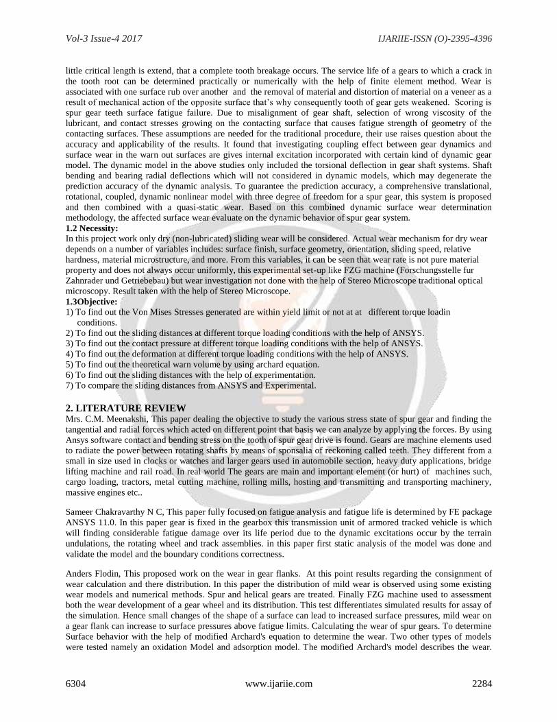
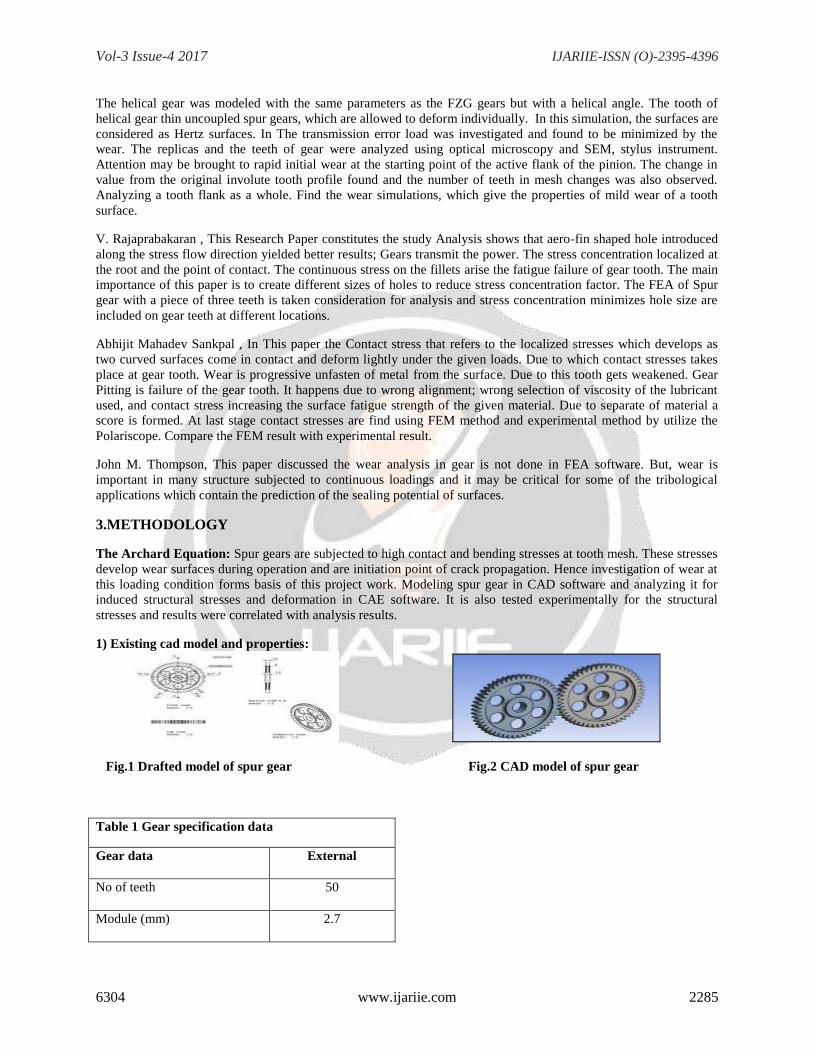
1) Existing cad model and properties:
Fig.1 Drafted model of spur gear Fig.2 CAD model of spur gear
Table 1 Gear specification data
Gear data External
No of teeth 50
Module (mm) 2.7
Page 4
Vol-3 Issue-4 2017 IJARIIE-ISSN (O)-2395-4396
6304 www.ijariie.com 2286
Pitch circle diameter (mm) 135
Addendum of gear (mm) 140
Correction factor 0
Pressure angle 20֩ Stub
Quality of gear 7 Class
Table 3 Wear Classifications and Mechanisms
Classification Wear Mechanisms Wear coefficient K (range)
Wear dominated
by mechanical
behavior of
materials
1. Asperity deformation and
removal
2. Wear caused by plowing
3. Delamination wear
4. Adhesive wear
5. Abrasive wear
6. Fretting wear
7. Wear by solid particle
impingement
10-4
10-4
10-4
10-4
10-2 to 10-1
10-6 to 10-4
-
Wear dominated
by chemical
behavior of
Materials
1. Solution wear
2. Oxidation wear
3. Diffusion wear
4. Wear by melting of the surface
layer
5. Adhesive wear at high
temperatures
2) Finite element analysis:
It is a numerical technique for finding approximate solutions to boundary value problems for partial differential
equations. It is also referred to as finite element analysis (FEA). FEM subdivides a large problem into smaller,
simpler, parts, called finite elements.
Discretization and mesh generation of model
Table 2 Mechanical Properties of alloy steel
(20MnCr5)
Properties Values Unit
Young’s Modulus 2 x10⁵
N/MM2
Tensile Strength 650-880 Mpa
Elongation 8-25 %
Fatigue 275 Mpa
Yield Strength 520 Mpa
Poisons Ratio 0.3 -
Density 7850 Kg/M3
Page 5
Vol-3 Issue-4 2017 IJARIIE-ISSN (O)-2395-4396
6304 www.ijariie.com 2287
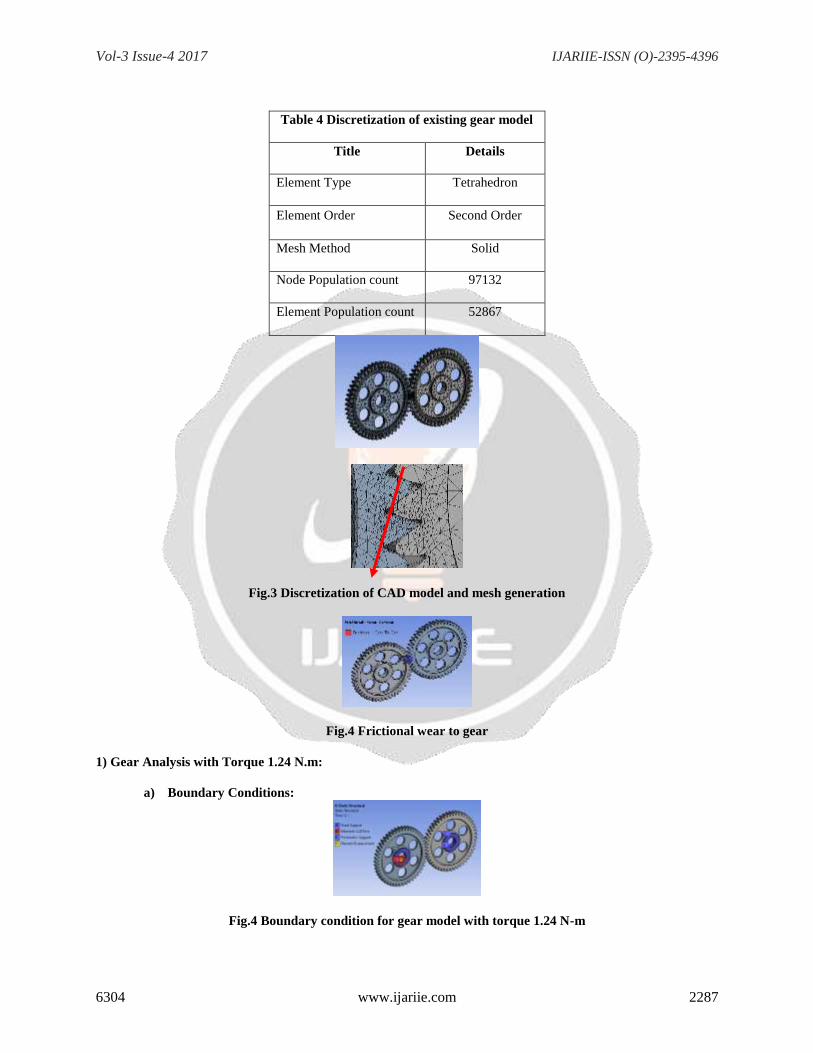
Table 4 Discretization of existing gear model
Title Details
Element Type Tetrahedron
Element Order Second Order
Mesh Method Solid
Node Population count 97132
Element Population count 52867
Fig.3 Discretization of CAD model and mesh generation
Fig.4 Frictional wear to gear
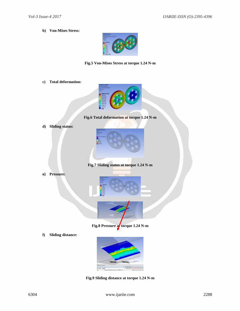
1) Gear Analysis with Torque 1.24 N.m:
a) Boundary Conditions:
Fig.4 Boundary condition for gear model with torque 1.24 N-m
Page 6
Vol-3 Issue-4 2017 IJARIIE-ISSN (O)-2395-4396
6304 www.ijariie.com 2288
b) Von-Mises Stress:
Fig.5 Von-Mises Stress at torque 1.24 N-m
c) Total deformation:
Fig.6 Total deformation at torque 1.24 N-m
d) Sliding status:
Fig.7 Sliding status at torque 1.24 N-m
e) Pressure:
Fig.8 Pressure at torque 1.24 N-m
f) Sliding distance:
Fig.9 Sliding distance at torque 1.24 N-m
Page 7
Vol-3 Issue-4 2017 IJARIIE-ISSN (O)-2395-4396
6304 www.ijariie.com 2289
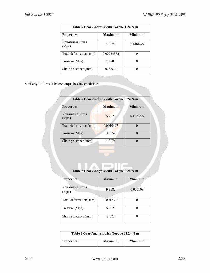
Table 5 Gear Analysis with Torque 1.24 N-m
Properties Maximum Minimum
Von-misses stress
(Mpa) 1.9073 2.1461e-5
Total deformation (mm) 0.00034572
0
Pressure (Mpa) 1.1789 0
Sliding distance (mm) 0.92914
0
Similarly FEA result below torque loading conditions
Table 6 Gear Analysis with Torque 3.74 N-m
Properties Maximum Minimum
Von-misses stress
(Mpa) 5.7528 6.4728e-5
Total deformation (mm) 0.0010427
0
Pressure (Mpa) 3.5559 0
Sliding distance (mm) 1.8574
0
Table 7 Gear Analysis with Torque 6.24 N-m
Properties Maximum Minimum
Von-misses stress
(Mpa) 9.5982 0.000108
Total deformation (mm) 0.0017397
0
Pressure (Mpa) 5.9328 0
Sliding distance (mm) 2.321
0
Table 8 Gear Analysis with Torque 11.24 N-m
Properties Maximum Minimum
Page 8
Vol-3 Issue-4 2017 IJARIIE-ISSN (O)-2395-4396
6304 www.ijariie.com 2290
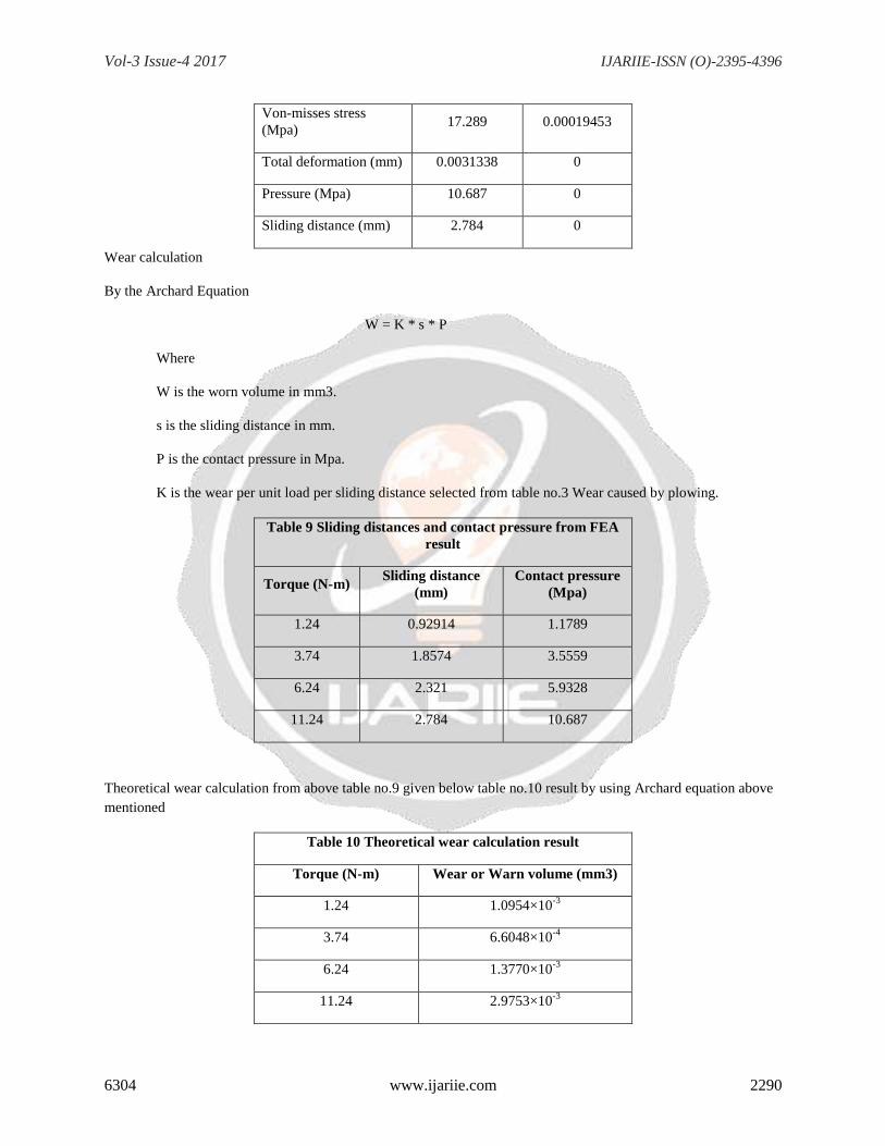
Von-misses stress
(Mpa) 17.289 0.00019453
Total deformation (mm) 0.0031338
0
Pressure (Mpa) 10.687 0
Sliding distance (mm) 2.784
0
Wear calculation
By the Archard Equation
W = K * s * P
Where
W is the worn volume in mm3.
s is the sliding distance in mm.
P is the contact pressure in Mpa.
K is the wear per unit load per sliding distance selected from table no.3 Wear caused by plowing.
Table 9 Sliding distances and contact pressure from FEA
result
Torque (N-m) Sliding distance
(mm)
Contact pressure
(Mpa)
1.24 0.92914 1.1789
3.74 1.8574
3.5559
6.24 2.321 5.9328
11.24 2.784
10.687
Theoretical wear calculation from above table no.9 given below table no.10 result by using Archard equation above
mentioned
Table 10 Theoretical wear calculation result
Torque (N-m) Wear or Warn volume (mm3)
1.24 1.0954×10⁻³
3.74 6.6048×10⁻⁴
6.24 1.3770×10⁻³
11.24 2.9753×10⁻³
Page 9
Vol-3 Issue-4 2017 IJARIIE-ISSN (O)-2395-4396
6304 www.ijariie.com 2291
3 Experimental analysis: Gear manufacturers have so far been occupied with failure due to high root stress,
misalignments of gear shaft, chemical interactions between two bodies, high surface pressure and hardening cracks;
they have neglected investigation of mild wear and its connection to more types of damages. Surface fatigue is
known problem and the cure for it has been better and purer materials, smoother surface, heat treated etc.
In this experimentation only dry (non-lubricated) sliding wear will be considered. Actual wear mechanism for dry
wear depends on a number of variables includes: surface finish, surface geometry, orientation, sliding speed, relative
hardness, material microstructure, and more. From this variables, it can be seen that wear rate is not pure material
property and does not always occur uniformly, this experimental set-up like FZG machine (Forschungsstelle fur
Zahnrader und Getriebebau) but wear investigation not done with the help of 3D stylus instrument and both SEM
and traditional optical microscopy. Result taken with the help of Stereo microscope and image analysis instrument.
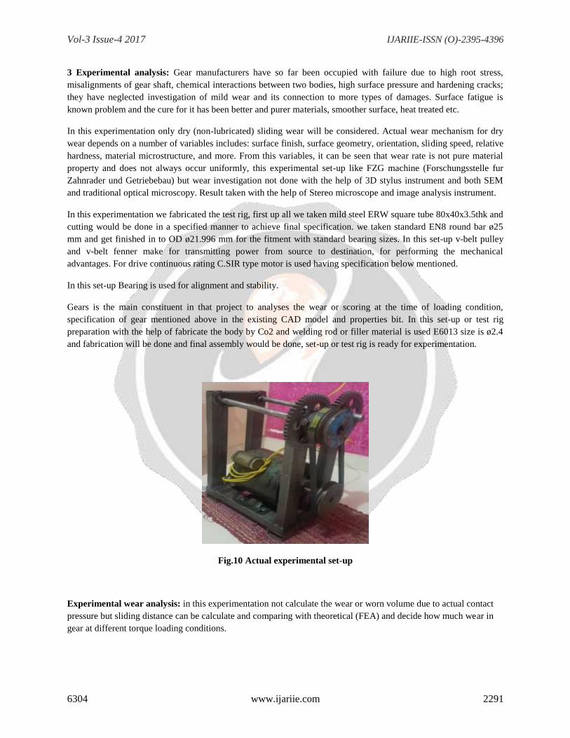
In this experimentation we fabricated the test rig, first up all we taken mild steel ERW square tube 80x40x3.5thk and
cutting would be done in a specified manner to achieve final specification. we taken standard EN8 round bar ø25
mm and get finished in to OD ø21.996 mm for the fitment with standard bearing sizes. In this set-up v-belt pulley
and v-belt fenner make for transmitting power from source to destination, for performing the mechanical
advantages. For drive continuous rating C.SIR type motor is used having specification below mentioned.
In this set-up Bearing is used for alignment and stability.
Gears is the main constituent in that project to analyses the wear or scoring at the time of loading condition,
specification of gear mentioned above in the existing CAD model and properties bit. In this set-up or test rig
preparation with the help of fabricate the body by Co2 and welding rod or filler material is used E6013 size is ø2.4
and fabrication will be done and final assembly would be done, set-up or test rig is ready for experimentation.
Fig.10 Actual experimental set-up
Experimental wear analysis: in this experimentation not calculate the wear or worn volume due to actual contact
pressure but sliding distance can be calculate and comparing with theoretical (FEA) and decide how much wear in
gear at different torque loading conditions.
Page 10
Vol-3 Issue-4 2017 IJARIIE-ISSN (O)-2395-4396
6304 www.ijariie.com 2292
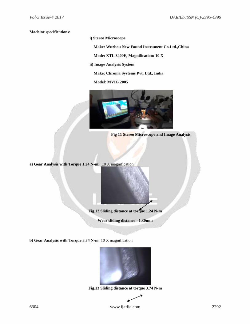
Machine specifications:
i) Stereo Microscope
Make: Wuzhou New Found Instrument Co.Ltd.,China
Mode: XTL 3400E, Magnification: 10 X
ii) Image Analysis System
Make: Chroma Systems Pvt. Ltd., India
Model: MVIG 2005
Fig 11 Stereo Microscope and Image Analysis
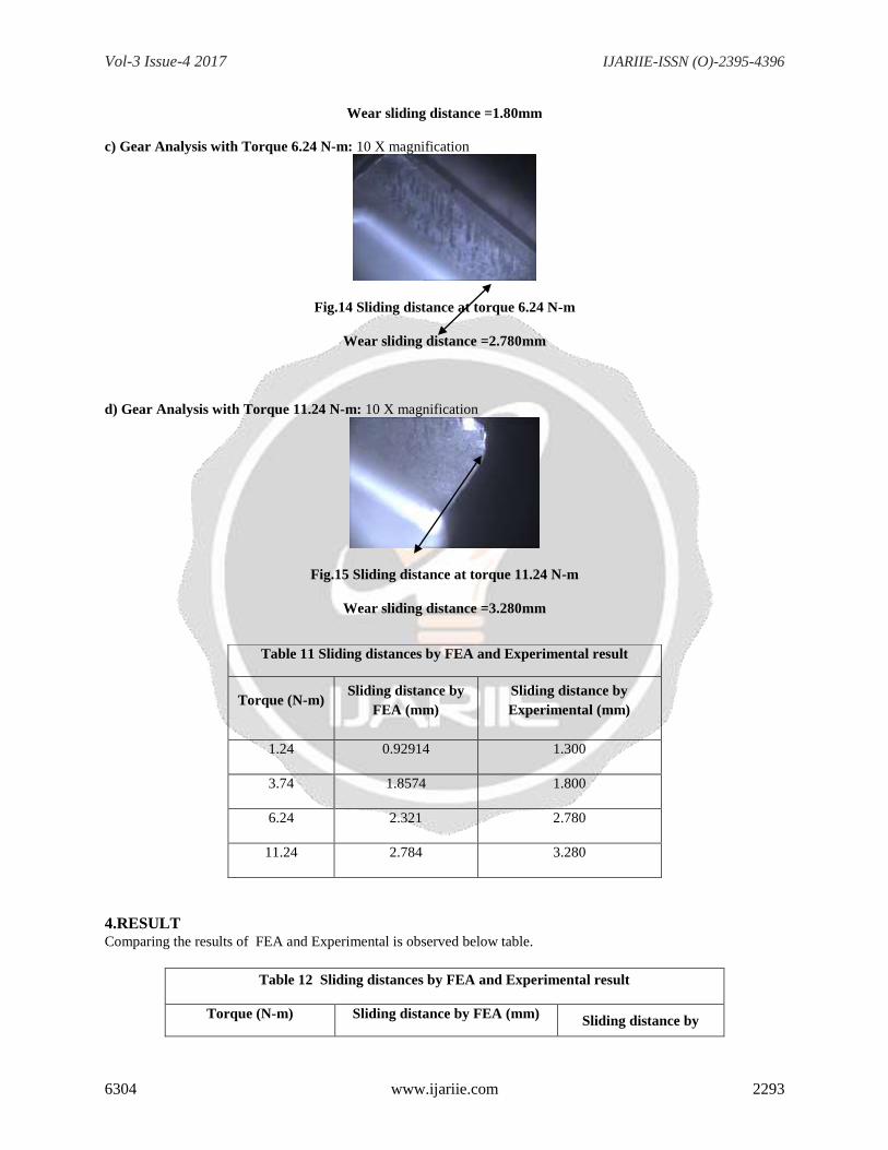
a) Gear Analysis with Torque 1.24 N-m: 10 X magnification
Fig.12 Sliding distance at torque 1.24 N-m
Wear sliding distance =1.30mm
b) Gear Analysis with Torque 3.74 N-m: 10 X magnification
Fig.13 Sliding distance at torque 3.74 N-m
Page 11
Vol-3 Issue-4 2017 IJARIIE-ISSN (O)-2395-4396
6304 www.ijariie.com 2293
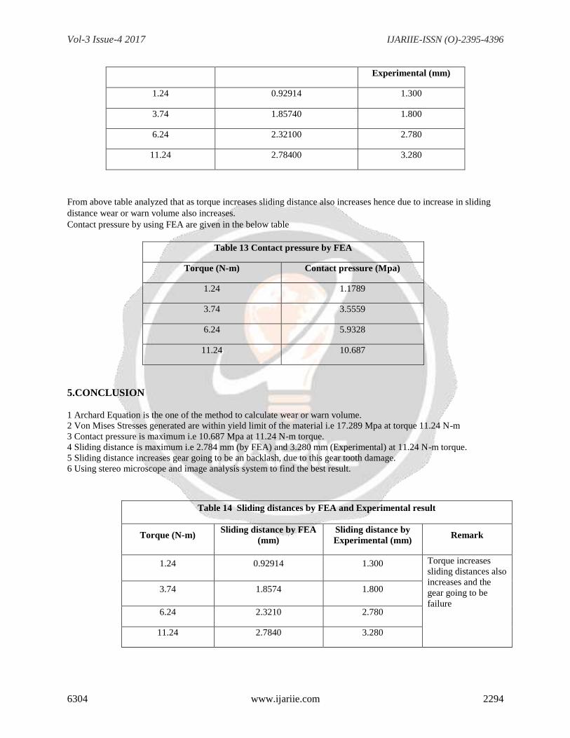
Wear sliding distance =1.80mm
c) Gear Analysis with Torque 6.24 N-m: 10 X magnification
Fig.14 Sliding distance at torque 6.24 N-m
Wear sliding distance =2.780mm
d) Gear Analysis with Torque 11.24 N-m: 10 X magnification
Fig.15 Sliding distance at torque 11.24 N-m
Wear sliding distance =3.280mm
4.RESULT Comparing the results of FEA and Experimental is observed below table.
Table 12 Sliding distances by FEA and Experimental result
Torque (N-m) Sliding distance by FEA (mm) Sliding distance by
Table 11 Sliding distances by FEA and Experimental result
Torque (N-m) Sliding distance by
FEA (mm)
Sliding distance by
Experimental (mm)
1.24 0.92914 1.300
3.74 1.8574
1.800
6.24 2.321 2.780
11.24 2.784
3.280
Page 12
Vol-3 Issue-4 2017 IJARIIE-ISSN (O)-2395-4396
6304 www.ijariie.com 2294
Experimental (mm)
1.24 0.92914 1.300
3.74 1.85740
1.800
6.24 2.32100 2.780
11.24 2.78400
3.280
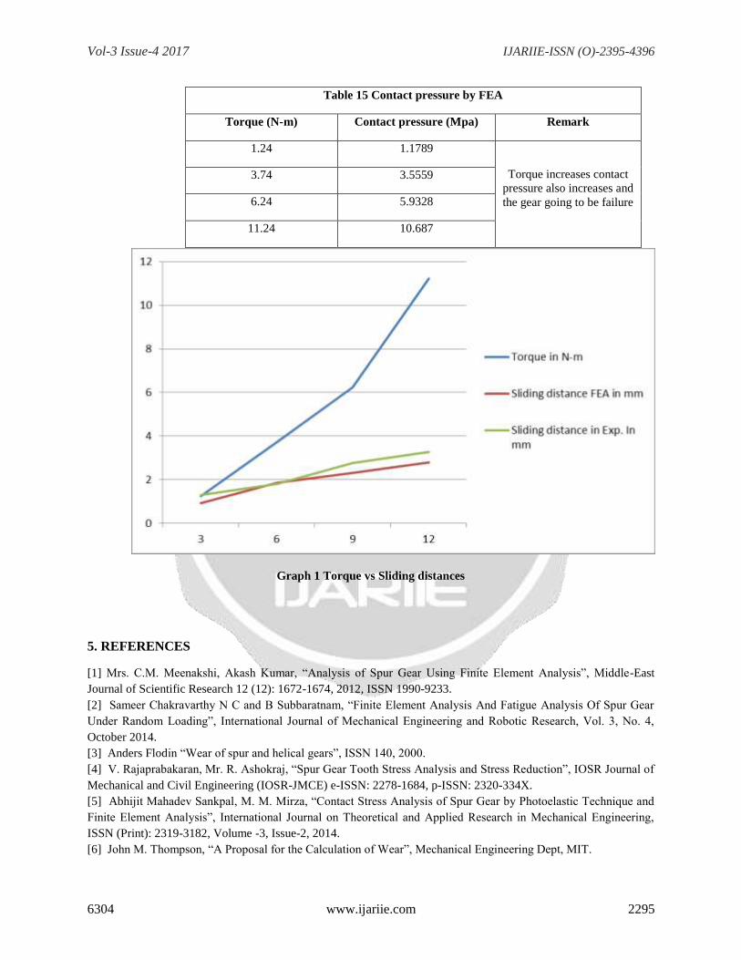
From above table analyzed that as torque increases sliding distance also increases hence due to increase in sliding
distance wear or warn volume also increases.
Contact pressure by using FEA are given in the below table
Table 13 Contact pressure by FEA
Torque (N-m) Contact pressure (Mpa)
1.24 1.1789
3.74 3.5559
6.24 5.9328
11.24 10.687
5.CONCLUSION
1 Archard Equation is the one of the method to calculate wear or warn volume.
2 Von Mises Stresses generated are within yield limit of the material i.e 17.289 Mpa at torque 11.24 N-m
3 Contact pressure is maximum i.e 10.687 Mpa at 11.24 N-m torque.
4 Sliding distance is maximum i.e 2.784 mm (by FEA) and 3.280 mm (Experimental) at 11.24 N-m torque.
5 Sliding distance increases gear going to be an backlash, due to this gear tooth damage.
6 Using stereo microscope and image analysis system to find the best result.
Table 14 Sliding distances by FEA and Experimental result
Torque (N-m) Sliding distance by FEA
(mm)
Sliding distance by
Experimental (mm) Remark
1.24 0.92914 1.300 Torque increases
sliding distances also
increases and the
gear going to be
failure
3.74 1.8574
1.800
6.24 2.3210 2.780
11.24 2.7840
3.280
Page 13
Vol-3 Issue-4 2017 IJARIIE-ISSN (O)-2395-4396
6304 www.ijariie.com 2295
Table 15 Contact pressure by FEA
Torque (N-m) Contact pressure (Mpa) Remark
1.24 1.1789
Torque increases contact
pressure also increases and
the gear going to be failure
3.74 3.5559
6.24 5.9328
11.24 10.687
Graph 1 Torque vs Sliding distances
5. REFERENCES
[1] Mrs. C.M. Meenakshi, Akash Kumar, “Analysis of Spur Gear Using Finite Element Analysis”, Middle-East
Journal of Scientific Research 12 (12): 1672-1674, 2012, ISSN 1990-9233.
[2] Sameer Chakravarthy N C and B Subbaratnam, “Finite Element Analysis And Fatigue Analysis Of Spur Gear
Under Random Loading”, International Journal of Mechanical Engineering and Robotic Research, Vol. 3, No. 4,
October 2014.
[3] Anders Flodin “Wear of spur and helical gears”, ISSN 140, 2000.
[4] V. Rajaprabakaran, Mr. R. Ashokraj, “Spur Gear Tooth Stress Analysis and Stress Reduction”, IOSR Journal of
Mechanical and Civil Engineering (IOSR-JMCE) e-ISSN: 2278-1684, p-ISSN: 2320-334X.
[5] Abhijit Mahadev Sankpal, M. M. Mirza, “Contact Stress Analysis of Spur Gear by Photoelastic Technique and
Finite Element Analysis”, International Journal on Theoretical and Applied Research in Mechanical Engineering,
ISSN (Print): 2319-3182, Volume -3, Issue-2, 2014.
[6] John M. Thompson, “A Proposal for the Calculation of Wear”, Mechanical Engineering Dept, MIT.
Page 14
Vol-3 Issue-4 2017 IJARIIE-ISSN (O)-2395-4396
6304 www.ijariie.com 2296
[7] P.B.Pawar, Abhay A Utpat, “Analysis of Composite Material Spur Gear under Static Loading Condition”, 4th
International Conference on Materials Processing and Characterization, Materials Today: Proceedings 2 (2015) 2968
– 2974.
[8] M. Masjedi and M. M. Khonsari, “On the prediction of Steady-State Wear Rate in Spur Gears”, Louisiana State
University, Department of Mechanical and Industrial Engineering, 2508 Patrick Taylor Hall, 2005.
[9] Xianzeng Liu, YuhuYang, JunZhang, “Investigation on coupling effects between surface wear and dynamics in
a spur gear system”, Tribology International 101(2016)383–394.
[10] Miryam B. Sanchez, Miguel Pleguezuelos, José I. Pedrero, “Approximate equations for the meshing stiffness
and the load sharing ratio of spur gears including hertzian effects”, Mechanism and Machine Theory 109 (2017)
231–249.
[11] John M. Thompson, “A Proposal for the Calculation of Wear”, Mechanical Engineering Dept, MIT.
[12]Mert Şafak Tunalioğlu, BedriTuç, “A new method for preventing premature pitting formation on spur gears”,
Technical Education Faculty, Selcuk University, Konya 42250, Turkey, Department of Mechanical Engineering,
Selcuk University, Konya 42250, Turkey, Engineering Fracture Mechanics 75 (2008) 4431–4438.
[13] Gwidon P. Stachowiak, Gwidon W. Stachowiak, Pawel Podsiadlo, “Automated classification of wear particles
based on their surface texture and shape features”, Tribology Laboratory, School of Mechanical Engineering,
University of Western Australia, 35 Stirling Hwy, Crawley, WA 6009, Australia, Tribology International 41 (2008)
34-43.
[11] Dassault systems user manual.
![“CFD ANALYSIS HELICAL COIL HEAT EXCHANGER”ijariie.com/AdminUploadPdf/CFD_ANALYSIS_HELICAL_COIL_HEAT_E… · Shinde Digvijay D. et al. [3] studied the experimental investigation](https://static.documents.pub/doc/80x56/5fa1c8c0022f2e4c0b162c6a/aoecfd-analysis-helical-coil-heat-exchangera-shinde-digvijay-d-et-al-3-studied.jpg)


