Purdue University Purdue University Purdue e-Pubs Purdue e-Pubs International Refrigeration and Air Conditioning Conference School of Mechanical Engineering 2021 Experimental Investigation of a Domestic Refrigeration Appliance Experimental Investigation of a Domestic Refrigeration Appliance Based on Exergy Destruction Based on Exergy Destruction Mehrdad Taghavi Tampere university, Finland, mehrdad.taghavi@tuni.fi Maria Goossens Seppo Syrjala Tero Joronen Follow this and additional works at: https://docs.lib.purdue.edu/iracc Taghavi, Mehrdad; Goossens, Maria; Syrjala, Seppo; and Joronen, Tero, "Experimental Investigation of a Domestic Refrigeration Appliance Based on Exergy Destruction" (2021). International Refrigeration and Air Conditioning Conference. Paper 2205. https://docs.lib.purdue.edu/iracc/2205 This document has been made available through Purdue e-Pubs, a service of the Purdue University Libraries. Please contact [email protected] for additional information. Complete proceedings may be acquired in print and on CD-ROM directly from the Ray W. Herrick Laboratories at https://engineering.purdue.edu/Herrick/Events/orderlit.html
Transcript
Purdue University Purdue University
Purdue e-Pubs Purdue e-Pubs
International Refrigeration and Air Conditioning Conference School of Mechanical Engineering
2021
Experimental Investigation of a Domestic Refrigeration Appliance Experimental Investigation of a Domestic Refrigeration Appliance
Based on Exergy Destruction Based on Exergy Destruction
Follow this and additional works at: https://docs.lib.purdue.edu/iracc
Taghavi, Mehrdad; Goossens, Maria; Syrjala, Seppo; and Joronen, Tero, "Experimental Investigation of a Domestic Refrigeration Appliance Based on Exergy Destruction" (2021). International Refrigeration and Air Conditioning Conference. Paper 2205. https://docs.lib.purdue.edu/iracc/2205
This document has been made available through Purdue e-Pubs, a service of the Purdue University Libraries. Please contact [email protected] for additional information. Complete proceedings may be acquired in print and on CD-ROM directly from the Ray W. Herrick Laboratories at https://engineering.purdue.edu/Herrick/Events/orderlit.html
Since refrigeration appliances consume more than 15% of electrical energy over the globe, many solutions have been proposed to enhance the efficiency of these appliances. However, the solutions mostly rise the expenditure and complexity of the appliances, making these methods less feasible for manufacturing. Therefore, some inexpensive and less complicated modifications should be proposed to enhance the efficiency and performance of the appliances affordably. This paper presents a new solution using unutilized cooling capacity of evaporator for cooling compressor. The experimental exergy analysis of a domestic refrigerator in which the suction pipe absorbs heat from the compressor shell illustrates a 12.64% reduction in total irreversibility, as well as a 5% and 4% of increase in cooling capacity and coefficient of performance, respectively. Moreover, the appliance with the modified cycle needs 18.2% less refrigerant than the normal design. This idea would be an affordable and practical way to enhance the efficiency of refrigeration appliances as well as decrease the manufacturing costs. This study proposes recommended design guidelines for more efficient refrigeration appliances to be used in designing compressors.
1. INTRODUCTION
Nowadays, compression refrigeration cycle (CRC) is widely used in domestic, commercial, and industrial appliances and systems for heating and cooling processes as approximately 15% of the electrical energy is consumed by such systems, globally (Fichman, 2012). Hence, many efforts have been performed to achieve higher efficiency and less energy consumption in the cycle. The achievement in saving energy declines the energy costs for buildings and industries. In addition, since power plants mostly rely on fossil fuels to produce electrical energy (Daioglou et al., 2012), energy saving in such appliances would be an effective way against CO2 emissions and global warming.
Exergy analysis is a standard approach to assess the efficiency of components in a thermodynamics cycle. In this analysis, irreversibility I which is the difference between the reversible work and actual work in a control volume (CV), is calculated for all the components. By comparing the results, the most inefficient components which should be considered for modifications can be found. Rangel-Hernández et al. (2019) performed exergy and energy analysis on a domestic refrigerator with different charge amounts. They argued compressor has the most exergy destruction among other components as almost 60% of the total irreversibility of the cycle is due to the compressor. This claim has also been declared by Joybari et al. (2013) which is another experimental exergy analysis on a household refrigerator. They claimed more than 74% of total exergy destruction in a domestic refrigeration appliance is due to the compressor followed by the condenser, capillary tube, evaporator, and superheating coil. However, the results of this study are affected by time since the compartment temperature had not been stabilized when the cycle was analyzed. To have a more accurate evaluation of efficiency in the components, the cycle should be analyzed in steady-state when the inner temperature of the appliance is constant. Mota-Babiloni et al. (2018) argued that after the compressor, the evaporator is ranked second among all components considering their contribution to total exergy destruction. After the evaporator, condenser, and expansion valve are other causes of entropy generation in the cycle.
Working condition of the cycle affects the relative reversibility (RI) which shows the share of each component from the total irreversibility in a CRC. however, compressor mostly has the highest RI among all the parts. Shikalgar & Sapali (2019) illustrated a cycle in which the evaporator is colder than -17.5◦C, the expansion device has the highest exergy loss after the compressor. The condenser is ranked third among the components in such the appliances. (Gullo et al., 2016) claimed evaporators are more inefficient than the expansion valves in a parallel CRC. This study also argued despite the fact that condenser has less efficiency than each evaporator, the total exergy destruction in both
18th International Refrigeration and Air Conditioning Conference at Purdue, May 24-27, 2021
evaporators is higher than the condenser. However, exergy destruction in the suction pipe has been ignored in these studies, while there is a significant irreversibility due to heat transfer to ambient or internal heat exchanger (IHX). In addition, refrigerant is also considered as an effective parameter on the RI of components. Gill et al. (2019) investigated components RI in the cycle when it works with 450a and R134a as the refrigerant. Although the results show a significant improvement in the compressor performance using R450a instead of R134a, RI increases in the capillary tube, condenser, and evaporator by the replacement. Joybari et al. (2013) show replacing R134a with R600a increases RI of compressor in a domestic refrigeration appliance, while the RI values of other components significantly decrease. This study also illustrates the superheating coil has lower irreversibility using R134a. As a result, replacing the refrigerant is not always a suitable solution to decrease the irreversibility of all components in a CRC.
Like the domestic refrigeration appliances, in air conditioning systems, compressor has the highest percentage of exergy loss (Golzari et al., 2017); (Kabeel et al., 2016); (Jemaa et al., 2016); (Li et al., 2014). However, Pérez-García et al. (2017) argued that RI of compressor in a CRC depends on the isentropic efficiency of compressor. They studied CRC in a mobile air conditioning system and claimed when the isentropic efficiency of the compressor is less than 60%, the compressor has the highest inefficiency, while beyond 60% condenser has the most RI in the cycle. In some studies, it has been argued that evaporator has the lowest exergy destruction (Golzari et al., 2017); (Jemaa et al., 2016); (Li et al., 2014)), while Kabeel et al., (2016) claimed evaporator has higher exergy loss than expansion valve in an air conditioning system. However, this study has analyzed the cycle when the evaporator has above zero temperature, while many refrigeration appliances work at below zero temperature of evaporation. Yataganbaba et al. (2015) investigated the effect of evaporation pressure on the performance of the evaporator and expansion valve. Their study shows that when the evaporator temperature is -5 ◦C, the expansion valve and evaporator have approximately the same exergy destruction, while at -18 ◦C, the exergy loss in the expansion valve is almost two times more than the evaporator. However, Kabeel et al. (2016) claimed that the evaporator has significantly higher exergy destruction than the expansion valve.
According to the aforementioned studies, compressor is the most inefficient component among other parts in CRC. Hence, improving the efficiency of compressors has been studied in many projects. Cooling the compressor using an external cooler to have an isothermal compression process in the compressor was studied by Wang et al. (2008). Utilization of nanomaterials in compressor oil is also suggested as another possible way to enhance the performance of compressors (Selimefendigil, 2019). Although the results of these studies illustrate a significant decrease in energy consumption of compressors, these solutions impose extra expenditure on manufacturing and maintenance of the appliances. Utilization of defrosting drips is a simple and practical way to absorb heat from the compressor shell (Nethaji & Mohideen, 2017). This method can provide 8-10% of energy saving for the compressor but can work as long as there is water on the compressor shell. Since the defrost process can not supply water continuously, this solution can not permanently absorb the heat from the compressor.
Despite many studies in exergy analysis of CRC, heat transfer from the compressor shell to ambient has been mostly ignored, while Hopfgartner et al. (2016) shows there is a significant heat transfer from the compressor to ambient that affects the outlet temperature. Hence, to achieve higher accuracy in the calculation of compressor irreversibility, both heat transfer and inlet work should be considered in the equations. Furthermore, an affordable and practical solution to increase the efficiency of compressor avoiding costly methods should be proposed. The aim of this paper is to evaluate the exergy analysis of a domestic appliance considering heat transfer from the compressor as well as presenting an inexpensive method to enhance the efficiency of the appliance. In this paper, we argue that removing heat transfer between capillary tube and suction pipe and using unutilized cooling capacity in the pipe for cooling compressor in a domestic refrigerator decreases total irreversibility and charge amount by 12.64% and 18.4% respectively while the COP increases by 4%.
2. METHODOLOGY
2.1 Experimental setup A domestic refrigerator with the traditional design (Fig1.a) was used in the case study. In this design, an IHX between the suction pipe and capillary tube evaporates any remaining liquid refrigerant in the suction pipe and cools refrigerant before the expansion process (Fig 2). As a result, the compressor is protected from receiving liquid refrigerant and refrigerant has less quality in the evaporator.
The experimental investigations were performed at a laboratory that is accredited by Administration standards of
18th International Refrigeration and Air Conditioning Conference at Purdue, May 24-27, 2021
3
Suction pipe
~ cp
Temperature sensor
Pressure probe
81 Compressor
Q condenser
M Evaporator
- Capilla,, , tube
~ Fi ller dryer
Suction pipe
1
2632, Page 3
Khorasan Razavi, Iran according to standard (IEC 62552-3:2015/AMD1:2020, 2020). However, temperature of the test room was set at +25◦C due to some restrictions in providing standard ambient temperature (+32◦C). PT100 sensors with ±0.1◦C of accuracy were used to measure temperature T of the compartment as well as the refrigerant at the inlet and outlet of each component. Since in this study temperature sensors were placed on the pipes, the sensors would be affected by ambient temperature that causes inaccuracy in measuring the temperatures. To minimize the risk, the sensors were covered with polyethylene insulator at the measuring points in the components. The pressure of refrigerant p in the cycle was measured using TESTO 549i pressure probes with 0.68 kPa of accuracy. The positions of temperature sensors and pressure probes are illustrated in Fig.1. Because of the limited number of available pressure probes at the laboratory and risk of leakage using several probes in the cycle, we used two pressure probes, which were installed at the compressor inlet and outlet.
By having the pressure and temperature of refrigerant and using the table of thermophysical properties of the refrigerant ASHRAE (2009), we can find enthalpyh and entropy s of the refrigerant at inlet and outlet of the components. The electrical power of the compressor, W , was measured with an energy meter with an accuracy of ± 0.1 W.
(a) Modified cycle. (b) Normal cycle.
Figure 1: Schematic of the cycles.
The proposed modified cycle is shown in Fig 1.a. Unlike the traditional design (Fig 1.b), there is no heat transfer Q
between the capillary tube and suction pipe in the modified cycle. Instead, the suction pipe cools the compressor shell, as can be seen in Fig 1.a and Fig 3. Using aluminium tape on the suction pipe in the experimental setup, we tried to increase the heat transfer between the compressor and suction pipe. We expected to have more mass flow rate, m , due to the modification, the cycle needs a shorter capillary rube. As a result, the capillary tube was shortened by 1.7m in the modified cycle. Moreover, having IHX between the suction line and capillary tube needs a long suction pipe in the cycle. Thus, by removing the IHX in the modified cycle, the suction pipe in the modified cycle has 1m less length than the normal cycle.
Figure 2: Internal heat transfer between the capillary tube and suction pipe.
Figure 3: Heat transfer between the suction line and compressor.
18th International Refrigeration and Air Conditioning Conference at Purdue, May 24-27, 2021
I I I I
2632, Page 4
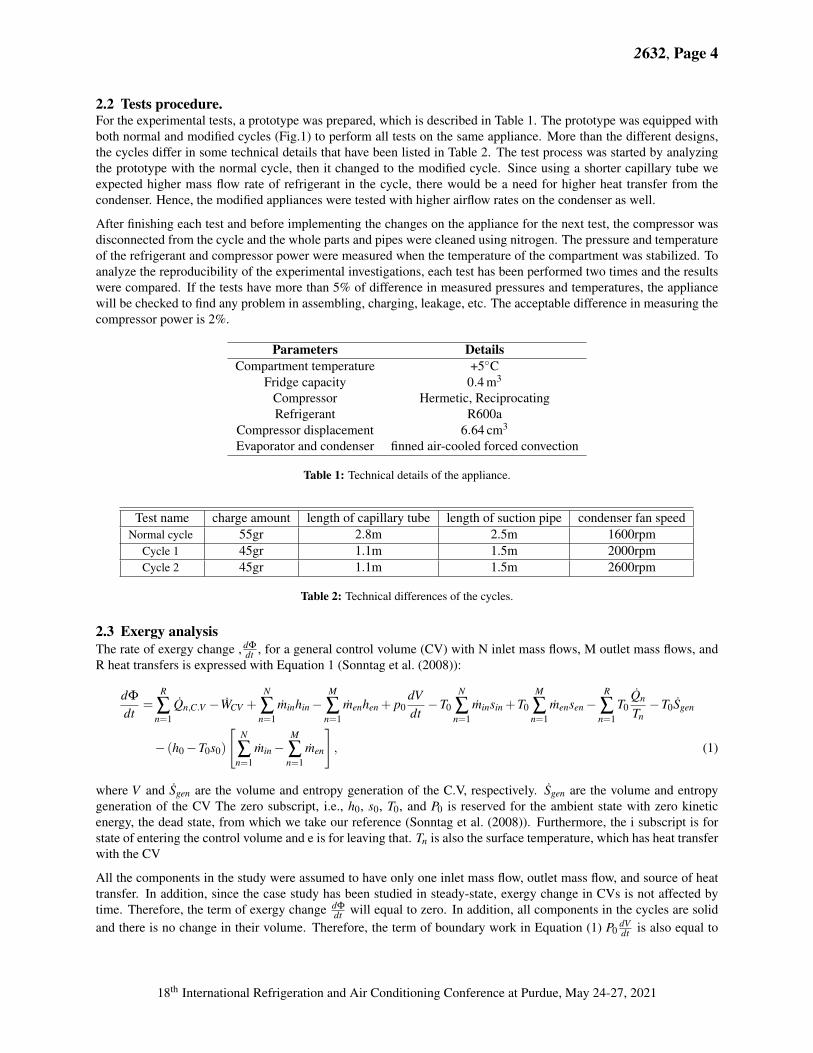
2.2 Tests procedure. For the experimental tests, a prototype was prepared, which is described in Table 1. The prototype was equipped with both normal and modified cycles (Fig.1) to perform all tests on the same appliance. More than the different designs, the cycles differ in some technical details that have been listed in Table 2. The test process was started by analyzing the prototype with the normal cycle, then it changed to the modified cycle. Since using a shorter capillary tube we expected higher mass flow rate of refrigerant in the cycle, there would be a need for higher heat transfer from the condenser. Hence, the modified appliances were tested with higher airflow rates on the condenser as well.
After finishing each test and before implementing the changes on the appliance for the next test, the compressor was disconnected from the cycle and the whole parts and pipes were cleaned using nitrogen. The pressure and temperature of the refrigerant and compressor power were measured when the temperature of the compartment was stabilized. To analyze the reproducibility of the experimental investigations, each test has been performed two times and the results were compared. If the tests have more than 5% of difference in measured pressures and temperatures, the appliance will be checked to find any problem in assembling, charging, leakage, etc. The acceptable difference in measuring the compressor power is 2%.
Table 1: Technical details of the appliance.
Parameters Details Compartment temperature
Fridge capacity Compressor Refrigerant
Compressor displacement Evaporator and condenser
+5◦C 3 0.4 m
Hermetic, Reciprocating R600a
3 6.64 cmfinned air-cooled forced convection
Table 2: Technical differences of the cycles.
Test name charge amount length of capillary tube length of suction pipe condenser fan speed Normal cycle 55gr 2.8m 2.5m 1600rpm
2.3 Exergy analysis The rate of exergy change , ddt
Φ , for a general control volume (CV) with N inlet mass flows, M outlet mass flows, and R heat transfers is expressed with Equation 1 (Sonntag et al. (2008)):
R N M N M R ˙dΦ dV QnT0 − T0∑ Qn,C.V −WCV + ∑ m inhin − ∑ ∑ m insin + T0 ∑ m ensen − ∑ S gen m enhen + p0 − T0= dt dt Tnn=1 n=1 n=1 n=1 n=1 n=1[ ]
m en , (1) N M
∑ m in − ∑ n=1 n=1
− (h0 − T0s0)
where V and S gen are the volume and entropy generation of the C.V, respectively. S gen are the volume and entropy generation of the CV The zero subscript, i.e., h0, s0, T0, and P0 is reserved for the ambient state with zero kinetic energy, the dead state, from which we take our reference (Sonntag et al. (2008)). Furthermore, the i subscript is for state of entering the control volume and e is for leaving that. Tn is also the surface temperature, which has heat transfer with the CV
All the components in the study were assumed to have only one inlet mass flow, outlet mass flow, and source of heat transfer. In addition, since the case study has been studied in steady-state, exergy change in CVs is not affected by time. Therefore, the term of exergy change dΦ will equal to zero. In addition, all components in the cycles are soliddt
dV and there is no change in their volume. Therefore, the term of boundary work in Equation (1) P0 dt is also equal to
18th International Refrigeration and Air Conditioning Conference at Purdue, May 24-27, 2021
Control smtace ·------------------------------------------------: / Q 'LJ Control smface
zero. As a result, Equation (1) changes to Equation (2) for an CRC.
QT CV
0S gen = QCV −WCV + m ihi − m ehe − T0m isi + T0m ese − T0 − (h0 − T0s0)(m i − m e) , (2)T
Irreversibility is directly proportional to the entropy generationSonntag et al. (2008)) which is shown by Equation (3).
I = T0S gen. (3)
In this study, we assumed there is no leakage in the connectors nor between the piston ring and the cylinder wall. It was also assumed the refrigerant is not accumulated in the components. Hence, the mass flow rate of refrigerant at the inlet and outlet of all components are the same, as shown by Equation (4).
m i = m e = m . (4)
By compiling and simplifying Equations (3), (2), and (4) we will get Equation (5) to calculate the amount of irreversibility in each component. ( )
TI 0= ∑ 1 − QCV + m (T0∆s − ∆h) −WCV , (5)
T
where the first term relates to heat transfer, the second term is irreversibility due to the mass flow, and the last term is rate of power to the CV.
2.3.1 Irreversibility in compressor: In this study, pressure and temperature of refrigerant were measured at inlet and outlet of the compressor. However, Hopfgartner et al. (2016) show the temperature of refrigerant changes considerably in the compressor. Due to restrictions in facilities at the laboratory for analyzing the interior heat transfer of the compressor, the compressor was split into two separate control volumes (Fig.4). In the first CV, through an isentropic process, the input refrigerant is compressed (Fig4.a). Then, the compressed refrigerant releases heat to the ambient via an isobaric process in the second CV (Fig 4.b). Hence, total irreversibility of the compressor will be calculated by Equation (6).
∆hheat trans f erI com = −m ˙ ∆hcompression − W CV + mT˙ 0(∆sheattrans f er − ), (6)
Tamb
where the first two term are irreversibility due to compression process and the next two terms are irreversibility due to the heat transfer process.
(a) Compressor as the CV with an isentropic compression process
(b) Compressor as the CV with an isobaric heat transfer
Figure 4: Compressor as the CV
18th International Refrigeration and Air Conditioning Conference at Purdue, May 24-27, 2021
Q=Oi} r··---- - ! P4 ---·---------Ps
' ' ..................................
2632, Page 6
2.3.2 Irreversibility in capillary tube: In the traditional design, there is heat transfer between capillary tube and suction pipe by brazing these two components. Thus, both heat transfer and pressure drop through the capillary tube must be considered. Similar to the compressor, we simplified the capillary tube as the CV by splitting that into two CV In the first CV, through an isobaric process the refrigerant releases heat and in the second C.V, via an isoenthalpic throttling, the refrigerant pressure drops. Having this assumption, the irreversibly in the capillary is calculated by Equation (7).
∆hheat trans f er = ˙ ) (7)Iexp mT0(∆sexp + ∆sheat trans f er −
Tsuction pipe
Since in the modified cycle there is no heat transfer to the capillary tube and we assumed the process as an isoenthalpic throttling, the terms of heat transfer equal zero. Therefore, the irreversibility in the capillary tube will be calculated by Equation (8).
Iexp = ˙ (8)mT0∆s
(a) Capillary tube as the CV considering an isobar heat (b) Capillary tube as the CV considering an transfer process isoenthalpic throttling
Figure 5: Capillary tube as the CV
2.3.3 Irreversibility in evaporator, condenser, and suction pipe: We assumed heat transfer processes happen at constant pressure. QCV is also equal to entropy changes of refrigerant in the CV Therefore, the irreversibility in them will be calculated by Equation (9).
˙ ),Ieva & con & suc = mT0(∆s − ∆h
(9)T
where T is temperature of compartment for evaporator, T0 for condenser, and temperature of capillary tube for suction pipe.
2.3.4 Cooling capacity: Cooling capacity, Q c, of the cycles is calculated using Equation (10). Enthalpy changes in evaporator is obtained by measuring the temperature and pressure at inlet and outlet of evaporator as well as using thermophysical properties of the refrigerant ASHRAE (2009).
Q c = m .∆heva (10)
2.3.5 COP of the appliance: The most important parameter, which is considered to analyze the performance of CRC in both heating and cooling appliances is COP. As it has been represented by (Sonntag et al. (2008)) , COP in a cooling refrigeration appliance is a function of cooling capacity and electrical power of compressor, Wcom. Hence, COP is calculated with Equation (11).
QcCOP = (11)Wcom
2.3.6 Mass flow rate: According to Equation (4), mass flow rate of refrigerant in all components of the cycle is constant. Therefore, calculating the mass flow at a specific point in the cycle, we will have the m in all equations (5)-(11). For calculating the m , we need the compressor displacement, rotational speed of motor in the compressor, and density of refrigerant at compressor suction pipe. Displacement of the compressor is mentioned in Table 1, which can be found in the compressor datasheet. An optical tachometer was used to measure the rotational speed of the compressor in a real working condition. Thus, mass flow rate of compressor is obtained from Equation (12).
m = ω.dis.ρ (12)
18th International Refrigeration and Air Conditioning Conference at Purdue, May 24-27, 2021
0.035
Vl ..__ 0.030
32' ~ 0.025 ..... := 0.020 .0 -~ 0.015
Q)
~ 0.010 ,._ ,._ - 0.005
0.000
Normal cycle Cyclel
l!8!!8!I compressor
"""""' suction pipe - evaporator 1111B condenser
~ expansion
Cycle2
2632, Page 7
3. RESULTS AND DISCUSSIONS
3.1 T-S diagram The laboratory results are used to plot the T-S diagram for the three cycles as it is illustrated in Fig 6. 1-1* is a compression process in the compressor through an isentropic process as illustrated in Fig4.a. It can be found from the diagram that the compressor outlet temperatures (point 2) in cycles 1 and 2 are closer to the saturated line. The reasons for the condition are both absorbing the heat from the compressor shell with suction pipe and receiving the refrigerant at a lower temperature in the compressor(point 1). In addition, comparing point 5 in the cycles shows cooling the refrigerant in IHX (process 3-4) significantly decreases the quality of refrigerant in the evaporator. On the other hand, IHX increases temperature of refrigerant at the compressor suction that dramatically decreases the density of refrigerant received by the compressor ASHRAE (2009).
Normal cyclecycle 1cycle 2Normal cyclecycle 1cycle 2
2.30 2.31 2.32 2.33 2.34 2.35 2.36s [kJ/kg K]
306
308
310
312
314
316
Tempe
rature T / K 2
Figure 6: TS diagrams of the cycles
3.2 Irreversibility in components Figure 7 illustrates the irreversibility of each part in the cycle, as well as the total irreversibility of the cycles. Similar to other studies in the field (Rangel-Hernández et al. (2019), Joybari et al. (2013), Rangel-Hernández et al. (2019), Mota-Babiloni et al. (2018)), compressor has the highest irreversibility among other parts. Removing the IHX and cooling the compressor with the suction pipe decreases the irreversibility in the compressor and evaporator, as well as the total irreversibility of the cycle. However, the changes rise the irreversibility in the suction pipe, capillary tube, and condenser. Comparing Fig 6 and Fig 7.a shows sub-cooled refrigerant at the outlet of condenser provides less irreversibility in the capillary tube. The results also illustrate decreasing the outlet temperature of the condenser by 5◦C leads to a 20.2% decline in irreversibility of the capillary tube.
Normal Cycle Cycle 1 Cycle 2
0.054
0.055
0.056
0.057
0.058
Tota
l irre
vers
ibili
ty (
kJ/s
)
(a) Irreversibility in the components (b) Irreversibility in the cycles
Figure 7: Irreversibility in the components and cycles
18th International Refrigeration and Air Conditioning Conference at Purdue, May 24-27, 2021
LL
2632, Page 8
3.3 Cooling capacity: Cooling capacities of the cycles have been compared in Fig 8. Comparing cooling capacities of normal cycle and cycle 1 shows that removing the IHX without increasing the airflow rate on the condenser dramatically decreases the cooling capacity of the appliance. The reason can be found by comparing Fig 9 that shows the mass flow rate of refrigerant in each cycle with Fig6. Since removing IHX provides higher mass flow rate of refrigerant (comparing the cycles in Fig 9), the refrigerant absorbs more heat through the evaporator, which should be released through the condenser. Otherwise, the amount of refrigerant quality at the evaporator inlet will decrease as can be found by comparing point 5 in Fig 6 for cycles 1 and 2. Having less amount of refrigerant quality than cycle 1 and higher mass flow rate of refrigerant than normal cycle, cycle 2 has the highest cooling capacity among the cycles as can be seen in Fig 8.
Normal Cycle Cycle 1 Cycle 2
0.26
0.27
0.28
0.29
0.3
Co
olin
g c
ap
acity (
kJ/s
)
Figure 8: Comparison of cooling capacity in the appliance affected by the modifications
Normal Cycle Cycle 1 Cycle 2
7.5
8
8.5
9
9.5
Ma
ss f
low
ra
te (
kg
/s)
10-4
Figure 9: Variations of refrigerant mass flow rate in the cycles due to the modifications
3.4 Coefficient of performance: COP is calculated to analyze the efficiency of the cycle. According to Equation (11), efficiency of CRC is a function of cooling capacity and compressor power. Figure 10 shows removing IHX and cooling the compressor shell increase the compressor power by only 0.4% and 0.95% in cycle 1 and cycle 2, respectively. However, the modifications considerably change specific work of the compressor as in cycles 1 and 2, the compressor has 11.4% less specific work than the normal cycle. Despite the remarkable drop in the specific work by removing the IHX and cooling the compressor shell, Fig 11 shows the change must be followed by increasing the airflow rate on the condenser to achieve higher COP in the cycle. Removing the IHX, cooling the compressor by suction pipe, and increasing the airflow on the condenser lead to enhance COP by 4%.
65
70
75
80
85
Sp
ecific
wo
rk (
kJ/k
g)
Normal Cycle Cycle 1 Cycle 2
0.065
0.07
0.075
0.08
0.085
To
tal w
ork
(kJ/s
) Total work
specific work
0.0734 0.0737 0.0741
Figure 10: Measured compressor power and calculated specific compressor work in the cycles
Normal Cycle Cycle 1 Cycle 2
3.4
3.5
3.6
3.7
3.8
3.9
4
CO
P
Figure 11: Calculated COP of the appliance using cooling capacity and actual work
3.5 Expenditures As can be seen in Table 2, the modified cycle has 18.2% less refrigerant than the traditional design. Furthermore, the new design needs 60% and 40% shorter capillary tube and suction pipe respectively, while the appliance has higher COP and cooling capacity than the normal design. As a result, the modifications not only improve the performance and efficiency of the cycle, but also decrease the costs of manufacturing. Furthermore, since the modified cycle has almost 14% higher mass flow rate than the normal design, the current compressor could be replaced with a smaller
18th International Refrigeration and Air Conditioning Conference at Purdue, May 24-27, 2021
2632, Page 9
compressor which has lower capacity. As a result, manufacturing cost of the appliance would significantly decrease due to the replacement.
4. CONCLUSION
This study deals with exergy analysis of utilizing unutilized cooling capacity in a domestic refrigeration appliance for cooling compressor as an affordable solution to enhance the efficiency of the appliance. To obtain the required data for the analysis, both modified and traditional cycles were implemented in a household refrigerator and the appliance was tested according to standard procedures. Based on the results, the following remarks have been concluded:
• Compared to traditional design, the modified design provides higher efficiency for the appliance. Implementing the modifications improves the COP of the appliance by approximately 4%. However, this value could be different by changing the cycle size and refrigerant type.
• The improvement not only does not impose any extra costs for manufacturing but also can decrease the expenditures by decreasing the charge amount and length of capillary tube and suction line.
• The performance of the appliance has been improved due to the modifications. The appliance has a shorter pulldown time using the modified cycle. This advantage is important for appliances which must supply a desired temperature in the shortest possible time.
• Since no complicated part or method have been used in the proposed solution, the idea is feasible to be implemented in production lines.
Because of some restrictions of facilities in the laboratory to measure the internal components of the compressor, we ignored the interior heat transfer between the components. Moreover, efficiency of the electrical motor in the compressor has been assumed equal to one. To achieve better accuracy in the analysis, it is recommended to investigate the internal heat transfer and consider efficiency of the electrical motor.
Moreover, due to the difficulty of inserting the suction pipe in the compressor, the suction pipe was placed on the compressor shell making the heat transfer between the pipe and ambient unavoidable. To decrease the undesirable heat transfer, we suggest putting the suction pipe inside the compressor and close to the cylinder.
NOMENCLATUR
Subscript W Total rate of power (kJ/s) eva evaporator w work rate per unit mass (kJ/kg) com compressor Q heat transfer rate (kJ/s) con condenser m mass flow rate (kg/s) exp expansion process h specific enthalpy (kJ/kg) suc suction pipe s specific entropy (kJ/kg.K) amb ambient S gen rate of entropy generation (kJ/s.K) c cold reservoir T temperature (◦K) 0 dead state Φ exergy (kJ) i entering the control volume I irreversibility (kW ) e leaving the control volume dis compressor displacement (cm3) ω rotational speed (rpm) ρ density (kg/m3) p Pressure (kPa)
Daioglou, V., Van Ruijven, B. J., & Van Vuuren, D. P. (2012). Model projections for household energy use in developing countries (Vol. 37; Tech. Rep. No. 1).
18th International Refrigeration and Air Conditioning Conference at Purdue, May 24-27, 2021
Fichman, B. T. (2012). Annual energy review. USDOE Energy Information Administration (EIA), Washington, DC (United States).
Gill, J., Singh, J., Ohunakin, O. S., & Adelekan, D. S. (2019). Exergy analysis of vapor compression refrigeration system using R450a as a replacement of R134a. Journal of Thermal Analysis and Calorimetry, 136(2), 857–872.
Golzari, S., Kasaeian, A., Daviran, S., Mahian, O., Wongwises, S., & Sahin, A. Z. (2017). Second law analysis of an automotive air conditioning system using hfo-1234yf, an environmentally friendly refrigerant. International Journal of Refrigeration, 73, 134–143.
Gullo, P., Elmegaard, B., & Cortella, G. (2016). Advanced exergy analysis of a R744 booster refrigeration system with parallel compression. Energy, 107, 562–571.
Hopfgartner, J., Heimel, M., Berger, E., Posch, S., Almbauer, R., & Stangl, S. (2016). Experimental study on the thermal behavior of a domestic refrigeration compressor during transient operation in a small capacity cooling system.
Household refrigerating appliances characteristics and test methods part 3: Energy consumption and volume [International Standard]. (2020, November).
Jemaa, R. B., Mansouri, R., Boukholda, I., & Bellagi, A. (2016). Energy and exergy investigation of R1234ze as R134a replacement in vapor compression chillers. international journal of hydrogen energy, 30(1), e1–1.
Joybari, M. M., Hatamipour, M. S., Rahimi, A., & Modarres, F. G. (2013). Exergy analysis and optimization of r600a as a replacement of R134a in a domestic refrigerator system. International Journal of refrigeration, 36(4), 1233–1242.
Kabeel, A., Khalil, A., Bassuoni, M., & Raslan, M. (2016). Comparative experimental study of low gwp alternative for R134a in a walk-in cold room. International Journal of Refrigeration, 69, 303–312.
Li, G., Eisele, M., Lee, H., Hwang, Y., & Radermacher, R. (2014). Experimental investigation of energy and exergy performance of secondary loop automotive air-conditioning systems using low-gwp (global warming potential) refrigerants. Energy, 68, 819–831.
Mota-Babiloni, A., Belman-Flores, J. M., Makhnatch, P., Navarro-Esbrí, J., & Barroso-Maldonado, J. M. (2018). Experimental exergy analysis of R513a to replace R134a in a small capacity refrigeration system. Energy, 162, 99–110.
Nethaji, N., & Mohideen, S. T. (2017). Energy conservation in domestic refrigerators by cooling compressor shell–a case study. Case studies in thermal engineering, 10, 382–387.
Pérez-García, V., Belman-Flores, J. M., Rodríguez-Muñoz, J. L., Rangel-Hernández, V., Gallegos-Muñoz, A., et al. (2017). Second law analysis of a mobile air conditioning system with internal heat exchanger using low gwp refrigerants. Entropy, 19(4), 175.
Rangel-Hernández, V., Belman-Flores, J., Rodríguez-Valderrama, D., Pardo-Cely, D., Rodríguez-Muñoz, A., & Ramírez-Minguela, J. (2019). Exergoeconomic performance comparison of R1234yf as a drop-in replacement for R134a in a domestic refrigerator. International Journal of Refrigeration, 100, 113–123.
Selimefendigil, F. (2019). Experimental investigation of nano compressor oil effect on the cooling performance of a vapor-compression refrigeration system. Journal of Thermal Engineering, 5(1), 100–104.
Shikalgar, N., & Sapali, S. (2019). Energy and exergy analysis of a domestic refrigerator: Approaching a sustainable refrigerator. Journal of Thermal Engineering, 5(5), 469–481.
Sonntag, R. E., Van Wylen, G. J., & Borgnakke, C. (2008). Fundamentals of thermodynamics.
Wang, X., Hwang, Y., & Radermacher, R. (2008). Investigation of potential benefits of compressor cooling. Applied thermal engineering, 28(14-15), 1791–1797.
Yataganbaba, A., Kilicarslan, A., & Kurtbas, I. (2015). Exergy analysis of R1234yf and R1234ze as R134a replacements in a two evaporator vapour compression refrigeration system. International journal of refrigeration, 60, 26–37.
18th International Refrigeration and Air Conditioning Conference at Purdue, May 24-27, 2021